Installing and Removing The Front Mezzanine
The front mezzanine module installs into the front mezzanine slot of Cisco UCS X-Series compute nodes. See the following:
Required Equipment
There is no special kit required to install the Cisco UCS XE3.S front mezzanine module. However make sure the following items are available during installation:
-
The front mezzanine including:
-
The drive cage which supports a maximum of nine E3.S drives.
-
Filler blanks.

Note
If you order the Cisco UCS X10c front mezzanine E3.S module with one E3.S drive, the unused E3.S slots are pre-populated with filler blanks. You can purchase additional filler blanks from Cisco (UCSC-E3S1T-F).
-
The following additional equipment, which is not provided by Cisco, is required to install or remove the E3.S module.
-
T8 Torx screwdriver
-
#2 Phillips screwdriver
-
Torque driver
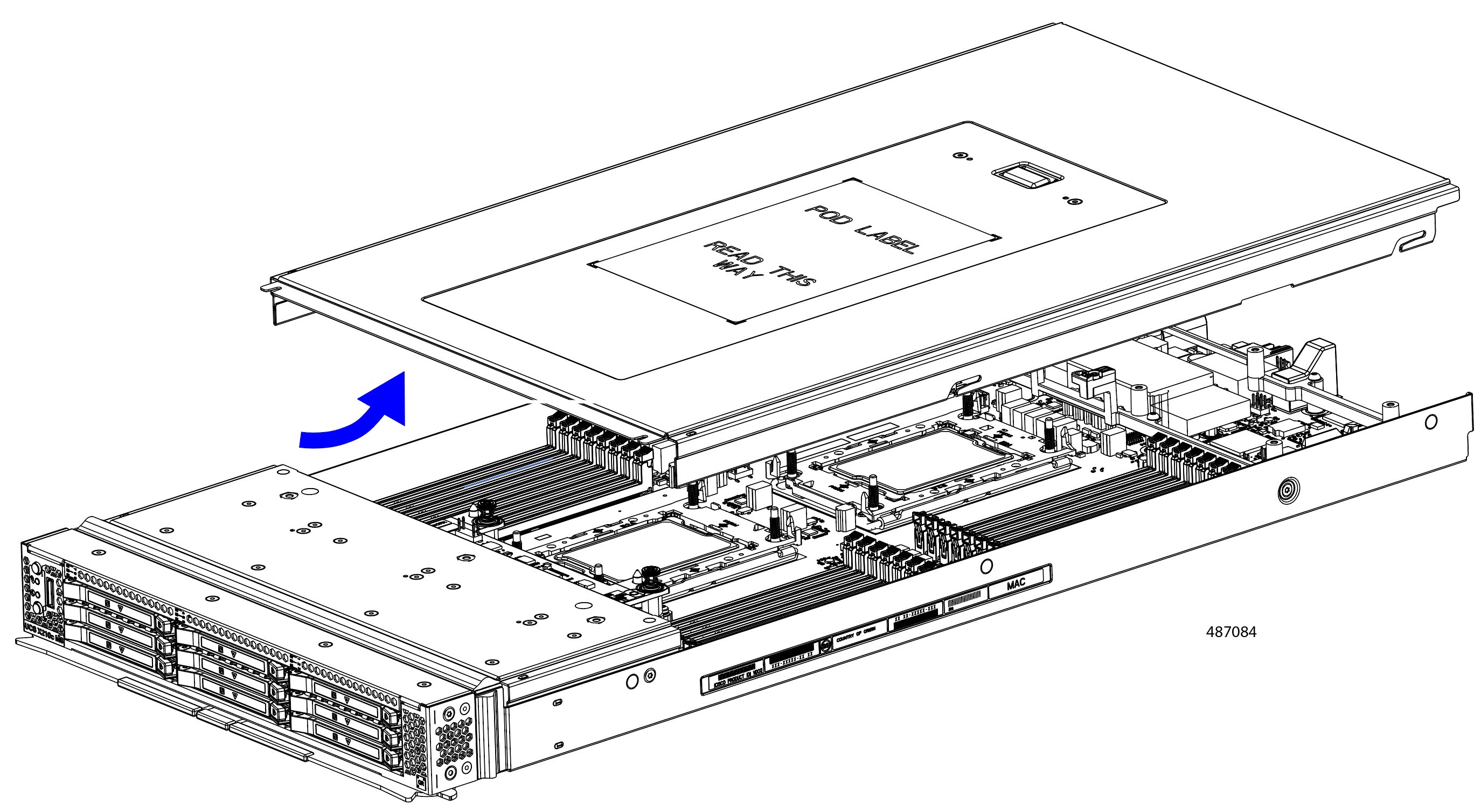
Removing a Compute Node Cover
To remove the cover of the compute node, follow these steps:
Procedure
|
Step 1 |
Press and hold the button down as shown in the figure below.
|
|
Step 2 |
While holding the back end of the cover, slide it back, then pull it up to lift the top cover off of the compute node. By sliding the cover back, you enable the front edge to clear the metal lip on the rear of the front mezzanine module. |
Installing a Compute Node Cover
Use this task to install a removed top cover on the compute node.
Procedure
|
Step 1 |
Notice the cutouts on the rear of the top cover. These cutouts receive the stopper pins on the compute node. 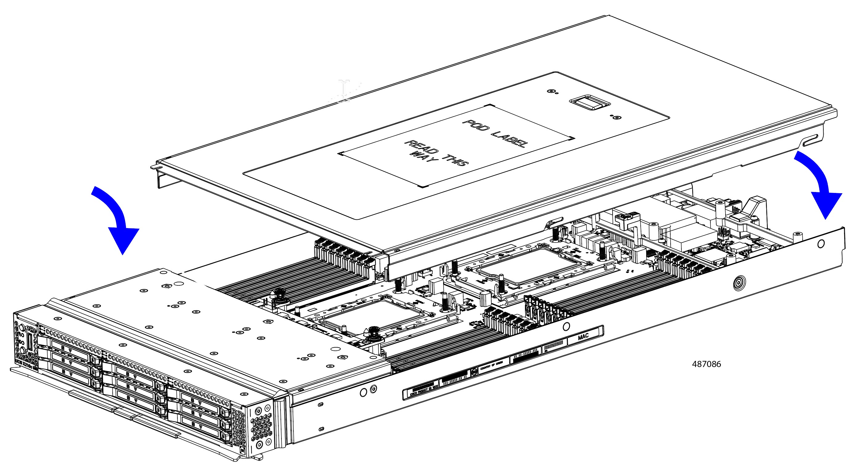 |
|
Step 2 |
Holding the top cover with the rear angled down, lower it onto the compute node. |
|
Step 3 |
Slide the compute node's cover until it hits the stopper pins. |
|
Step 4 |
Lower the front of the top cover onto the compute node. |
|
Step 5 |
Keeping the compute node's cover flat, slide it forward until the release button clicks. |
Removing the Front Mezzanine Module
To remove an existing front mezzanine module, you will remove screws on the side of the compute node's sheet metal tray and on the node's motherboard.
 Caution |
Do not operate the compute node without a front mezzanine module installed. |
Use the following procedure to remove an existing front mezzanine module.
Before you begin
The compute node must be removed from the chassis to perform this task.
Procedure
|
Step 1 |
Remove the top cover of the compute node. See Removing a Compute Node Cover. 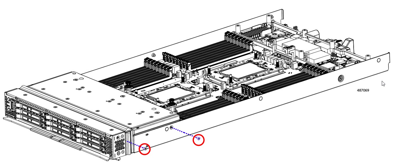 |
|
Step 2 |
Remove the screws.
|
|
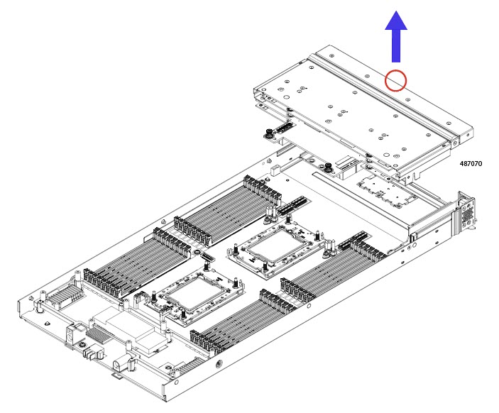
Step 3 |
Grasp the front mezzanine module at the middle of the top front edge and lift the front mezzanine module straight up to remove it from the compute node.
|
What to do next
Connect the front mezzanine E3.S Drive module to the compute node. See Installing the Front Mezzanine Module
Installing the Front Mezzanine Module
To install the front mezzanine module, you will insert screws on the side of the compute node's sheet metal tray and on the node's motherboard.
Use the following task to install the front mezzanine module.
Procedure
|
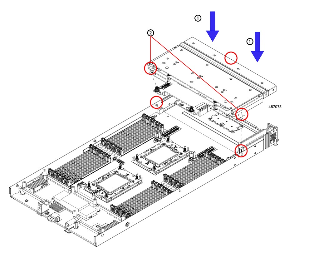
Step 1 |
Holding the front mezzanine module by the center of the top edge, keep the module level, and lower it down onto the compute node (1). |
||
|
Step 2 |
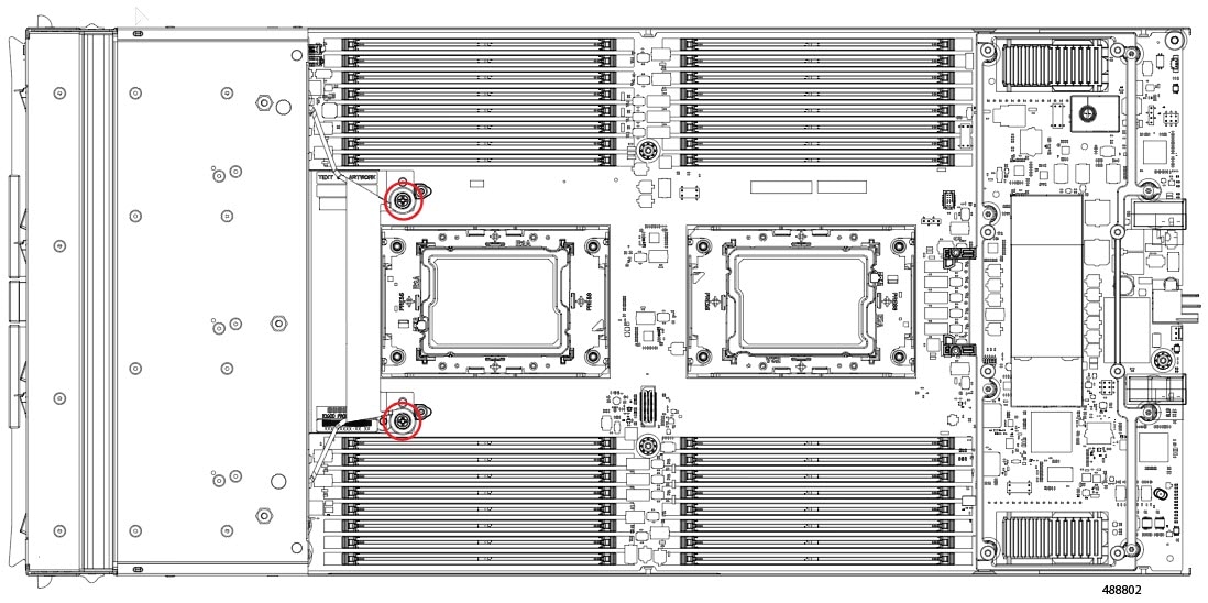
Align the rear captive screws with the threaded standoffs (2).
|
||
|
Step 3 |
Press down evenly on the module to seat the module's connectors into their sockets on the front mezzanine and compute node sidewall. |
||
|
Step 4 |
Using a Phillips screwdriver, and the torque driver, tighten the two rear captive screws to 5 in-lb of torque.
|
||
|
Step 5 |
Using a T8 Torx driver, tighten the four T8 flat head screws on the sides of the compute node (2 screws per side) to secure the module to the compute node.
|
||
|
Step 6 |
Replace the compute node top cover and reinstall the compute node into the chassis. |
 Feedback