Servicing the Front Mezzanine Module
The front mezzanine contains E3.S PCIe drives and field-replacable components.
To service these components, see the following topics:
Replacing a Drive
The UCSX-X10C-PTE3 Pass Through Controller supports 7 mm E3.S PCIe Gen 5 SSD drives. Each drive is front-loading into the front of the controller.
The maximum number of drives supported per Pass Through Controller, either nine or eight, depends on the X Series Compute Node that hosts the controller.
 Note |
In one case, slot 5 cannot accept an E3.S drive. For more information, see E3.S PCIe SSD Requirements and Restrictions. |
Use the following tasks to replace a E3.S drive.
E3.S PCIe SSD Requirements and Restrictions
For 7.5mm E3.S PCIe SSD drives, be aware of the following.
General Requirements and Restrictions
The following requirements and restrictions apply to any UCS X Series M8 Compute Node that hosts the UCSX-X10C-PTE3 front mezzanine module.
-
UEFI boot mode can be configured through the Boot Order Policy setting in the Server Policy supported by Cisco Intersight Managed Mode (IMM). For instructions about setting up UEFI boot mode through Cisco IMM, go to:
-
PCIe SSDs cannot be controlled with a SAS RAID controller because PCIe SSDs interface with the compute node via the PCIe bus.
-
UEFI boot is supported in all supported operating systems.
Requirements and Restrictions for the Cisco UCS X215c M8 Compute Node
The following requirements and restrictions apply to the UCS X215c M8 Compute Node, which is the AMD processor version, when it hosts the UCSX-X10C-PTE3 front mezzanine module.
-
With this combination of compute node and front mezz module, the maximum number of E3.S drives that can be installed is eight.
-
Slot 5 cannot support an E3.S drive due to electrical reasons. Slot five on the UCSX-X10C-PTE3 front mezzanine module must be covered with a drive filler panel (UCSC-E3S1T-F).
Hot Plug Considerations
Enabling Hot Plug Support
Surprise and OS-informed hot plug is supported with the following conditions:
-
VMD must be enabled to support hot plug. VMD must be enabled before installing an OS on the drive.
-
If VMD is not enabled, surprise hot plug is not supported, and you must do OS-informed hot plug instead.
-
VMD is required for both surprise hot plug and drive LED support.
Removing a Drive
Use this task to remove a E3.S PCIe drive from the front mezzanine drive module.
 Caution |
Do not operate the system with an empty drive bay. If you remove a drive, you must reinsert a drive or cover the empty drive bay with a drive blank. |
Procedure
|
Step 1 |
Push the ejector button to open the ejector arm, swing the ejector arm open and then pull the drive from its slot.
|
||
|
Step 2 |
Place the drive on an antistatic mat or antistatic foam if you are not immediately reinstalling it in another compute node. |
||
|
Step 3 |
Install a drive blanking panel to maintain proper airflow and keep dust out of the drive bay if it will remain empty. |
What to do next
Cover the empty drive bay. Choose the appropriate option:
Installing a Drive
Caution |
For hot installation of drives, after the original drive is removed, you must wait for 20 seconds before installing a drive. Failure to allow this 20-second wait period causes the management software to display incorrect drive inventory information. If incorrect drive information is displayed, remove the affected drive(s), wait for 20 seconds, then reinstall them. |
To install a E3.S PCIe drive, follow this procedure:
Before you begin
Note |
Depending on the compute node where the pass through controller is installed, slot 5 cannot accept an E3.S drive. For more information, see E3.S PCIe SSD Requirements and Restrictions. |
Procedure
|
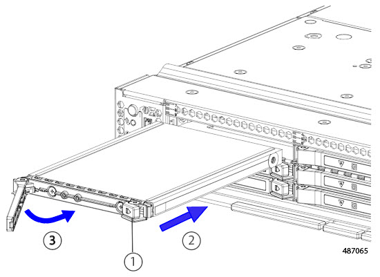
Step 1 |
Place the drive ejector arm into the open position by pushing the ejector button. |
|
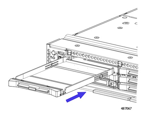
Step 2 |
Placing your fingers in the center of the drive, gently slide the drive into the empty drive bay until it seats into place. |
|
Step 3 |
Push the drive ejector arm into the closed position. You should feel the ejector arm click into place when it is in the closed position.
|
Removing a Drive Blank Filler
E3.S drives are contained in the front mezzanine storage module.
Note |
For the Cisco UCS X215c M8 Compute Node only, slot 5 must always have a filler panel because that slot does not support a drive. |
If your front mezzanine module has fewer than nine E3.S drives (UCSX-210c-M8) or eight E3.S drives (UCSX-215c-M8), you must install drive blank filler in the empty drive bays. All drive slots must contain a drive or drive blank filler.
Note |
Do not operate a front mezzanine E3.S module that has empty drive bays without a drive blank filler. |
Use this procedure to remove a drive blank filler.
Procedure
|
Grasp the front lip of the drive blank filler and pull the drive blank filler out of the slot. 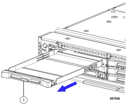
|
What to do next
Cover the empty drive bay. Choose the appropriate option:
Installing a Drive Blank Filler
Use this task to install a drive blank.
Procedure
|
Step 1 |
Align the drive blank filler so that the plastic bottom surface is facing down. |
|
Step 2 |
Holding the drive blank filler level, slide it into the empty slot.
|
 Feedback