|
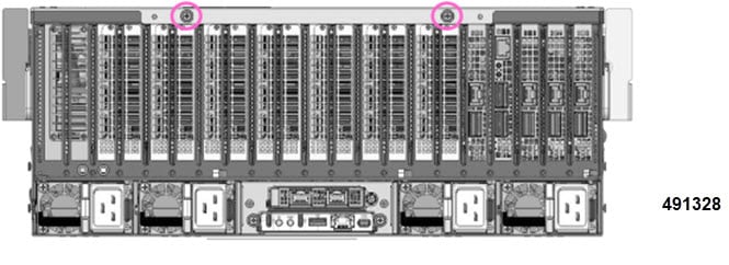
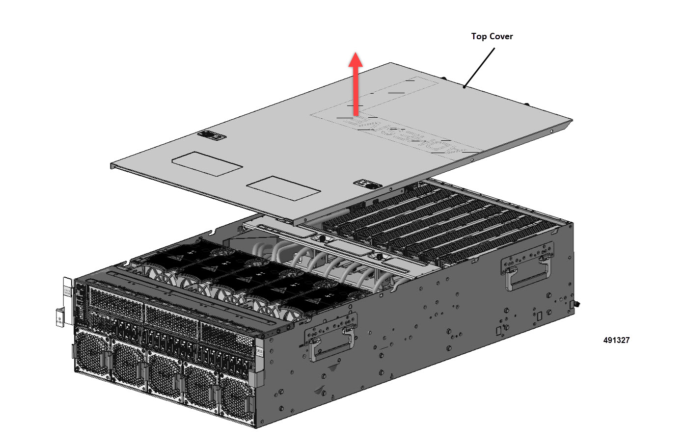
Step 1
|
Remove the top cover.
|
|
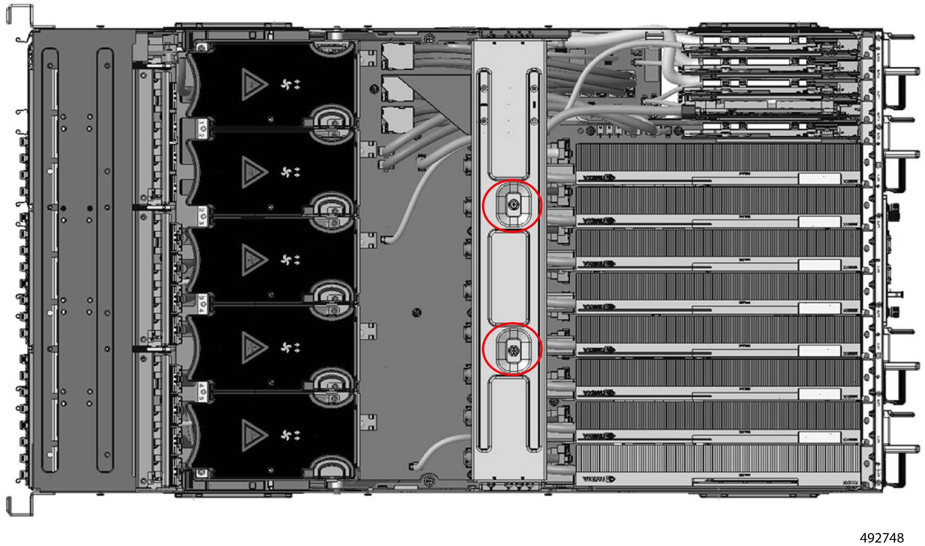
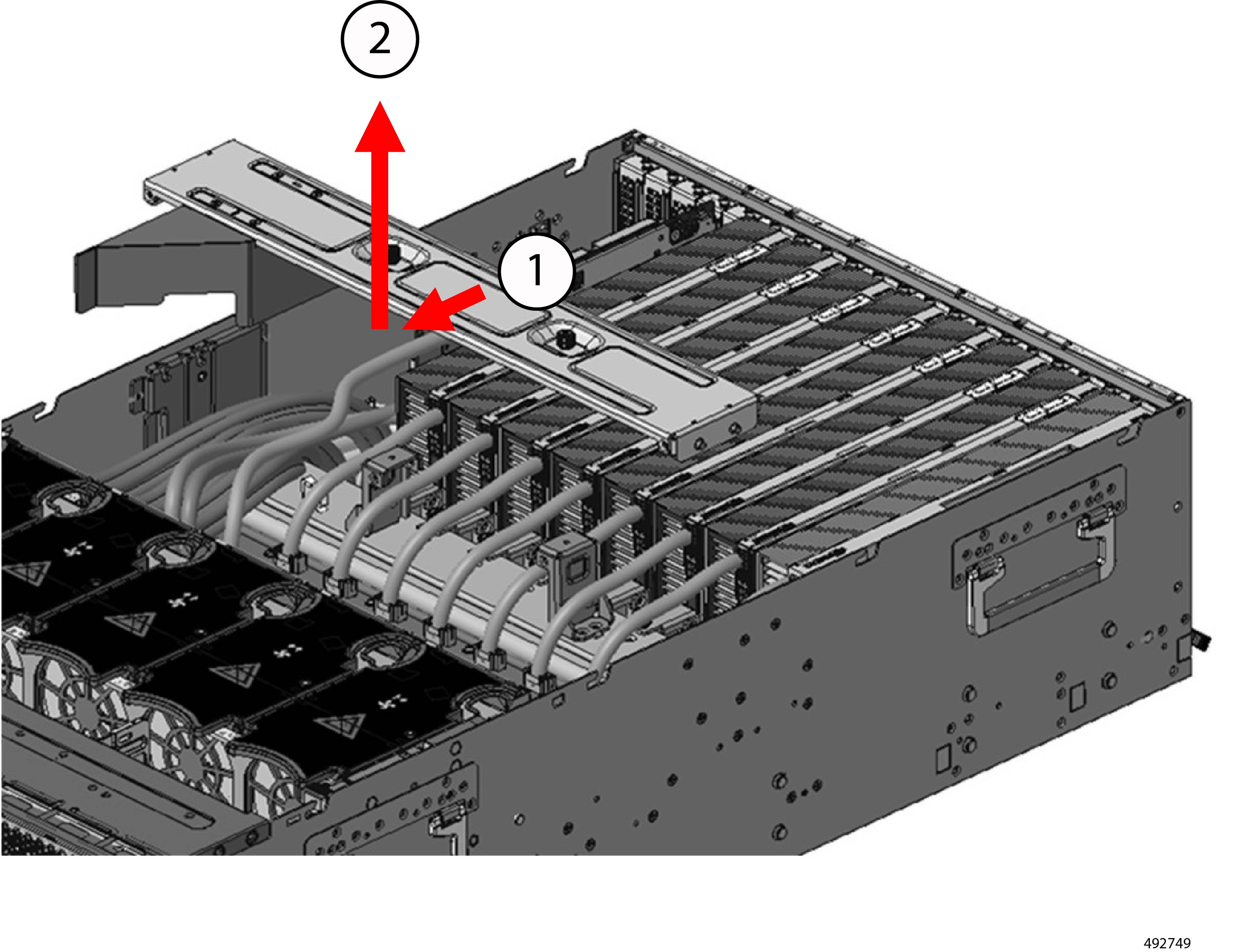
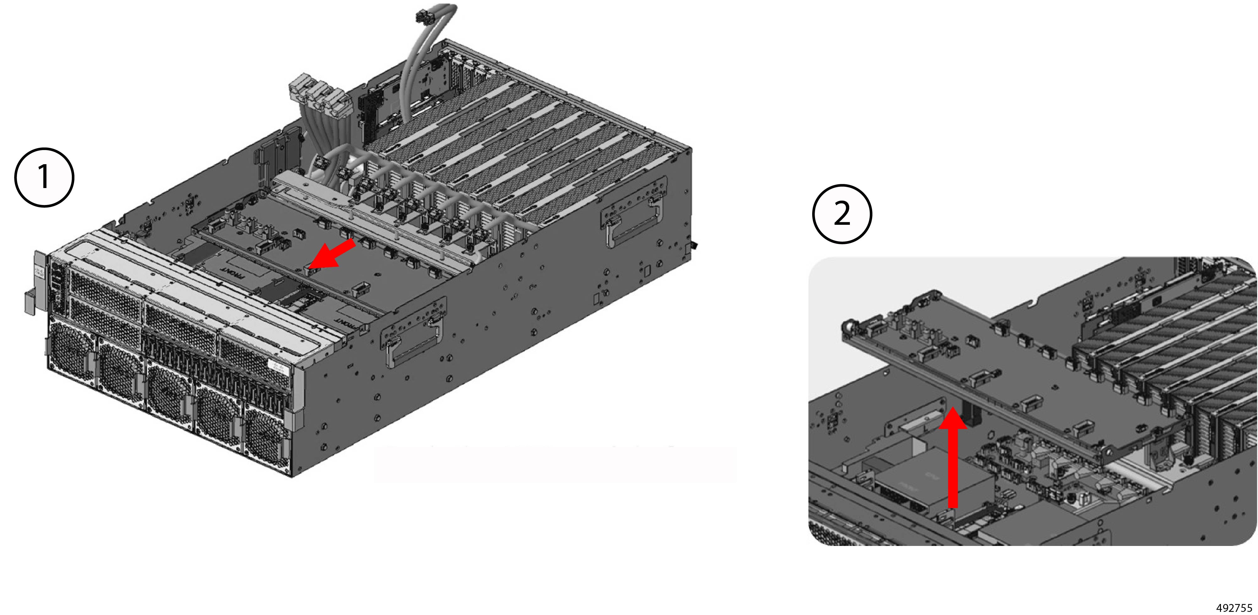
Step 2
|
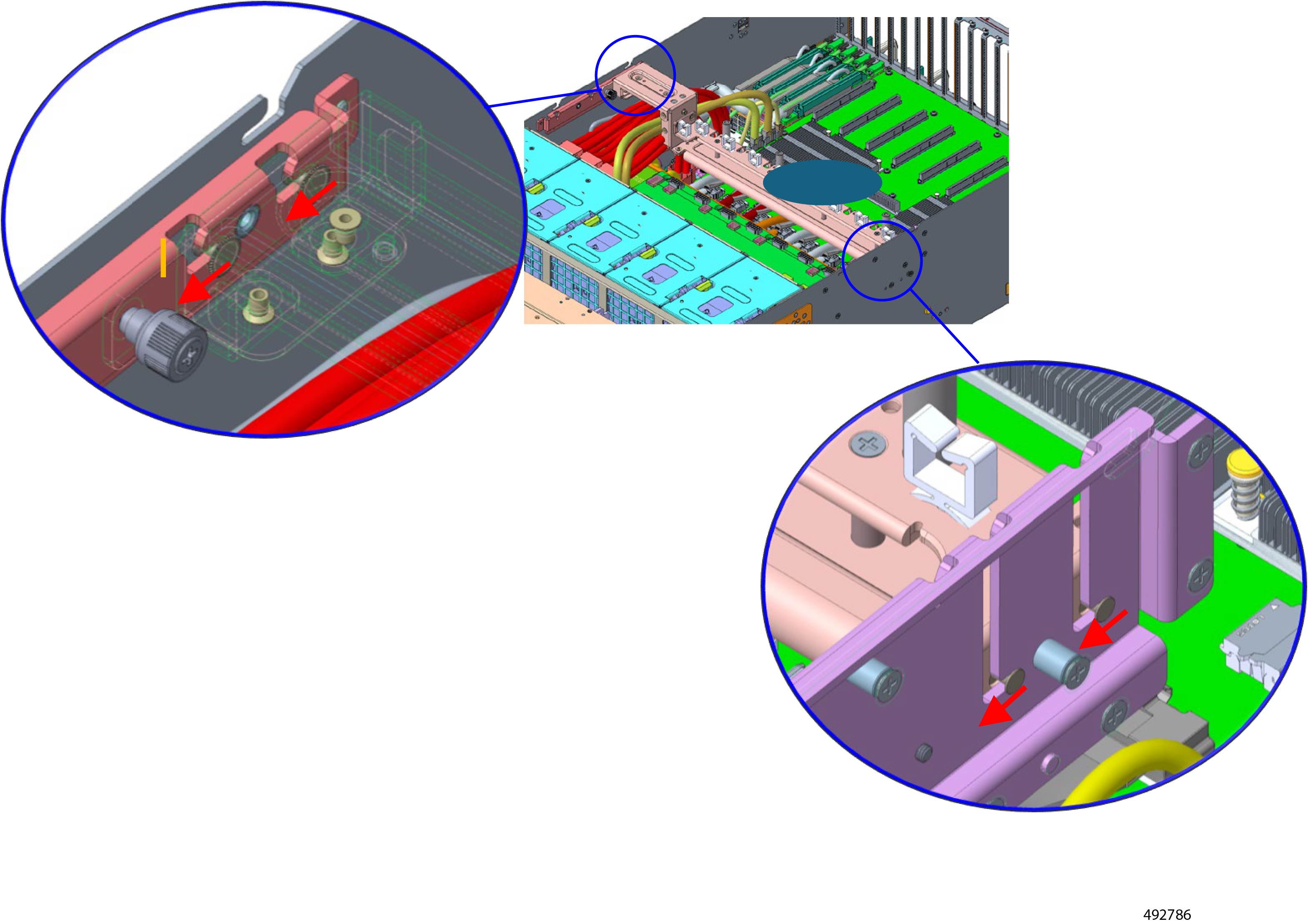
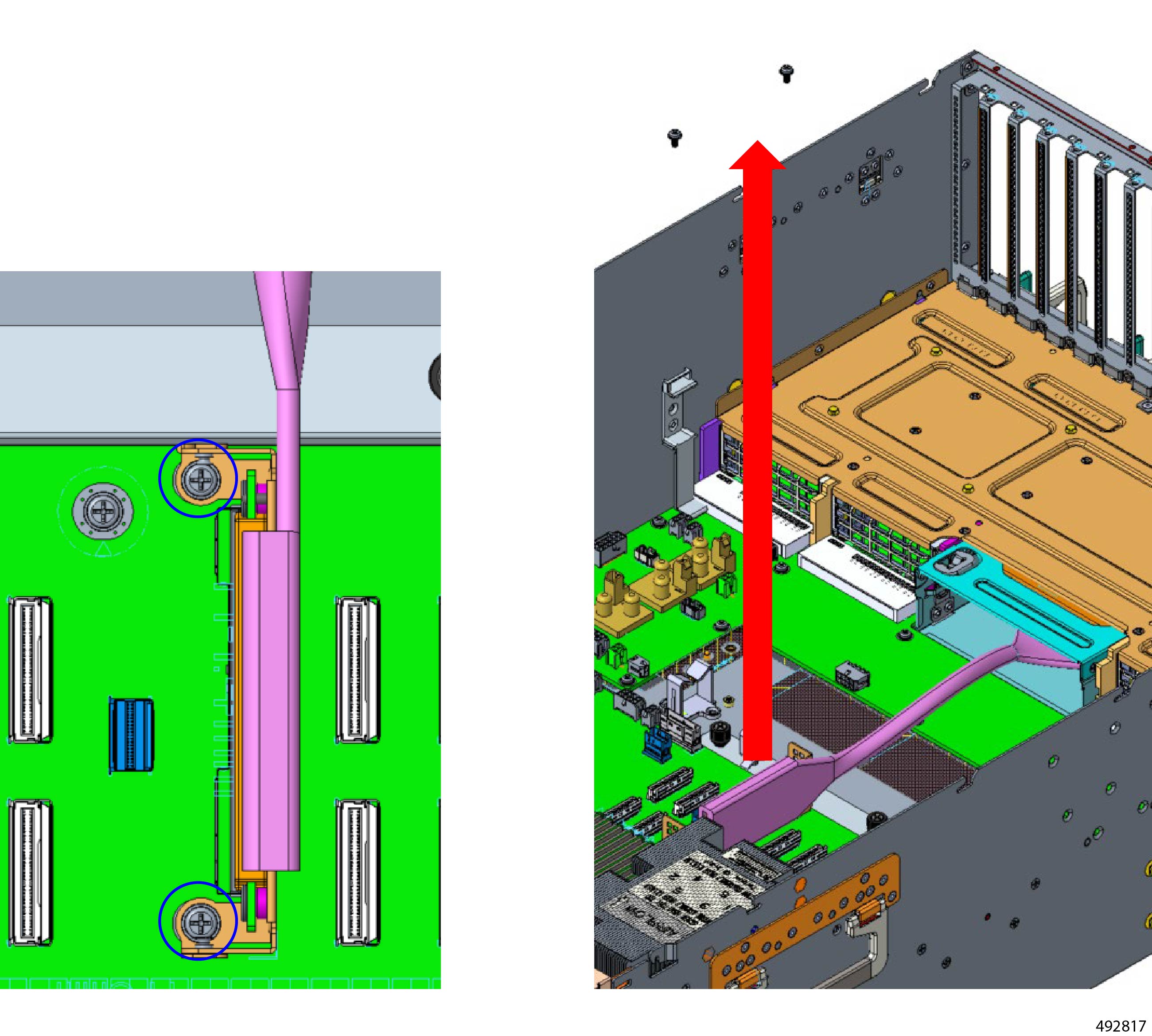
Remove the top support bracket.
-
Locate the two M3 thumbscrews, and use a #2 Phillips screwdriver to remove them.
-
Slide the support bracket forward then up to release it from the chassis.
|
|
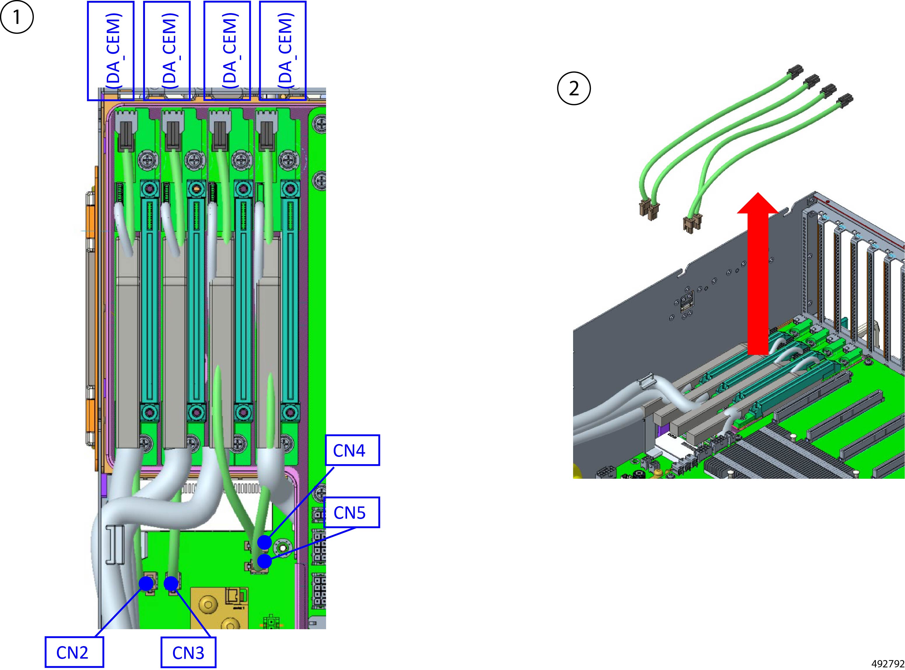
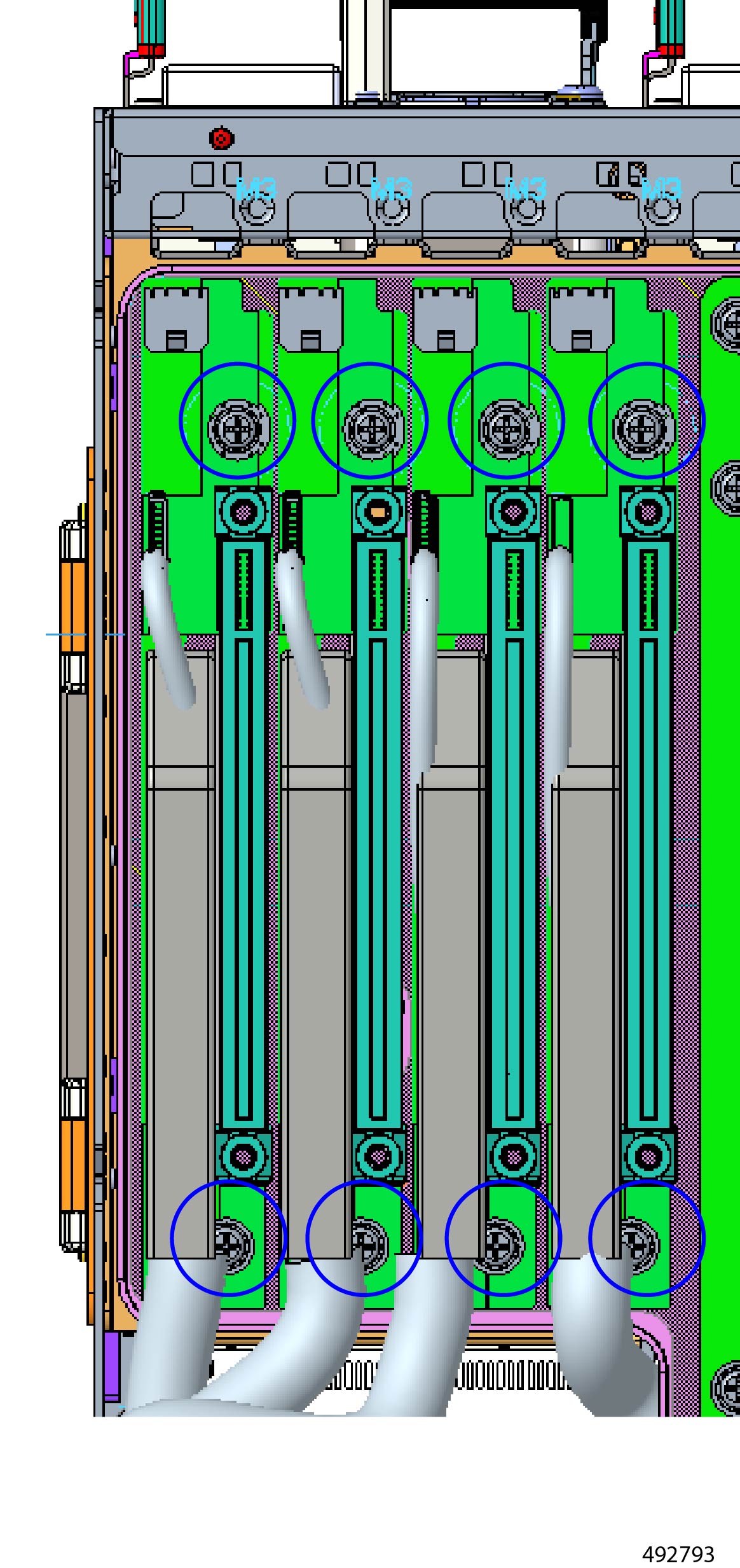
Step 3
|
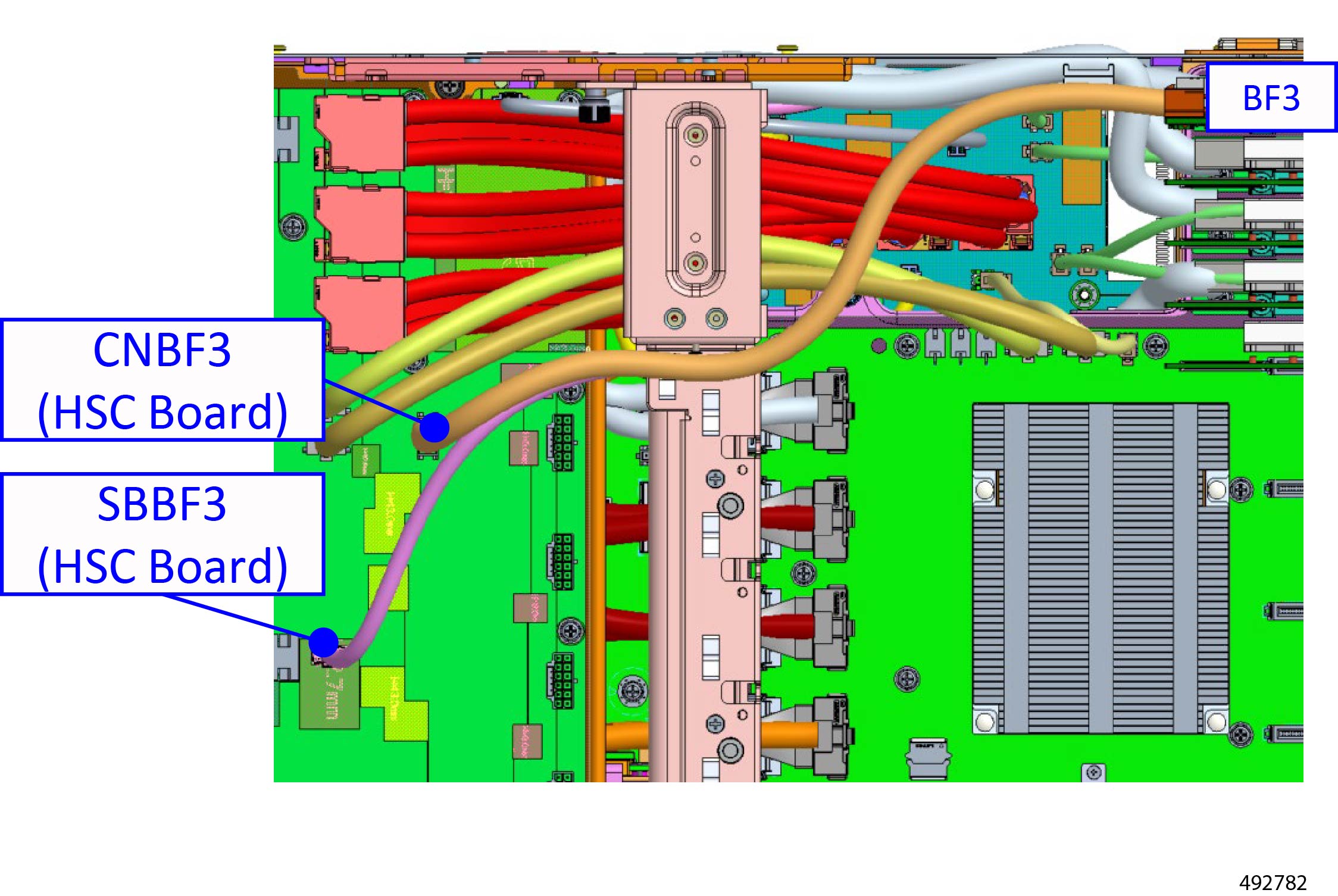
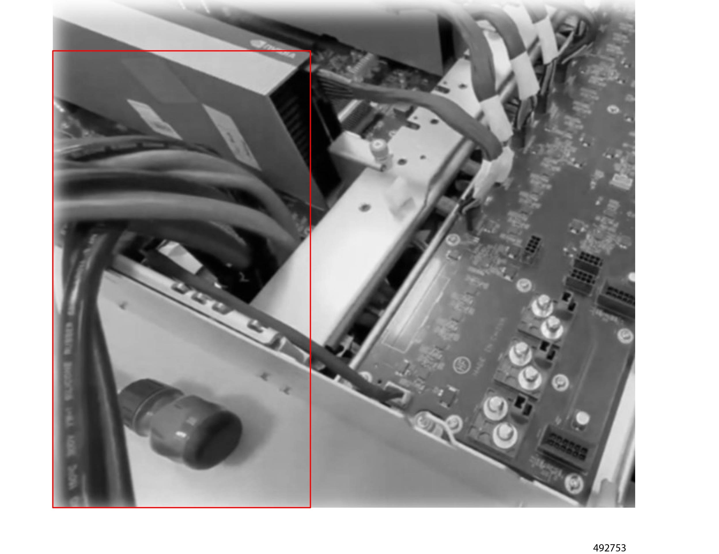
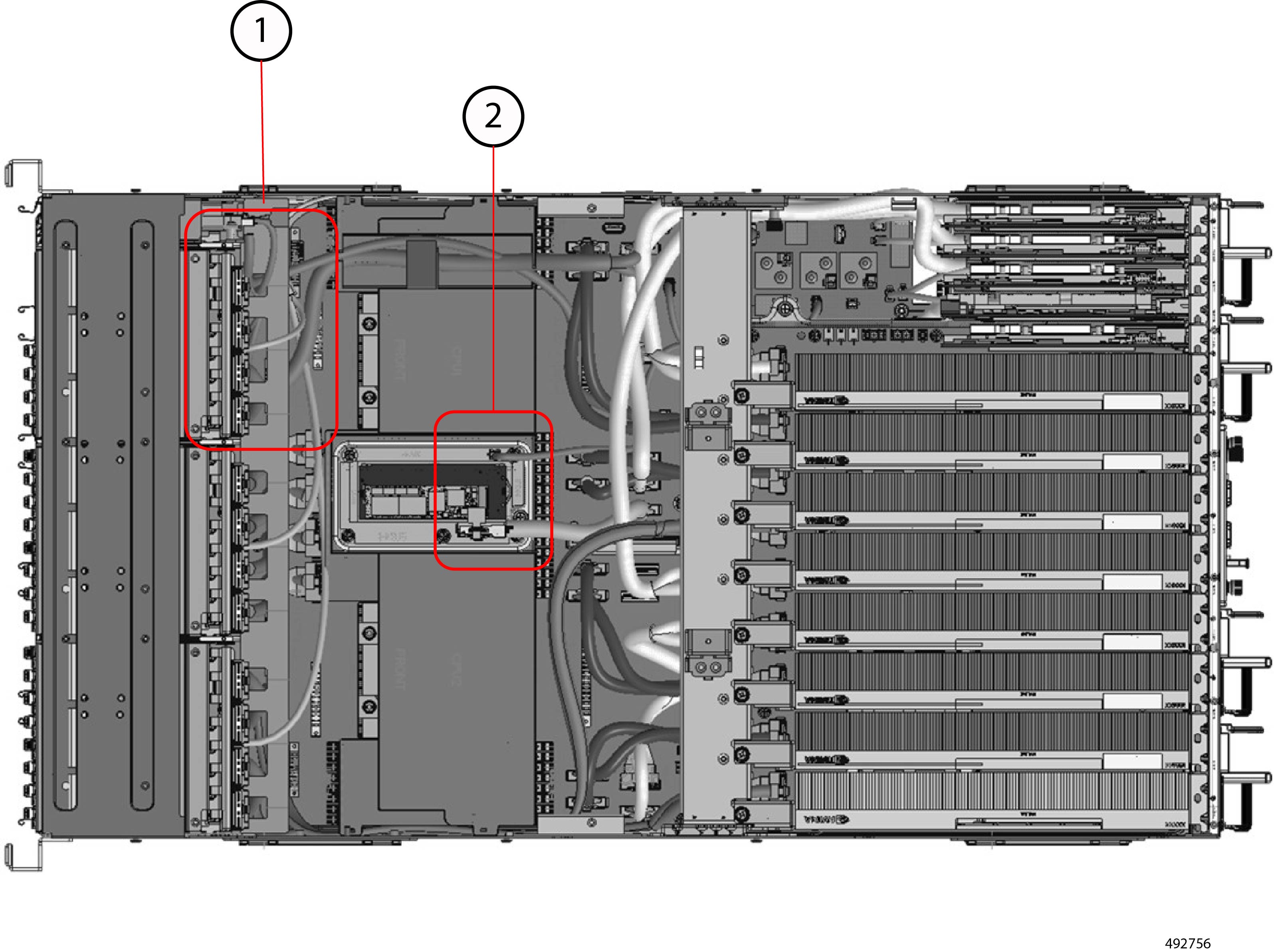
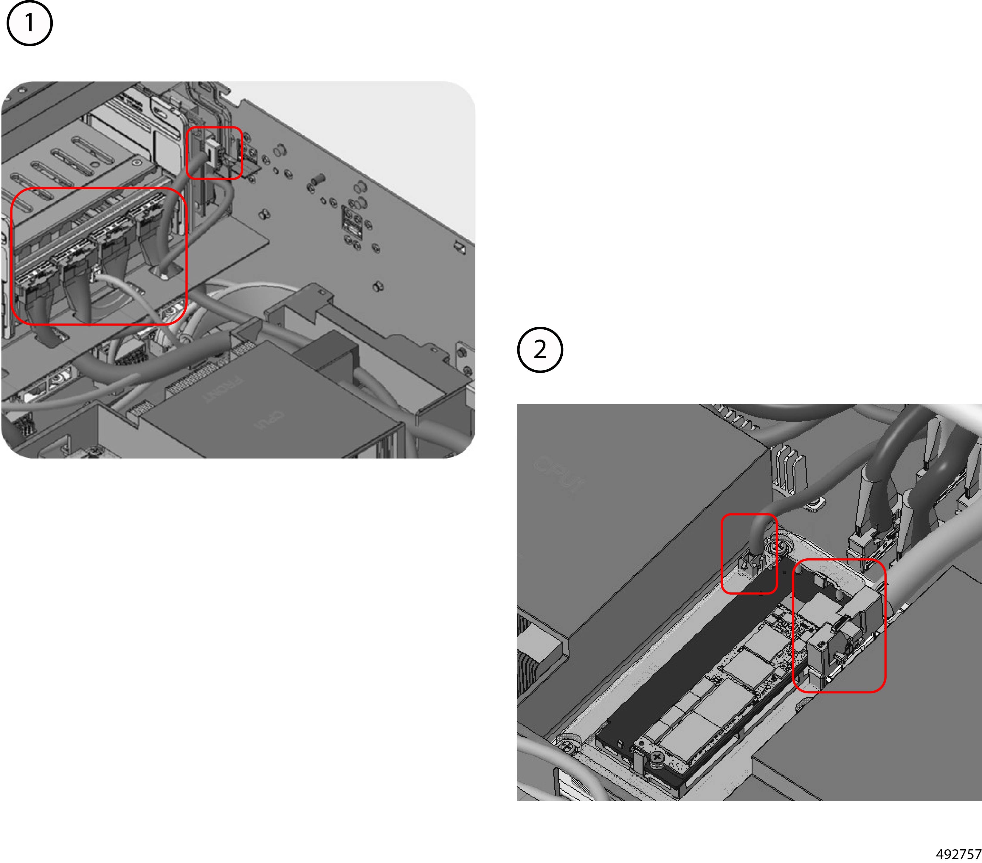
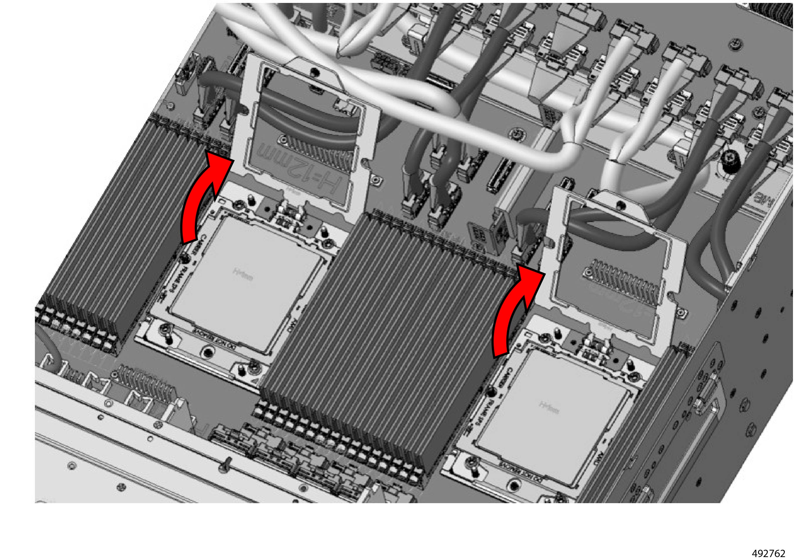
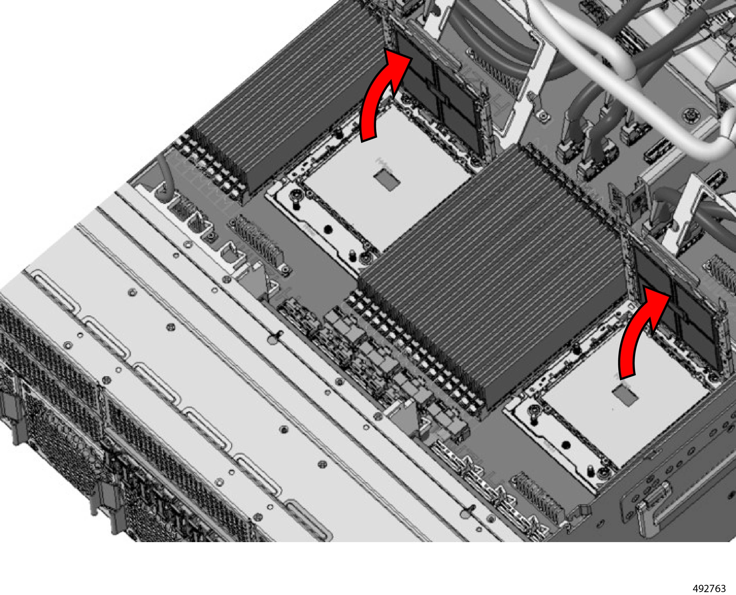
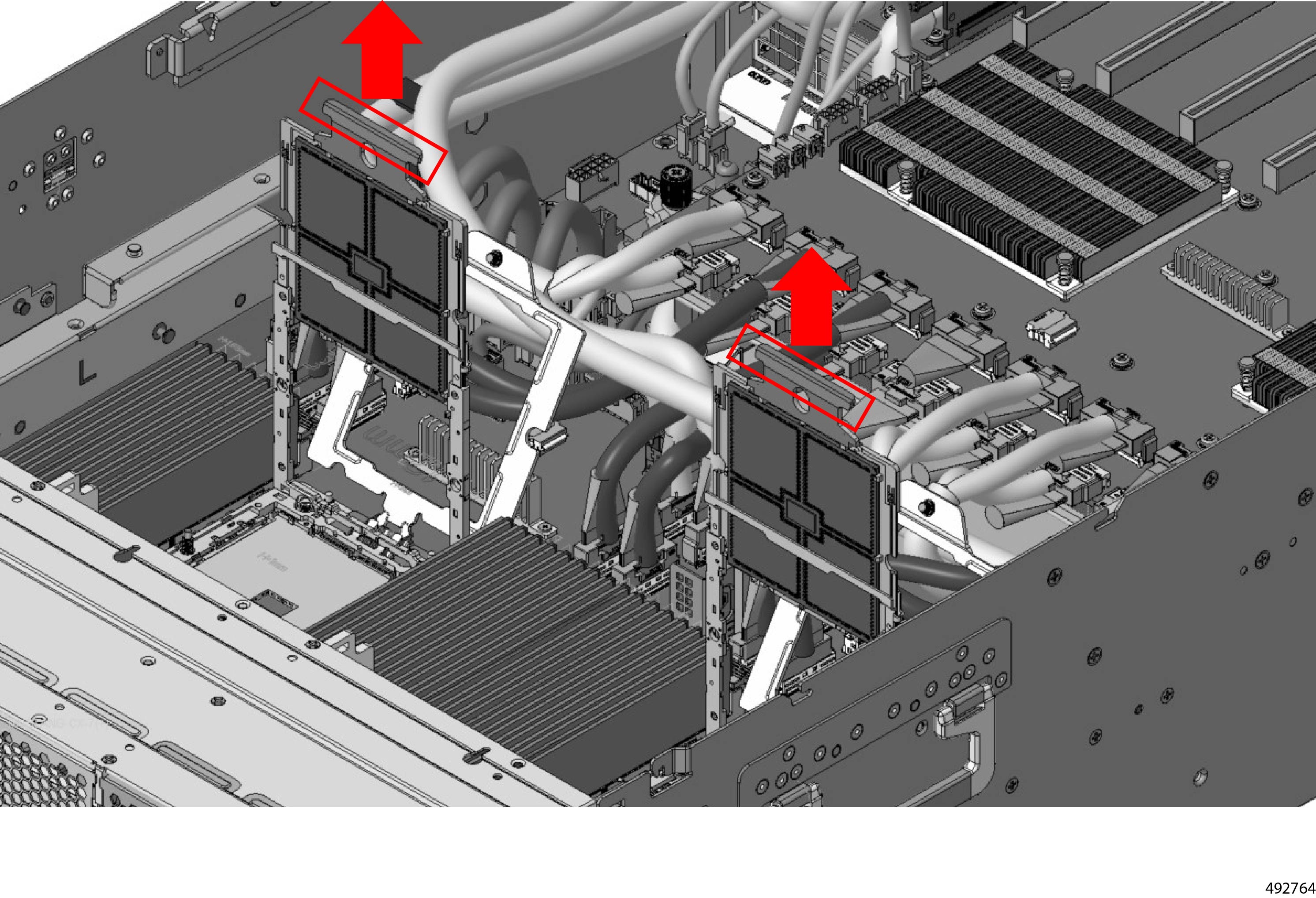
Remove the NVIDIA BlueField3 or ConnectX-7 GPU cables.
-
Locate the cables.
-
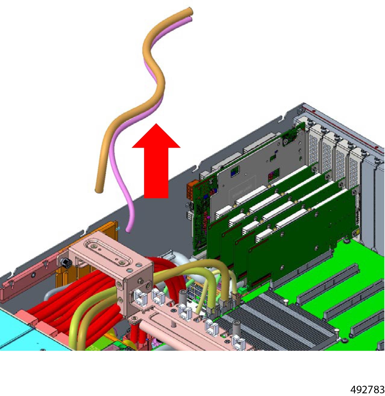
Remove the cables.
Although this illustration shows removing the cable completely, you can leave it attached to the cards, and just disconnect
it from the HSC board.
-
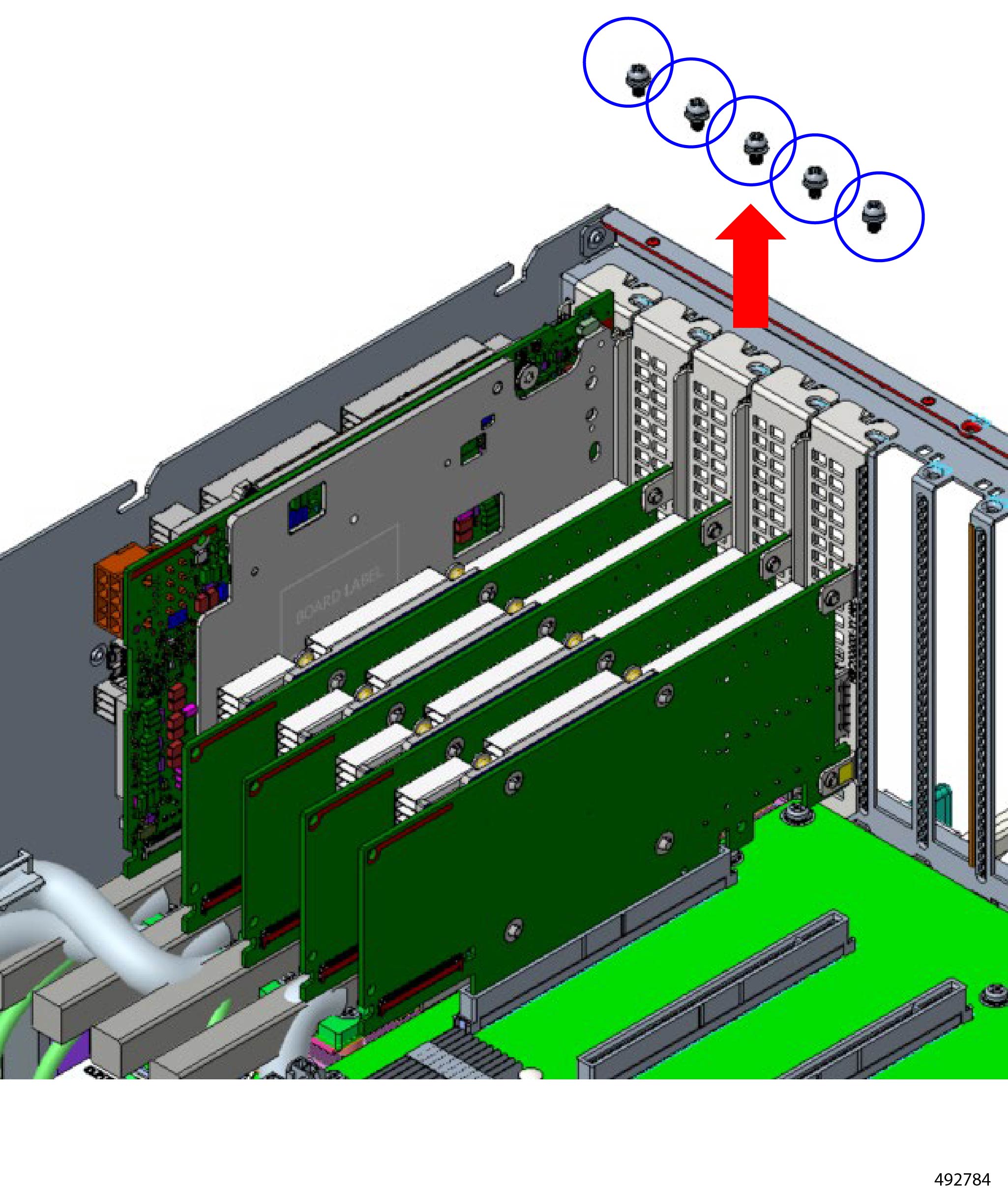
Remove the cards.
|
|
Step 4
|
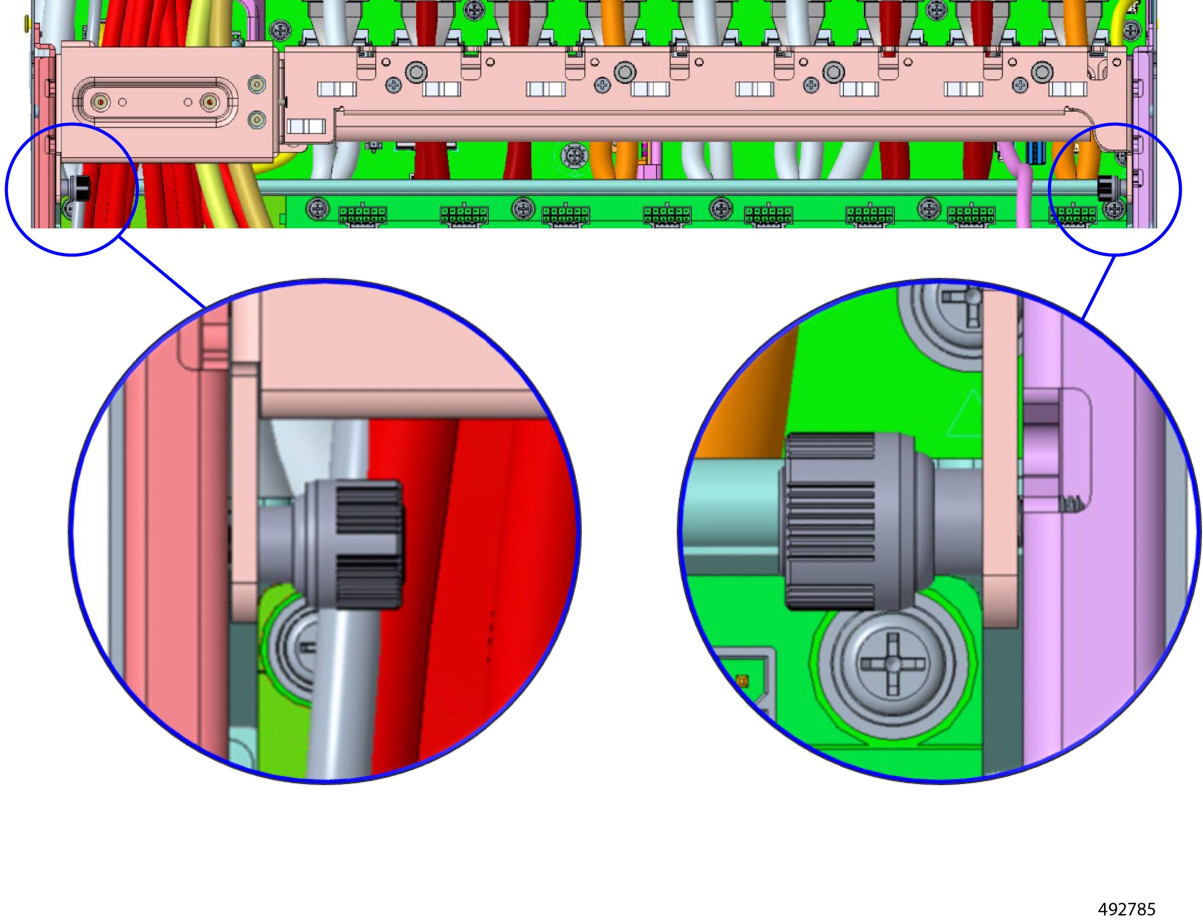
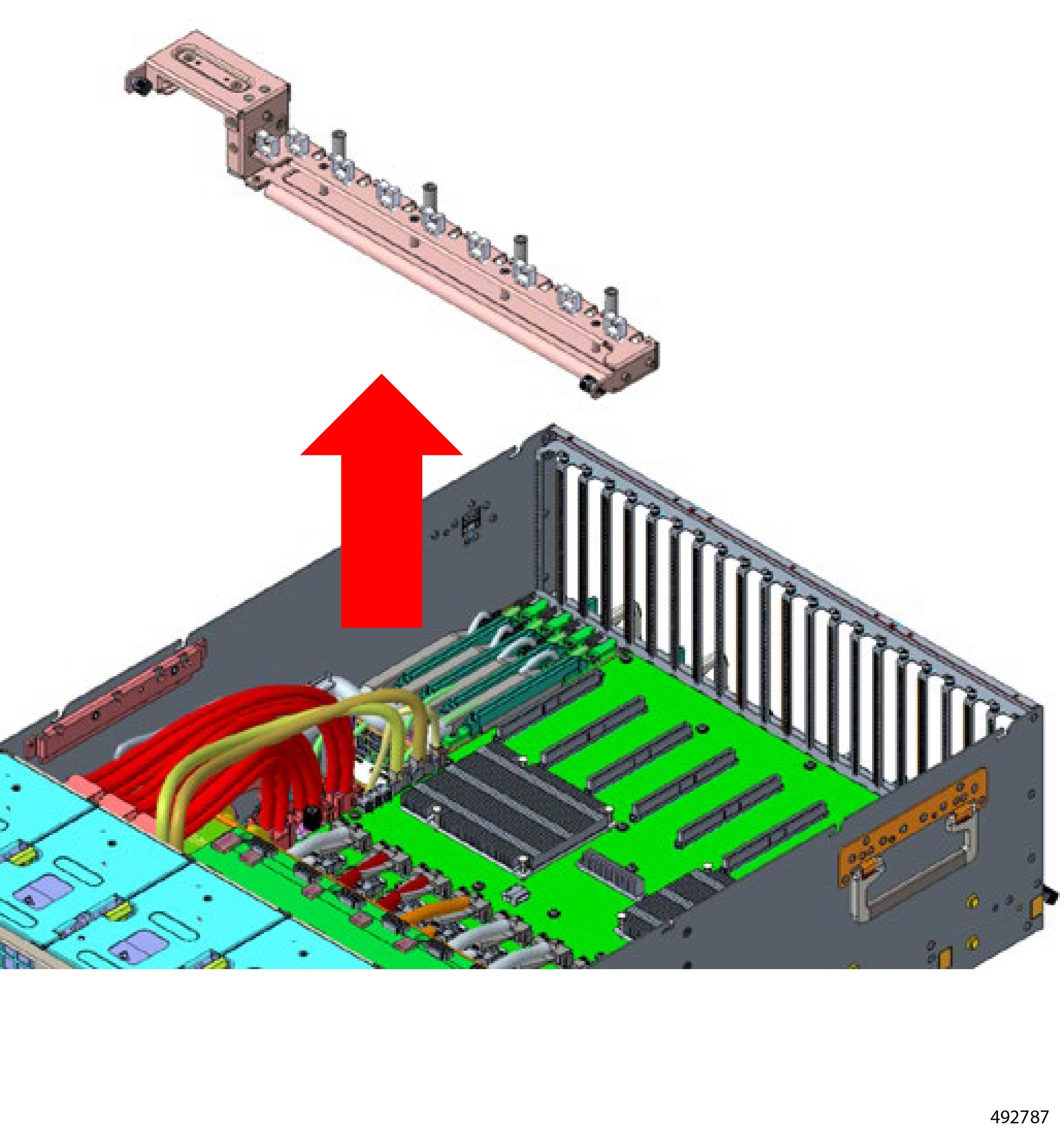
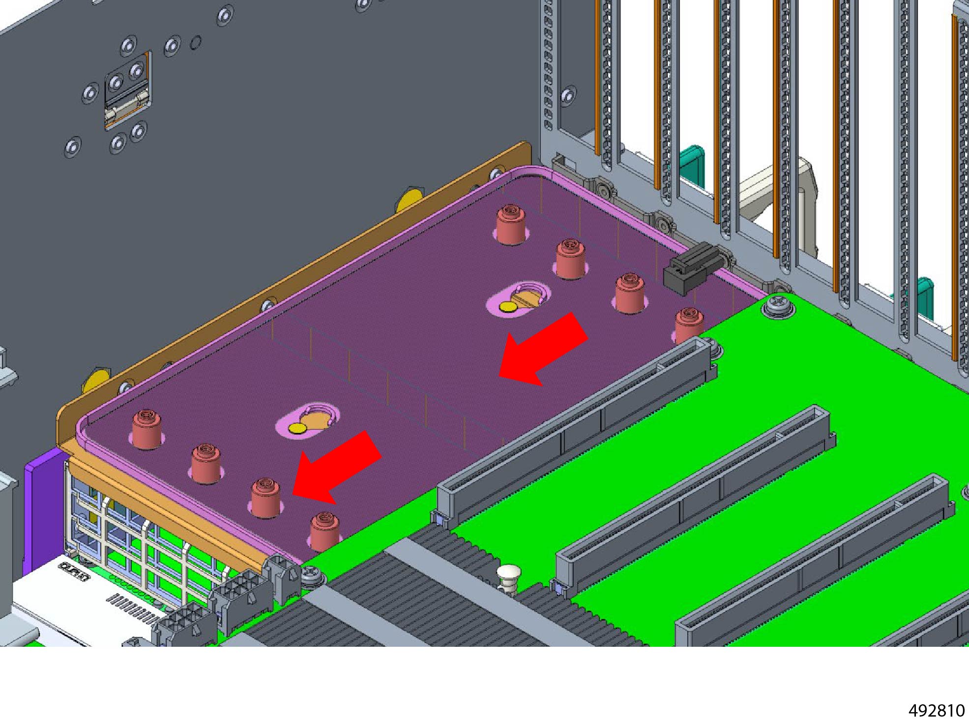
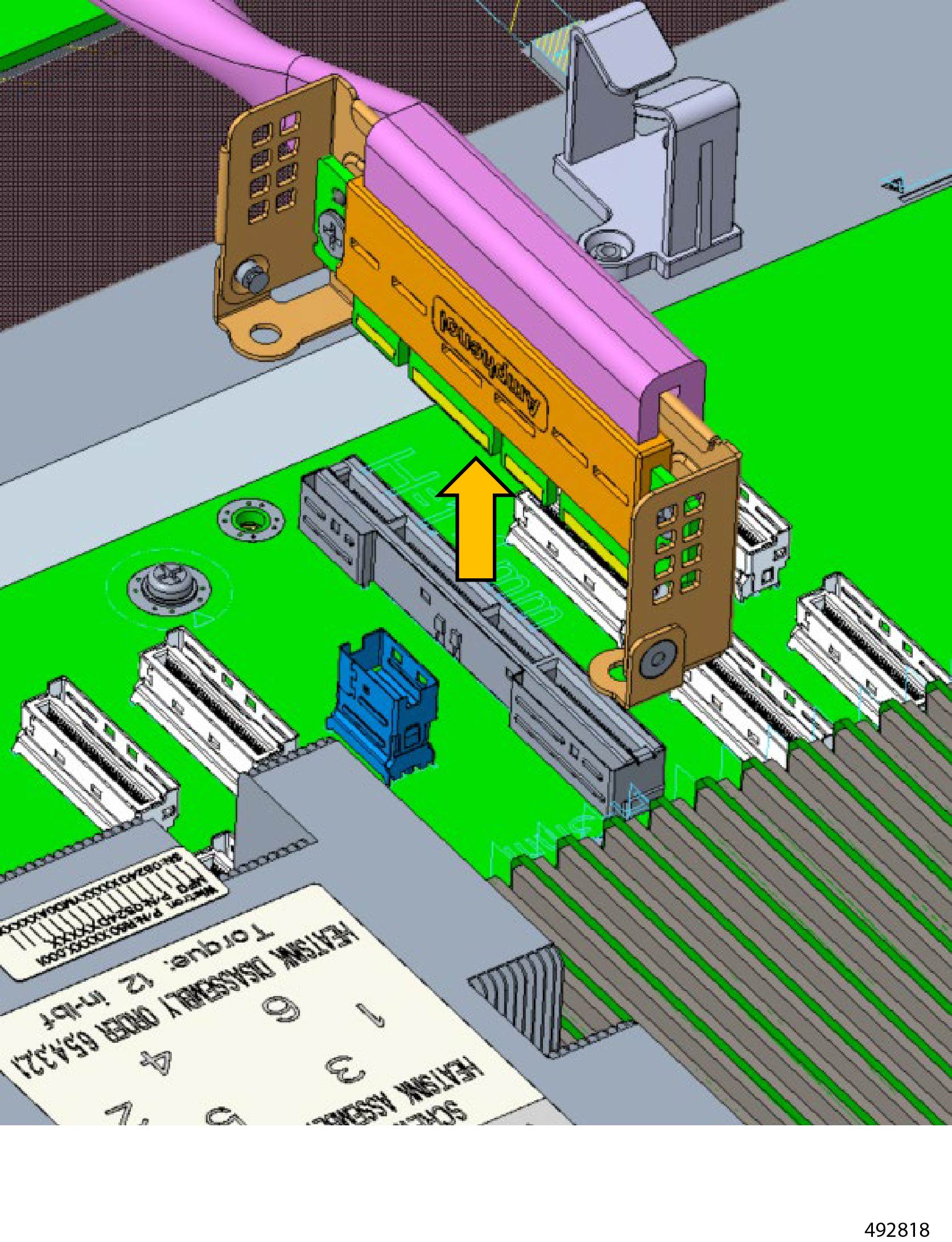
Remove the linking bar.
-
Remove the two thumbscrews.
-
Slide the linking bar to release it from the T pins.
-
Lift the linking bar out of the chassis.
|
|
Step 5
|
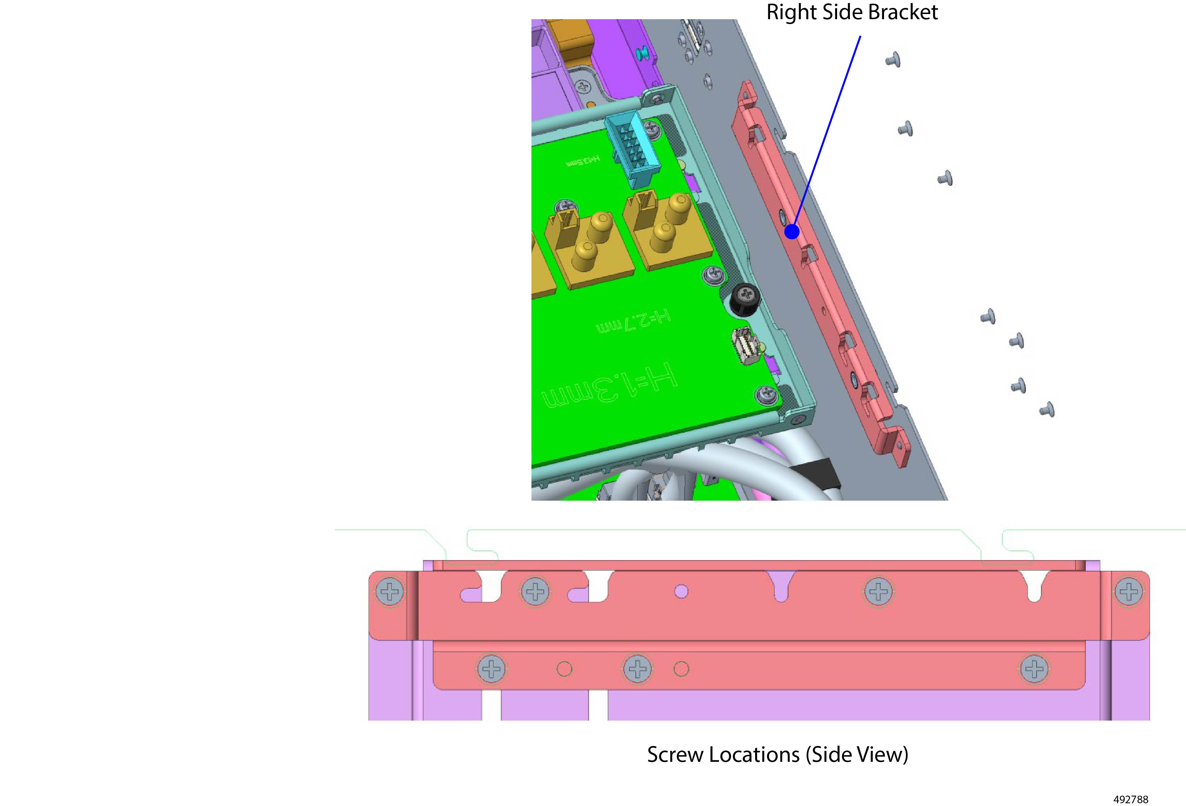
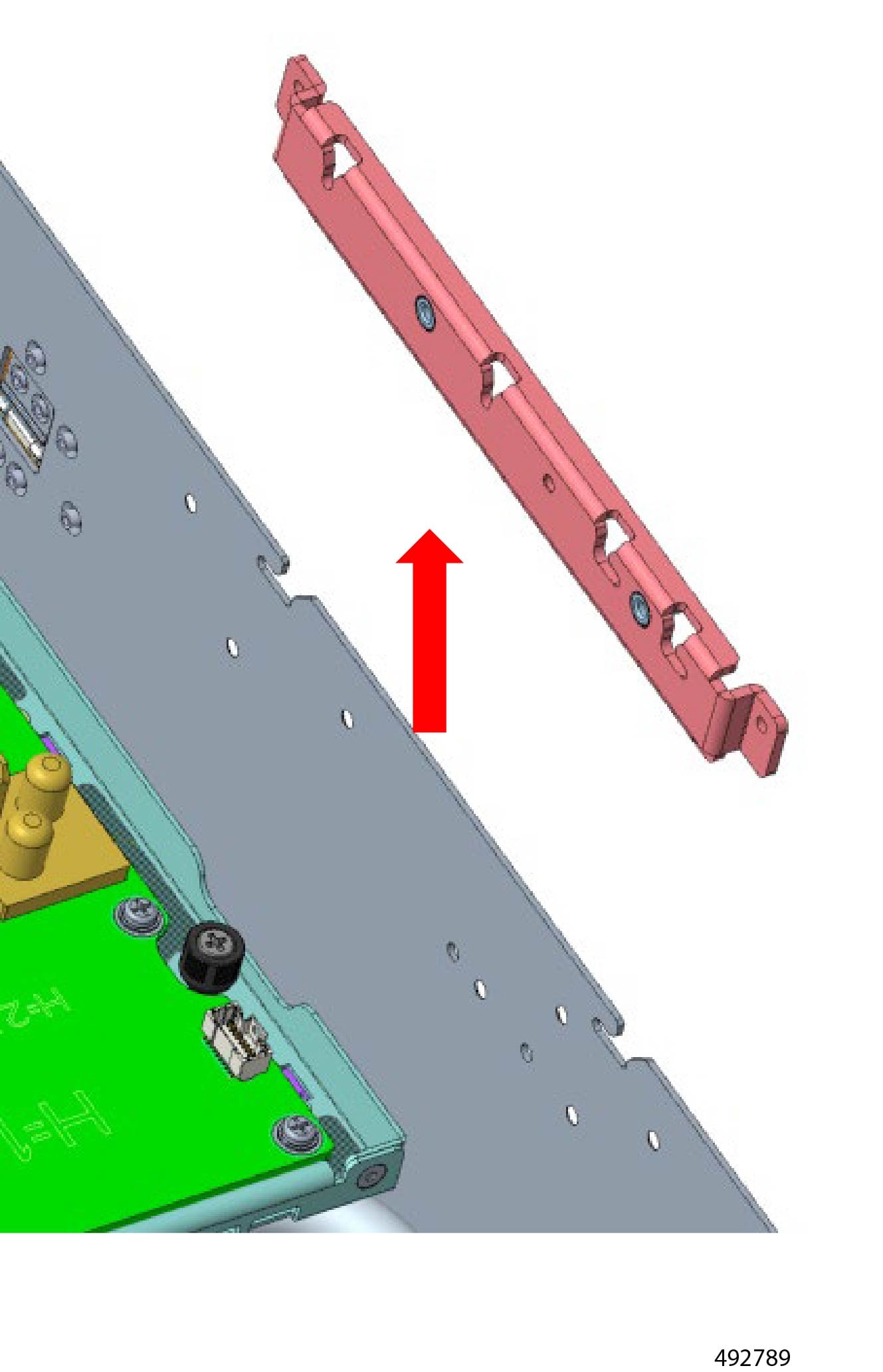
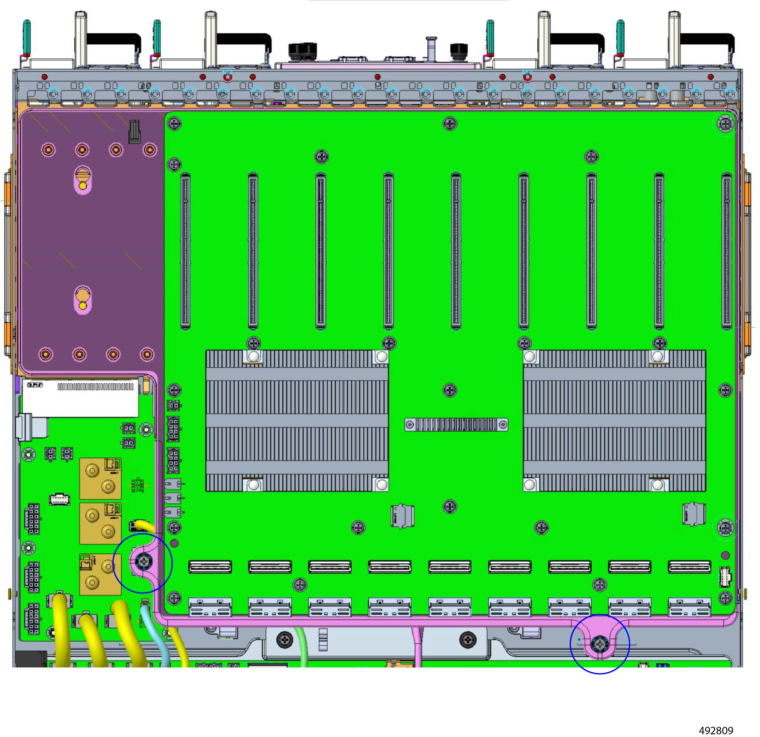
Remove the support bracket (right side).
-
Using the screwdriver, remove the screws.
-
Lift the bracket out of the chassis.
|
|
Step 6
|
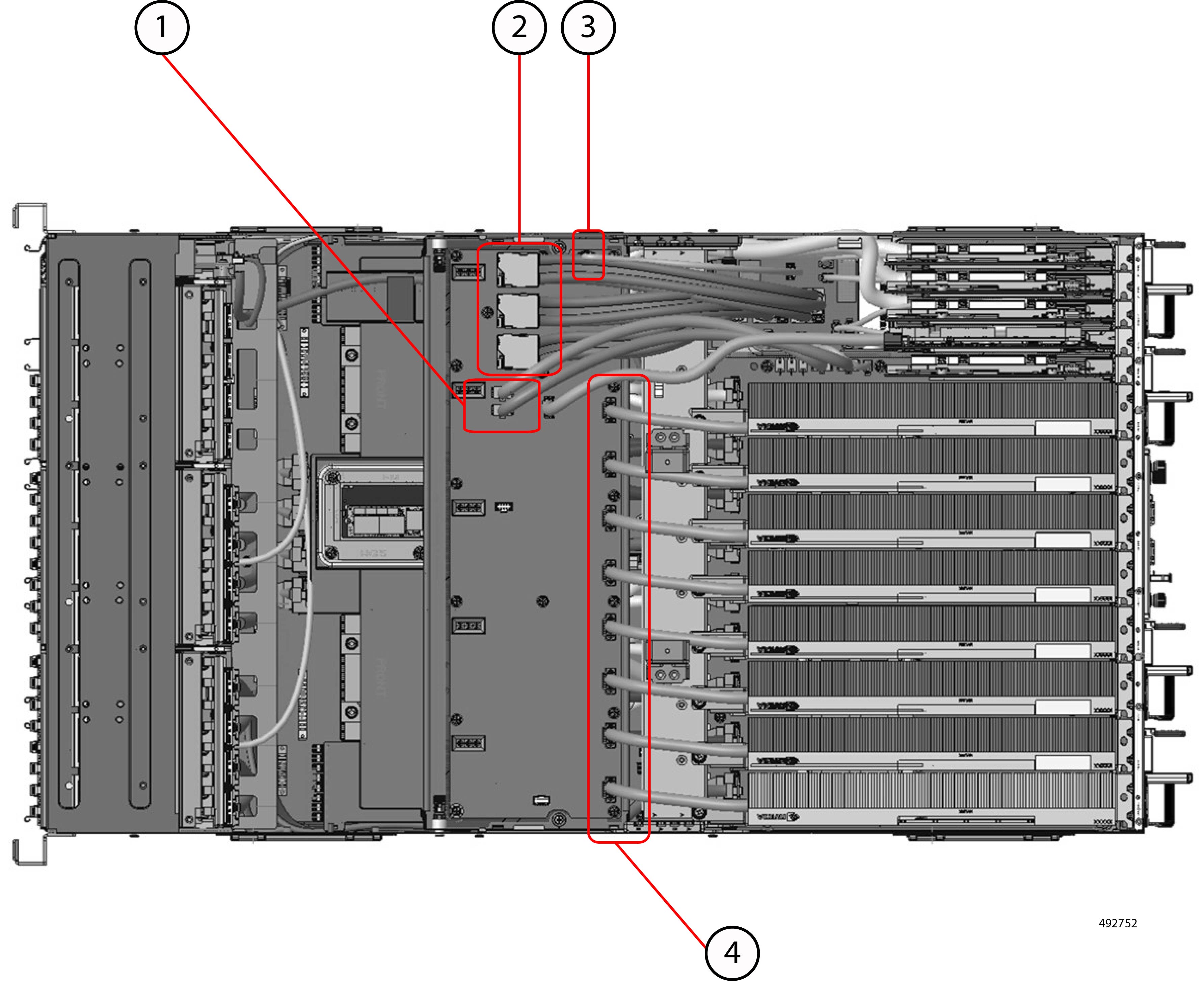
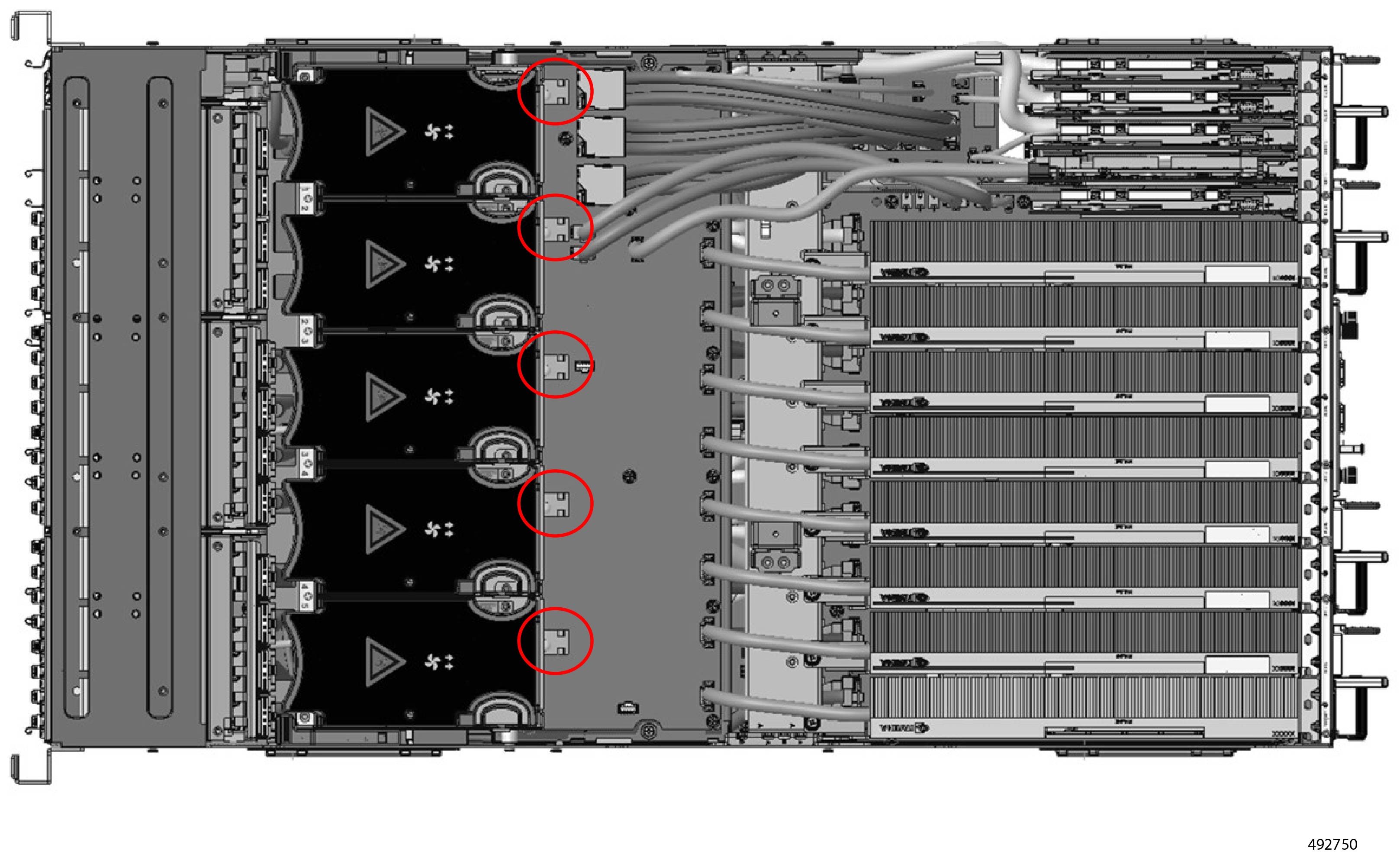
Remove the HSC Board Cables.
-
|
1
|
SW Board cables, two
|
|
2
|
PDB Board cables, three
|
|
3
|
BF3 NIC/ConnectX-7 cable, 1
|
|
4
|
GPU Power Cables
|
-
Clear the cables so they don't create an obstruction.
|
|
Step 7
|
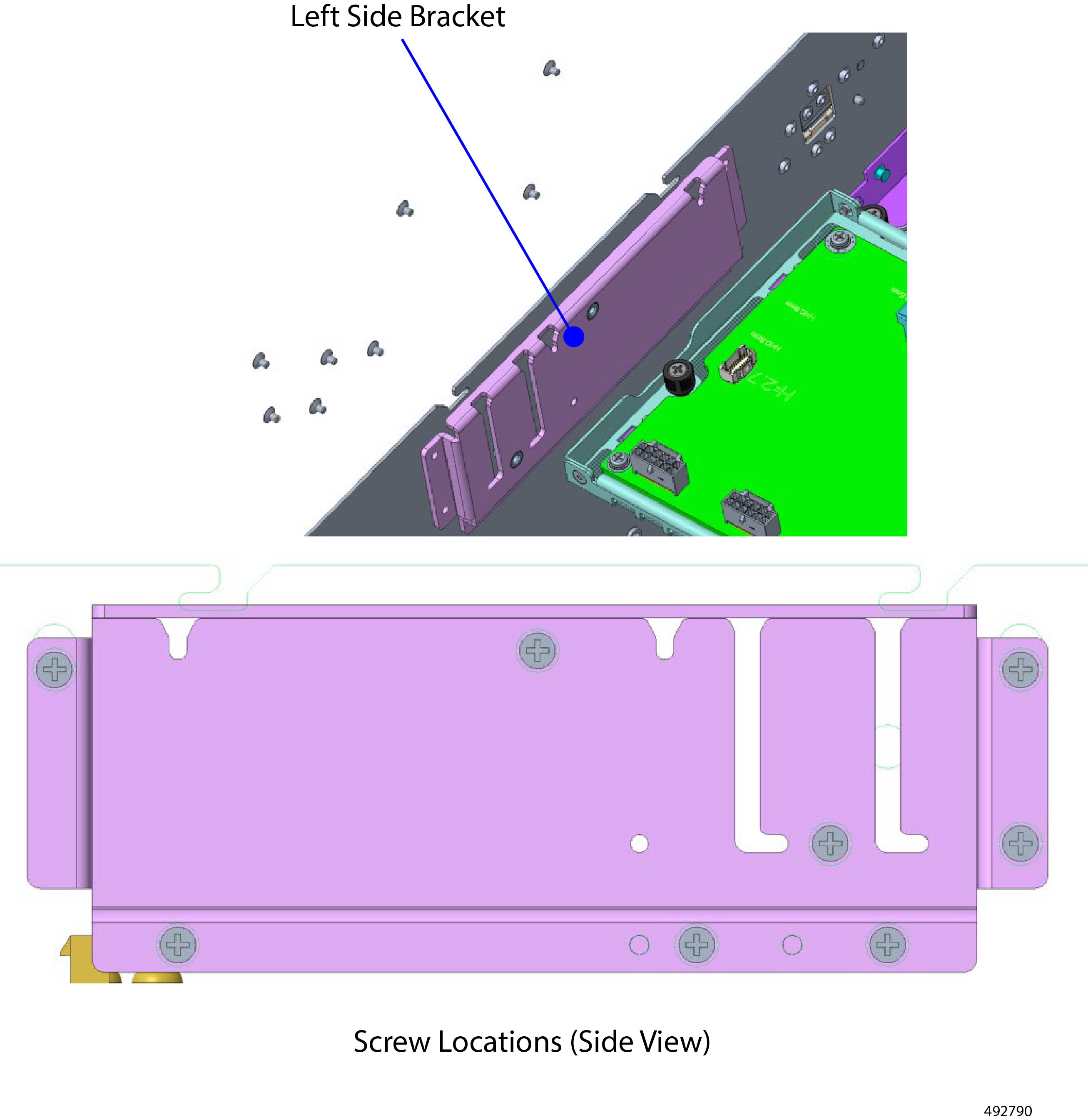
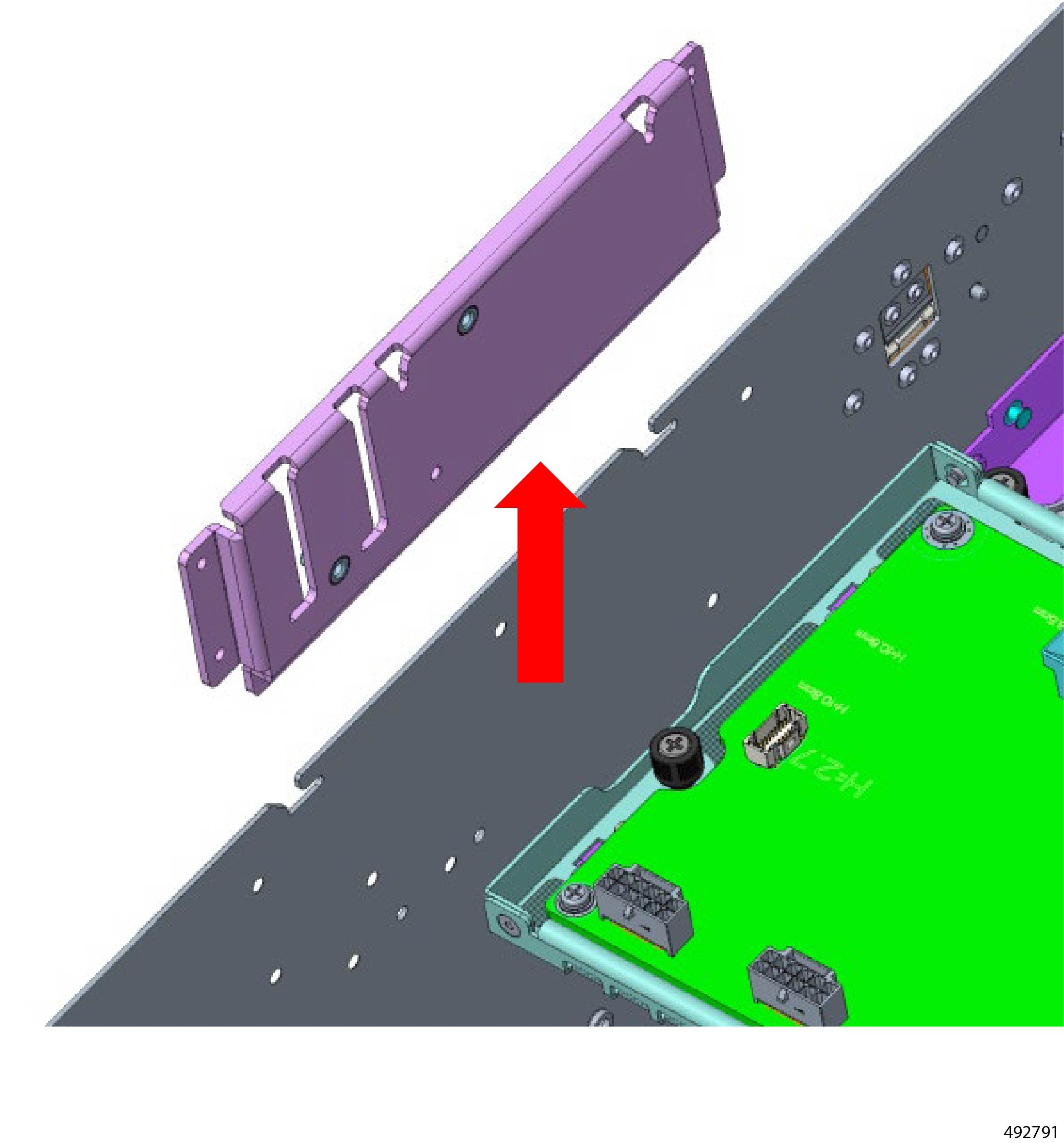
Remove the support bracket (left side).
-
Using the screwdriver, remove the screws.
-
Lift the bracket out of the chassis.
|
|
Step 8
|
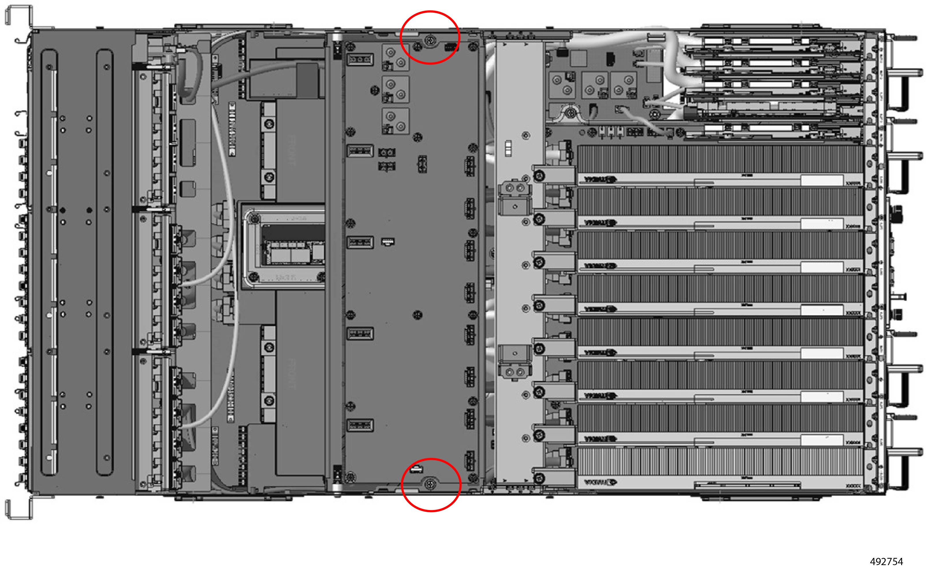
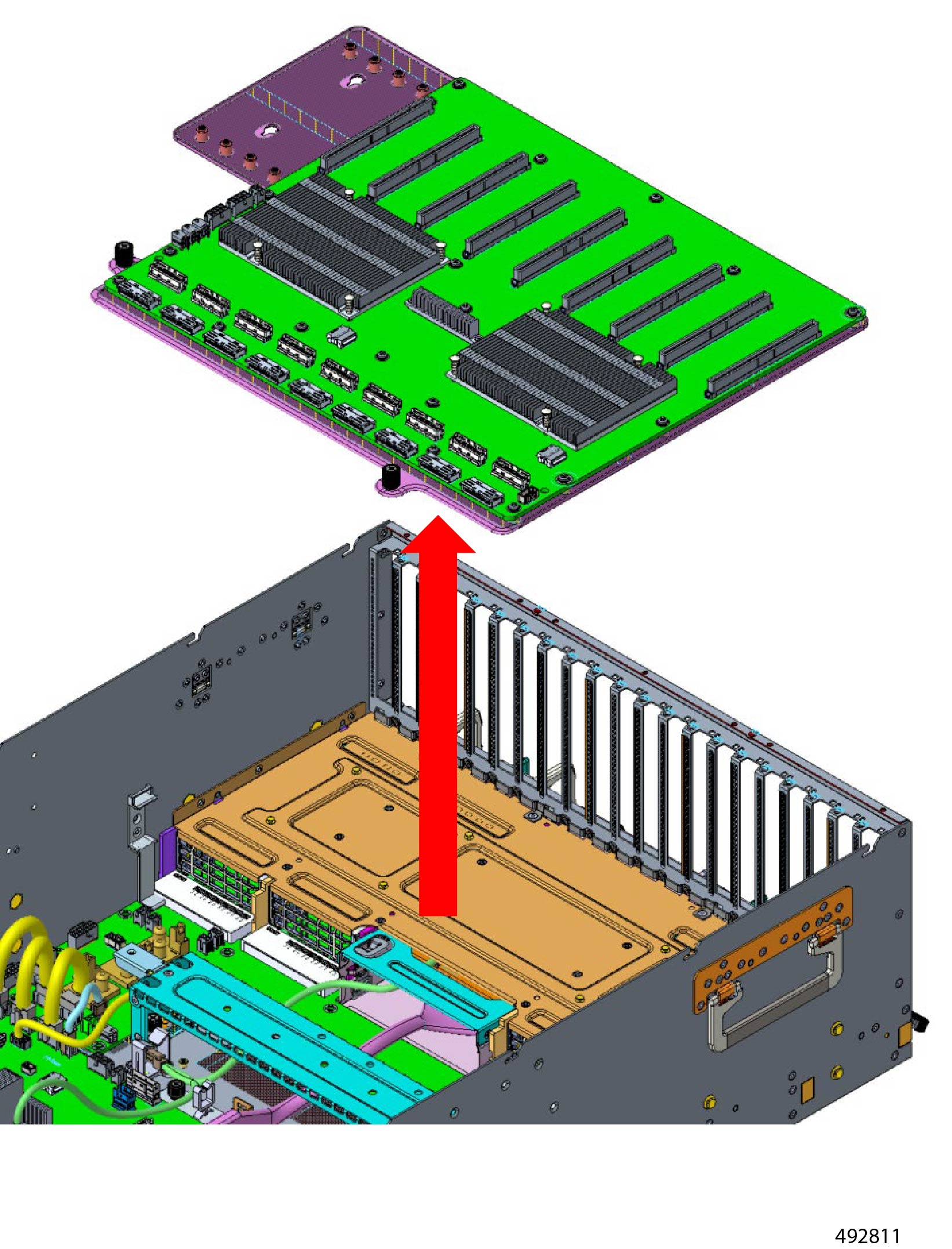
Remove the HSC Board.
-
Remove the following screws.
-
Remove the HSC Board, but sliding it forward then lifting it out of the chassis.
|
|
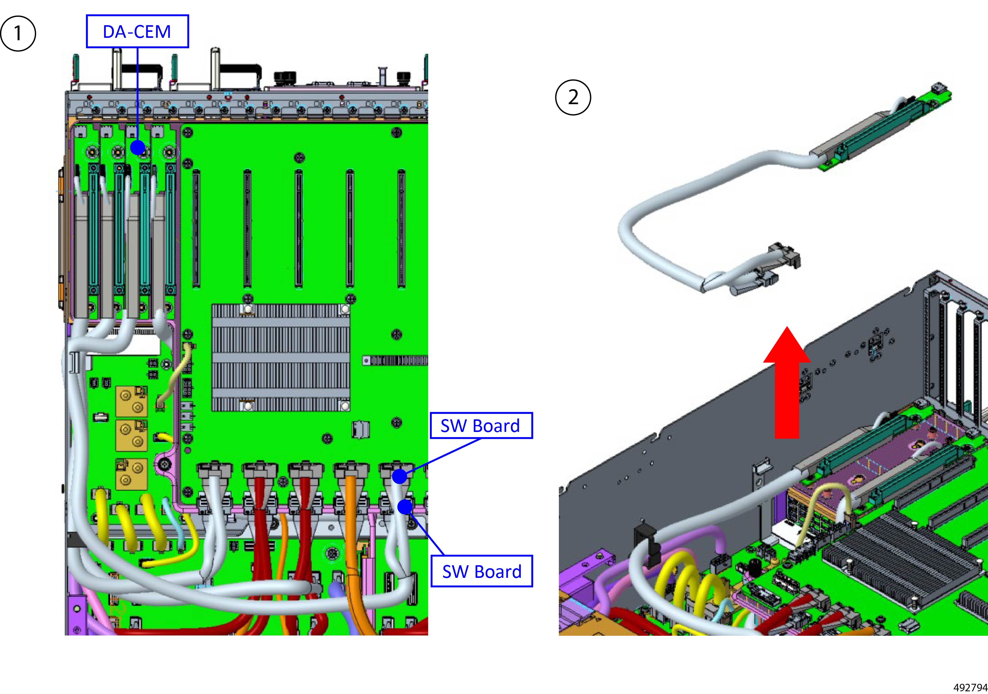
Step 9
|
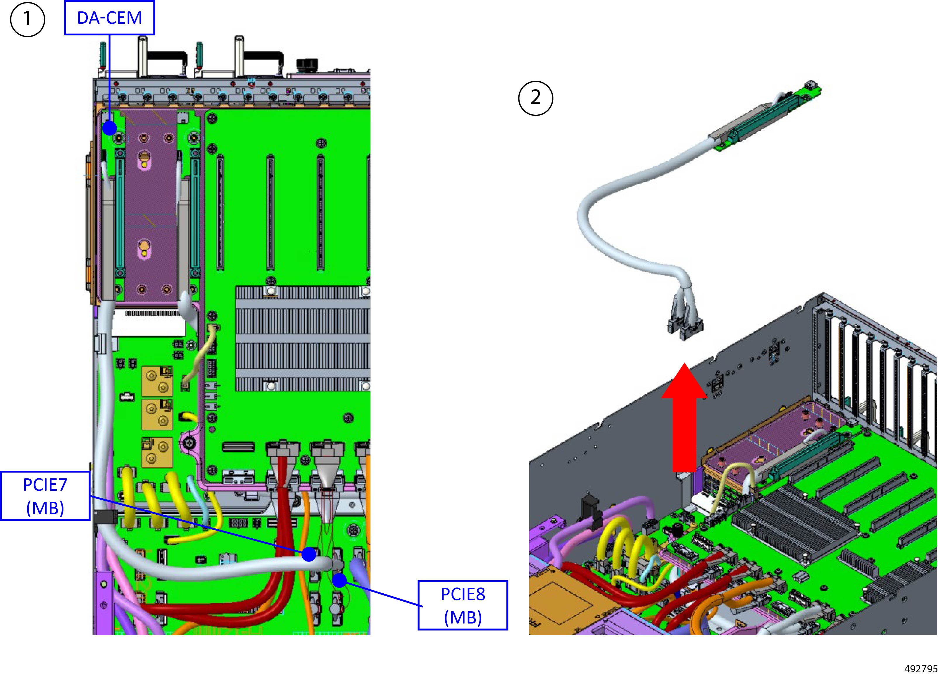
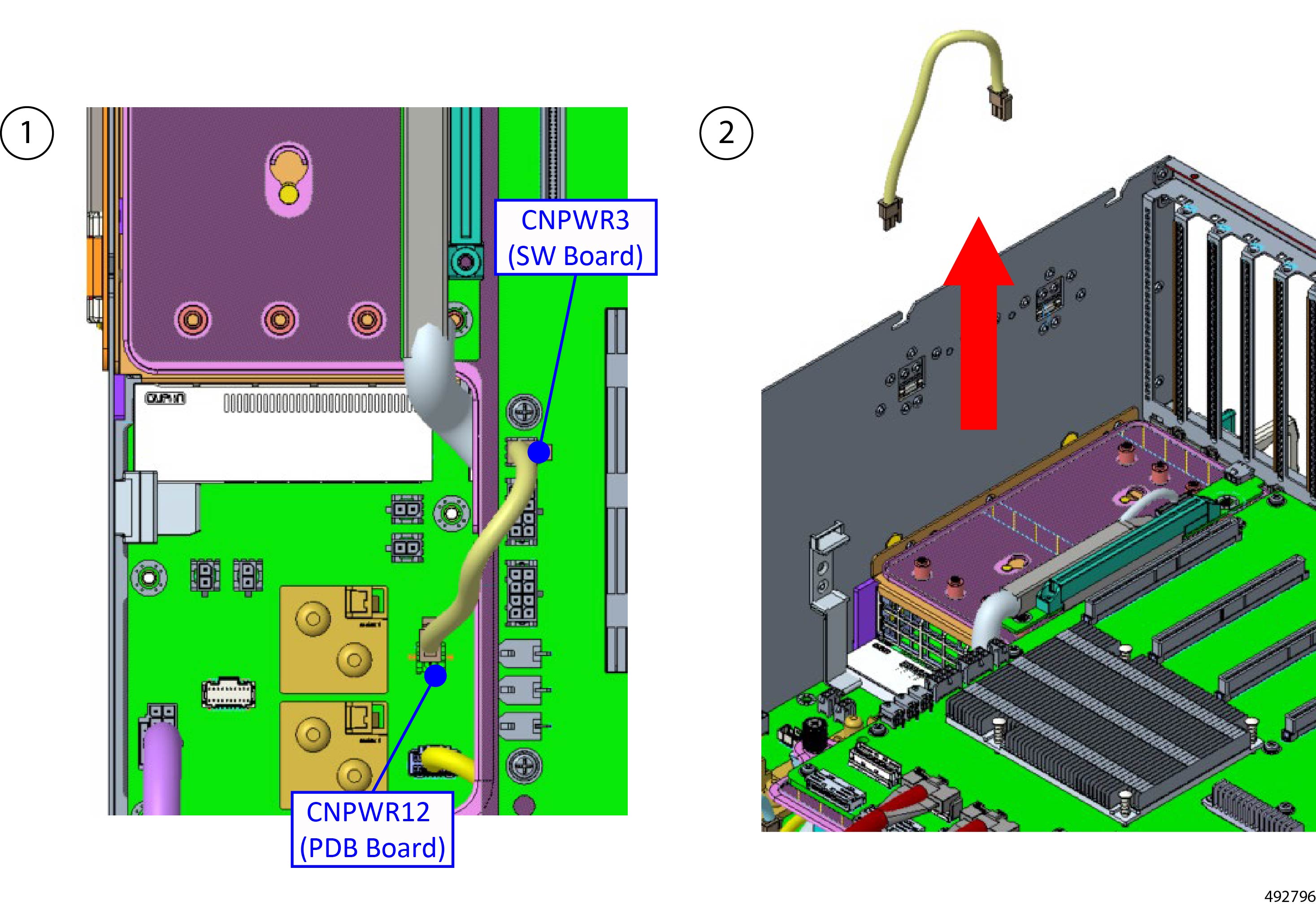
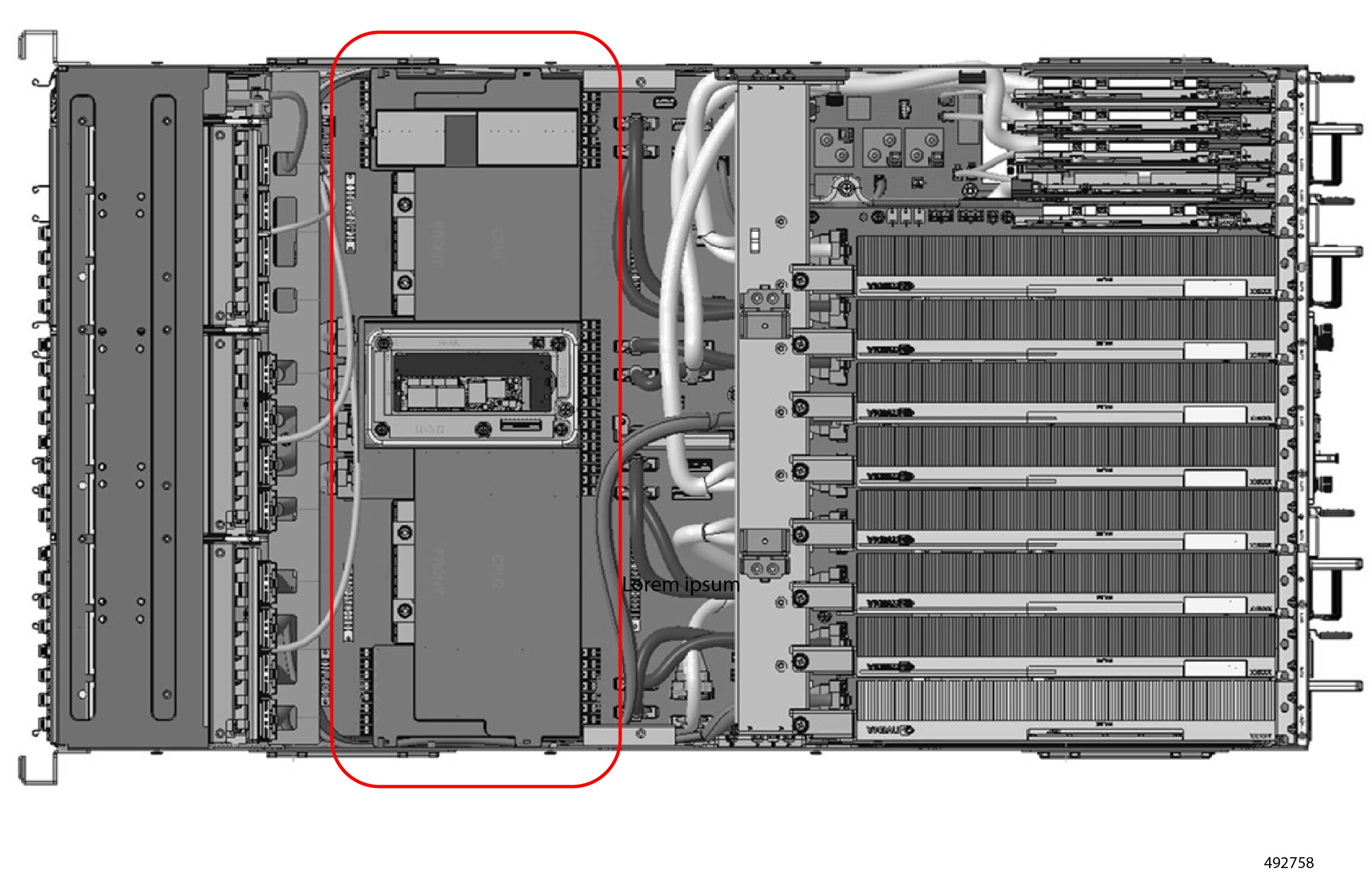
Remove the DA-CEM.
-
Locate and remove the power cables from the DA-CEM and the PDB board.
-
Using a #2 Phillips screwdriver, remove the eight screws.
-
Locate and remove the Y cables (ConnectX-7 or BlueField3) from the SW Board.
-
Locate and remove the PCIe cables.
-
Locate and remove the power cable from the SW board and PDB board.
|
|
Step 10
|
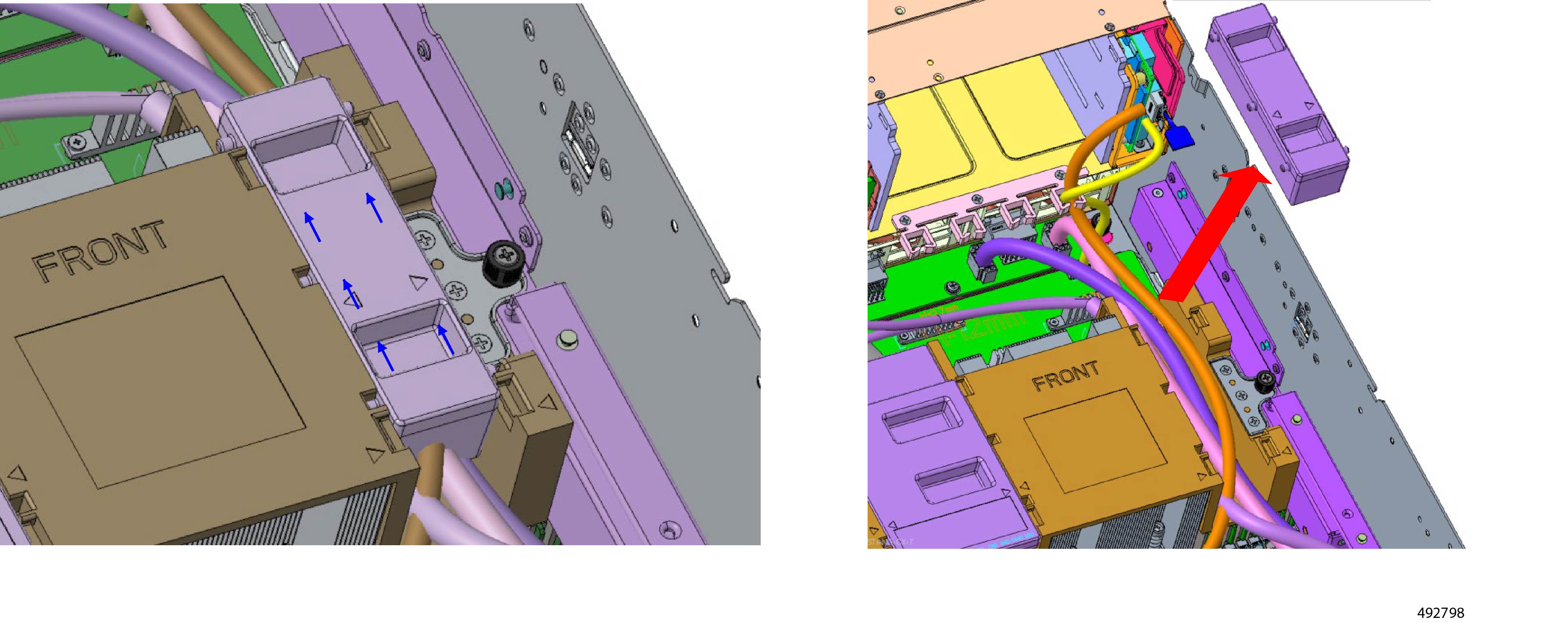
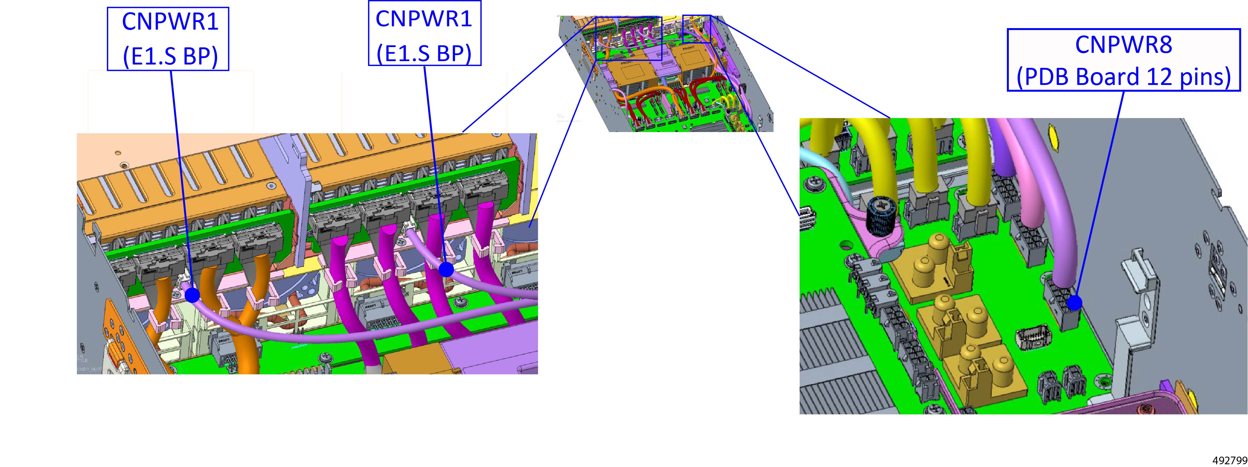
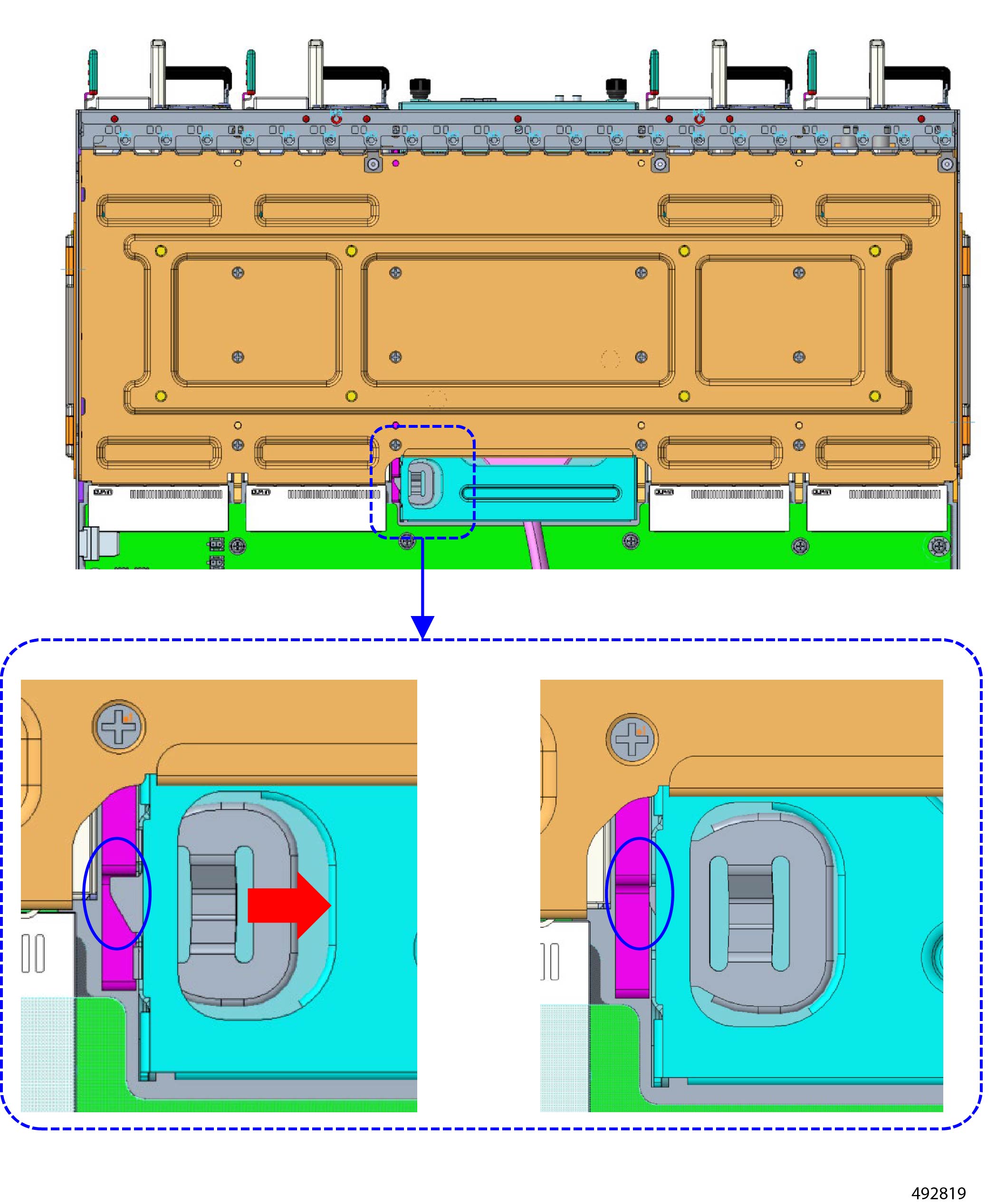
Remove the E1.S cable (right side).
-
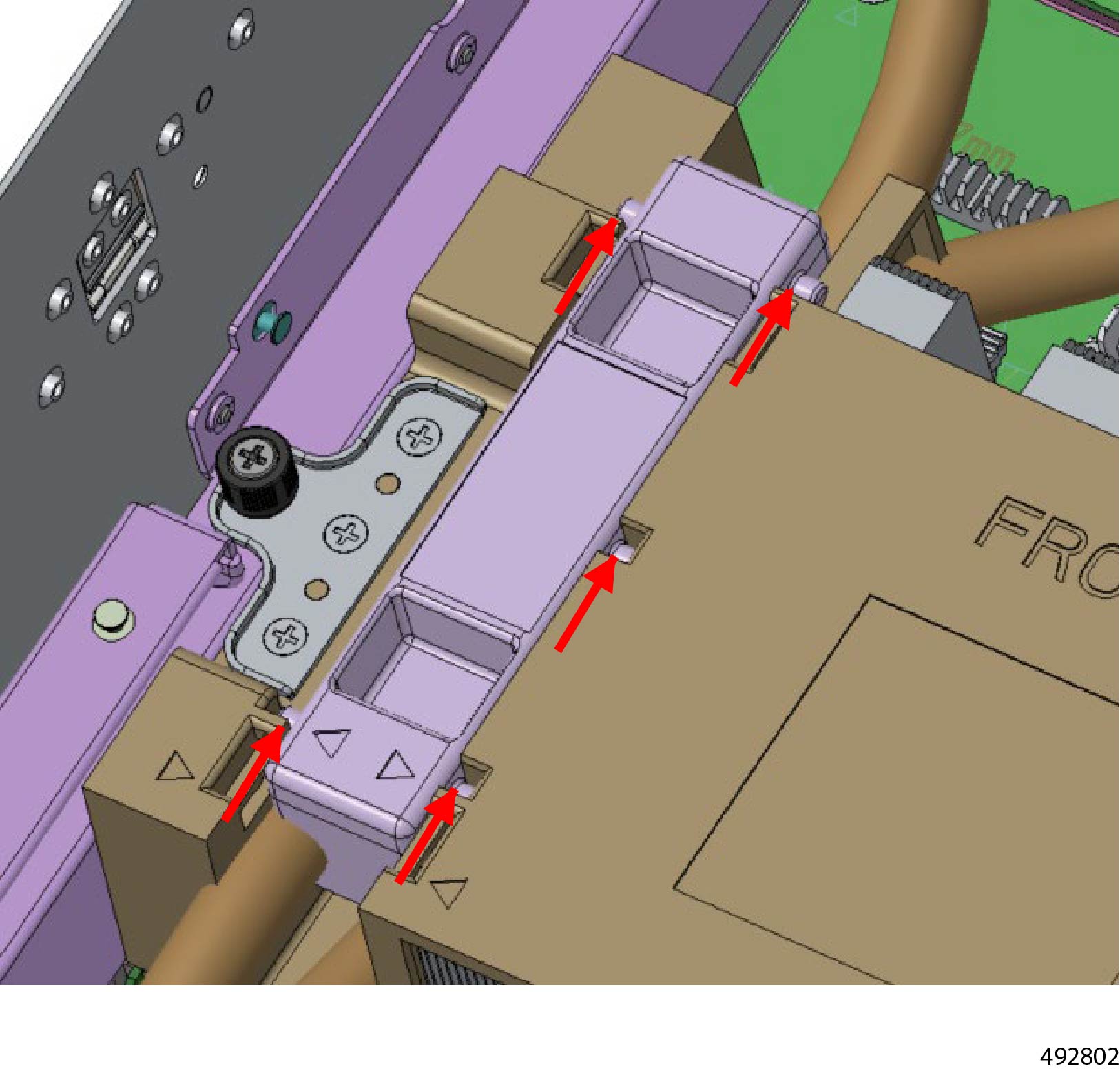
Slide the cable cover until it disengages from the chassis.
-
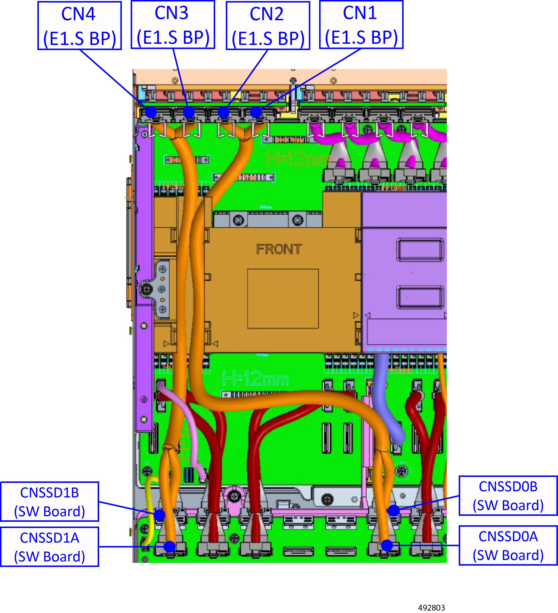
Disconnect the power Y cables from the drive backplane and PDB board.
-
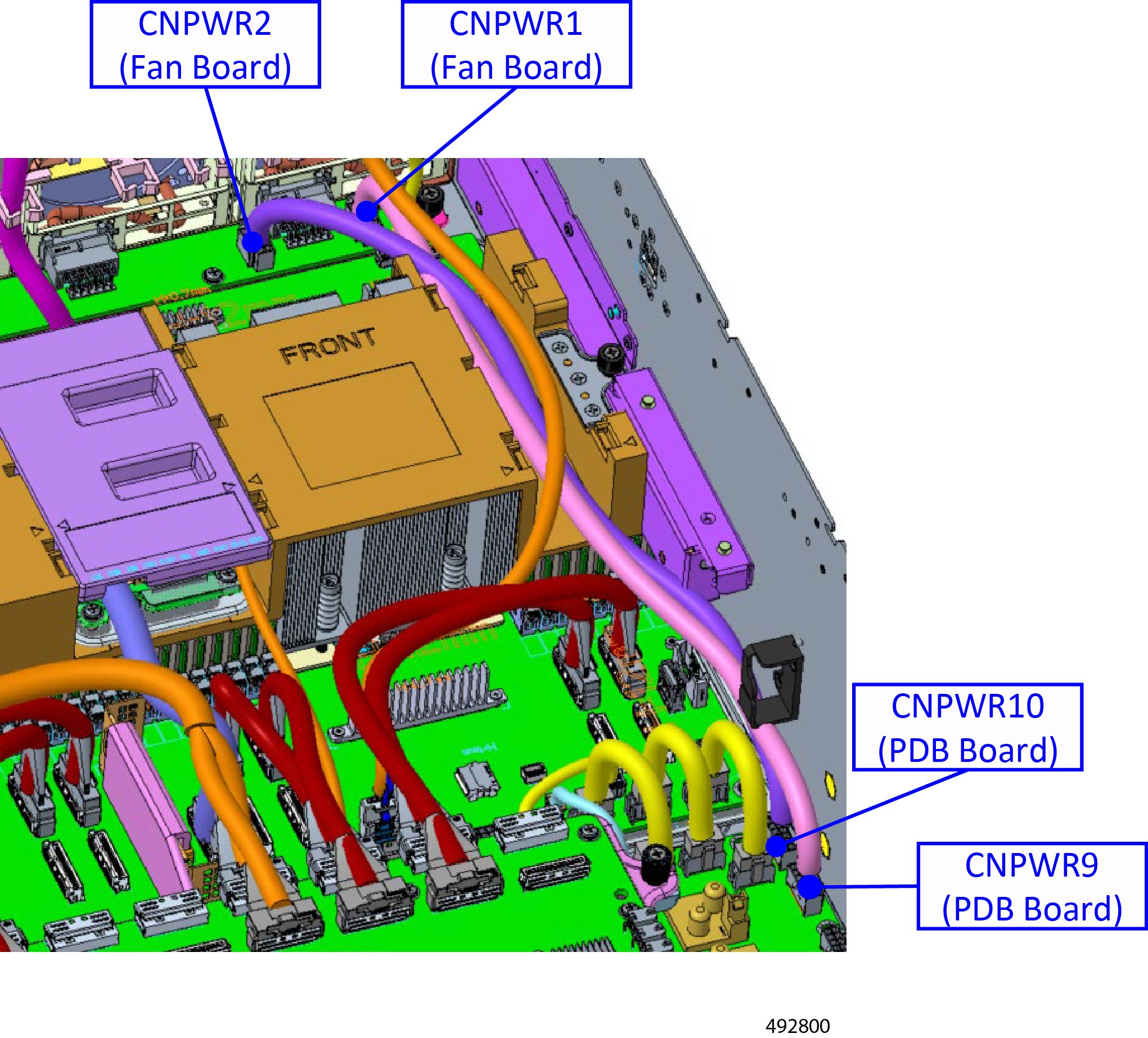
Remove the remaining power cables from the fan board and the PDB board.
-
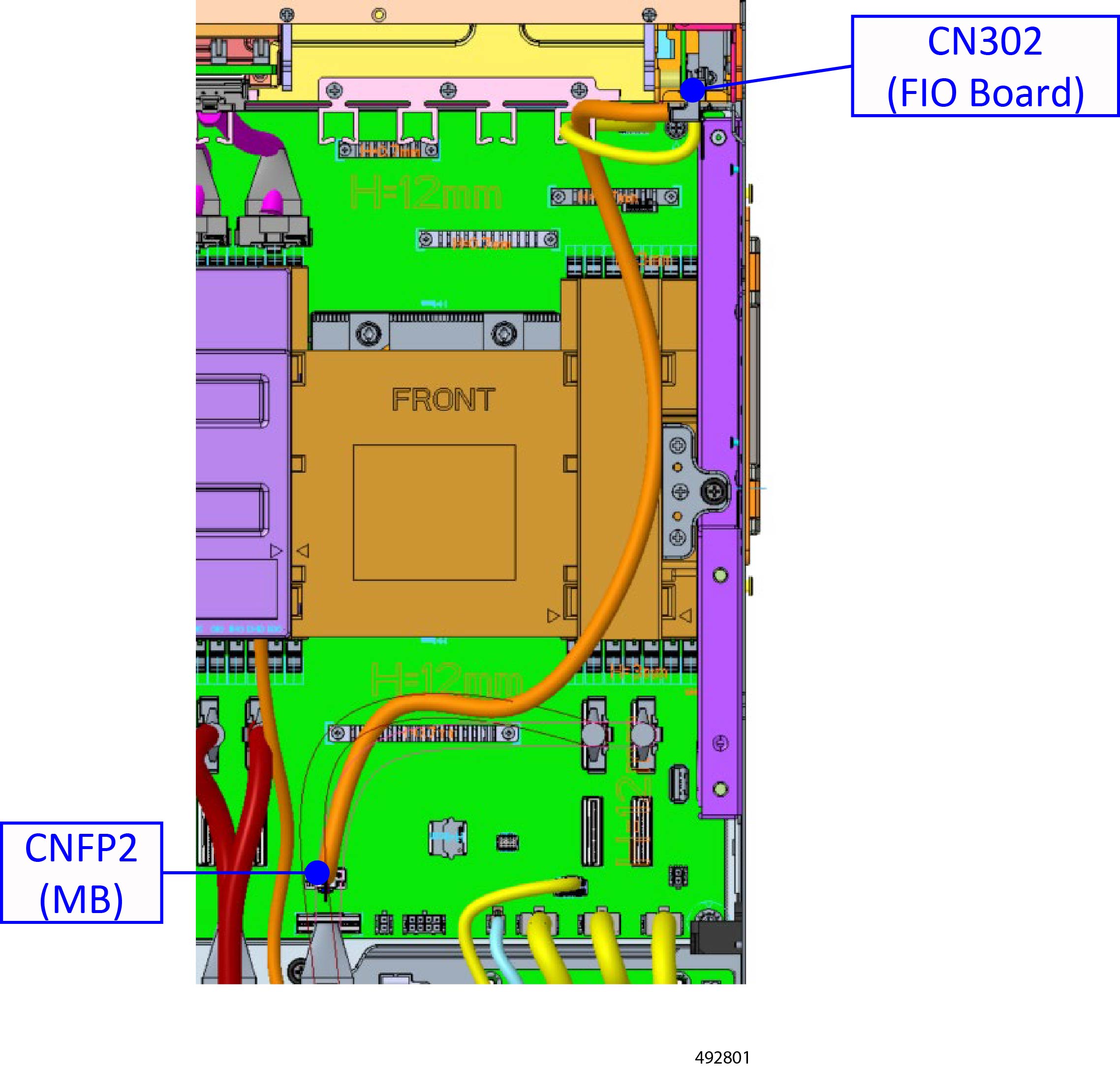
Remove the x4 Slimline FIO cable.
|
|
Step 11
|
Remove the E1.S cable (left side).
-
Slide the cable cover until it disengages from the chassis.
-
Disconnect the two MCIO X cables from the drive backplane and SW board.
|
|
Step 12
|
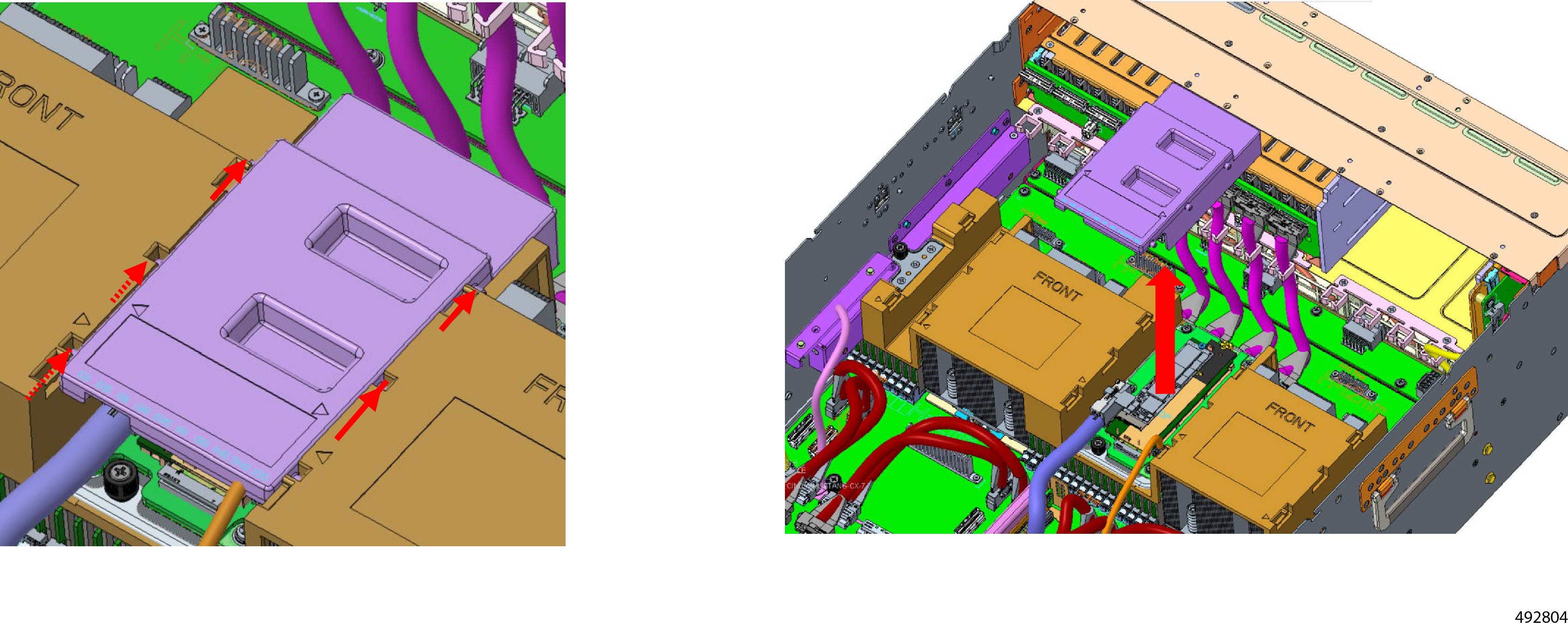
Remove the M.2 cover.
|
|
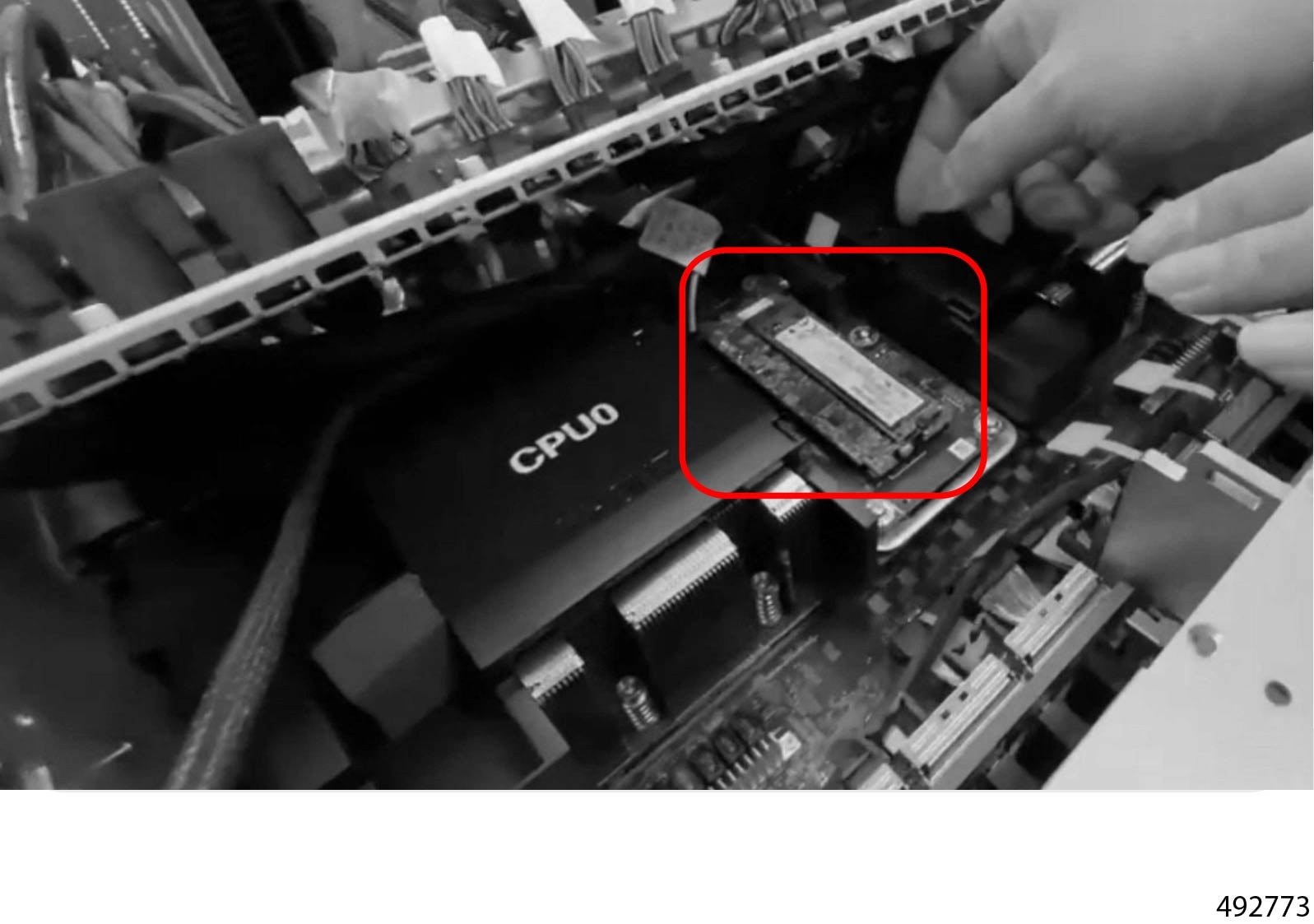
Step 13
|
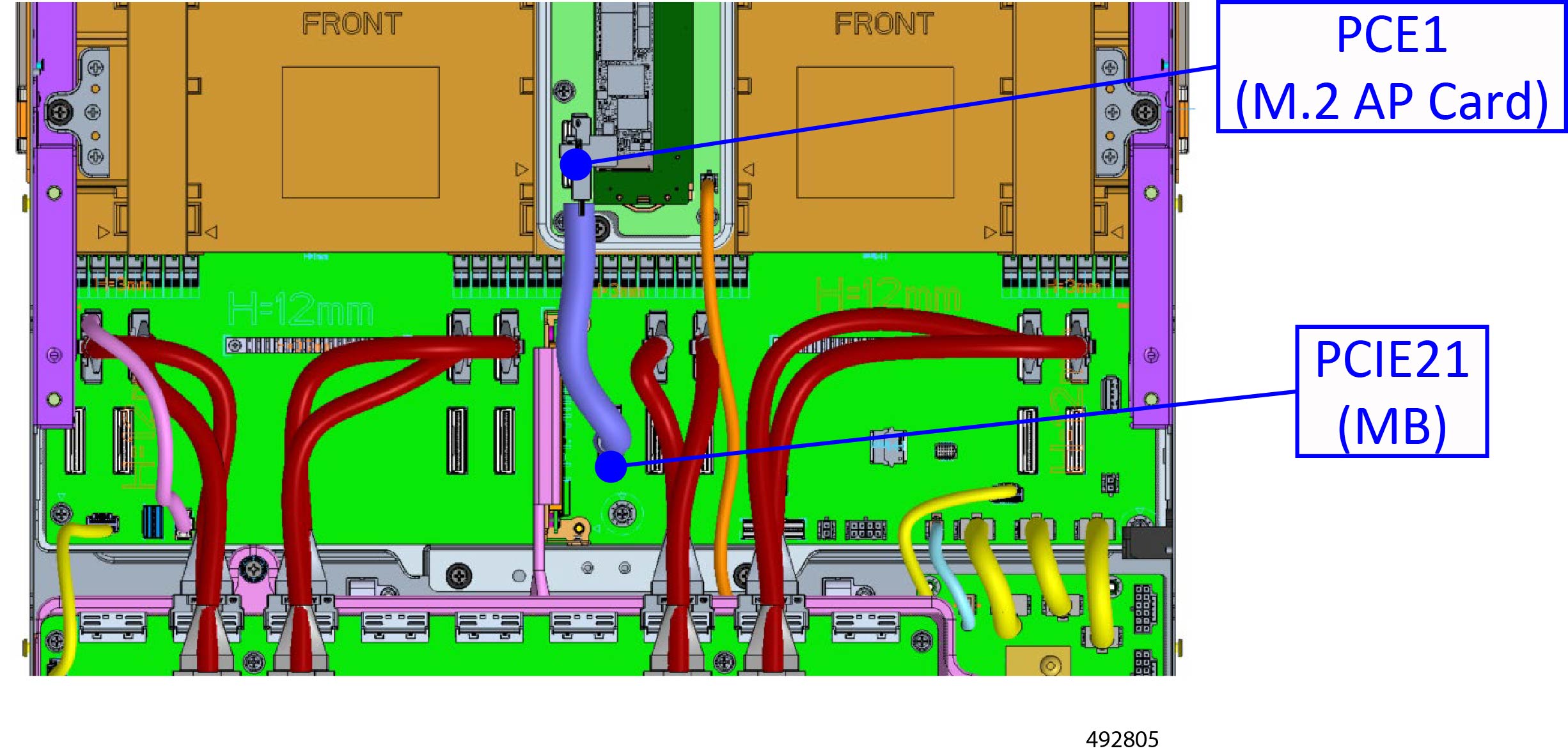
Remove the M.2 card.
-
Disconnect the MCIO cable from the M.2 adapter card.
Although not required, you can disconnect it from the motherboard also.
-
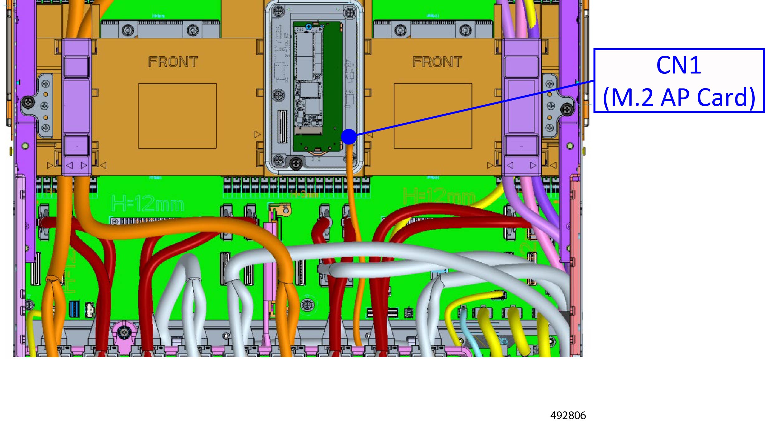
Remove the following power cable from the M.2 adapter card.
Although not required, you can disconnect it from the motherboard also.
|
|
Step 14
|
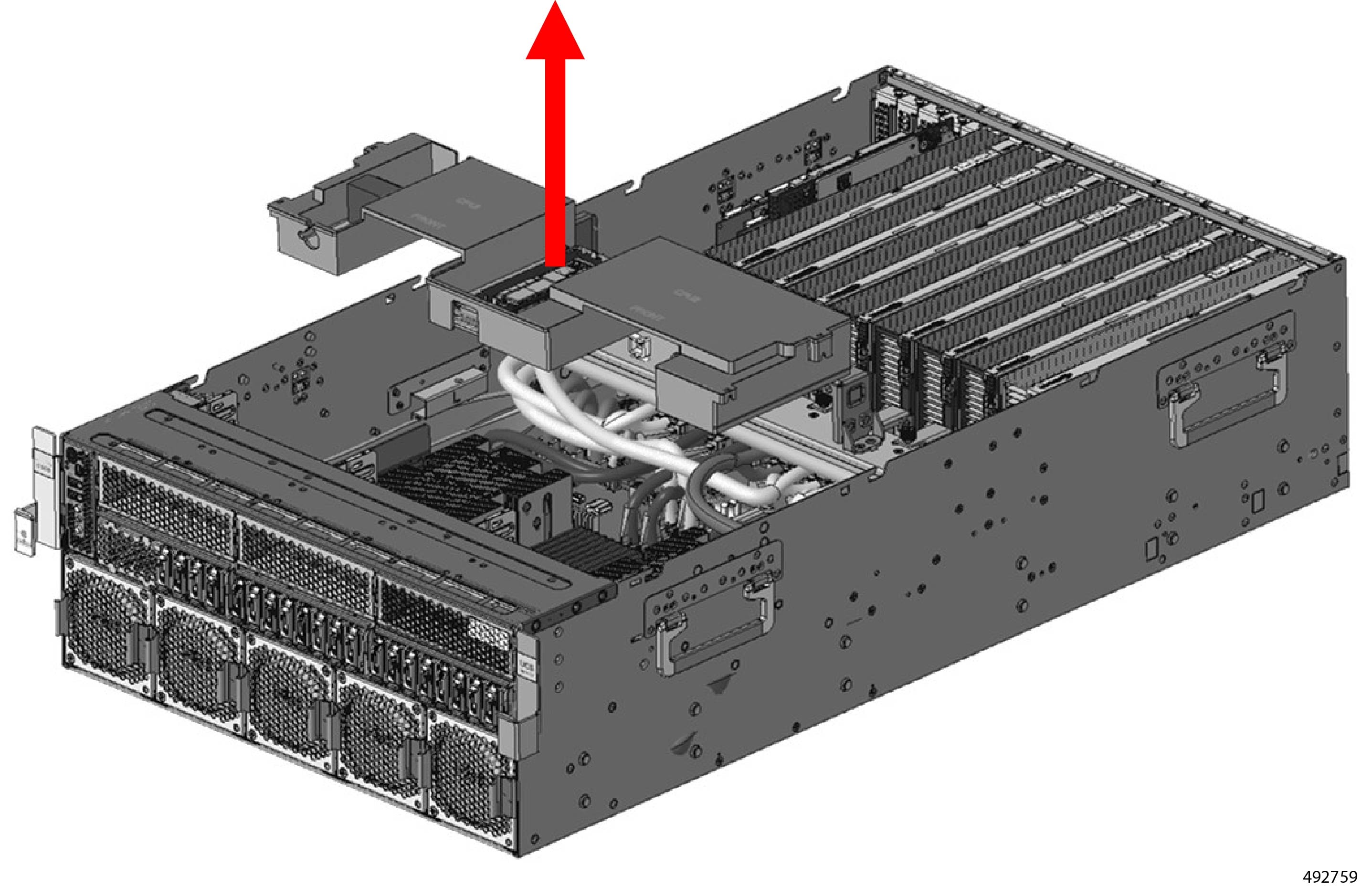
Remove the air duct.
-
Using a #2 Phillips screwdriver, remove the two captive screws on the air duct.
One screw is at each end of the air duct, near each chassis sidewall.
-
Slide the air duct until it clears the T pins.
-
Lift the air duct up, keeping it level so that the M.2 adapter card stays in place.
|
|
Step 15
|
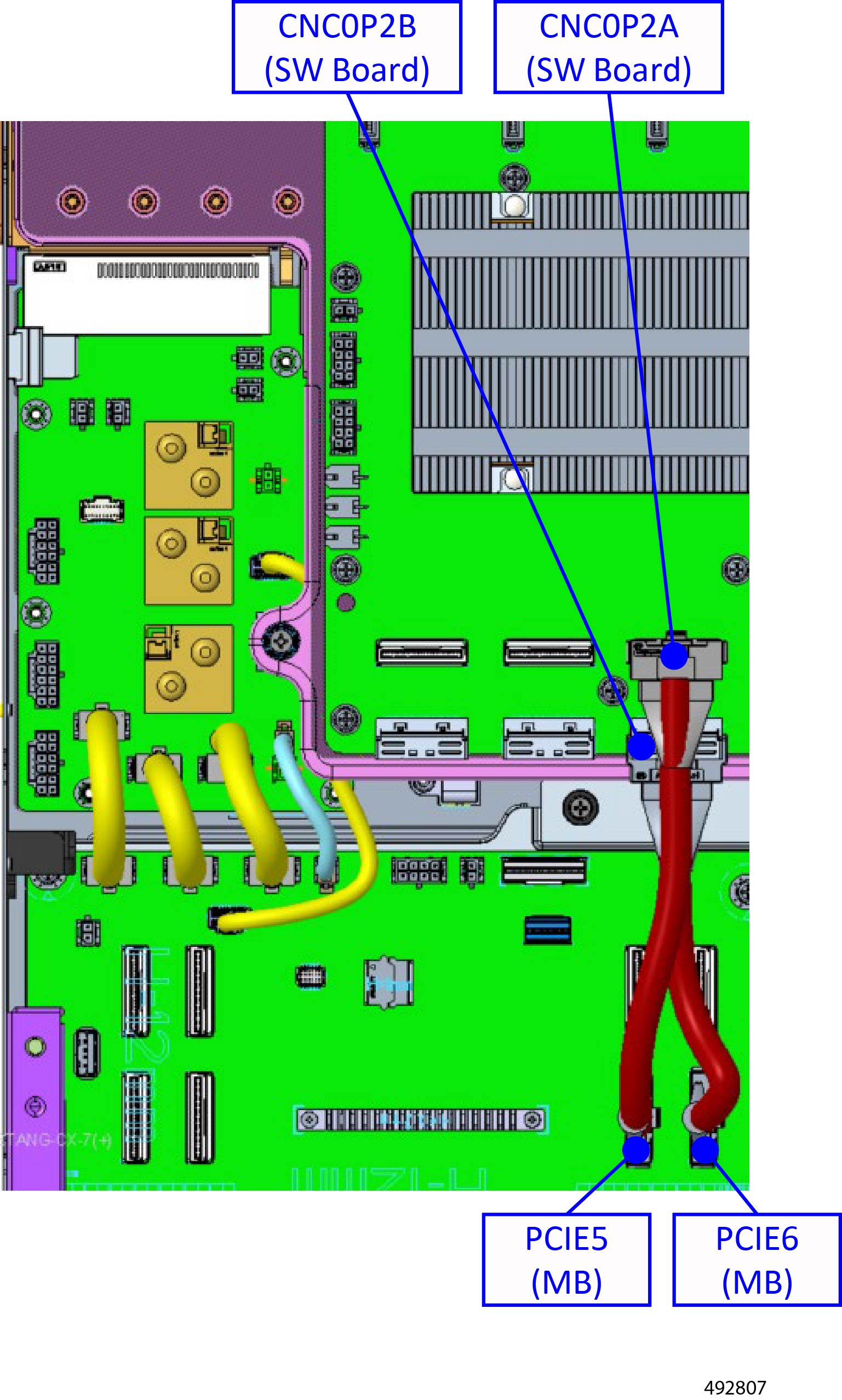
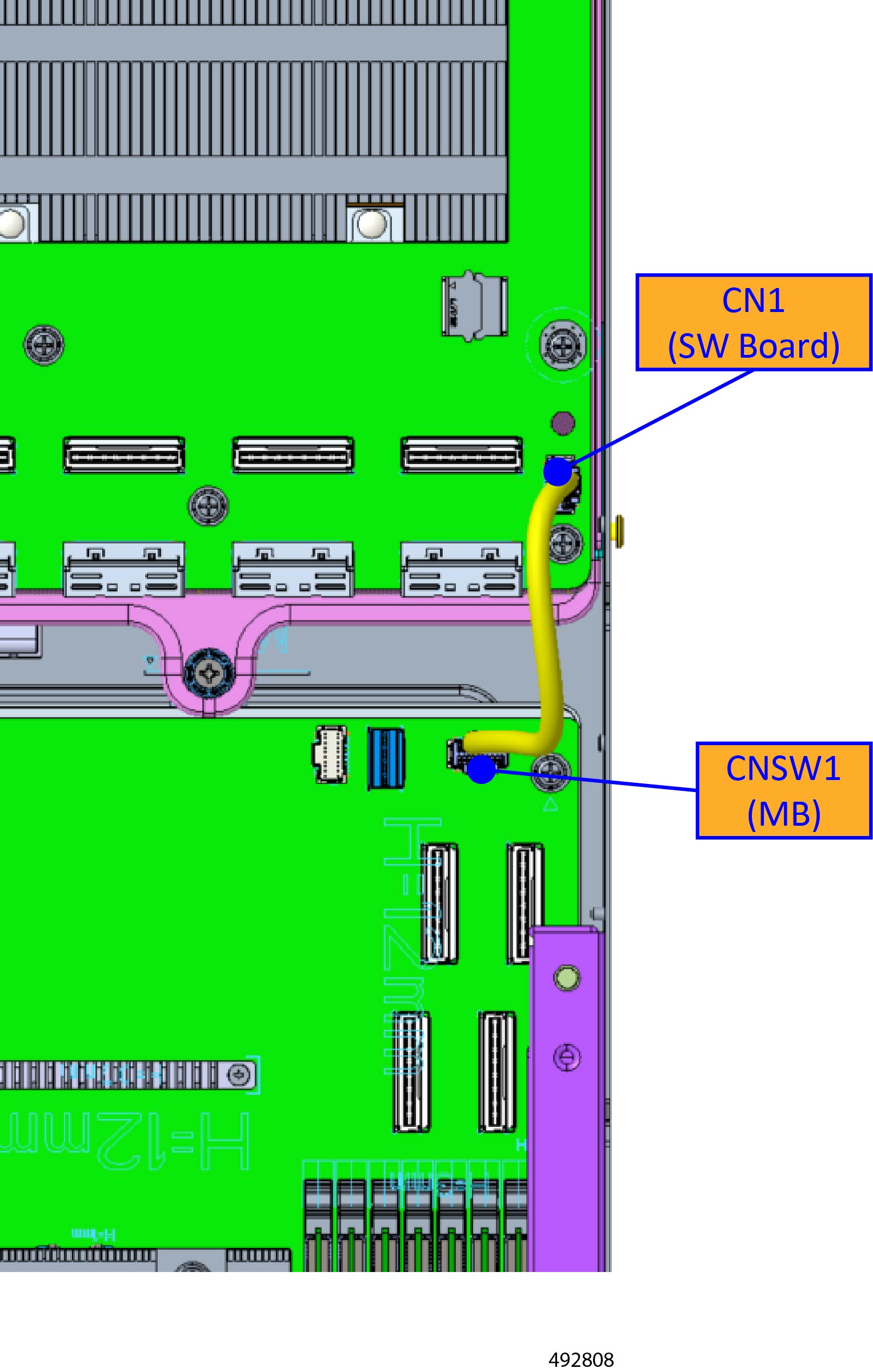
Remove the SW Board.
-
Remove the two MCIO cables from the motherboard and SW Board.
The cable connected to CNC0P2A and CNC0P2B is shown, but disconnect the cables connected to CNC0P0A and CNC0P0B, CNC1P0A and
CNC1P0B, and CNC1P2A and CNC1P2B.
-
Remove the CFG cable from the motherboard and SW board.
-
Using a #2 Phillips screwdriver, remove the two SW Board thumbscrews.
-
Remove the board by sliding it forward until it clears the T pins.
-
Lift the SW Board from the chassis.
|
|
Step 16
|
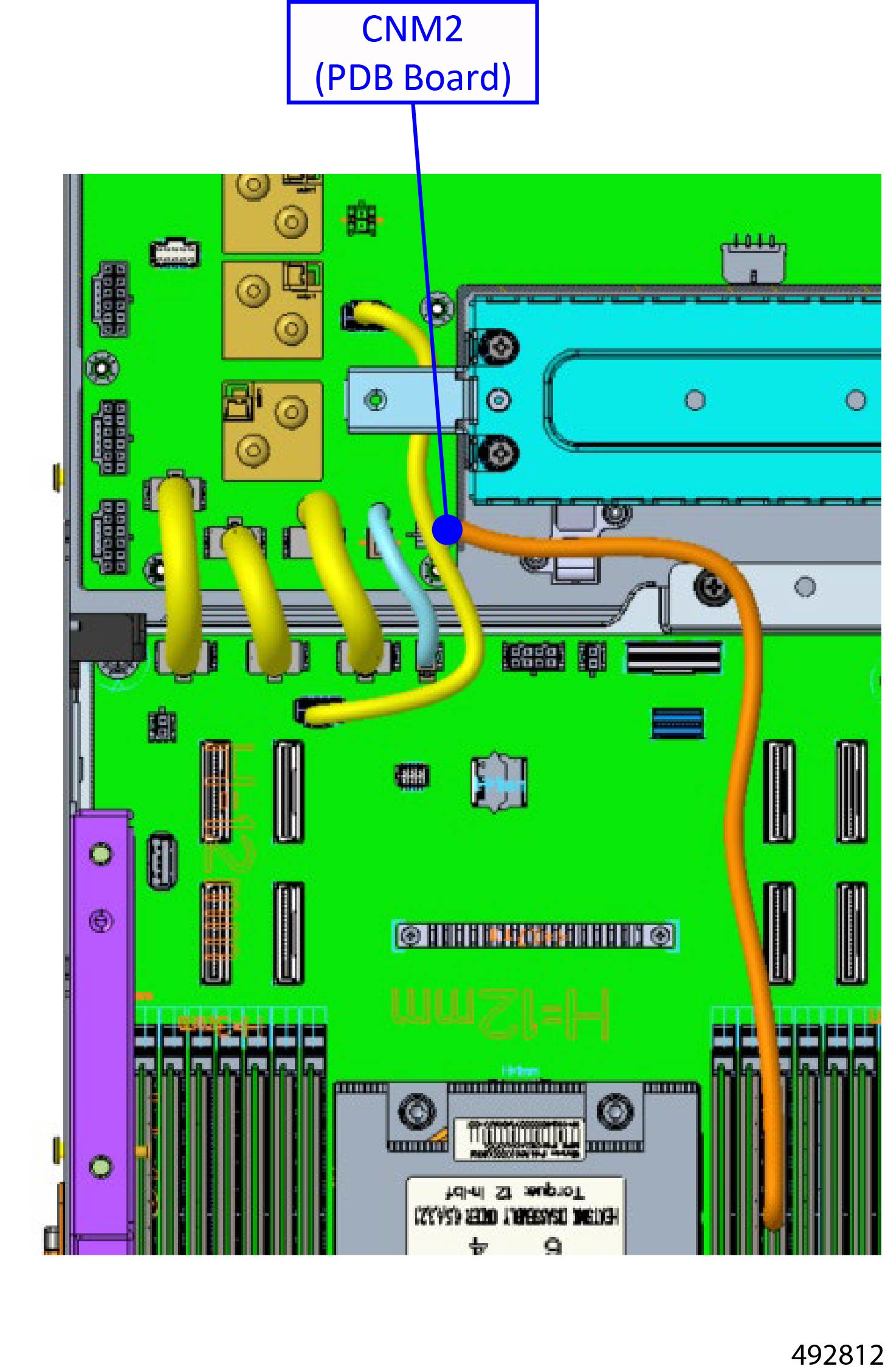
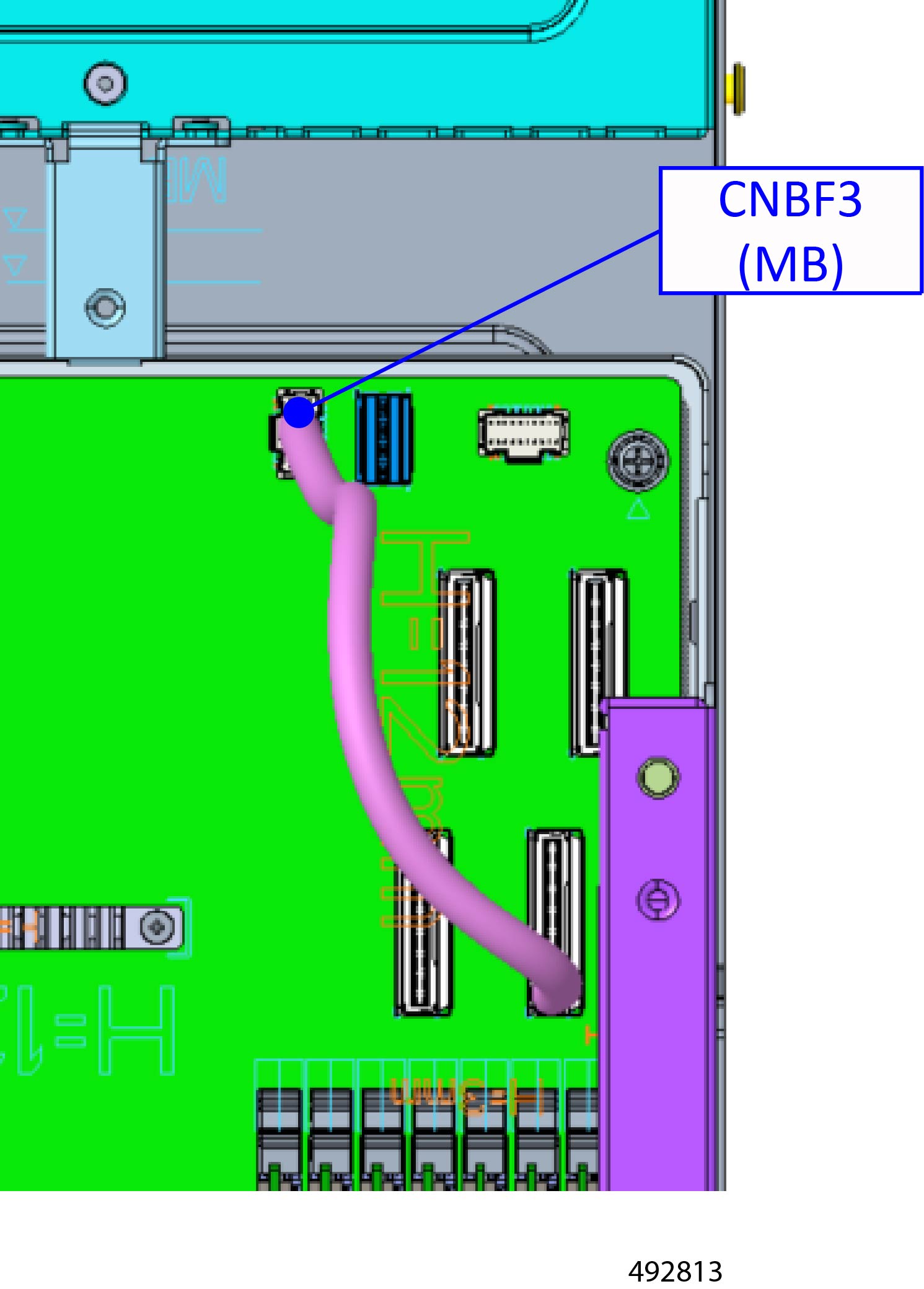
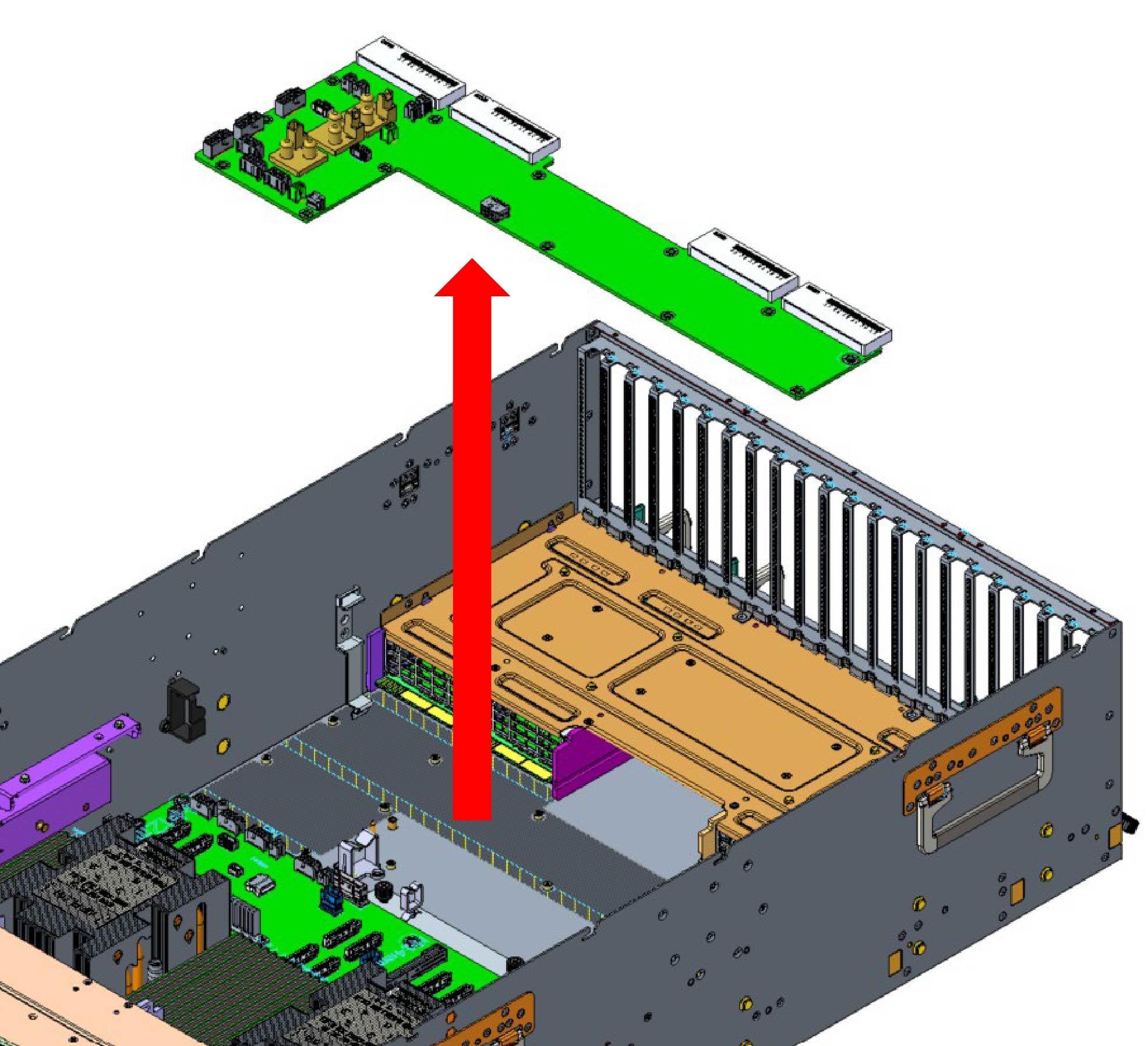
Remove the PDB board.
-
Disconnect the following cable.
-
Remove the following cable.
-
Remove the following cables.
|
|
Step 17
|
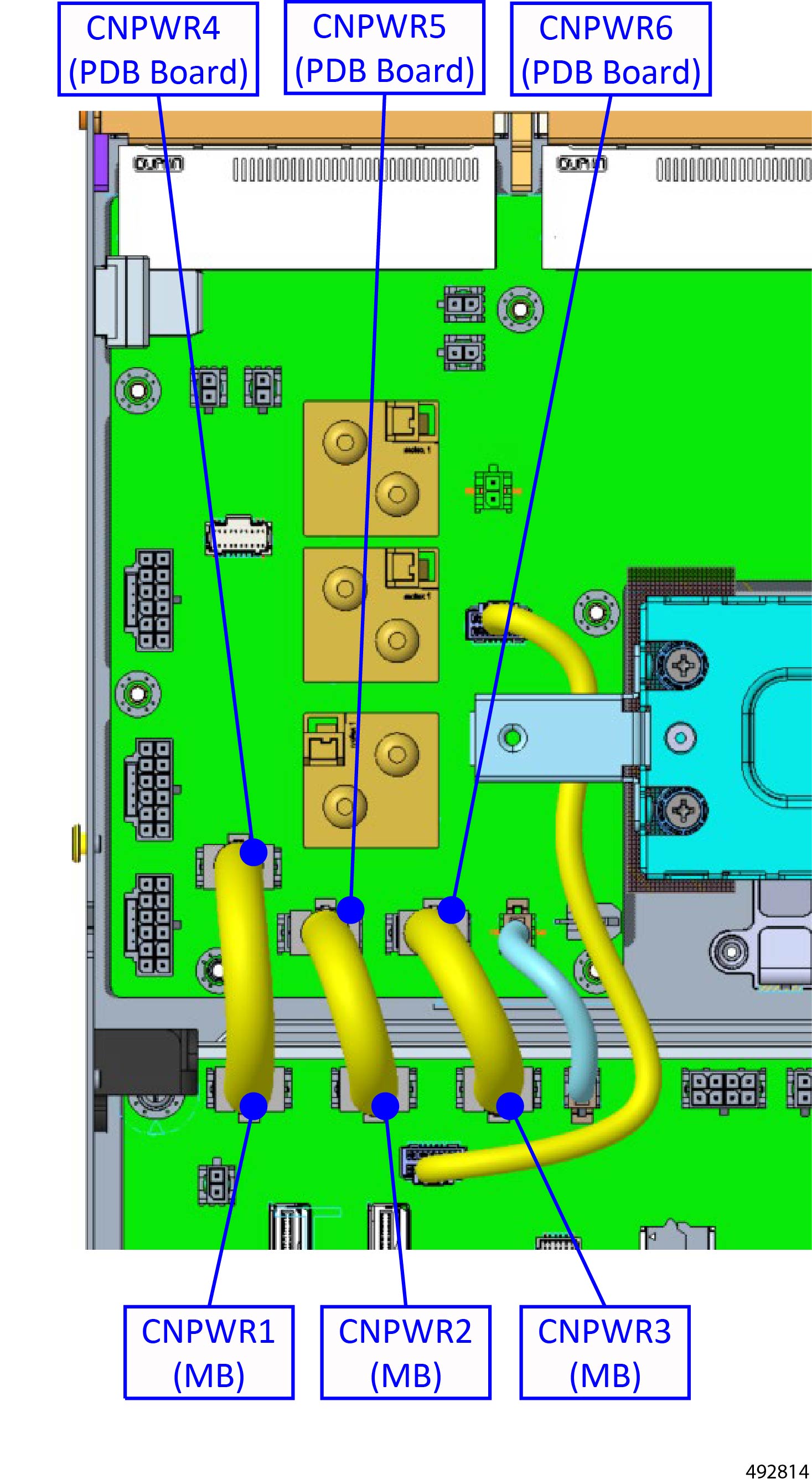
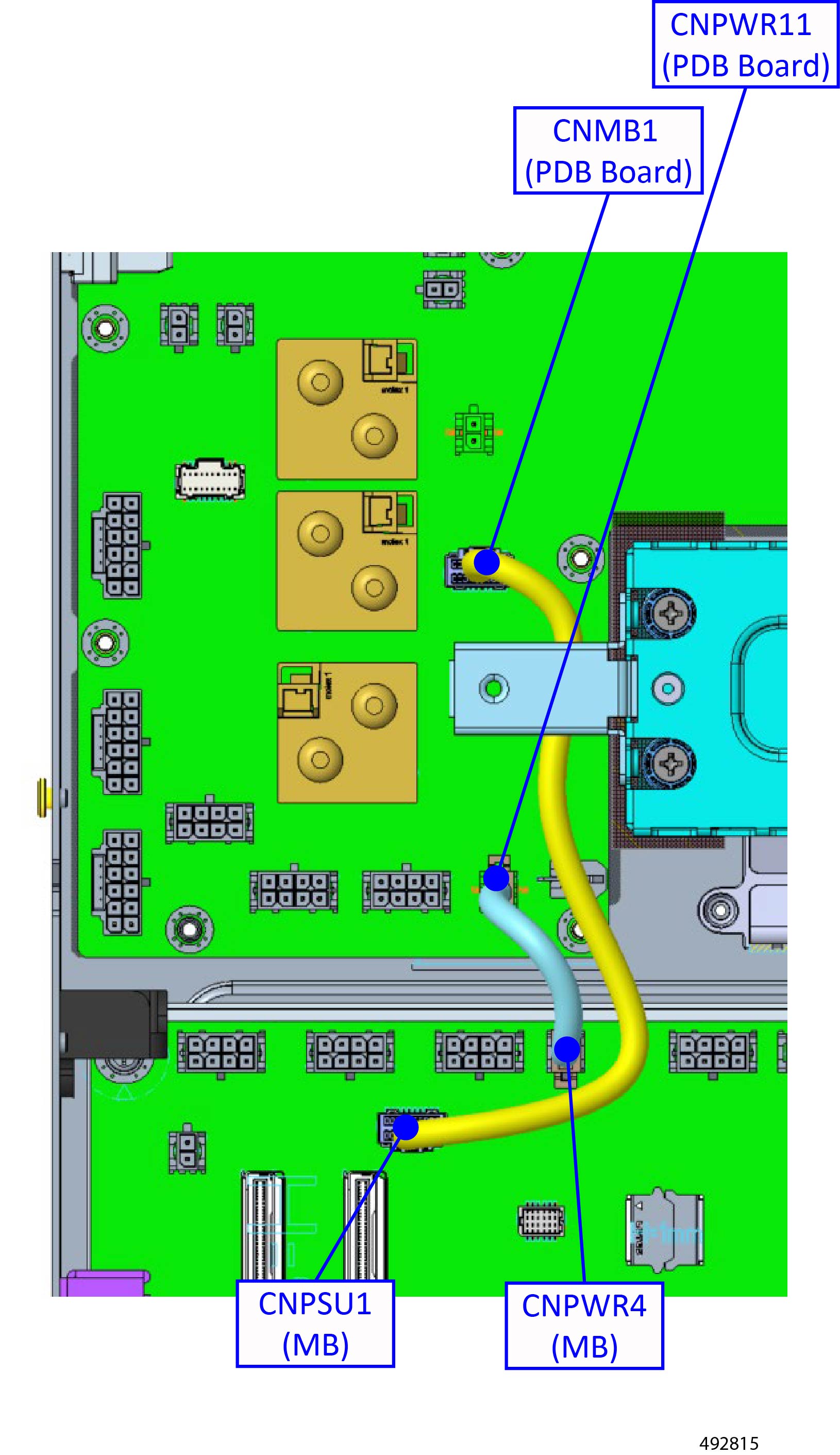
Remove the following cables.
|
|
Step 18
|
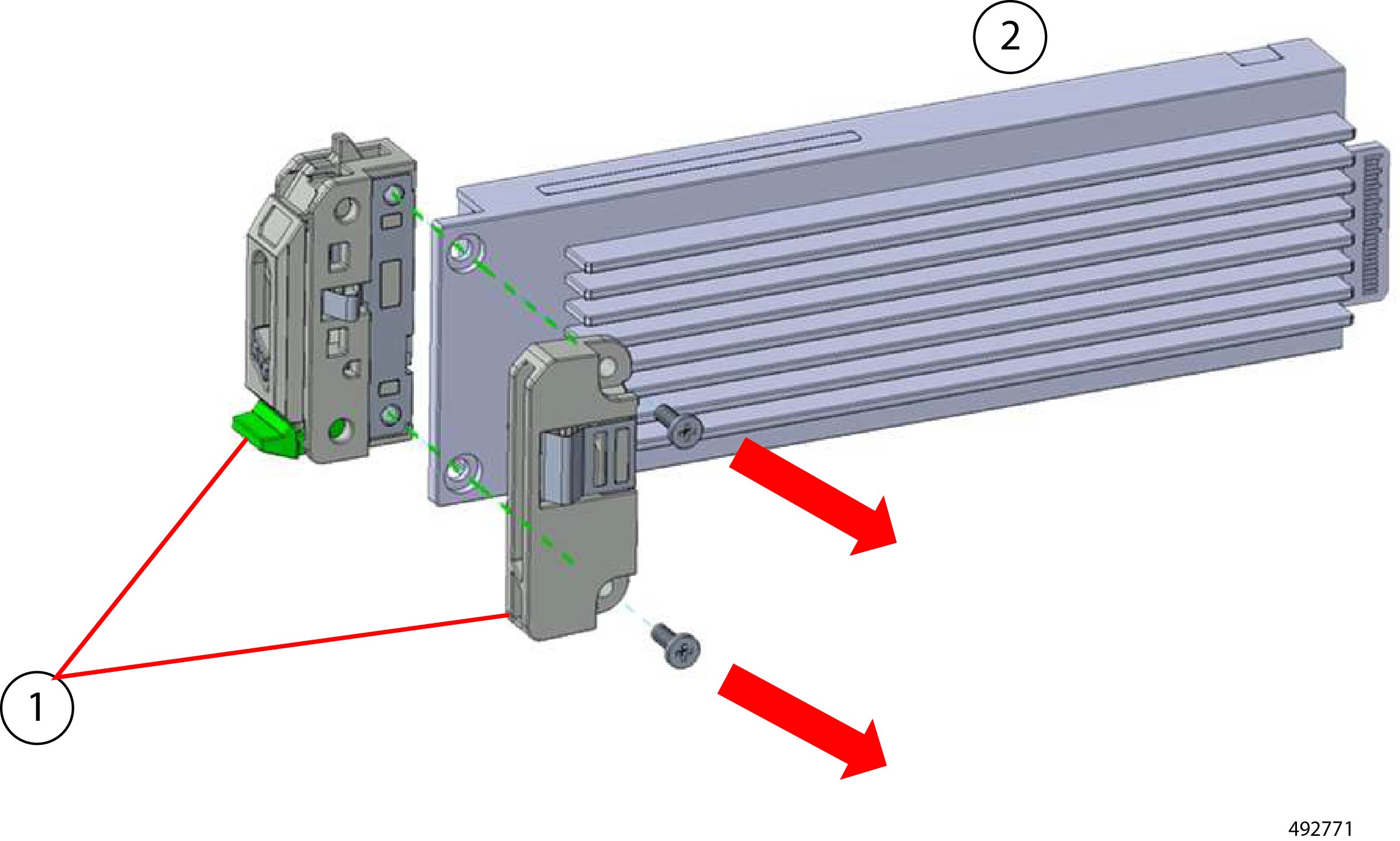
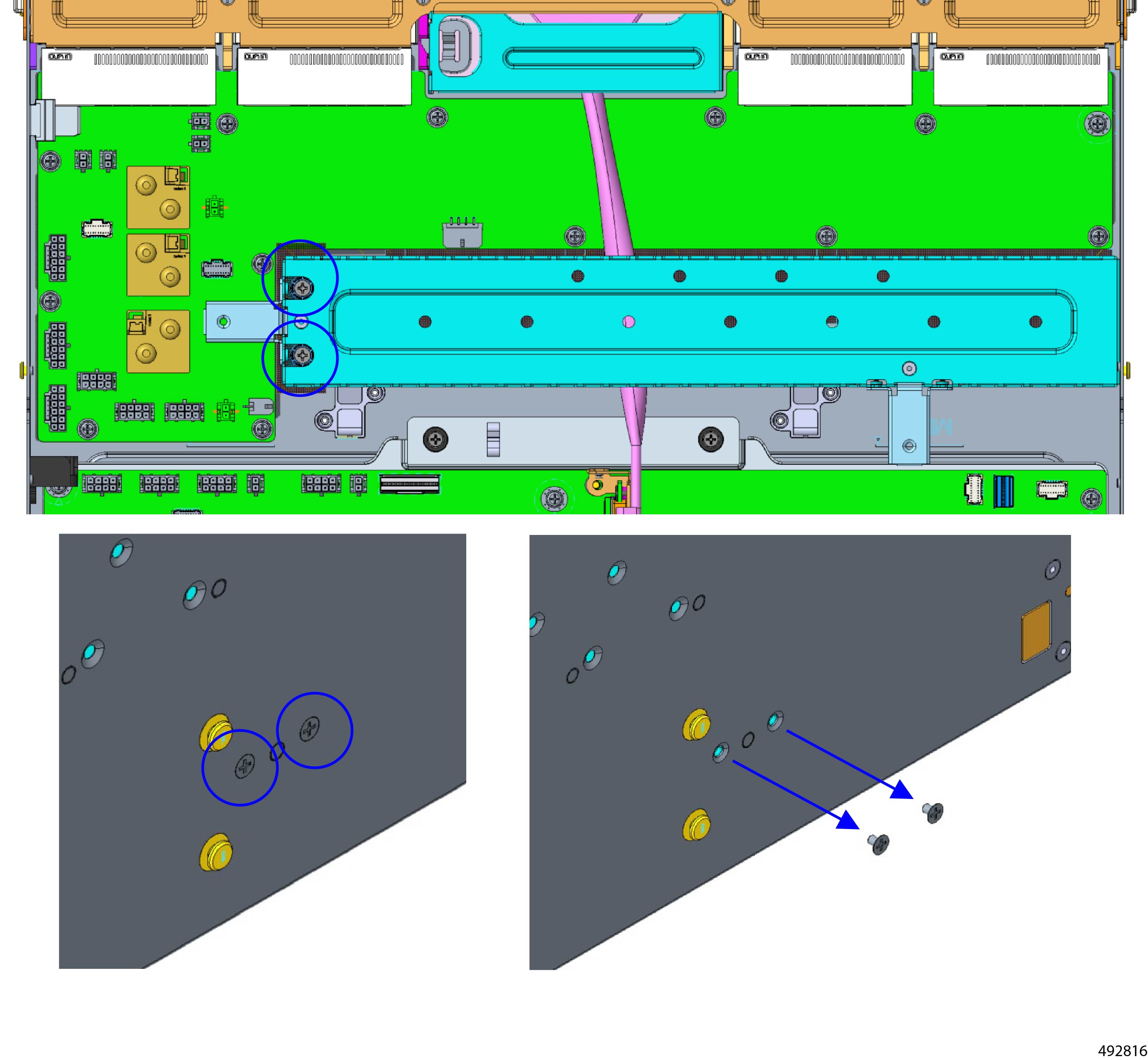
Remove the mid-support bracket.
|
|
Step 19
|
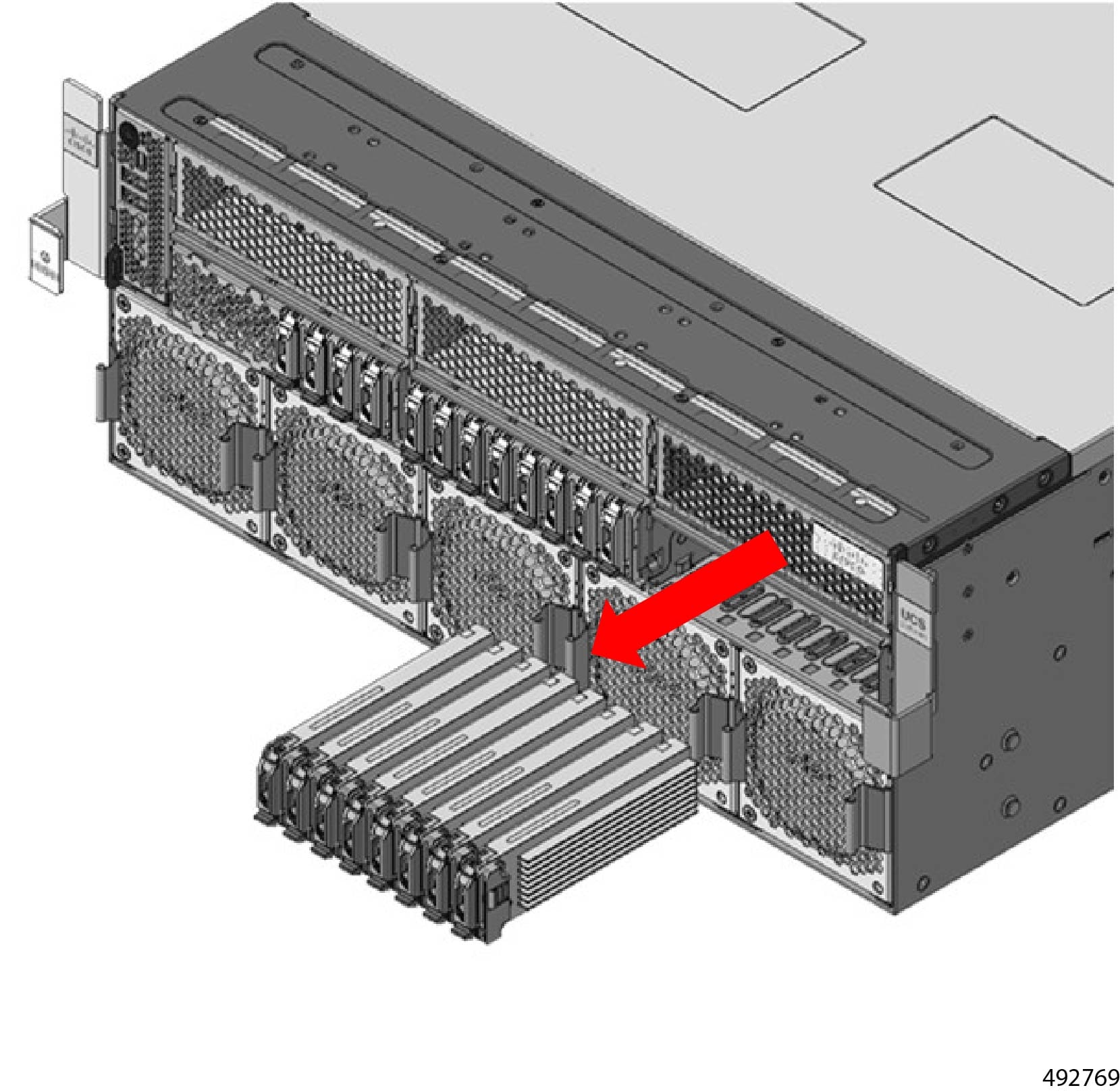
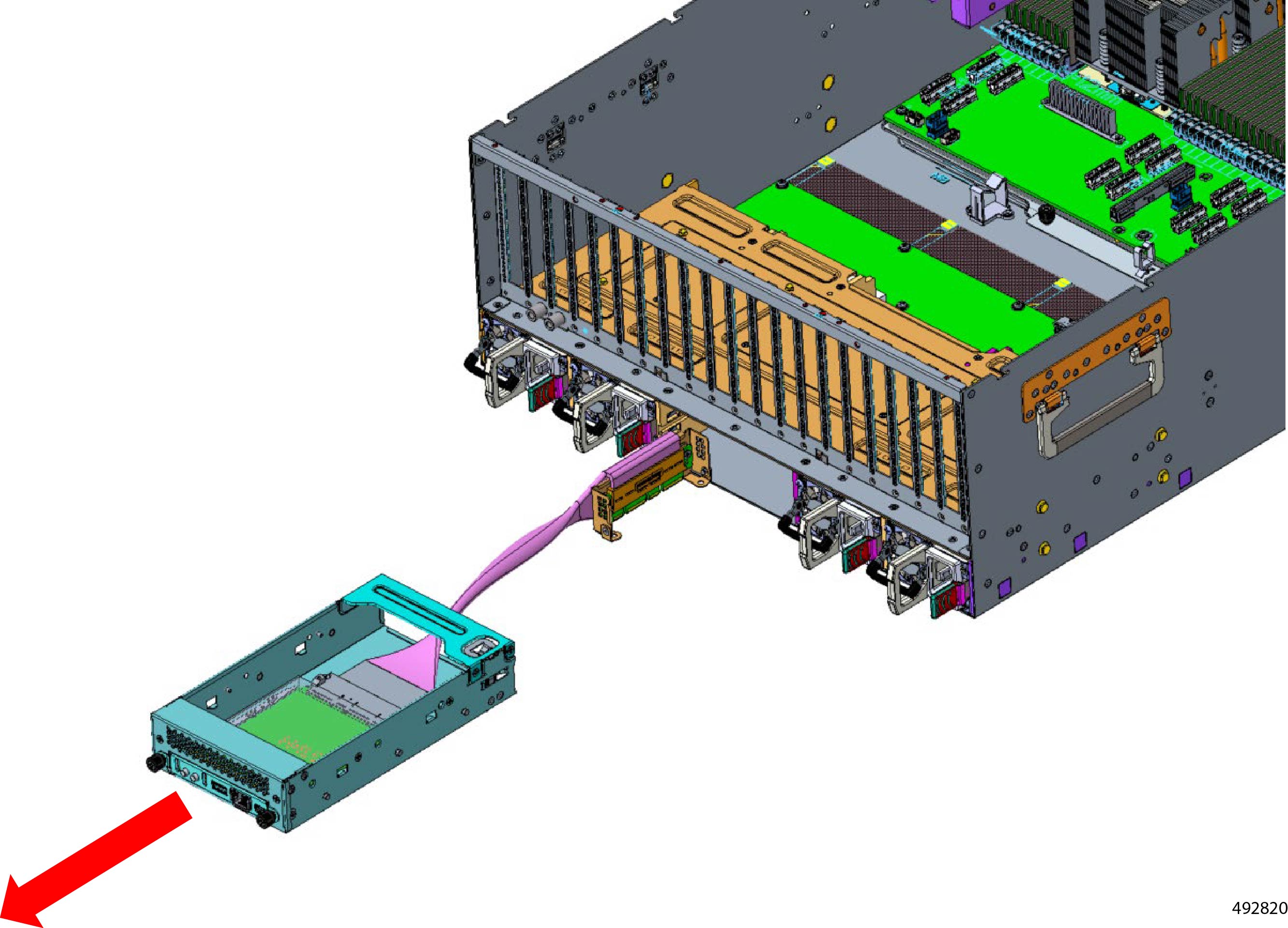
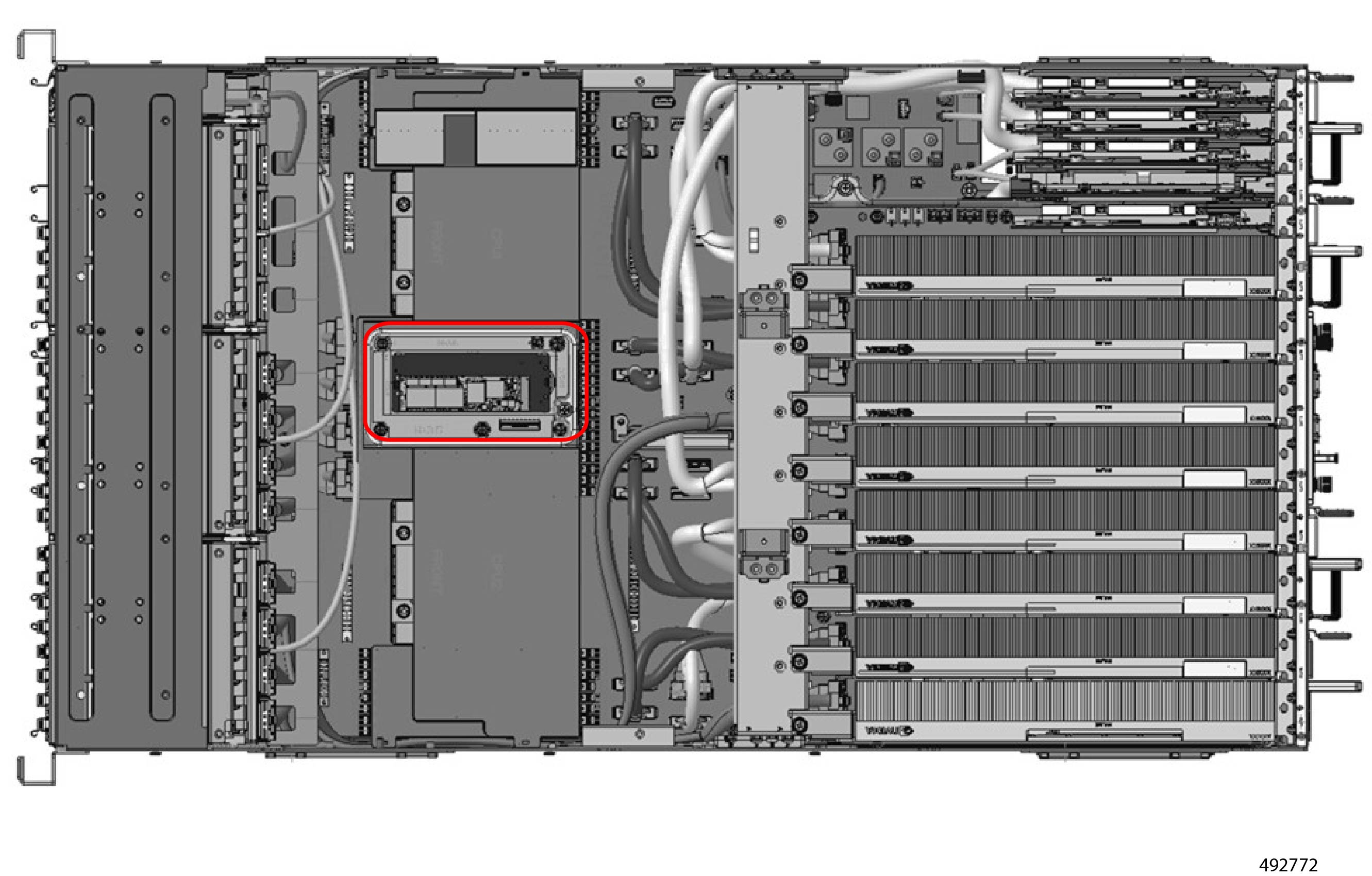
Remove the DC-SCM module.
-
Locate and remove the cable's screws.
-
Disconnect the cable.
-
Remove the DC-SCM cage.
-
Slide the DC-SCM cage out of the server.
|
|
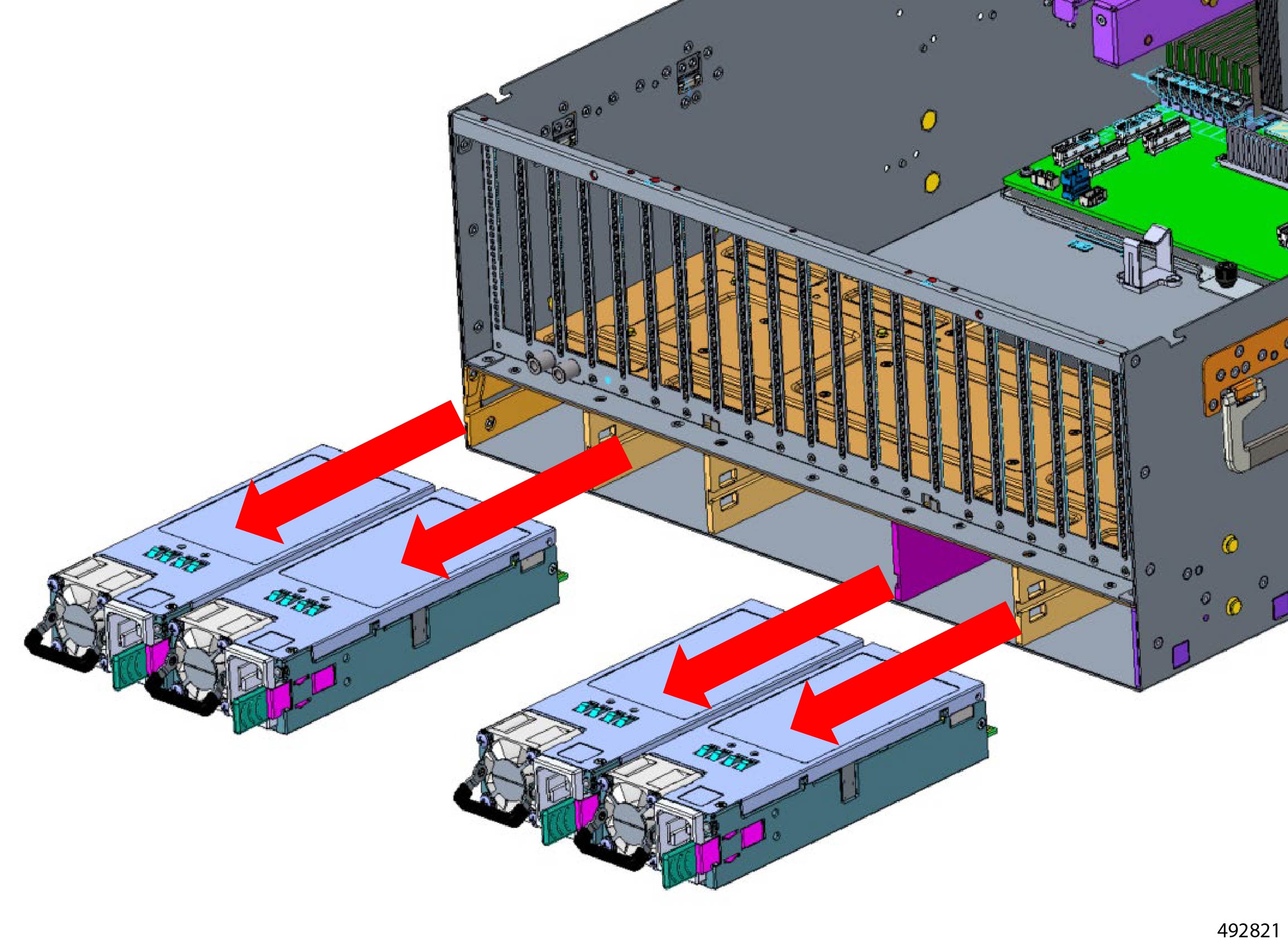
Step 20
|
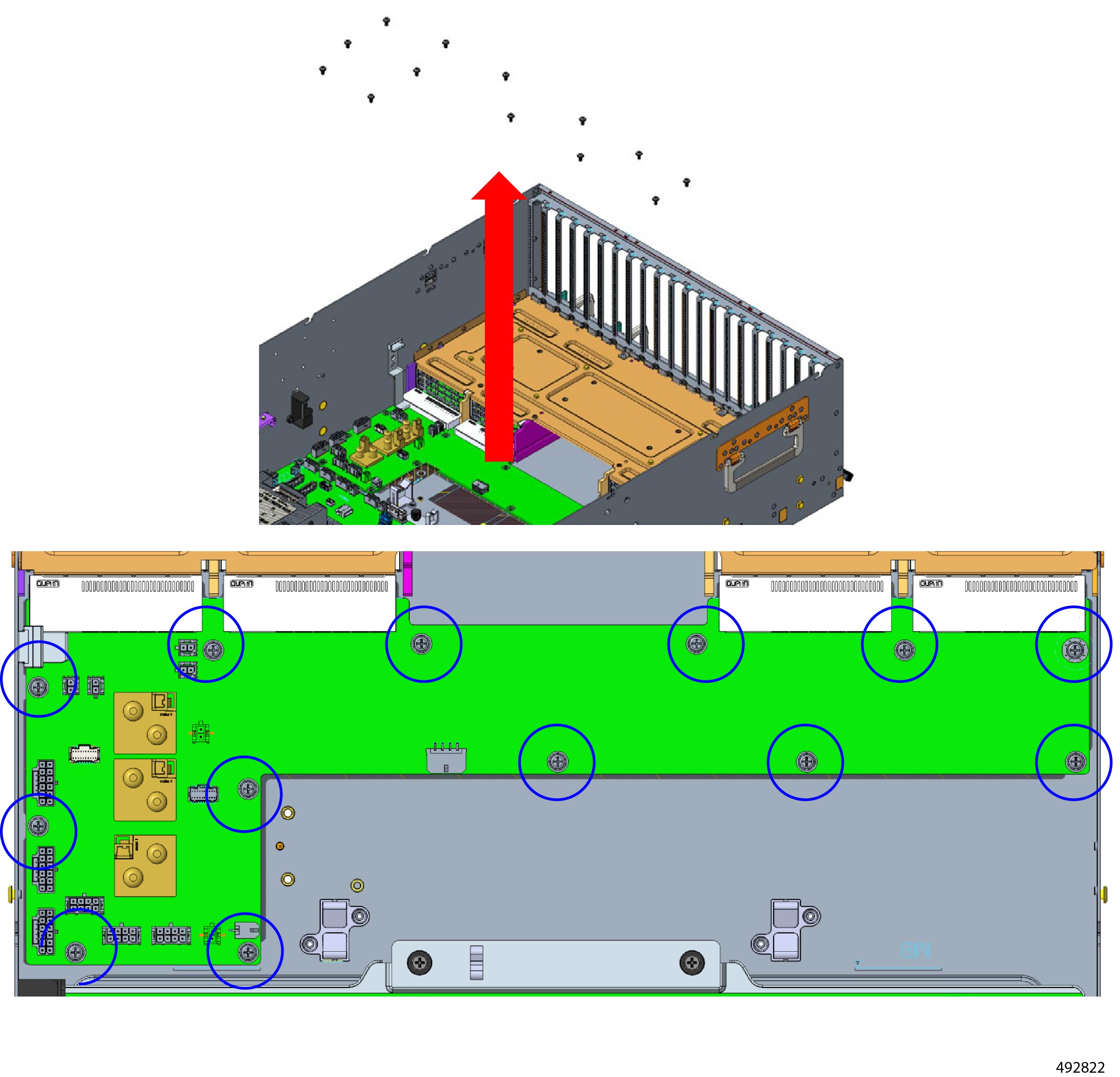
Remove the PDB Board.
-
Remove the PSUs to access the board.
-
Locate and remove the PDB board screws.
-
Disconnect the PDB Board.
|
|
Step 21
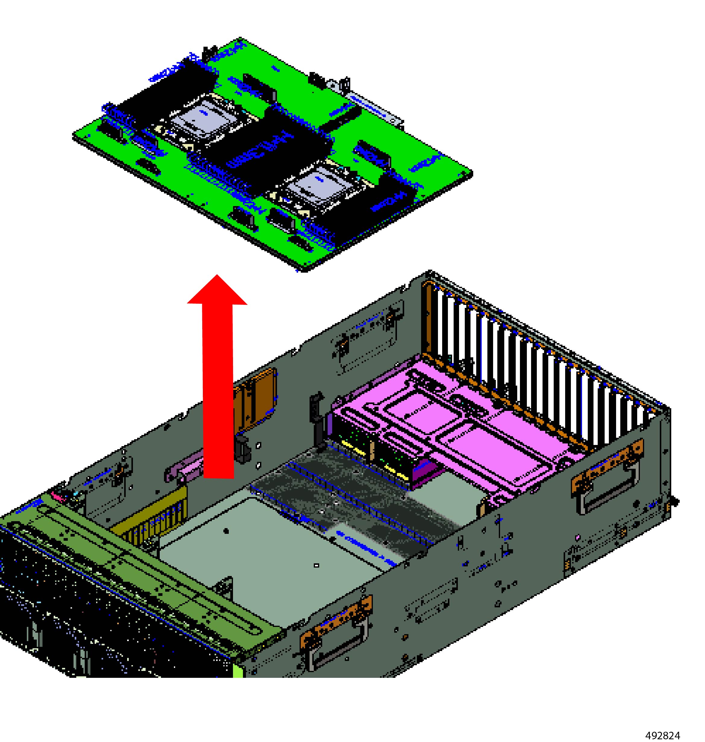
|
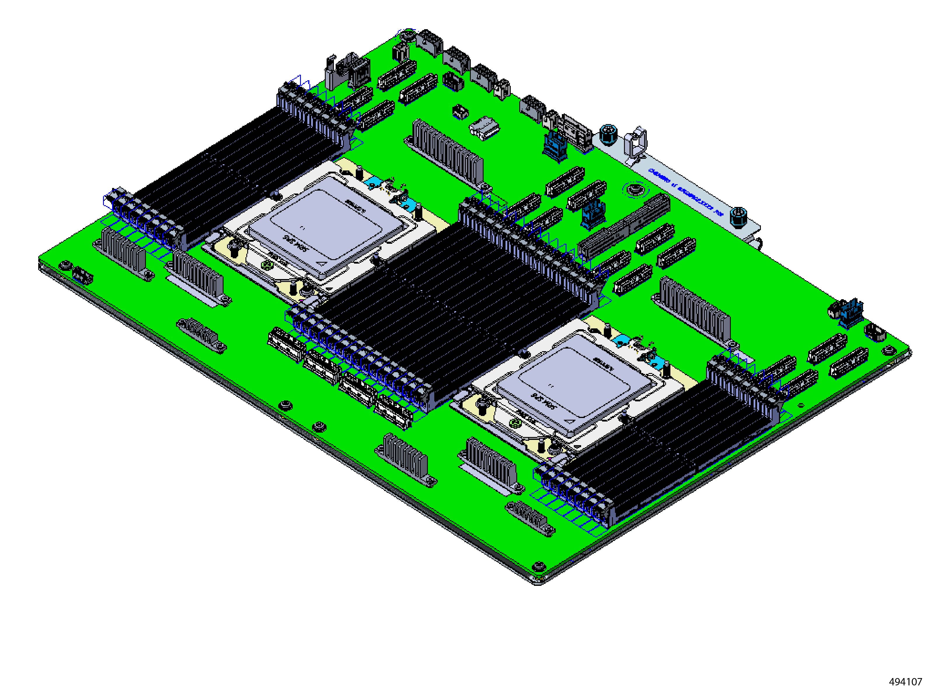
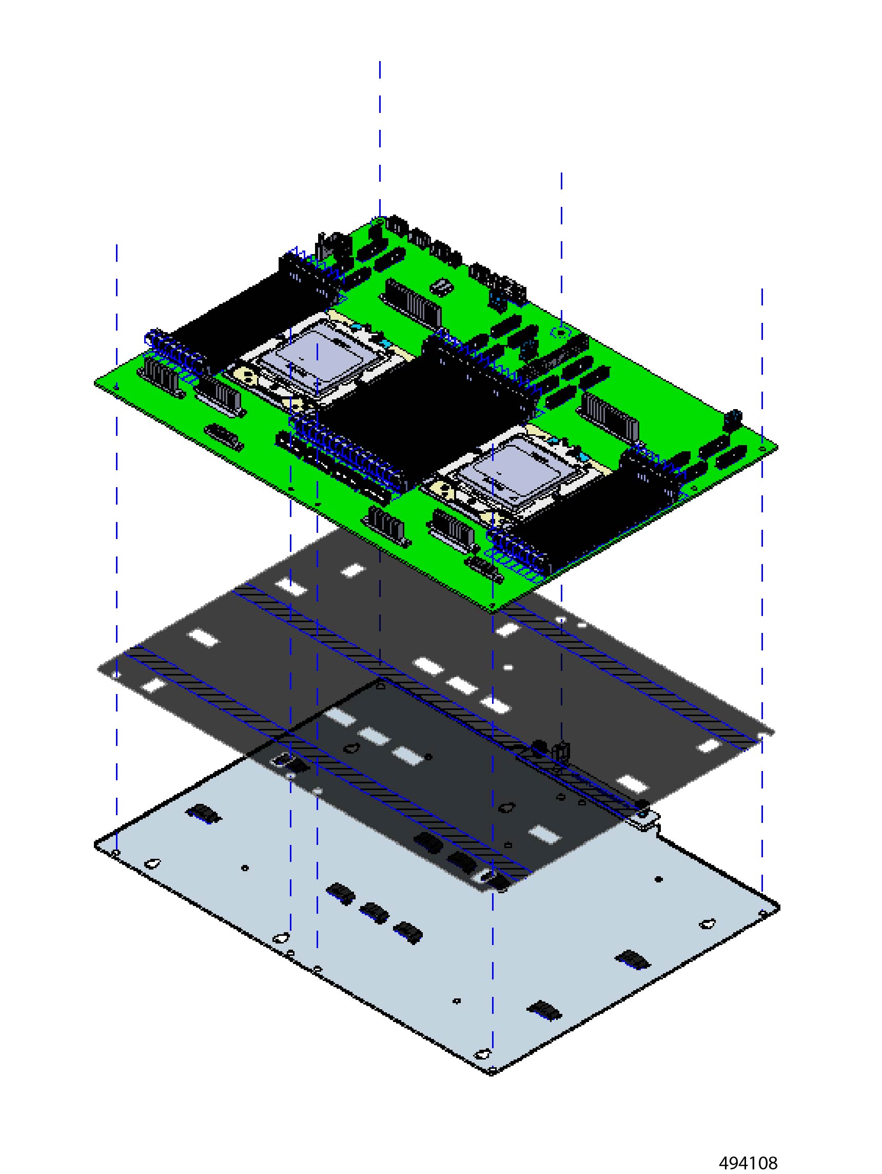
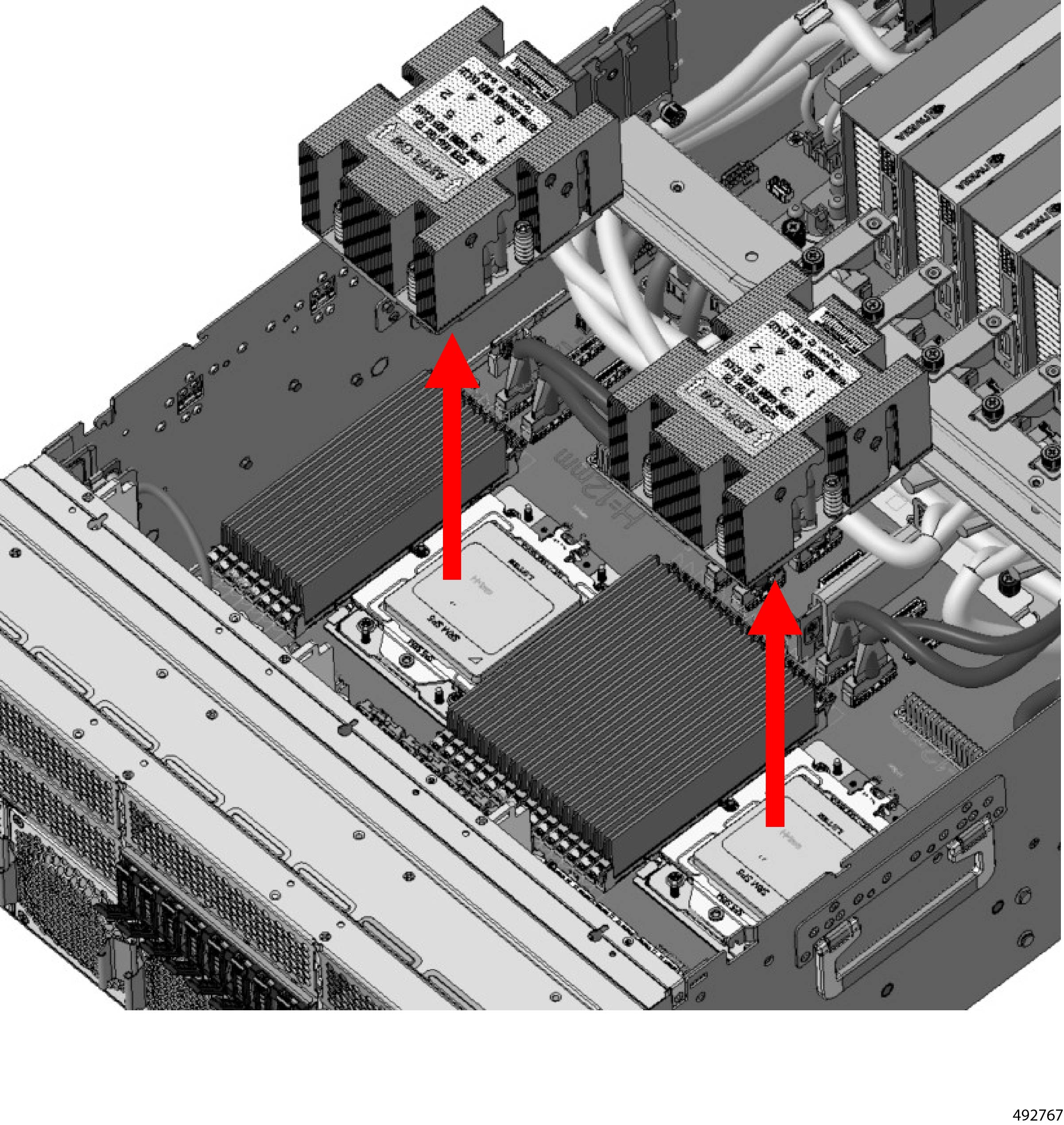
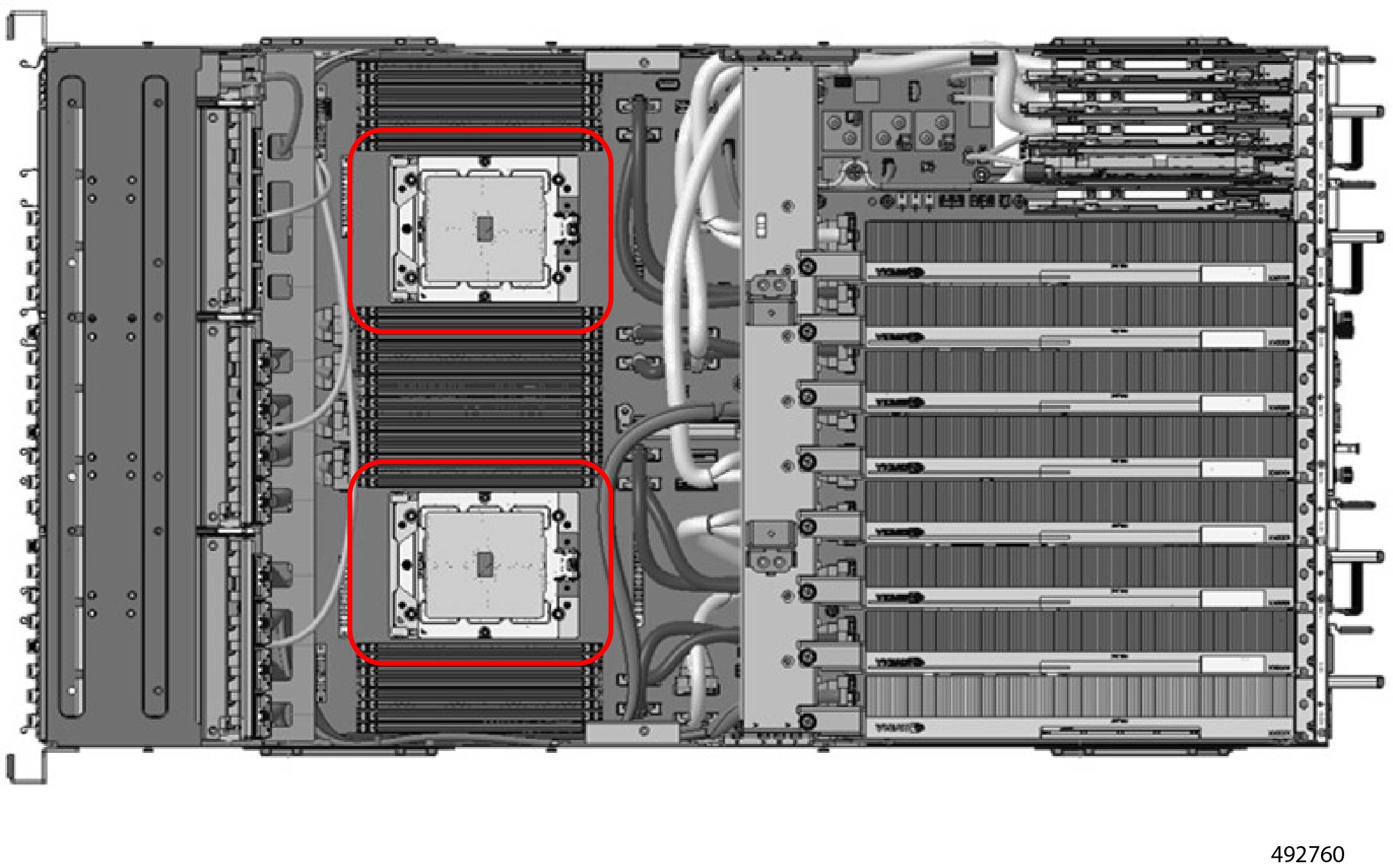
Remove main CPU board.
-
Locate and remove the screws.
-
Disconnect and remove the main CPU board.
|
|
Step 22
|
If needed, you can continue by Recycling the Chassis Motherboard.
|


 Feedback