Installing the Server

This chapter contains the following topics:

Install Warnings and Guidelines


Note


Before you install, operate, or service a server, review the Regulatory Compliance and Safety Information for Cisco UCS C-Series Servers for important safety information.


Warning


The fully configured server weighs approximately 265 lbs. (120 kg)! Never attempt to lift the server by yourself! Instead, use a lift, scissors jack, or some other device to lift and bear the weight of the server while you are installing or servicing it. If you must lift or handle the server without mechanical assistance, use two or more people to lift and handle server. Always use safe lifting practices when lifting or moving the server.


Caution


When connecting the chassis to facility power, make sure not to overload the capacity of a PDU or power strip. For example, do not connect all PSUs to one PDU or power strip that is not capable of carrying the total power draw of the chassis.


Caution


To ensure proper airflow it is necessary to rack the servers using rail kits. Physically placing the units on top of one another or “stacking” without the use of the rail kits blocks the air vents on top of the servers, which could result in overheating, higher fan speeds, and higher power consumption. We recommend that you mount your servers on rail kits when you are installing them into the rack because these rails provide the minimal spacing required between the servers. No additional spacing between the servers is required when you mount the units using rail kits.


Caution


Avoid uninterruptible power supply (UPS) types that use ferroresonant technology. These UPS types can become unstable with systems such as the Cisco UCS, which can have substantial current draw fluctuations from fluctuating data traffic patterns.


When you are installing a server, use the following guidelines:

  • Plan your site configuration and prepare the site before installing the server. See the Cisco UCS Site Preparation Guide for the recommended site planning tasks.

  • Ensure that there is adequate space around the server to allow for accessing the server and for adequate airflow. The airflow in this server is from front to back.

  • Ensure that the air-conditioning meets the thermal requirements listed in the Environmental Specifications. .

  • Ensure that the site power meets the power requirements listed in the Power Specifications.. If available, you can use an uninterruptible power supply (UPS) to protect against power failures.

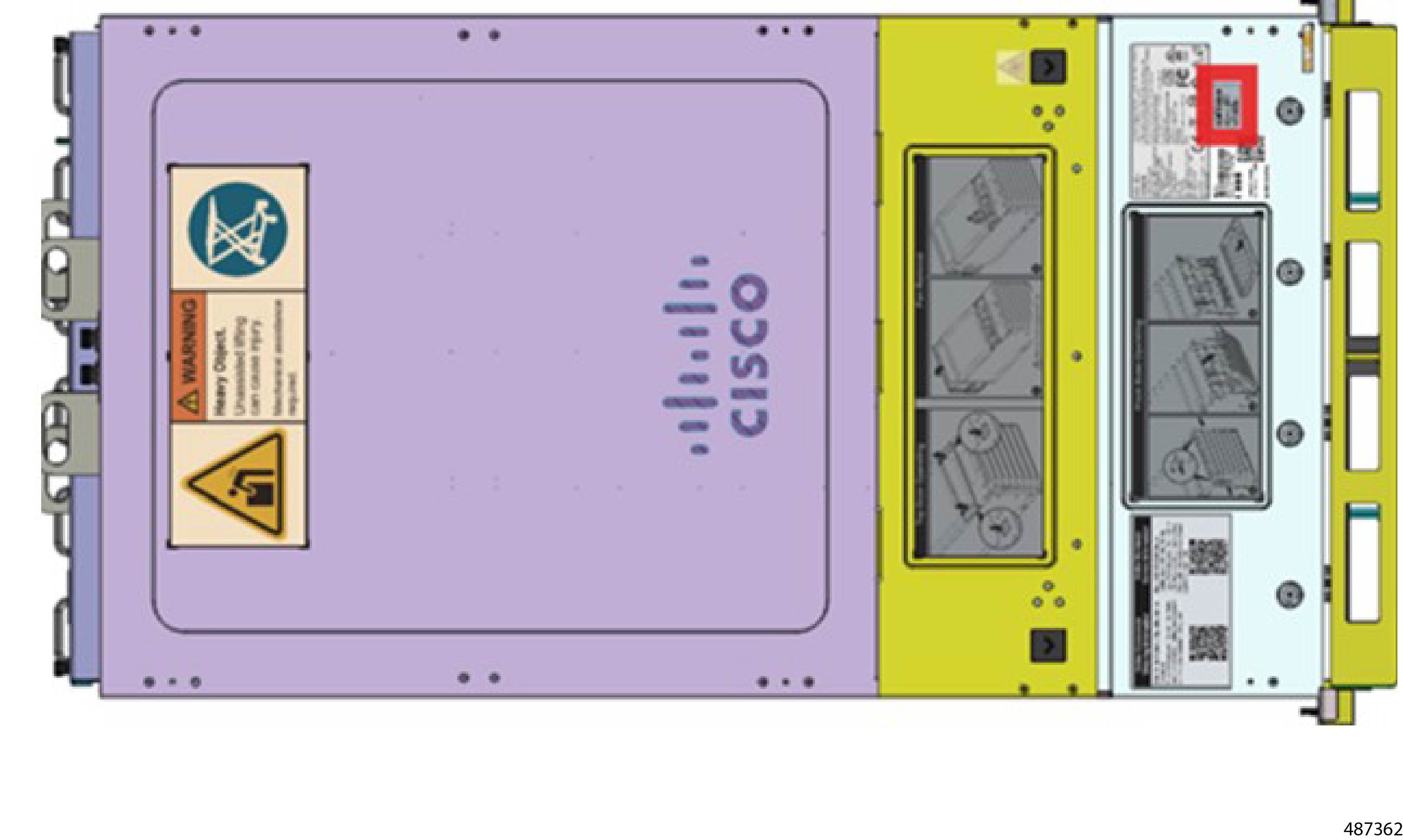
  • Before attempting rack installation of the server, you will find it helpful to note important information, such as the server's MAC address and serial number, off of the label at the top right corner of the server.
    Figure 1. Location of MAC Address Label
Statement 1005—Circuit Breaker


Warning


This product relies on the building’s installation for short-circuit (overcurrent) protection. To reduce risk of electric shock or fire, ensure that the protective device is rated not greater than: 240V, 16 A.


Rack Requirements

Rack Specification

The rack must be of the following type:

  • Rack Type: A standard 19-inch (48.3 cm) wide, four-post EIA rack.

  • Mounting Posts: Must conform to universal hole spacing as per ANSI/EIA-310-D-1992.

  • Rack-Post Holes:

    • Square: 9.5 mm

    • Round: 7.1 mm

  • Vertical Rack Space: Minimum vertical rack space per server is 2 rack units (2U), equal to 3.5 inches (88.9 mm).

Slide Rail Specifications

  • Slide Type: L-shelf

  • Install Type: Toolless

  • Slide Length: 645 mm

  • Working Load: 150 kg

  • Supported Rack Range: 645~917 mm

  • Supported Chassis Width: 448 mm

  • Use Space: 2U*645 mm

  • UL Strength Test: Yes

Cisco Slide Rail Kit, which is shipped with the server or with a replacement chassis.

Tools Required for Rack Installation

Following tools are required:

  • #2 Phillips Screwdriver

  • Lift table. If a lift table is not available, make sure to use at least two people to lift or maneuver the server.

Installing the Server

Before you begin

  • Ensure the floor where the rack is placed can support the combined weight of the rack, server, and any other equipment.

  • Have a team of at least two to three people to assist with lifting and positioning the server.

  • Clear the area around the rack to ensure there is enough space to work.

  • Inspect the rack and server for any damage before starting the installation.

  • Consult Install Warnings and Guidelines.

Procedure


Step 1

Locate the Left Front and Right Front rails.

Step 2

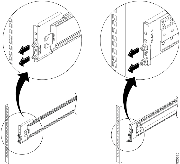
Install rear right and left rails:

  1. Align the guide pins of left/right side rail with rack holes in rack rear side and push the rail to lock on rack.

  2. Push the rail until it hooks into position.

  3. Check whether the rail hook position is hooked.

    Figure 2. Rear Right/Left Rail -Front side

Step 3

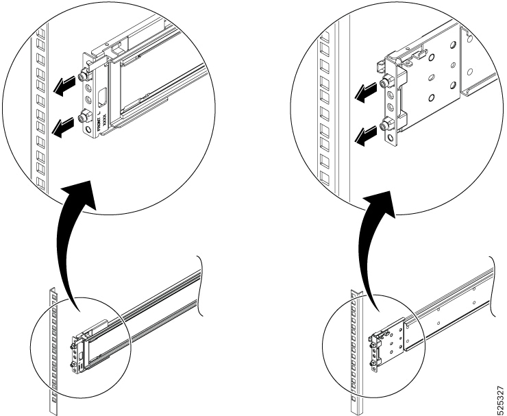
Install front right and left rails:

  1. Align the guide pins of Left/Right side rail with rack holes in rack front side and push the rail to lock on rack.

  2. Push the rail until it hooks into position.

  3. Check whether the rail hook position is hooked.

    Figure 3. Front Right Rail
  4. Align the guide pins of the left rail with the rack holes on the front left side.

  5. Align the guide pins of the right rail with the rack holes on the front right side.

  6. Push the rail until it hooks into position.

  7. Check whether the rail hook position is hooked.

Step 4

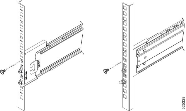
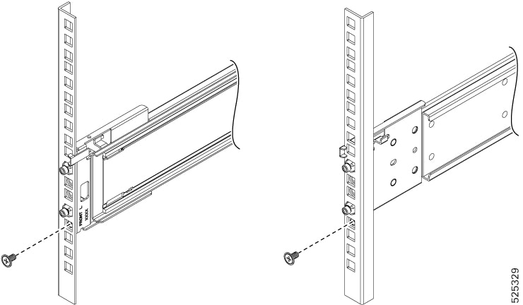
Secure the Rails:

  1. Rear Left and Rear Right: Ensure the rails are aligned and locked by screws.

    Figure 4. Rear Left / Rear Right
  2. Front Left and Front Right: Ensure the rails are aligned and locked by screws.

    Figure 5. Front Left /Front Right

Step 5

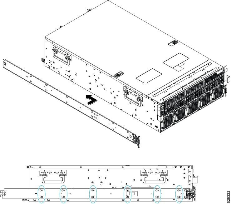
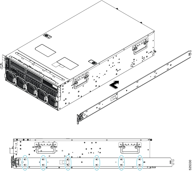
Install left and right side rail mounts.

  1. Install left side slide rail on system by 12*T-pins

    Figure 6. Left -side Rail Mount Installation
  2. Install right side slide rail on system by 12*T-pins

Figure 7. Right side rail mount

Step 6

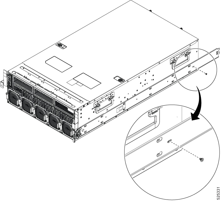
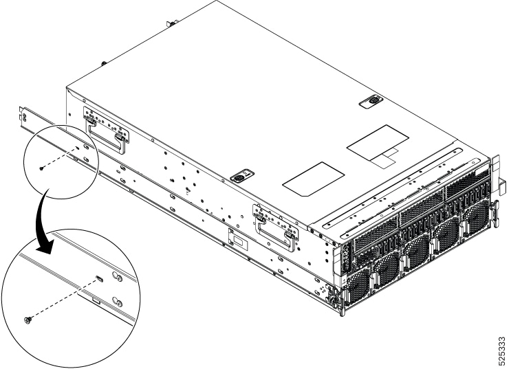
Attach the right side and left side rails to the server using the ## screws

Figure 8. Attach right side rail mount
Figure 9. Attach left side rail mount

Step 7

After you install the the rail mounts, use a mechanical lift or scissors jack (not included) align the server at the correct height in the rack.

If a server lift is not available, you will need at least two people to lift the chassis into place.

Warning


The fully configured server weighs approximately 265 lbs. (120 kg)! Never attempt to lift the server by yourself! Instead, use a lift, scissors jack, or some other device to lift and bear the weight of the server while you are installing or servicing it. If you must lift or handle the server without mechanical assistance, use two or more people to lift and handle server. Always use safe lifting practices when lifting or moving the server.

Step 8

Carefully slide the server into the rack, ensuring it aligns with the rails and position the server correctly within the rack.

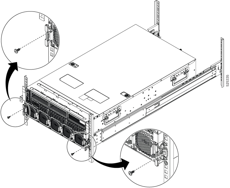
Step 9

Ensure that the server is securely fastened with the two lock screws on the left and right sides. Use a #2 screwdriver to tighten the screws.

Figure 10. Tightening Screws

Step 10

When the server is installed in the rack and all trays are in place, connect the PSUs to facility power.

The server will power up when the facility power circuit is energized. As part of the server boot up sequence, a power on self-test (POST) occurs. If an error is encountered, a POST error code is displayed, if available. For more information, go to FPGA Power Sequence and Error Codes.


Initial Server setup

After rack installation and power on, the server can be assigned an IP address and connected to server management through the Cisco BMC to enable the server to operate in standalone mode.

Connection Methods

There are two methods for connecting to the system for initial setup:

  • Local setup—Use this procedure if you want to connect a keyboard and monitor directly to the system for setup. This procedure requires a Mini-DVI to VGA adapter connecting to the rear of the server.

  • Remote setup—Use this procedure if you want to perform setup through your dedicated management LAN.


Note


To configure the system remotely, you must have a DHCP server on the same network as the system. Your DHCP server must be preconfigured with the range of MAC addresses for this server node.


The server's MAC address is printed on a label that is on the top right corner of the server. The MAC address printed on the label is the beginning of the range of six contiguous MAC addresses.

Use the following topics to connect to the server.

Connecting to the Server Locally For Setup

This procedure requires the following equipment:

  • VGA monitor

  • USB keyboard

  • A cable connects between the Mini Display Port and the monitor

Procedure


Step 1

Connect a USB keyboard and a monitor to the server using a Mini Display Port cable.

Step 2

Attach a power cord to each power supply in your server, and then attach each power cord to a grounded AC power outlet.

Wait a few minutes to let the server boot to standby power during the first bootup. The Seven-Segment LEDs should read “FF_03”. You can verify system power status by looking at the system Power Status LED on the front panel. The system is in standby power mode when the LED is blinking green.

The following table shows the LED blink codes.

Status

Status Description

Off

Power is off.

Green, fast blink

Pre-S5

Green, slow blink

S5

Green, solid

S0

Amber, solid

Warning

Step 3

Configure the Cisco BMC Settings.

  1. Press the front panel power button to boot the server.

  2. During bootup, press DEL or ESC when prompted to open the BIOS Setup Menu. Use the arrow key to navigate to the Server Mgmt page.

  3. Using the arrow keys, move down to BMC Network Configuration

Step 4

Continue with Configuring Cisco BMC Network Settings.


Connecting to the Server Remotely For Setup

This procedure requires the following equipment:

  • One RJ-45 Ethernet cable that is connected to your management LAN.

Before you begin


Note


To configure the system remotely, you must have a DHCP server on the same network as the system. Your DHCP server must be preconfigured with the range of MAC addresses for this server node. The MAC address is printed on a label that is on the top right corner of the server. See Install Warnings and Guidelines.

Procedure


Step 1

Plug your management Ethernet cable into the dedicated management port on the rear panel.

Step 2

Attach a power cord to each power supply in your server, and then attach each power cord to a grounded AC power outlet.

Wait a few minutes to let the server boot to standby power during the first bootup. The Seven-Segment LEDs should read “FF_03”. You can verify system power status by looking at the system Power Status LED on the front panel. The system is in standby power mode when the LED is blinking green.

The following table shows the LED blink codes.

Status

Status Description

Off

Power is off.

Green, fast blink

Pre-S5

Green, slow blink

S5

Green, solid

S0

Amber, solid

Warning

Step 3

Allow your preconfigured DHCP server to assign an IP address to the server node.

Step 4

Use the assigned IP address to access and log in to the Cisco IMC for the server node. Consult with your DHCP server administrator to determine the IP address.

Note

 
The default user name for the server is root. The default password is password.

Step 5

From the KVM page under Operations, click Launch KVM. A separate KVM console window opens.

Step 6

From the Server power operations page under Operations, click Power On. The system powers on.

Step 7

Select the KVM console window.

Note

 
The KVM console window must be the active window for the following keyboard actions to work.

Step 8

When prompted, press Del or Esc to enter the BIOS Setup Menu.

Note


The first time that you enter the Cisco IMC Configuration Utility, you are prompted to change the default password. The default password is password where the initial password character is zero. The Strong Password feature is enabled.

The following are the requirements for Strong Password:

  • The password can have a minimum of 8 characters and a maximum of 14 characters.

  • The password must not contain the user’s name.

  • The password must contain characters from three of the following four categories:

    • English uppercase letters (A through Z)

    • English lowercase letters (a through z)

    • Base 10 digits (0 through 9)

    • Non-alphabetic characters !, @, #, $, %, ^, &, *, -, _, =, “

Step 9

Continue with Configuring Cisco BMC Network Settings.


Configuring Cisco BMC Network Settings

This task configures the Cisco baseboard management controller (BMC) to enable server boot up.

Before you begin

Perform this procedure after you connected to the system and opened the Server Mgmt menu.

Procedure


Step 1

Choose whether to enable DHCP (default) for dynamic network settings, or to enter static network settings.

The static IPv4 settings include the following:
  • The Cisco IMC IP address.

  • The subnet mask.

  • The gateway/router IP address.

Step 2

(Optional) Configure VLAN settings as needed for your network.

Step 3

Press F4 to save your settings and reboot the server.

Note


The assigned IP will be displayed on the console screen during bootup.

Step 4

Continue with Cisco IMC management Interface.


Connecting to the Cisco Baseboard Management Controller Interface

To manage the server, see the Cisco UCS C-Series Integrated Management Controller GUI Configuration Guide or the Cisco UCS C-Series Servers Integrated Management Controller CLI Configuration Guide for instructions about using those interfaces for Cisco Baseboard Management Controller 2.0. The links to the configuration guides are in the Cisco Baseboard Mangaement Controller 2.0.

Use the following procedure to connect to the Cisco Baseboard Management Controller interface.

Before you begin

If you have not already configured the Cisco BMC settings, do so now. Go to Configuring Cisco BMC Network Settings.


Note


The factory default username for the server is root. The default password is password.


Procedure


Step 1

Open a browser.

Step 2

In the browser's address field, enter the IP address of the Cisco Baseboard Management Controller to connect to its management interface.

The IP address is based on the settings that you made (either a static address or the address assigned by your DHCP server).

Note


The first time that you enter the Cisco Baseboard Management Controller's management interface, you are prompted to change the default password. The default password is password, where the initial password character is zero.

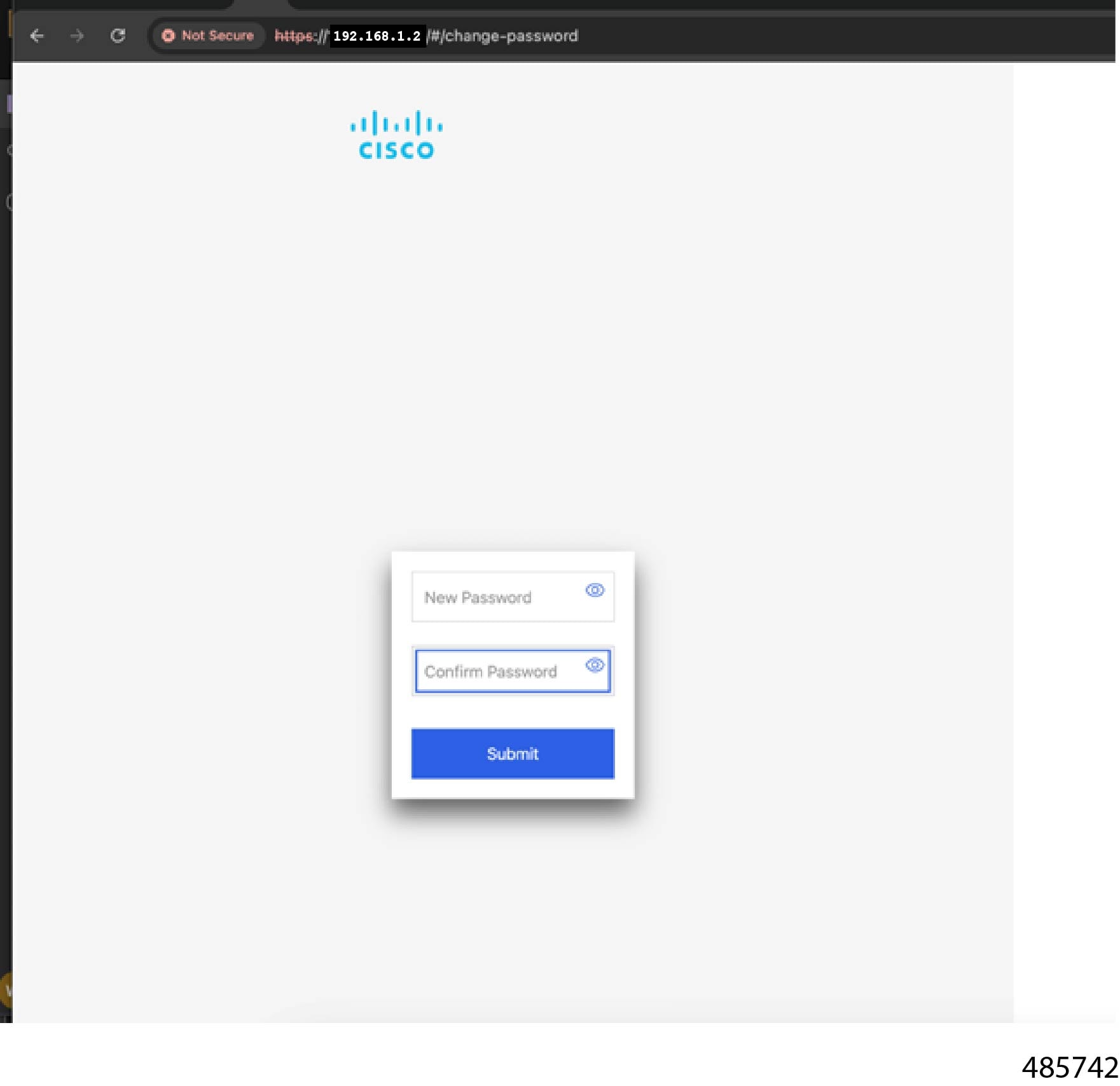
Step 3

If this is the first time you have entered the Cisco Baseboard Management Controller's management interface, you must configure a strong password.

Follow these guidelines for a strong password:

  • The password can have minimum 8 characters; maximum 20 characters.

  • The password must not contain the user’s name.

  • The password must not be a palindrome, which is a word that is spelled the same forwards and backwards.

  • You can use consecutive or repeated characters, but they cannot exceed half the total number of characters in the password.

Step 4

Click Submit.


Server Configuration Management

The Cisco UCS C845A M8 rack server can be configured and managed using the following Cisco BMC management and configuration tool, which enables such tasks as:

  • Launching a KVM Launch and KVM Session management.

  • System Inventory

  • Power operations

  • User management and certificates

  • System firmware management

  • Boot order configuration

  • Monitoring

  • Event logs