FlashStack with Nutanix Cloud Infrastructure Software Deployment Guide
Available Languages
Bias-Free Language
The documentation set for this product strives to use bias-free language. For the purposes of this documentation set, bias-free is defined as language that does not imply discrimination based on age, disability, gender, racial identity, ethnic identity, sexual orientation, socioeconomic status, and intersectionality. Exceptions may be present in the documentation due to language that is hardcoded in the user interfaces of the product software, language used based on RFP documentation, or language that is used by a referenced third-party product. Learn more about how Cisco is using Inclusive Language.
- US/Canada 800-553-2447
- Worldwide Support Phone Numbers
- All Tools
 Feedback
 Feedback

In partnership with:

About the Cisco Validated Design Program
The Cisco Validated Design (CVD) program consists of systems and solutions designed, tested, and documented to facilitate faster, more reliable, and more predictable customer deployments. For more information, go to: http://www.cisco.com/go/designzone
Executive Summary
Business demands are rapidly outpacing the limitations of existing infrastructure choices. Organizations are seeking infrastructure solutions that are simplified, flexible, independently scalable, powerful, and agile solutions that avoid locking them into a specific software suite and enable them to repurpose existing hardware investments. In addition, with recent rapid changes in virtualization, many customers are reevaluating their current virtualization strategies and looking for new paths forward.
FlashStack, originally developed by Cisco and Pure Storage, offers a pre-engineered Converged Infrastructure solution that integrates compute, storage, and networking, reducing IT risk by validating the architecture and ensuring compatibility across all components. FlashStack’s success is rooted in its adaptability and ongoing evolution, consistently incorporating the latest technology and product innovations in management, compute, storage, and networking.
To address the evolving needs, Nutanix joined the decade-long partnership of Cisco and Pure Storage to bring the Nutanix hypervisor (AHV) support to FlashStack. By combining industry-leading Cisco UCS compute, Pure Storage, and the Nutanix Cloud Platform, this solution offers a robust virtualization platform purpose built to address modern customer challenges. The architecture is ideally suited for hosting enterprise-critical workloads that demand consistent performance, support for mixed workloads with varying I/O requirements, large virtual machine farms, and independent scalability of compute and storage resources.
This document presents validated best practices design and deployment details for FlashStack with Nutanix AOS and AHV, built with Cisco UCS, Cisco Networking, and Pure Storage FlashArray. It explains two deployment types; Greenfield deployment for customers with no existing Cisco UCS or Pure Storage infrastructure and brownfield deployment for customers who have already invested in Cisco UCS or Pure Storage and wish to repurpose their existing hardware investments.
Solution Overview
This chapter contains the following:
● Audience
FlashStack with Nutanix Cloud Platform represents a cohesive and flexible validated converged infrastructure solution that combines compute, network, and storage resources into a single, integrated architecture. Designed as a collaborative effort between Cisco, Pure Storage, and Nutanix, this converged infrastructure platform is engineered to deliver high levels of efficiency, scalability, and performance, suitable for a multitude of data center workloads. By standardizing on a validated design, organizations can accelerate deployment, reduce operational complexities, and confidently scale their IT operations to meet evolving business demands.
The FlashStack architecture leverages Cisco's Unified Computing System (Cisco UCS) servers, Cisco Nexus networking, Pure’s innovative storage systems, and Nutanix Cloud Platform (NCP) software, providing a robust foundation for virtualized environments.
The intended audience for this document includes, but is not limited to IT architects, sales engineers, field consultants, professional services, Cloud Native teams, IT managers, IT engineers, partners, and customers who are interested in taking advantage of an infrastructure built to deliver IT efficiency and enable IT innovation.
This document provides deployment guidance for setting up the FlashStack solution with NCP. This document introduces various design elements and explains various considerations and best practices for a successful Nutanix Compute Cluster using Cisco UCS and Pure Storage FlashArray.
Some of the highlights of FlashStack with Nutanix are:
● Alternate and Flexible Virtualization Infrastructure: FlashStack with Nutanix offers an alternative full-stack virtual infrastructure that is modern, scalable, and ready to handle most mission-critical, data-intensive workloads. This integrated solution combines the operational simplicity of Nutanix Cloud Infrastructure (NCI) solution with the high-performance and modular FlashStack architecture, delivering improved and consistent application performance. This solution stands out as the standard virtualization infrastructure choice for customers who are looking to re-evaluate and modernize their virtualization strategies.
● Repurpose the existing infrastructure Investments: This solution enhances the value of existing Cisco UCS servers and Pure Storage FlashArrays. By leveraging the stateless computing architecture of Cisco UCS alongside the modular design of Pure Storage FlashArrays, organizations can repurpose previous-generation hardware and maximize their infrastructure investments. This approach enables seamless modernization without the need to replace current assets, allowing organizations to upgrade and innovate while fully utilizing their existing technology resources.
● Seamless Solution Integration: All the components of the solution are deeply integrated to enable seamless Nutanix cluster provisioning, cluster expansion and lifecycle management of the entire solution. Cisco Intersight Device Connector for Nutanix Prism Central, combined with Pure Storage FlashArray integration, delivers a unified view of the entire solution through a single management console.
● Scalability and Consistent performance: HyperConverged Infrastructure (HCI) offers linear and predictable scaling, which is great for some workloads, however, some customers need more flexibility with independent hardware resource scalability. The modular architecture of FlashStack enables independent scaling of compute and storage resources, allowing organizations to meet the ongoing business demands of modern IT applications. Cisco UCS’s modular and stateless computing combined with Pure Storage FlashArray’s modular NVMe architecture delivers a high-performance solution that is ideally suited for mission-critical workloads with varying I/O requirements. In addition, this architecture utilizes NVMe over Fabric (NVMe-oF) protocol over TCP (NVMe/TCP) extending the high-performance benefits of NVMe architecture of FlashArray across standard Ethernet networking using TCP/IP.
● Operational efficiency and Consistent infrastructure configuration: The solution provides unified management through Cisco Intersight, Prism Central, and Pure1. This integrated approach enables centralized monitoring, management, and automation across compute, storage, and virtualization layers, simplifying operations and enhancing visibility for IT administrators. Intersight Integration with Nutanix Foundation Central (FC) automates and enhances deployment experience without hopping on to multiple management points avoiding human configuration errors. In addition to the compute-specific hardware and software innovations, integration of the Cisco Intersight cloud platform with Pure Storage FlashArray and Cisco Nexus delivers monitoring, orchestration, and workload optimization capabilities for different layers of the FlashStack solution.
Technology Overview
This chapter contains the following:
● FlashStack with Nutanix Cloud Platform
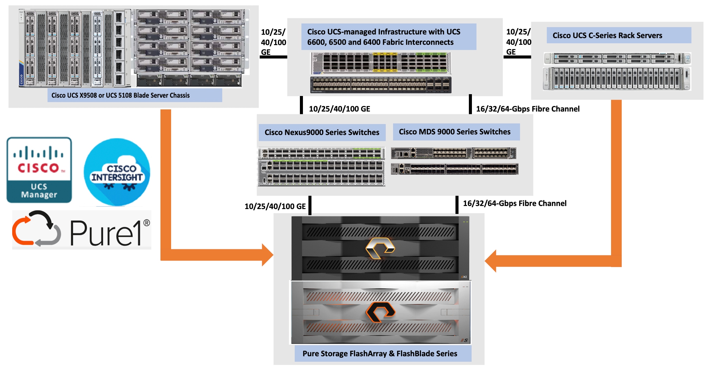
All FlashStack components are integrated, allowing you to deploy the solution quickly and economically while eliminating many of the risks associated with researching, designing, building, and deploying similar solutions from the foundation. One of the main benefits of FlashStack is its ability to maintain consistency at scale. Figure 1 illustrates the series of hardware components used for building the generic FlashStack architectures. Each of the component families; Cisco Unified Computing System (Cisco UCS), Cisco Nexus, Cisco MDS, and Pure Storage FlashArray systems, offers platform and resource options to scale-up or scale-out the infrastructure while supporting the same features and functions. For more details on the FlashStack architecture, go to: FlashStack.
FlashStack with Nutanix Cloud Platform
Nutanix Cloud Platform (NCP) is a comprehensive hybrid cloud infrastructure solution. The NCP combines the core elements of its HCI technology with additional cloud services, automation, and integrations, enabling organizations to build, manage, and optimize their IT infrastructure across on-premises, edge, and public cloud environments. The high-level design of the solution is described in Figure 2.
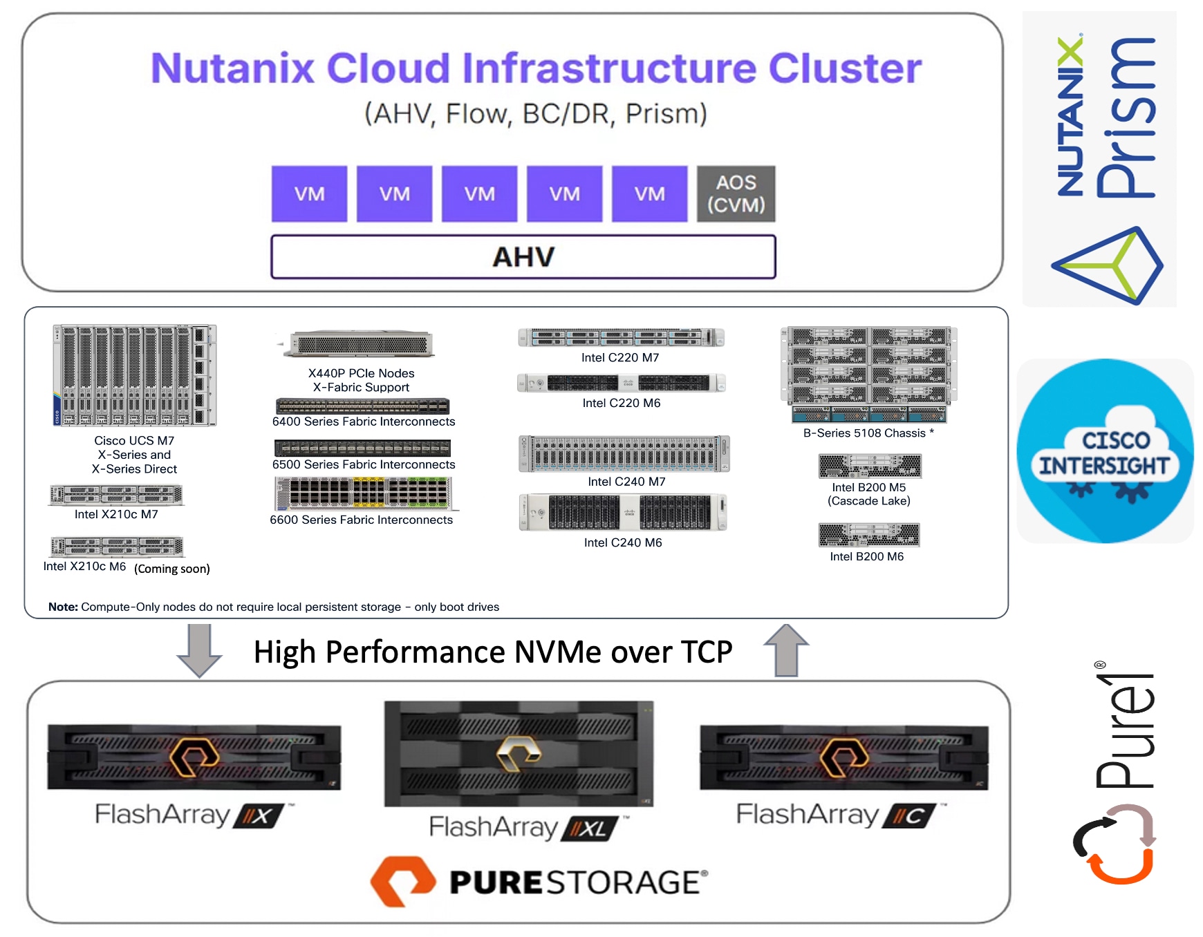
Nutanix Cloud Infrastructure (NCI) is the core software stack of NCP that unifies compute, storage, and networking into a single, scalable software-defined system simplifying management across data centers, edge and public-clouds for hybrid multi-cloud environments. It offers simplified operations leveraging AHV for virtualization and AOS for storage and data services and Prism Central for centralized management across the environments.
Nutanix Acropolis Hypervisor (AHV) is a native, enterprise-grade virtualization solution built directly into the Nutanix Cloud Infrastructure, eliminating the complexity and cost of third-party virtualization while delivering enterprise-grade performance and scalability. High availability of VMs, Live Migration, Dynamic scheduling, Integrated Networking are the core features of AHV. Nutanix Flow adds policy-driven micro segmentation and virtual networking, providing granular control over east-west traffic and helping meet compliance requirements. Designed around virtual machines, it enables fast provisioning, easy scaling, responsive performance, and built-in resilience for business-critical applications.
Nutanix Cloud Infrastructure – Compute Cluster is part of the NCP and provides core compute capabilities, while storage is facilitated by the external storage array. The NCI Compute Cluster runs Nutanix AHV and AOS software on a set of Compute-Only (CO) nodes like Cisco UCS x86 standard servers and forms a compute cluster backed by an external Pure Storage FlashArray. The NCI compute cluster provides compute resources to the VMs, delivers VM availability, security, disaster recovery, and lifecycle management functionalities. The cluster does not include any directly attached storage; instead, it consumes storage from an externally connected Pure Storage FlashArray through the Nutanix AOS storage controller.
The role of Nutanix Acropolis Operating System (AOS) in this NCI Compute cluster architecture is different from its traditional HCI architectures. All the code changes required for enabling and integrating external storage into the solution are done within the AOS controller VM, not at the AHV hypervisor level. Some of the key responsibilities of AOS controller VM are:
● External Storage Array connectivity: The AOS controller VM acts as a translator, connecting the AHV hypervisor to the external storage via NVMe-over-Fabric (NVMe-oF) over TCP. NVMe-oF over TCP is a protocol that enables NVMe storage devices to connect and communicate across standard Ethernet network using TCP/IP. This approach delivers the high-speed and low-latency benefits of NVMe storage without requiring specialized hardware, making it simple, scalable and cost effective high performance storage solution. The increase in Ethernet speeds (25/40/100 GbE and beyond) significantly accelerates adoption of NVMe-oF over TCP.
● Data Path Redundancy: AOS ensures if a network path to the storage fails, the VM’s storage access is automatically rerouted (autopathing).
● Snapshot and Clones: AOS delegates these operations to the external storage but presents them to the administrator as standard Nutanix VM-Level operations.
● DR Automation: AOS manages disaster recovery orchestration and replication for VMs even though the actual data blocks reside on the external storage array.
● Unified Operations via Prism: Even without local storage to manage, AOS enables you to manage VMs, networking, and security policies from the same standard Prism interface used for standard HCI clusters.
Cisco UCS is an integrated data center platform that combines compute, networking, and storage into a single, centrally managed system, simplifying management, reducing complexity, and improving efficiency for diverse workloads like virtualization, cloud, and AI. Key components include servers (blades, rack, modular) and Fabric Interconnects (FIs) for unified connectivity.
FlashStack with Nutanix Integrates Cisco UCS servers (Cisco UCS C-Series, Cisco UCS B-Series, and Cisco UCS X-Series) as compute-only nodes with Nutanix’s Cloud Platform and external Pure Storage FlashArray, creating a flexible, disaggregated infrastructure managed by Cisco Intersight.
● The stateless computing model (where every compute aspect is virtualized and abstracted) and midplane-free modular design of Cisco UCS set it apart as a unique server platform. This approach enables you to repurpose their existing servers by converting them into fully supported Nutanix nodes, maximizing investment and flexibility.
● Currently, the last two generation server platforms for blades and racks: Cisco UCS B200 M5, Cisco UCS B200 M6, Cisco UCS C220 M6, Cisco UCS C240 M6, and Cisco UCS X210c M7, Cisco UCS X210c M6, Cisco UCS C220 M7, and Cisco UCS C240 M7 are supported by the solution. Support for Cisco UCS M8 server platforms will be available in the future releases of the solution.
● The CO nodes do not require local disks for persistent storage. Only Local M.2 SSD disks are used for booting the AHV hypervisor and storing the AOS Controller VM binaries on the Nutanix node. The CO nodes connect to the Pure Storage FlashArray for virtual machine storage utilizing the NVMe over Fabrics (NVMe-oF) protocol over TCP.
● NVMe over TCP provides a highly simplified and fast way to access storage across IP networks, delivering high performance and low latency without requiring specialized network infrastructure. As Ethernet network speeds continue to increase, the adoption of NVMe over TCP is further accelerated, enabling even faster data transfer and improved performance for storage solutions over standard IP networks.
Pure Storage FlashArray provides storage services such as user data persistence, data resiliency, data availability, data security, and data efficiency.
● The Pure Storage Platform delivers a unified, cloud-like storage-as-a-service foundation that consolidates block, file, and object with simple, centralized management, cutting complexity and accelerating outcomes.
● FlashArray//X, //XL and //C series arrays are supported and support other series arrays will be available in the future phases of the program. Built on Evergreen architecture for non‑disruptive upgrades (even with in-place upgrades) and zero‑downtime operations, it future-proofs the estate while driving cost, space, and energy efficiency so teams can focus on innovation instead of migrations.
● It’s always-on global compression and deduplication deliver industry-leading data efficiency, often requiring significantly less hardware than alternatives. The platform’s modular NVMe architecture enables true disaggregated simplicity, separating compute and storage for sub-millisecond latency across all workloads.
● With full integration into the Nutanix Prism control plane, customers gain VM-level snapshots, and seamless Day 1 and Day 2 operations, all from a single interface. FlashArray delivers six-nines availability, even during in-place upgrades, and scales with DirectFlash Modules up to 150TB per drive (300TB announced), offering more usable capacity with fewer devices.
Nutanix Prism provides central access to configure, monitor, and manage virtual environments. Nutanix Prism uses machine learning to mine large volumes of system data easily and quickly, generating actionable insights for optimizing all aspects of virtual infrastructure management. Included as a part of every Nutanix deployment, Nutanix Prism has two core components:
● Prism Element: Prism Element is a service built into the platform for every deployed Nutanix cluster. Prism Element fully configures, manages, and monitors Nutanix clusters running any hypervisor.
● Prism Central: Because Prism Element manages only the cluster that it’s part of, each deployed Nutanix cluster has a unique Prism Element instance for management. With Prism Central, you can manage different clusters across separate physical locations on one screen and gain an organizational view into a distributed Nutanix environment.
Foundation Central (FC) is a Nutanix software that allows you to create clusters from factory-imaged nodes and remotely reimage existing nodes that are already registered with Foundation Central from Prism Central or a standalone Foundation Central appliance VM.
Cisco Intersight Device Connector in Prism Central is an application installed via the Nutanix Marketplace that enables secure, bi-directional communication between Nutanix clusters and the Cisco Intersight portal. It facilitates centralized management, monitoring, and proactive alerts for Nutanix infrastructure within the Intersight dashboard. The following list provides key capabilities and functionality.
● Unified Management Interface: A “single pane of glass” view through a dedicated Nutanix cluster dashboard and aggregated data views across multiple Prism Centrals.
● Comprehensive Visibility and Monitoring: Provides deep visibility and detailed monitoring capabilities including:
◦ Alarms at the cluster-level
◦ Detailed Information about nodes, Virtual Machines, software versions, license information (for both Intersight and Nutanix), and storage utilization.
◦ Support for Inventory at the cluster, node, VM, and Cluster GPU levels.
● Simplified Lifecycle Management: Facilitates easy upgrades and lifecycle management through Nutanix Life Cycle Manager (LCM).
Cisco Intersight
Cisco Intersight is a lifecycle management platform for your infrastructure, regardless of where it resides. In your enterprise data center, at the edge, in remote and branch offices, at retail and industrial sites—all these locations present unique management challenges and have typically required separate tools. Cisco Intersight Software as a Service (SaaS) unifies and simplifies your experience of Cisco UCS.
The Cisco Intersight Managed Mode (also referred to as Cisco IMM) is an architecture that manages Cisco UCS fabric interconnect–attached systems through a Redfish-based standard model. Cisco IMM standardizes both policy and operation management for Cisco UCS C-Series, Cisco UCS X-Series, and Cisco UCS B-Series compute nodes used in this deployment guide.
For this release, all Cisco UCS servers intended for use as compute-only nodes in the Nutanix cluster must be connected to a pair of Fabric Interconnects and managed exclusively with Cisco Intersight using IMM. Support for other management options will be available in future releases.
Cisco Intersight integration with Prism Central allows Foundation Central to communicate directly with Intersight, automatically creating the necessary Intersight pools, policies, and server profiles. This automation streamlines and simplifies the deployment of Nutanix clusters on Cisco UCS servers, significantly enhancing the overall customer experience.
In addition to the Cisco Intersight SaaS platform, air-gapped Cisco Intersight Private Virtual Appliance (PVA) and Cisco Intersight Connected Virtual Appliance (CVA) are also supported for managing hardware infrastructure and support the deployment of Nutanix cluster on FlashStack. If an air-gapped Cisco Intersight Private Virtual Appliance is used, updates and downloads must be managed manually. The firmware bundles for all the supported hardware platforms such as Cisco UCS B-Series, Cisco UCS C-Series, Cisco UCS X-Series must be uploaded to the PVA software repository. Nutanix Phoenix AHV and AOS software bundles also must be uploaded to the PVA. If the Fabric Interconnects need to be upgraded, then their firmware bundles also must be uploaded the PVA. For more information about downloading firmware bundles into PVA, see: Creating an Appliance Account for Downloading Software Packages. For more information about deploying CVA, see: Installing Cisco Intersight Virtual Appliance and Intersight Assist on VMware vSphere.
Note: Cisco Intersight connected or air-gapped virtual appliances (CVA and PVA) version 1.1.5-1 or above must be used for installing Nutanix AHV installation on FlashStack. For more information on the specific differences using CVA/PVA (when compared to Cisco Intersight SaaS Intersight) for the Nutanix AHV deployment, see the Cisco FlashStack with Nutanix Installation Field Guide.
Pure Storage Pure1
Pure Storage Pure1 is a cloud-based, AI-driven SaaS platform designed to simplify and optimize data storage management for Pure Storage arrays. It offers features such as proactive monitoring, predictive analytics, self-service upgrades, and automated tasks.
● Provides a single, intuitive interface for monitoring and managing all your Pure Storage FlashArrays, FlashBlades, Portworx integrating capabilities for capacity management, security monitoring, data protection, and troubleshooting—all in one place.
● Provides proactive recommendations before the storage array faces an issue. The SelfService upgrade feature enables customers to upgrade their storage arrays on their own schedule, providing comprehensive health checks and step-by-step wizards to ensure smooth, non-disruptive upgrades.
● Pure1’s Genealogy feature tracks your hardware evolution from installation through upgrades and sends reminders about upcoming renewals, helping you avoid lapses in support coverage.
● Offers robust support for identifying bottlenecks across virtual disks, datastores, hosts, and physical arrays, whether the issues are in the storage or virtualization layer.
Note: Pure Storage FlashArray must be upgraded to Purity 6.10.3 or later to support the Nutanix AHV deployment on a FlashStack environment. This version is a global requirement for the Nutanix Cloud Platform on Pure Storage, applicable across all integrations – whether deployed as a FlashStack solution or on independent server hardware.
Solution Design
This chapter contains the following:
● FlashStack Design Considerations
● Considerations and Recommendations for FlashStack with Nutanix
● Supported Hardware and Software Components
● FlashStack Physical Topology
● FlashStack with Nutanix Networking
● FlashStack with Nutanix Storage Layout
FlashStack Design Considerations
FlashStack with Cisco UCS and Cisco Intersight meets the following design requirements:
● Resilient design across all the layers of infrastructure with no single point of failure
● Scalable design with the flexibility to add compute capacity, storage, or network bandwidth as needed
● Modular design that can be replicated to expand and grow as the needs of the business grow
● Flexible design that can support different models of various components with ease
● Simplified design with the ability to integrate and automate with external automation tools
● AI-Ready design to support required NVIDIA GPUs for running AI/ML based workloads
● Cloud-enabled design which can be configured, managed, and orchestrated from the cloud using GUI or APIs
● Unified full-stack visibility for real-time monitoring, faster troubleshooting, and improved digital resilience by correlating metrics, logs, and traces across infrastructure and applications
To deliver a solution that meets all these design requirements, various solution components are connected and configured as explained in later sections.
Considerations and Recommendations for FlashStack with Nutanix
Consider the following design aspects, recommendations, limitations of Nutanix Cloud Platform with Pure Storage FlashArray.
● It is recommended to use 480G M.2 SSDs configured with RAID1 as a boot device for storing AHV/AOS OS binaries. 480G SSDs provides enough storage for additional files that would be created on daily basis (log files) and for future proofing (future upgrades). M.2 240G SSDs are also supported with certain configurations.
● A Nutanix Cloud Infrastructure (NCI) compute cluster can connect to only one external Pure Storage FlashArray. However, a single FlashArray can provide storage to multiple NCI compute clusters. Pure Storage FlashArray supports data-at-rest encryption for the storage consumed by the NCI compute clusters. For more details, see: Pure Storage FlashArray data security and compliance.
● For production deployments, it is required to use a minimum of five compute-only nodes which can be scaled up to 32 nodes per NCI compute cluster. For non-production deployments, a Nutanix cluster can be deployed with as few as three compute-only nodes. Single or two-node NCI compute clusters in both production and non-productions environments is not supported.
● In the FlashStack design, which is standardized for enterprise workloads, it is recommended to connect the storage array to the Top-of-Rack (ToR) switches (like the Nexus 9000 series) rather than directly to the Cisco UCS Fabric Interconnects (FIs). Connecting the storage array to the ToR switches provides significantly better scalability, flexibility, and resource utilization. By connecting the FlashArray directly to the FIs, you are limiting storage array access only to the servers connected to the FIs rather than making it as a centralized shared resource. For this validation, a pair of Cisco Nexus 93600CD-GX switches are used as ToR switches. All the compute nodes (including blades and racks) are connected to Nexus Switches via Fabric Interconnects and Pure Storage FlashArray is directly connected to the ToR switches. While attaching a storage array to Fabric Interconnects (FIs) is not the recommended deployment method, it remains a technically supported option for customers who have specific constraints or are confident to manage the associated risks.
● It is required to create a separate pair of vNIC interfaces for each node to segregate different types of traffic. For instance, external storage traffic that uses NVMe-oF need to be segregated by creating a dedicated pair of vNICs. Instead of defining required vNIC pairs from the Foundation Central (FC) at the time of deployment, Cisco UCS LAN Connectivity policy can be used to define the required vNICs with advanced configuration options including vNIC placement, VLAN ID, PCI order and so on.
● Every vDisk that is created in an NCI compute cluster is directly mapped to a corresponding volume pair (data and meta data volumes) in the FlashArray. At the time of writing this document, not more than 5000 vDisks are supported per NCI compute cluster. For more information, go to: Nutanix and Pure Storage Requirements, Limits and Feature Compatibility
● After the NCI compute cluster is deployed, it is necessary to configure the external storage from the Prism Element of the cluster before creating virtual machines, as AHV boot disk cannot be used to store virtual machine vDisks.
● Ensure that you do not destroy, connect, or disconnect any volumes and do not delete or modify the hosts or host ports in Purity//FA UI that begin with prefix "nx-" as these storage constructs are fully controlled by the NCI Compute Cluster. Manual intervention can lead to data unavailability or management desynchronization.
Supported Hardware and Software Components
This document covers two types of deployment options.
● Greenfield Deployment: This option is for the customers with no existing Cisco UCS or Pure Storage infrastructure. For this type of deployment, customers can acquire supported hardware and software components for deploying FlashStack with Nutanix Cloud Platform. Table 1 lists supported server and storage platforms for greenfield deployments.
Table 1. Supported Cisco UCS and Pure Storage platforms for Greenfield deployments
| Platform |
Details |
| Cisco UCS Fabric Interconnects |
6500 Series Fabric Interconnects (FI 6536) 6600 Series Fabric Interconnects (FI 6664) |
| Server Platform |
Cisco X-Series Blade Chassis:
● Cisco UCS X96508 and UCS X96508 Direct
Cisco UCS X-Series Blades:
● Cisco UCS X210c M7
● Cisco UCS X210c M6
● Cisco UCS C-Series Rack Servers (with single or dual VICs)
● Cisco UCSC-C220-M7S
● Cisco UCSC-C220-M7N
● Cisco UCSC-C240-M7SX
● Cisco UCSC-C240-M7SN
|
| Pure Storage |
Pure Storage FlashArray//X, //XL and //C Series |
● Brownfield Deployment: This option is for the customers who have already invested in Cisco UCS and Pure Storage and wish to repurpose the existing hardware. Table 2 lists the Cisco UCS servers and Pure Storage platforms supported to deploy Nutanix clusters.
Table 2. Supported Cisco UCS and Pure Storage platforms for Brownfield deployments
| Platform |
Details |
| Cisco UCS Fabric Interconnects |
6400 Series Fabric Interconnects (FI-6454 and FI-64108) 6500 Series Fabric Interconnects (FI 6536) |
| Server Platform |
Cisco UCS B-Series Blade Chassis: UCS 5108 Cisco UCS B-Series Blades:
● UCSC B200 M5 with multiple VIC combinations
● UCSC B200 M6 with multiple VIC combinations
● C-Series Rack Servers (with single or Dual VICs)
● UCSC-C220-M6S
● UCSC-C220-M6SN
● UCSC-C240-M6SX
|
| Pure Storage |
Pure Storage FlashArray//X, //XL and //C Series |
Note: In both the deployments, supported server platforms must be configured with dual identical M.2 SSDs (240/480/960 GB) configured with RAID1 using Cisco Boot-Optimized M.2 RAID Controller.
Note: Table 2 lists the supported hardware platforms in the first release of the Nutanix support for FlashStack. The support for new platforms will be added in the future releases of the solution. For the complete list of up to date and supported hardware platforms, see: Cisco Compute Hyperconverged with Nutanix and Cisco UCS Compute Server Hardware Compatibility.
Table 3. Supported software components and their versions
| Component |
Version Details |
| Nutanix Acropolis Operating System (AOS) |
AOS 7.5 or above |
| Prism Central |
Prism 7.5 or above with Integrated FC version 1.10 |
| Foundation Central Appliance VM |
FC version 1.10 |
| Life Cycle Manager (LCM) |
3.3 |
| Nutanix Cluster Check (NCC) |
5.3 |
| Nutanix Acropolis Hypervisor (AHV) |
11.0 or above |
| Cisco Fabric Interconnect Firmware |
4.3(4.240066) or later |
| Cisco Intersight Connected Virtual Private Appliance (CVA) or Private Virtual Appliance (PVA) |
1.1.5-1 or later |
| Pure Storage Purity//FA |
6.10.3 or later |
| Cisco UCS X210x M7 Modular Server Firmware |
5.4(0.250048) or later |
| Cisco UCS C-Series M6 and M7 Server Firmware |
4.3(6.250053) or later |
| Cisco UCS B-Series M5 and M6 Blade Server Firmware |
5.3(0.250021) or later |
For more details on supported hardware and software components and their version, see: Cisco UCS Compute Server Hardware Compatibility. This link provides additional details on supported Cisco UCS server platforms, supported Virtual Interface Card (VIC) options, and the minimum hardware requirements for each type of deployment.
The following physical topologies illustrate the reference architectures that have been built and validated as part of this CVD validation.
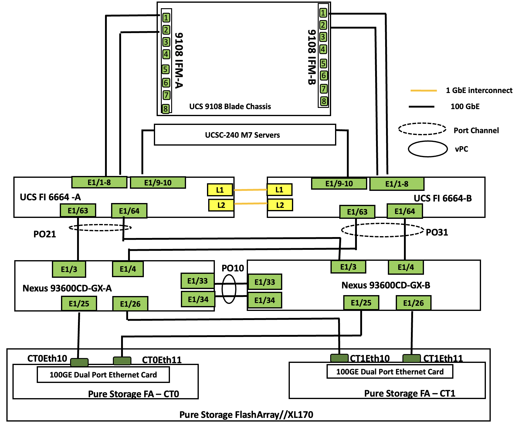
The topology for greenfield deployment is validated using Cisco UCS X210 M7 and Cisco UCSC-C240 M7 servers connected to Pure Storage FlashArray//XL170 through Nexus 93600CD-GX series switches utilizing NVMe-over-Fabric (NVMe-oF) protocol over TCP transport.
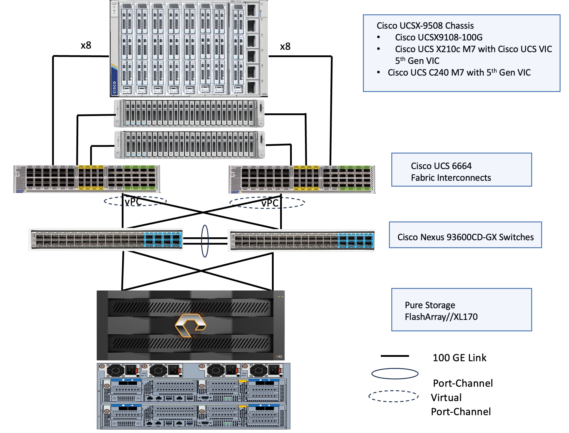
The reference hardware configuration includes:
● Cisco UCS X9508 chassis, equipped with a pair of Cisco UCS X9108 100G IFMs and Cisco UCS X210c M7 compute nodes. Each compute node is equipped with fifth-generation Cisco UCS VIC card 15231 providing 100G ethernet connectivity on each side of the fabric. Cisco VIC is configured with required vNICs for enabling network as well as storage access using NVMe-oF protocol over TCP.
● Cisco UCS C240 server validated for this solution. Cisco UCS C240 M7 server is a dual socket server that support up to 32 memory DIMMs and a maximum of 128 cores per node. The Cisco UCS C-Series servers are ideal for cpu-intensive and memory-intensive workloads that benefit from dual-CPU configurations. Both Cisco UCS C240 servers are equipped with Cisco UCS 5th Gen VIC 15237 dual port 40/100Gbps mLOM network card. Cisco UCS VIC is configured with required vNICs for enabling network as well as storage access using NVMe-oF protocol over TCP.
● Cisco 6th generation 6664 Fabric Interconnects (FIs) are used to provide connectivity to both blade and rack servers. These FIs are configured in End-Host mode acting like a host (not a traditional switch) to the upstream network, optimizing traffic flow and simplifying network management. The FIs are connected to the upstream Nexus switches using 100Gbps ports for both management and storage traffics.
● A pair of Nexus C93600CD-GX switches are used in Virtual Port Channel (vPC) mode. This high-speed Cisco NXOS-based Nexus C93600CD-GX switching design supports up to 100 and 400-GE connectivity.
● Pure Storage FlashArray//XL170 is used as external storage for providing persistent storage for virtual machines hosted on the Nutanix cluster. The storage array controllers are connected to Nexus switches using dual port 100Gbps network cards for storage access over NVMe over Fabric protocol over TCP.
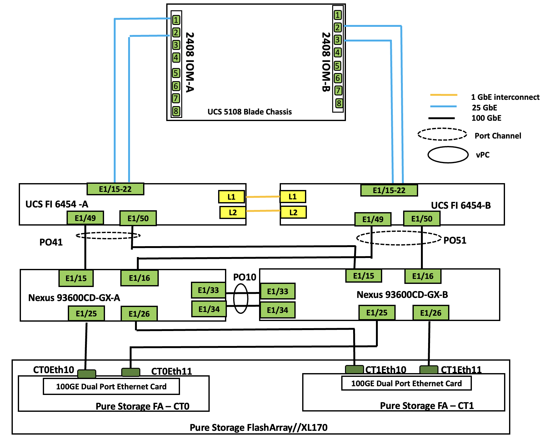
The topology for brownfield deployments is built using already existing Cisco UCS B200 M5 or Cisco UCS B200 M6 blade servers. Figure 4 shows the brownfield deployment validated using Cisco UCS B200 M5 and B200 M6 blades connected to Pure Storage FlashArray//XL170 through Nexus 9000 series switches utilizing NVMe over Fabric (NVMe-oF) protocol over TCP.
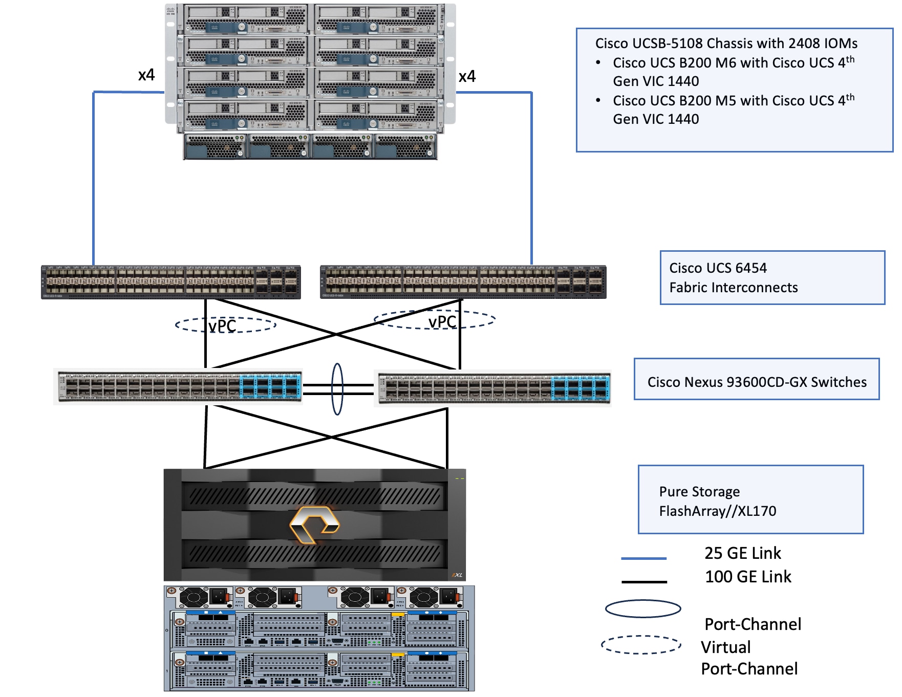
The reference hardware configuration includes:
● Cisco UCSB-5108 chassis, equipped with a pair of Cisco UCS-IOM-2408 modules and up to eight Cisco UCS B200 M6 and M5 compute nodes. Each compute node is equipped with 4th generation Cisco UCS VIC 1440 card providing 40Gbps ethernet connectivity to the blade on each side of the fabric. Cisco UCS VIC is configured with required vNICs for enabling network as well as storage access using NVMe-oF protocols over TCP.
● Cisco 4th generation 6454 Fabric Interconnects (FIs) are used to provide connectivity to both blade and rack servers. These FIs are configured in End-Host mode acting like a host (not a traditional switch) to the upstream network, optimizing traffic flow and simplifying network management. The FIs are connected to the upstream Nexus switches using 100Gbps ports (from ports 49 onwards) for both management and storage traffic.
● A pair of Nexus C93600CD-GX switches are used in Virtual Port Channel (vPC) mode. This high-speed Cisco NXOS-based Nexus C93600CD-GX switching design supports up to 100 and 400-GE connectivity.
● Pure Storage FlashArray//XL170 is used as external storage for providing persistent storage for virtual machines hosted on the Nutanix cluster. The storage array controllers are connected to Nexus switches via dual port 100Gbps network interfaces, facilitating high-performance storage access via NVMe-over-Fabric (NVMe-oF) over TCP protocol.
Note: Additional 1Gb management connections are needed for the out-of-band management KVM console access of the hardware. Each Cisco UCS C-Series server, Fabric Interconnects, and Pure Storage controllers are required to be connected to dedicated network switches. These out-of-Band connections and switches are not shown in the above figures.
The information in this section is provided as a reference for cabling the physical equipment in a FlashStack environment.
The compute infrastructure in FlashStack solution consists of the following:
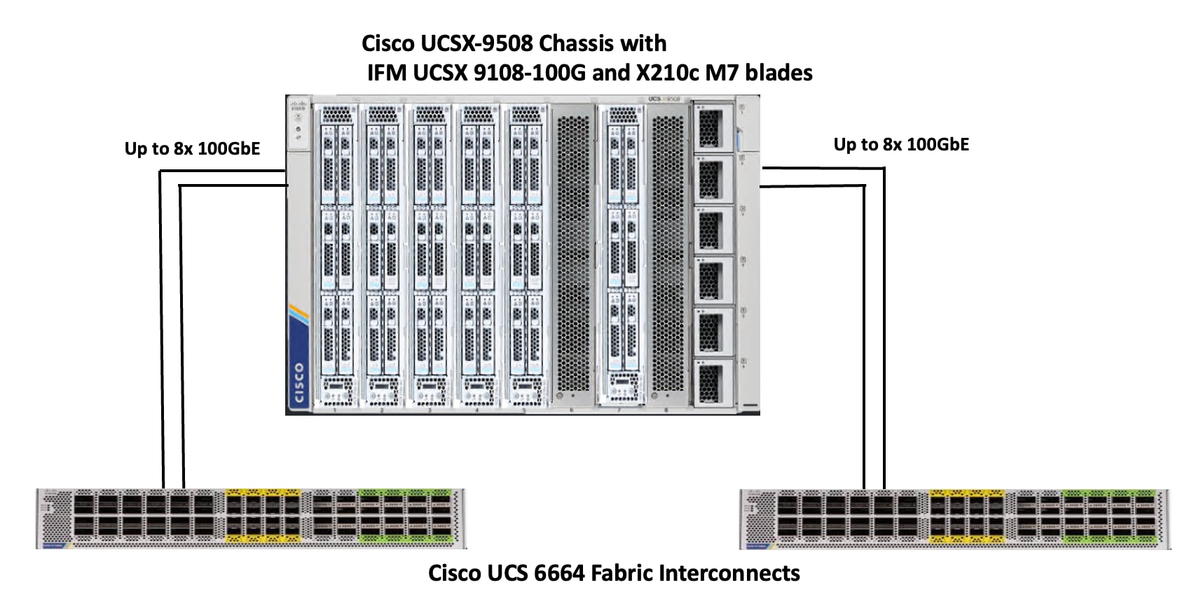
● Cisco UCS X-Series Chassis with Cisco UCSX-9108 Intelligent Fabric Modules and Cisco UCS X210c M7 blades
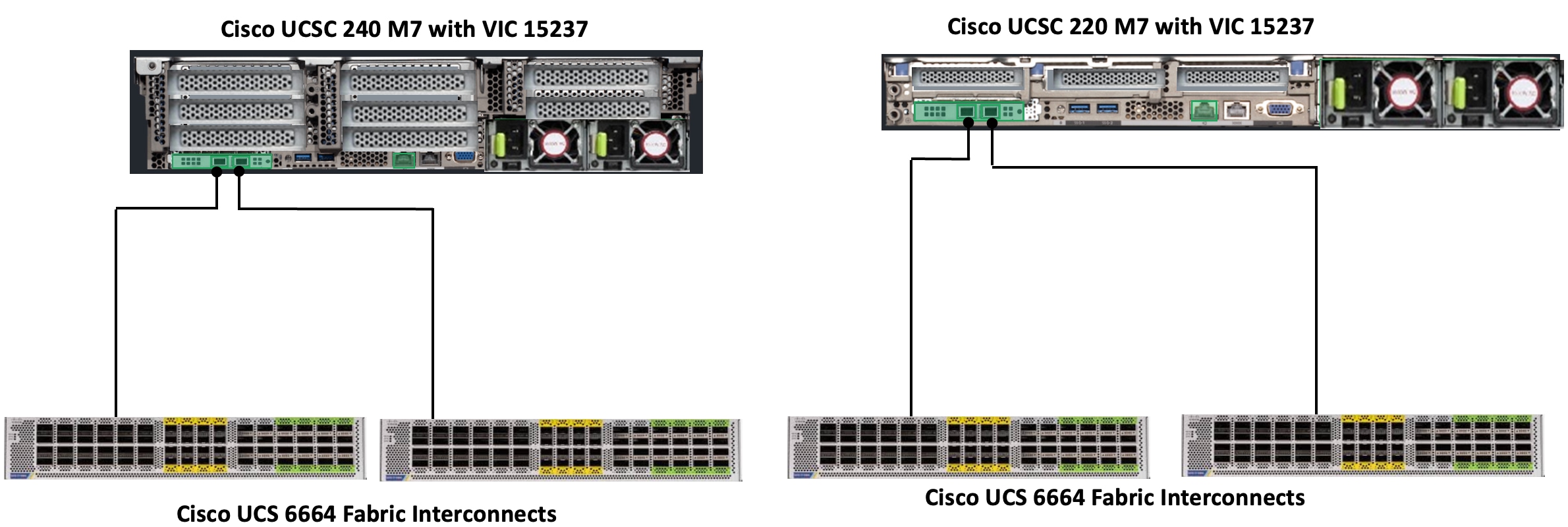
● Cisco UCS C240 M7 and Cisco UCS C220 M7 C-Series Rack servers with Cisco UCS VIC 15237
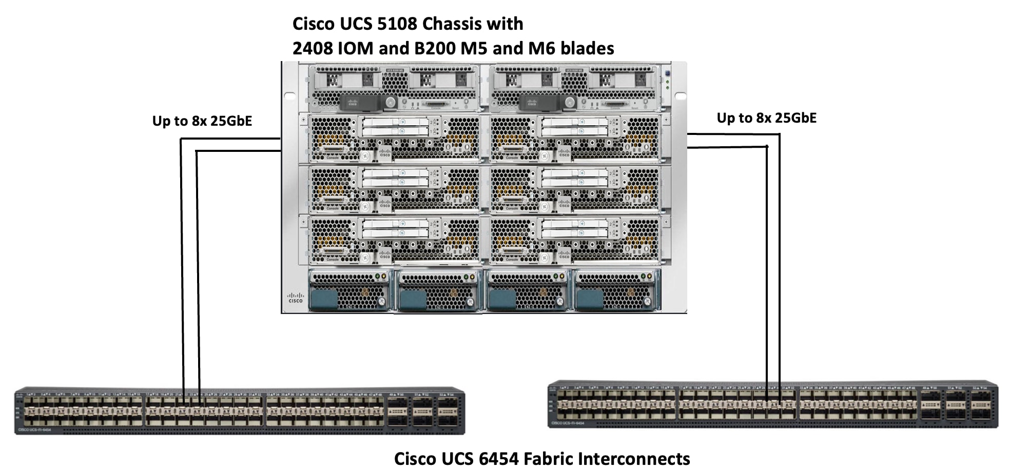
● Cisco UCSC 5108 blade Chassis with IOM 2408 module and Cisco UCS B200 M5 and Cisco UCS B200 M6 blades
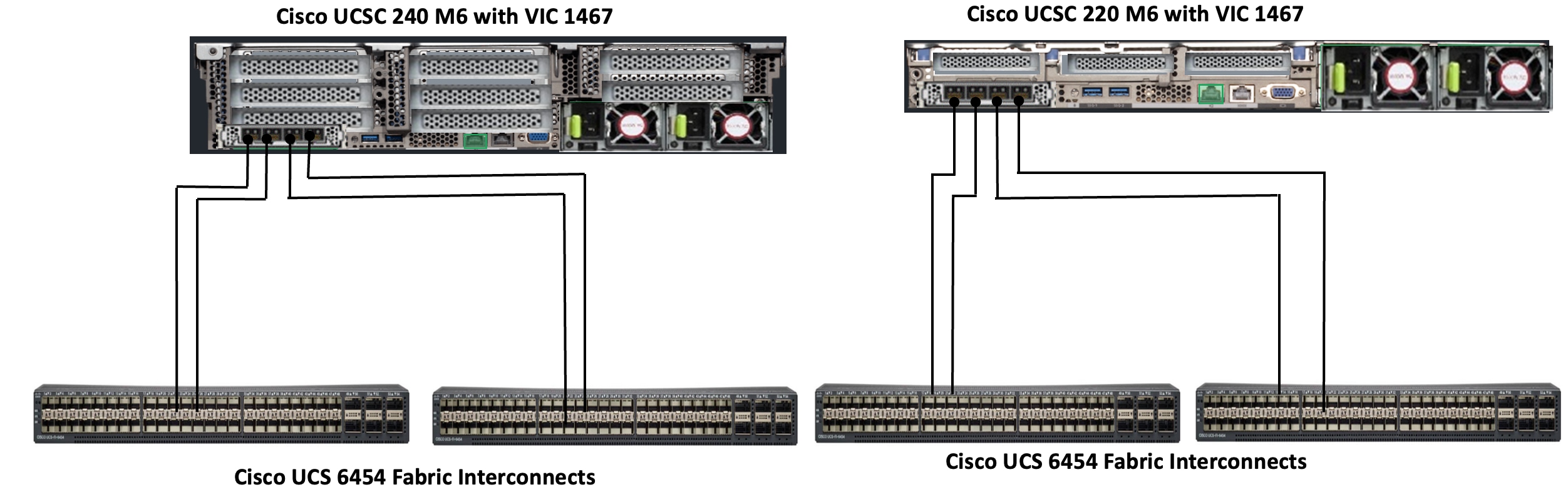
● Cisco UCS C240 M6 and Cisco UCS C220 M6 C-Series Rack servers with Cisco UCS VIC 1467
● Cisco UCS Fabric Interconnects (Cisco UCS-FI-6664 and Cisco UCS-FI-6454)
The Cisco UCS X9508 Chassis is equipped with Cisco UCS X9108-100G intelligent fabric modules (IFMs). The Cisco UCS X9508 Chassis connects to each Cisco UCS 6664 FI using up to eight 100GE ports, as shown in Figure 5. You can start with a minimum of one connection and scale up to eight connections for additional network bandwidth.
Cisco UCS C240 and Cisco UCS C220 M7 C-Series servers are equipped with Cisco UCS 5th Gen VIC 15237 dual port 40/100Gbps mLOM network card. Each Cisco UCS C-Series server is connected to Cisco UCS 6664 FIs using two 100GE ports as shown in Figure 6.
The Cisco UCS 5108 blade chassis is equipped with Cisco UCS 2408-25G IO modules. The Cisco UCS 5108 chassis connects to each Cisco UCS 6454 FI using up to eight 25GE ports, as shown in Figure 7. You can start with a minimum of one connection and scale up to eight connections for additional network bandwidth.
Cisco UCS C240 and Cisco UCS C220 M6 C-Series servers are equipped with Cisco UCS 4th Gen VIC 1467 dual port 10/25Gbps mLOM network card. Each Cisco UCS C-Series server is connected to Cisco UCS 6454 FIs using two 25GE ports as shown in Figure 8.
Note: Multiple options are available for connecting Cisco UCS C-Series rack servers to the Fabric Interconnects. See the FlashStack with Nutanix Installation Field Guide for more details on Cisco UCS C-series connectivity options.
Compute UCS Fabric Interconnect Connectivity
For both deployment types, Cisco UCS Fabric Interconnects are connected to upstream Cisco Nexus switches configured in virtual Port Channel (vPC) mode. This setup provides a link redundancy, load balancing and high availability for network connectivity between UCS domain and the upstream switches. Each FI is connected to both Cisco Nexus 93600CD-GX switches using 100G connections; additional links can easily be added to the port channel to increase the bandwidth as needed. Figure 9 shows the Fabric Interconnect connectivity to the Upstream Nexus switches.
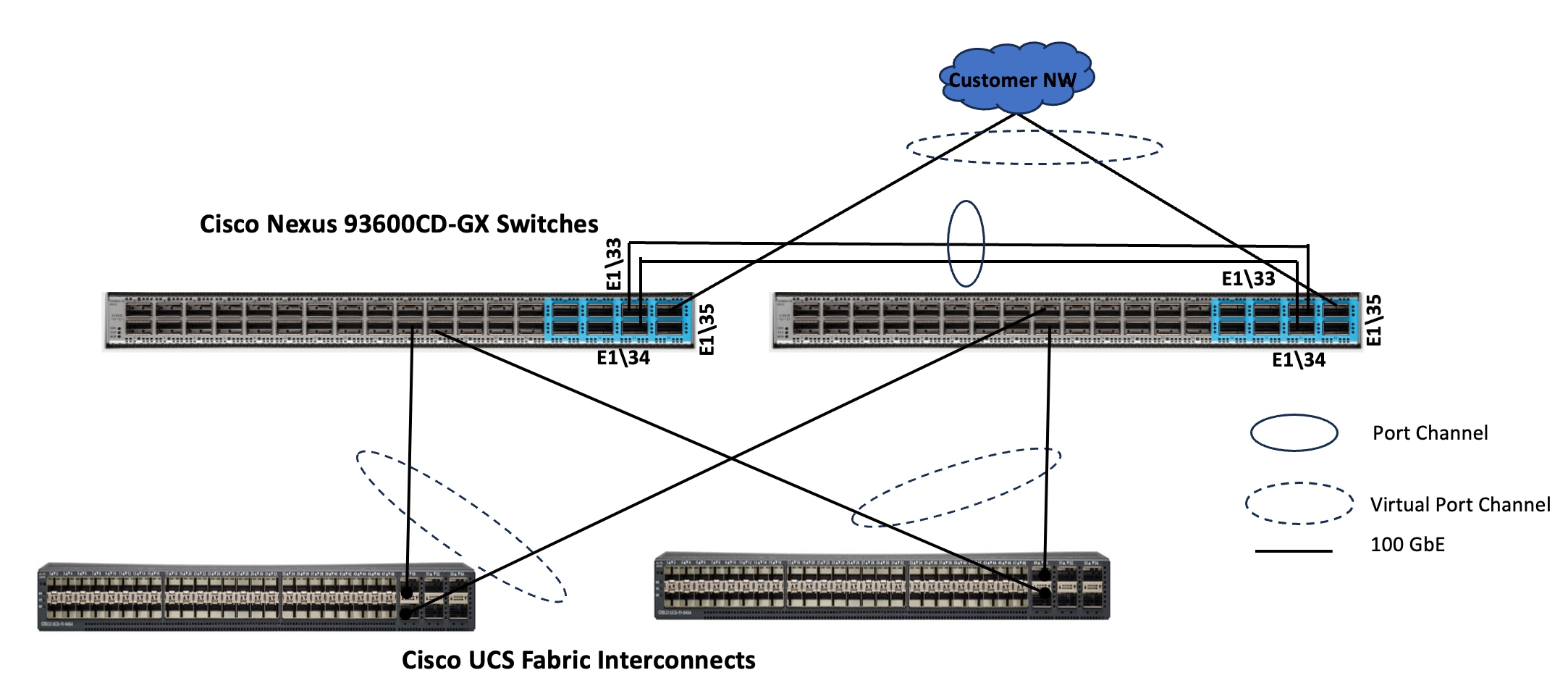
Note: In case of 6454 Fabric Interconnects, leverage the last 6x 100 GbE ports (49 to 54) and for 64108 FIs, leverage last 12x 100GbE ports (97 to 108), to connect to the upstream Cisco Nexus switches. In case of the 6600 or 6500 series Fabric Interconnects, use any 100 GbE non-unified ports for the upstream network connectivity.
Pure Storage FlashArray//XL170 Ethernet Connectivity
Pure Storage FlashArray controllers are connected to Cisco Nexus 93600CD-GX switches using redundant 100Gbs ports. Figure 10 illustrates the physical connectivity details.
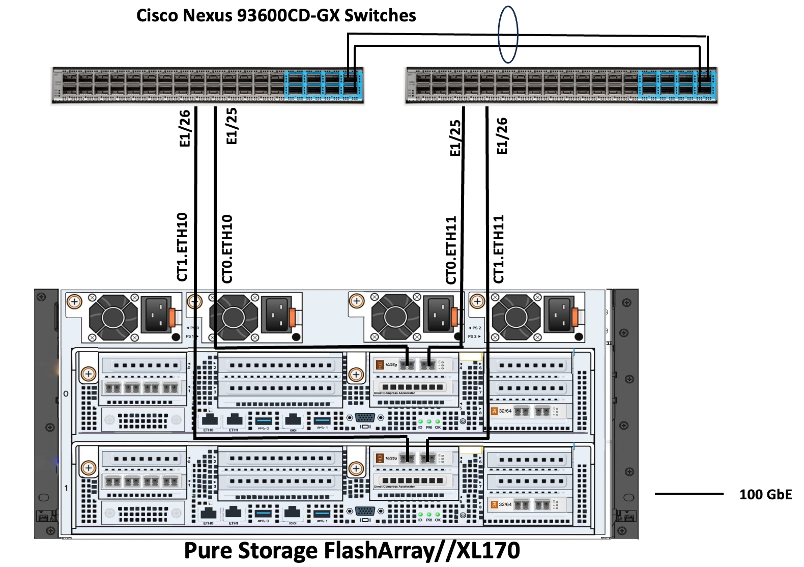
Figure 11 details the cable connections used in the validation lab for the FlashStack topologies.
FlashStack with Nutanix Networking
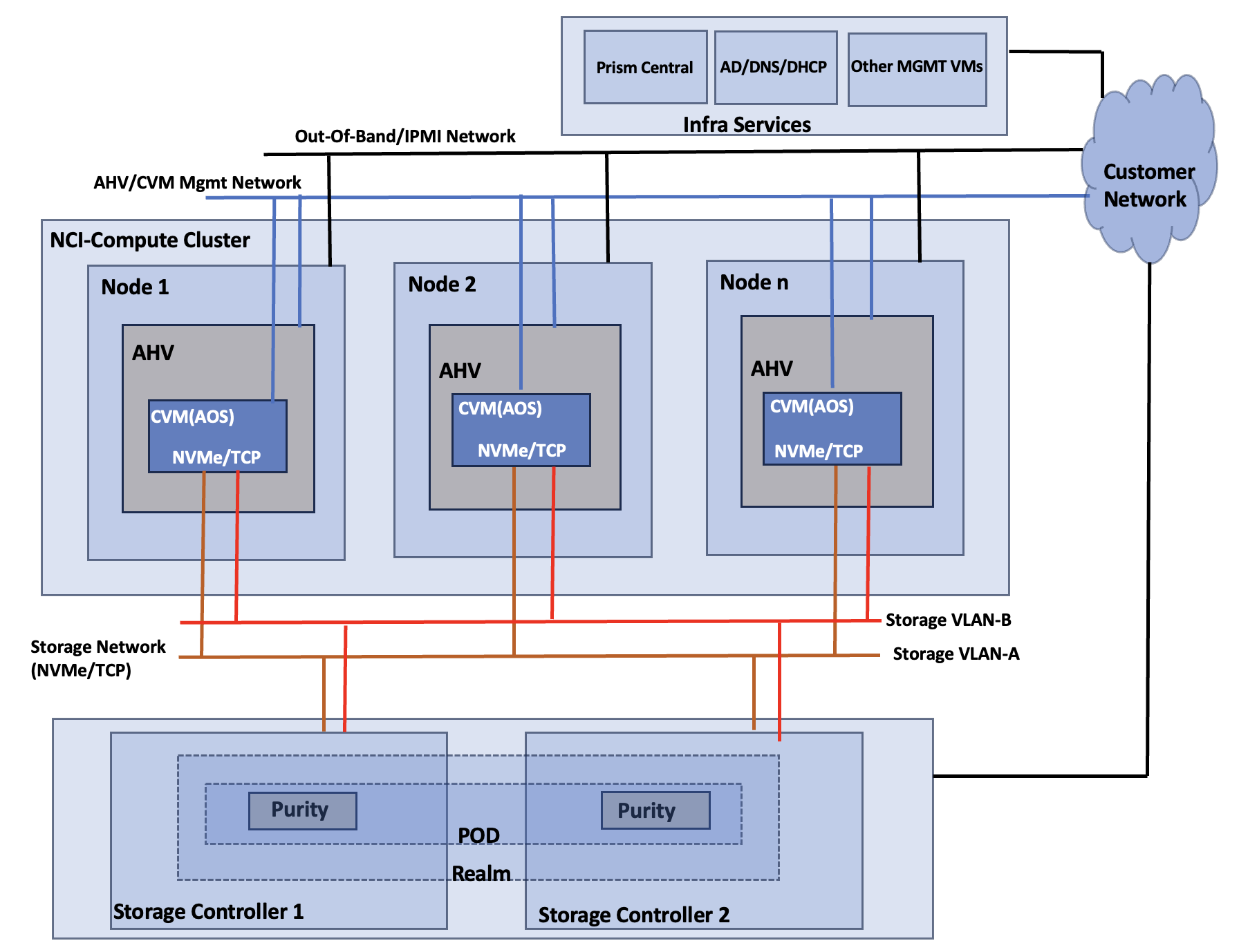
Figure 13 shows high level logical architecture of the FlashStack with NCI compute cluster. The AOS Controller VMs are connected to Pure Storage FlashArray over a dedicated network using two different VLANs/Subnets. Both AHV nodes and Controller VMs are connected to a management network for in-band management. All the hardware platforms including servers and storage controllers are connected to a dedicated out-of-band management or IPMI network for KVM console access and management.
NCI Compute Cluster Node Networking
The networking topology leverages the unique VIC technology of Cisco UCS to provide a highly granular and secure networking environment for Nutanix clusters. By defining multiple pairs of vNICs in the Cisco UCS Service Profile, different types of traffic can be physically isolated before they even reach the hypervisor. For instance, external storage traffic can be segregated from Guest VM traffic by creating a dedicated pair of vNICs. Similarly, Guest VMs traffic can be segregated from the hypervisor (AHV) and controller VM (CVM) management traffic.
Using a UCS LAN connectivity policy, six vNICs are created to carry different types of traffic. Table 4 lists the details about the vNICs configured for each Nutanix node. For detailed steps to create these policies, see chapter Install and Configure.
Table 4. LAN Connectivity Policy and vNICs
| vNIC Name |
ntnx-infra-1-A |
ntnx-infra-1-B |
ntnx-guestvm-A |
ntnx-guestvm-B |
ntnx-storage-A |
ntnx-storage-B |
| Purpose |
management traffic of Nutanix nodes and Controller VMs, VM Live migration |
Guest VM management and Application traffic |
External storage traffic via Fabric-A |
External storage traffic via Fabric-B |
||
| Name of the emulated vNIC inside AHV node |
eth0 |
eth1 |
eth2 |
eth3 |
eth4 |
eth5 |
| Switch ID |
A |
B |
A |
B |
A |
B |
| PCI Order of the vNIC |
0 |
1 |
2 |
3 |
4 |
5 |
| CDN Source setting |
vNIC Name |
vNIC Name |
vNIC Name |
vNIC Name |
vNIC Name |
vNIC Name |
| Fabric Failover setting |
Disabled |
Disabled |
Disabled |
Disabled |
Disabled |
Disabled |
| MAC Pools |
Name: ntnx-mac-pool-common (used same pool for all the pairs of vNICs) |
|||||
| Network Group Policy name and Allowed VLANs and Native VLAN |
Name: ntnx-infra-eth-nwgrp: Allowed VLAN: 1061 |
Name: ntnx-guestvm-nwgrp: Allowed VLAN: 1062,1063,1064
|
Name: ntnx-storage-nwgrp: Allowed VLANs: 3010,3020 |
|||
| Network Control Policy Name and CDP and LLDP settings |
Name: ntnx-eth-nwcontrol: CDP Enabled LLDP (Tx and Rx) Enable |
|||||
| QoS Policy name and Settings |
Ntnx-QoS: Priority: Best Effort Class of Service: 0 MTU: 9000 Rate Limit (Mbps): 0 |
|||||
| Ethernet Adapter Policy Name and Settings |
Name: ntnx-eth-adapter-policy Uses system defined Policy: Linux-V2 with following changes EtherChannel Pinning: Enables Transmit Queues: 2 Complete Queues: 10 |
|||||
Note: Using LAN Connectivity policies, additional vNICs can be configured for other various traffics such as DR Replication, backup etc. If not, default vs0 switch can be leveraged and configured to accommodate the other traffic as well.
Figure 14 depicts the vNICs configured for the NCI Nutanix node for this validation.
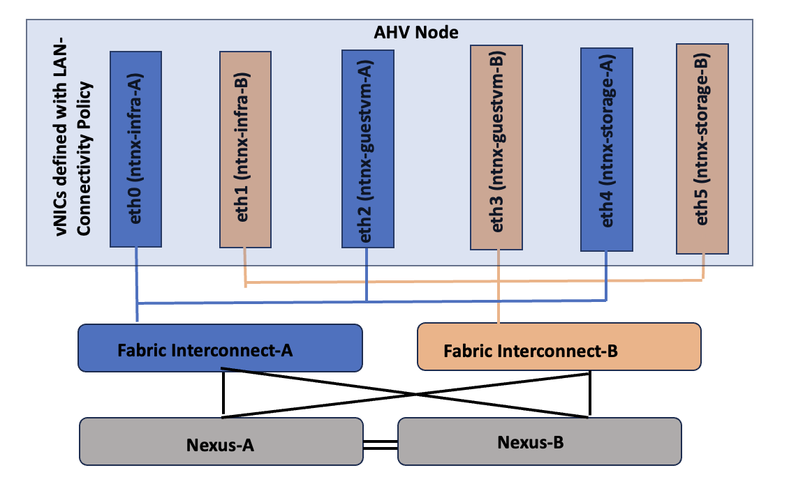
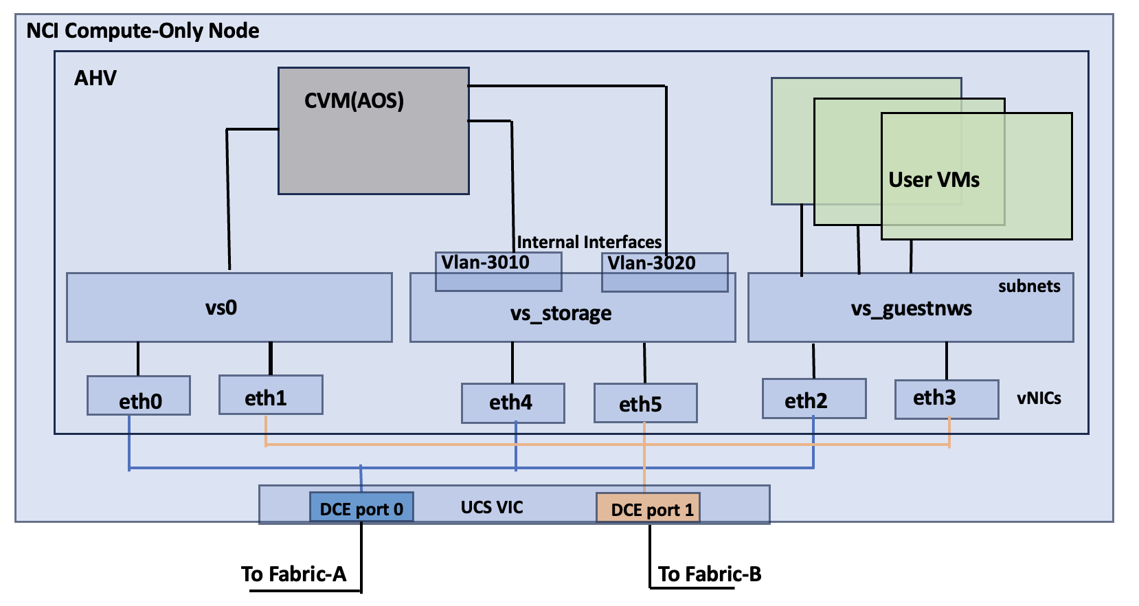
Table 5 lists the details about the virtual switch configuration within the NCI Compute Cluster node.
Table 5. Nutanix AHV Networking
| vNIC Name |
Enumerated AHV Interface Name |
vSwitch Configuration |
| ntnx-infra-1-A |
eth0 |
vSwitch Name: vs0 Bond Type: Active-Backup VLANs: 1061 |
| ntnx-infra-1-B |
eth1 |
|
| ntnx-guestvm-A |
eth2 |
vSwitch Name: vs_guestnws MTU: 1500 Bond Type: Active-Backup or Active-Active with MAC Pinning VLANs: 1062,1063,1064 etc. |
| ntnx- guestvm -B |
eth3 |
|
| ntnx-storage-A |
eth4 |
vSwitch Name: vs_storage Bond Type: Active-Active with MAC Pinning MTU: 9000 VLANS: 3010 (eth4), 3020 (eth5) |
| ntnx- storage -B |
eth5 |
Note: With in the UCS domain (between the Cisco UCS servers and FIs), the Nutanix virtual switches cannot be configured with Active-Active (LACP) bond type. Either Active-Backup or Active-Active with MAC Pinning must be used.
Figure 15 illustrates the internal networking configuration of each NCI Cluster Compute node. Within each Nutanix AHV node, Virtual Switch (vs0) is created using eth0 and eth1 uplink interfaces with an active-backup bond type. For FlashArray storage traffic, a dedicated vSwitch (vs_storage) is created using eth4 and eth5 uplink interfaces in Active-Active with Mac Pinning option. With in the vs_storage vSwitch, two internal interfaces are created for VLANS 3010 and 3020 for establishing highly available and performant storage data paths. For guest VM management and application traffic, a third Virtual Switch is created using uplink interfaces eth2 and eth3 with Active-backup or Active-Active with MAC Pinning configuration.
FlashStack with Nutanix Storage Layout
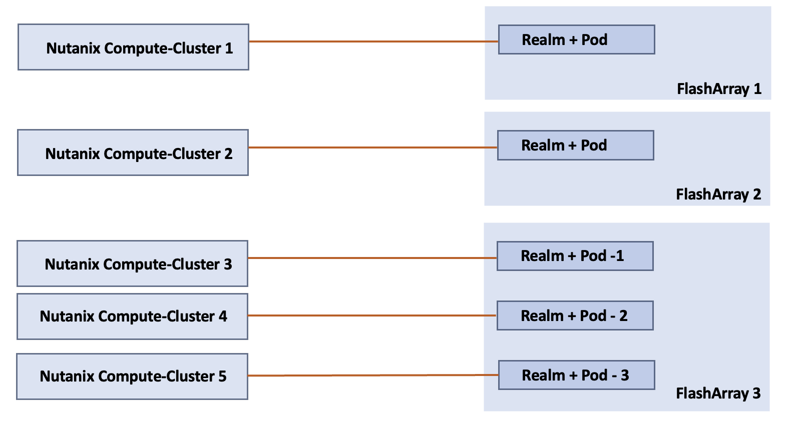
In the FlashStack with Nutanix architecture, an NCI compute cluster is connected to Pure Storage FlashArray’s “Realm+Pod” combination. In the Pure//FA Operating System, Realms and Pods are the fundamental building blocks for achieving Secure Multi-Tenancy (SMT) and Advanced Data Protection. While they are often used together, they serve two distinct purposes:
● Realm: It allows multiple organizations or departments to share a single higher-performance FlashArray without seeing each other’s data or accidentally deleting each other’s volumes. It allows administrators to carve up a FlashArray into multiple independent tenants (for example, Department A, Project B, Client C). They logically group the volumes, users & roles, Resource Quotas, Quality of Services (QoS) and Network Interfaces. Pure Storage implements access control using Role Based Access Control (RBAC) by creating permissions to the roles, which are then assigned to users or groups. Each Realm can have its own administrator and independent Active Directory/LDAP/NIS authentication configuration.
● Pod: is a management container that provides data consistency and mobility (replication). Each tenant can have more than one pod (for example, K8s-cluster, Oracle-cluster and so on).
By placing a Pod inside a Realm, application’s data is highly available (via Pod) while remaining securely isolated and quota-restricted (using Realm).
Note: NCI Compute clusters support a one-to-one or many-to-one relationship with FlashArrays. A cluster is restricted to a single Realm+Pod combination on one FlashArray; however, a FlashArray can serve multiple NCI Compute Clusters using different Realm+Pod combinations.
The mapping between NCI Compute Cluster, FlashArray and Realm+Pod combinations is illustrated in Figure 16.
NCI Compute Cluster Storage Internal Networking
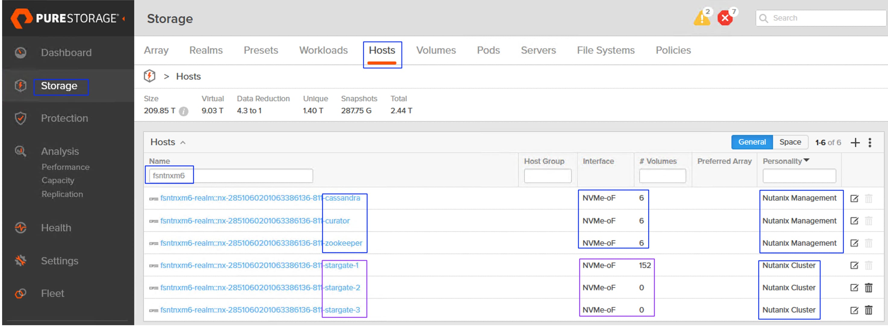
Stargate, Curator, Zookeeper and Cassandra are some of key software components that run as services within each AOS Nutanix Controller VM (CVM), working together to manage data, cluster configuration, and background tasks in the distributed storage fabric. For more details about these services, see The Nutanix Cloud Bible. The storage for the services (Zookeeper, Curator and Cassandra) are typically created on the M.2 boot disk of each Nutanix node during Nutanix Cluster provisioning.
However, in the NCI Compute Cluster architecture ,to maintain a stateless footprint on the Cisco UCS Compute nodes, the storage of these core metadata and configuration services -Zookeeper, Curator and Cassandra- is offloaded to the Pure Storage FlashArray. One volume for each service is created per node on the FlashArray. These volumes are then attached to the corresponding individual CVMs via the Pure Storage Host/Initiator group, providing a highly available and scalable environment for the cluster’s metadata and management services. These volumes are referred as kernel volumes and are attached to corresponding controller VMs using NVMe/TCP initiators running in the kernel space.
In the NCI Compute Cluster, each virtual disk (vDisk) is architecturally represented on the Pure Storage FlashArray by a dual-volume pairing: a Primary Data Volume (-dt) and a Metadata volume (-md). This 1:2 mapping ensures granular data management and integrity. Connectivity to guest VMs is established via the Controller VM (CVM), which leverages high-performance NVMe/TCP initiators running in user space. By passing the kernel overhead, this design delivers near-native storage performance to the Guest VMs while maintaining the full suite of Nutanix enterprise data services.
A total of eighteen (6x3) services volumes created and mapped to corresponding service types on a 6-node NCI Compute Cluster (below). Three Stargate hosts/initiatorgroups are created to map the user volumes to the Guest VMs.
When a user volume is cloned (by cloning a VM via Prim Central/Element), two corresponding volumes (-dt and -md) will be created in the FlashArray. While a snapshot of a volume (by taking a snapshot of the VM from Prism Central) will have just one volume created in the FlashArray.
This chapter contains the following:
● Cisco Nexus Switch Configuration
● Claim Cisco Nexus Switches into Cisco Intersight
● Pure Storage FlashArray Configuration
● Cisco Intersight Configuration
● Fabric Interconnect Domain Profile and Policies
● Create Pools, Policies for LAN Connectivity Policy
● Select Nutanix Installation Method
● Install NCI Compute Cluster on FlashStack
● Configure External Storage Array Connectivity
● Configure Virtual Machine Networking
● Modify Default Passwords on AHV and CVMs
● Prism Central Installation and Configuration
● Install Device Connector in Prism Central
● NCI Compute Cluster Expansion using Prism Central
● Physical cabling should be completed by following the diagram and table references in section FlashStack Cabling. The following procedures assume that all the FlashStack components are connected to a dedicated Out-Of-Band/IPMI network for KVM session access.
● The procedures in this chapter describe how to configure the Cisco Nexus 93600CD-GX switches for use in a FlashStack environment. This procedure assumes Fabric Interconnects firmware and Cisco Nexus switches NXOS is upgraded to the supported versions.
● The procedure includes the setup of NTP distribution on both the mgmt0 port and the in-band management VLAN. The interface-vlan feature and ntp commands are used to set this up..
● This document assumes that initial day-0 switch configuration is already done using switch console ports and ready to use the switches using their management IPs.
● This document assumes that initial day-0 Pure Storage FlashArray configuration is already done using console ports and ready to use the Pure Storage Management Console using their virtual management IP.
● It is recommended to list and note all VLANs, and IP addresses for Nutanix cluster provisioning. Table 6 lists the supporting components or modules used for deploying the solution.
Table 6. Supporting Components used for NCI Compute Cluster Deployments
| Component or Module Name |
IP address |
| Pure Storage FlashArray Virtual IP(VIP) |
10.103.0.55 |
| FlashArrays Controller’s Ethernet Ports IP subnets |
192.168.31.0/24 (CT0.Eth10,CT1.Eth10) |
| Foundation Central VM appliance |
10.106.1.50 |
| DNS IP |
10.106.1.21 |
| NTP IP |
172.10.20.11 |
| Prism Central VM IP |
10.106.2.5 |
| NCI Compute Cluster Virtual IP (Greenfield-M7 setup) Cluster Name: fs-ntnx |
10.106.1.70 |
| Data services IP (M7 setup) |
10.106.1.69 |
| NCI Compute Cluster Virtual IP (Brownfield-M5/M6 setup) Cluster Name: fs-m6-ntnx |
10.106.1.90 |
| Data services IP (M5/M6 setup) |
10.106.1.89 |
| Intersight Assist |
10.106.1.51 |
| Cisco UCS IMM Transition Toolkit |
10.106.1.24 |
Table 7 lists the IP addresses used for the two deployment types (greenfield and brownfield).
Table 7. IP Addresses used for the NCI Compute Cluster Deployments
| Host Name |
AHV Hypervisor IP |
CVM IP |
Out-Of-Band IP Address |
| Greenfield Deployment: fs-ntnx (10.106.1.70), Gateway: 10.106.1.254 and Netmask: 255.255.255.0 |
|||
| fsntnx-n1 |
10.106.1.71/24 |
10.106.1.81/24 |
10.106.0.60/24 |
| fsntnx-n2 |
10.106.1.72/24 |
10.106.1.82/24 |
10.106.0.61/24 |
| fsntnx-n3 |
10.106.1.73/24 |
10.106.1.83/24 |
10.106.0.62/24 |
| fsntnx-n4 |
10.106.1.74/24 |
10.106.1.84/24 |
10.106.0.63/24 |
| fsntnx-n5 |
10.106.1.75/24 |
10.106.1.85/24 |
10.106.0.64/24 |
| fsntnx-n6 (used for cluster expansion) |
10.106.1.76/24 |
10.106.1.86/24 |
10.106.0.65/24 |
| Brownfield Deployment: fs-m6-ntnx (10.106.1.90), Gateway: 10.106.1.254 and Netmask: 255.255.255.0 |
|||
| fs-m6-ntnx-n1 |
10.106.1.91/24 |
10.106.1.101/24 |
10.103.0.101/24 |
| fsm6-ntnx-n2 |
10.106.1.92/24 |
10.106.1.102/24 |
10.103.0.102/24 |
| fsm6-ntnx-n3 |
10.106.1.93/24 |
10.106.1.103/24 |
10.103.0.103/24 |
| fsm6-ntnx-n4 |
10.106.1.94/24 |
10.106.1.104/24 |
10.103.0.104/24 |
| fsm6-ntnx-n5 |
10.106.1.95/24 |
10.106.1.105/24 |
10.103.0.105/24 |
| fsm6-ntnx-n6 (used for cluster expansion) |
10.106.1.96/24 |
10.106.1.106/24 |
10.103.0.106/24 |
Cisco Nexus Switch Configuration
This section assumes that a pair of Nexus Switches are already configured and accessible using their management Ips. Follow the procedures listed below to configure the Nexus switches.
Note: For brownfield deployments, it is assumed that the Top-Of-Rack (ToR) switches are already configured to support the existing infrastructure. Therefore, switch configuration steps for brownfield deployment type, are not included in the following procedures. Ensure all the required VLANs for management, storage and guest traffics are defined in the switches.
Procedure 1. Enable Features on Cisco Nexus Switches A and B
Step 1. Log into both Nexus switches as admin using ssh.
Step 2. Enable the switch features as described:
config t
feature nxapi
cfs eth distribute
feature udld
feature interface-vlan
feature netflow
feature hsrp
feature lacp
feature vpc
feature lldp
Procedure 2. Set Global Configurations on Enable Features on Cisco Nexus Switches A and B
Step 1. Run the following commands to set the global configurations:
spanning-tree port type edge bpduguard default
spanning-tree port type edge bpdufilter default
spanning-tree port type network default
system default switchport
system default switchport shutdown
port-channel load-balance src-dst l4port
ntp server <Global-ntp-server-ip> use-vrf management
ntp master 3
clock timezone <timezone> <hour-offset> <minute-Offset>
clock summer-time <timezone> <start-weekk> <start-day> <start-month> <start-time> <end-week> <end-day> <enb-month> <end-time> <offset-minutes>
ip route 0.0.0.0/0 <IB-Mgmt-VLAN-gatewayIP>
copy run start
Note: For more information on configuring the timezone and daylight savings time or summer time, see: Cisco Nexus 9000 Series NX-OS Fundamentals Configuration Guide, Release 10.3(x) - Basic Device Management.
Procedure 3. Create VLANs on Cisco Nexus Switches A and B
Step 1. From the global configuration mode, run the following:
Vlan <oob-mgmt-vlan-id> #1060
name OOB-Mgmt-VLAN
Vlan <iB-mgmt-vlan-id> #1061
name IB-Mgmt-VLAN
Vlan <native-vlan-id> #2
name Native-VLAN
Vlan <NVMe-TCP_A-vlan-id> #3010
name NVMe-TCP_A
Vlan <NVMe-TCP_B-vlan-id> #3020
name NVMe-TCP_B
Vlan <vm-mgmt1-vlan-id> #1062
name VM-Mgmt1
Vlan <vm-mgm2t-vlan-id> #1063
name VM-Mgmt2
Vlan <vm-mgm2t-vlan-id> #1064
name VM-Mgmt3
Procedure 4. Define Port Channels on Cisco Nexus A and B
Step 1. From the global configuration mode, run the following:
##This Port Channel (PO) is for VPC configuration; Execute the below commands on both the switches A & B
interface port-channel 10
description vPC Peer Link
switchport mode trunk
switchport trunk native vlan 2
switchport trunk allowed vlan 1060-1064,3010,3020
spanning-tree port type network
## This PO is for FI-6664-A/B to Nexus Switches connectivity for greenfield deployment type; Execute the ##below commands on both the switches A & B
interface port-channel 21
switchport mode trunk
switchport trunk native vlan 2
switchport trunk allowed vlan 1060-1064,3010,3020
spanning-tree port type edge trunk
mtu 9216
interface port-channel 31
switchport mode trunk
switchport trunk native vlan 2
switchport trunk allowed vlan 1060-1064,3010,3020
spanning-tree port type edge trunk
mtu 9216
### Optional: The below port channels is for connecting the Nexus switches to the existing customer network; ##Execute the below commands on both the switches A & B
interface port-channel 106
description connecting-to-customer-Core-Switches
switchport mode trunk
switchport trunk native vlan 2
switchport trunk allowed vlan 1060-1064
spanning-tree port type normal
mtu 9216
Procedure 5. Configuring Virtual Port Channel (VPC) Domain on Cisco Nexus Switches A and B
Step 1. Run the following commands to set the global configurations:
## Execute the following commands on Nexus-A
vpc domain <nexus-vpc-domain-id>
peer-switch
role priority 10
peer-keepalive destination <Switch-B-Mgmt-IP> source <Switch-A-Mgmt-IP>
delay restore 150
peer-gateway
auto-recovery
ip arp synchronize
## Execute the following commands on Nexus-B
vpc domain <nexus-vpc-domain-id>
peer-switch
role priority 20
peer-keepalive destination <Switch-A-Mgmt-IP> source <Switch-B-Mgmt-IP>
delay restore 150
peer-gateway
auto-recovery
ip arp synchronize
Procedure 6. Configure individual Interfaces on Switches A and B
Step 1. From the global configuration mode, run the following:
## Execute the below commands on Switch-A
### FI-6664 Ports for greenfield configuration
interface Ethernet1/3
description FI6664-A-uplink-Eth63
channel-group 21 mode active
no shutdown
interface Ethernet1/4
description FI6664-B-uplink-Eth63
channel-group 31 mode active
no shutdown
## Configuration for FA//XL170 Storage Ports
interface Ethernet1/25
description PureFAXL170-CT0.ETH10
switchport access vlan 3010
spanning-tree port type edge
mtu 9216
no shutdown
interface Ethernet1/26
description PureFAXL170-CT1.ETH10
switchport access vlan 3010
spanning-tree port type edge
mtu 9216
no shutdown
## Optional: Configuration for interfaces that connected to the customer existing management network
interface Ethernet1/35/1
description customer-Core-1:Eth1/37
channel-group 106 mode active
no shutdown
interface Ethernet1/35/2
description customer-Core-2:Eth1/37
channel-group 106 mode active
no shutdown
### Execute the below commands on Switch-B
### FI-6664 Ports for greenfield configuration
interface Ethernet1/3
description FI6664-A-uplink-Eth64
channel-group 21 mode active
no shutdown
interface Ethernet1/4
description FI6664-B-uplink-Eth64
channel-group 31 mode active
no shutdown
## Configuration for FA//XL170 Storage Ports
interface Ethernet1/25
description PureFAXL170-CT0.ETH11
switchport access vlan 3020
spanning-tree port type edge
mtu 9216
no shutdown
interface Ethernet1/26
description PureFAXL170-CT1.ETH11
switchport access vlan 3020
spanning-tree port type edge
mtu 9216
no shutdown
## Optional: Configuration for interfaces that connected to the customer existing management network
interface Ethernet1/35/1
description customer-Core-1:Eth1/38
channel-group 106 mode active
no shutdown
interface Ethernet1/35/2
description customer-Core-2:Eth1/38
channel-group 106 mode active
no shutdown
Procedure 7. Update the port channels
Step 1. From the global configuration mode, run the following:
## Execute the following commands on Switch A & B
interface port-channel 10
vpc peer-link
interface port-channel 21
vpc 21
interface port-channel 31
vpc 31
interface port-channel 41
vpc 41
interface port-channel 51
vpc 51
interface port-channel 106
vpc 106
copy run start
Claim Cisco Nexus Switches into Cisco Intersight
Cisco Nexus switches can be claimed into Cisco Intersight using Cisco Intersight Assist or Direct claim using Device ID and Claim Codes.
This section provides the steps to claim the Cisco Nexus switches using Cisco Intersight Assist.
Note: This procedure assumes that Cisco Intersight Assist is already hosted in the datacenter and claimed into the Intersight.com. Refer this video for deploying and claiming Intersight Assist into Intersight SAAS platform.
Procedure 1. Claim Cisco Nexus Switches into Cisco Intersight using Cisco Intersight Assist
Cisco Nexus - A
Step 1. Log into Nexus Switches and confirm the nxapi feature is enabled:
show nxapi
nxapi enabled
NXAPI timeout 10
HTTPS Listen on port 443
Certificate Information:
Issuer: issuer=C = US, ST = CA, L = San Jose, O = Cisco Systems Inc., OU = dcnxos, CN = nxos
Expires: Sep 12 06:08:58 2024 GMT
Step 2. Log into Cisco Intersight with your login credentials. From the drop-down list select System.
Step 3. Under Admin, click Target then click Claim a New Target. Under Categories, select Network, click Cisco Nexus Switch and then click Start.
Step 4. Select the Cisco Assist name which is already deployed and configured. Provide the Cisco Nexus Switch management IP address, username and password details and click Claim.
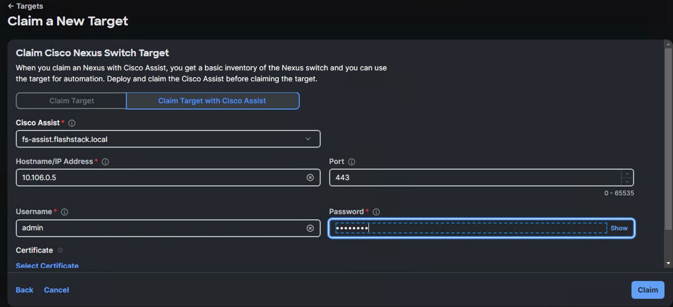
Step 5. Repeat steps 1 through 4 to claim the remaining Switch B.
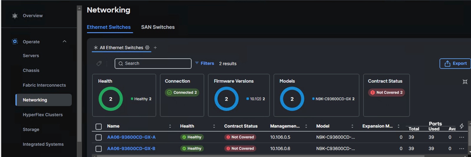
Step 6. When the switches are successfully claimed, from the drop-down list, select Infrastructure Services. Under Operate, click the Networking tab. On the right you will find the newly claimed Cisco Nexus switch details and browse through the Switches for viewing the inventory details.
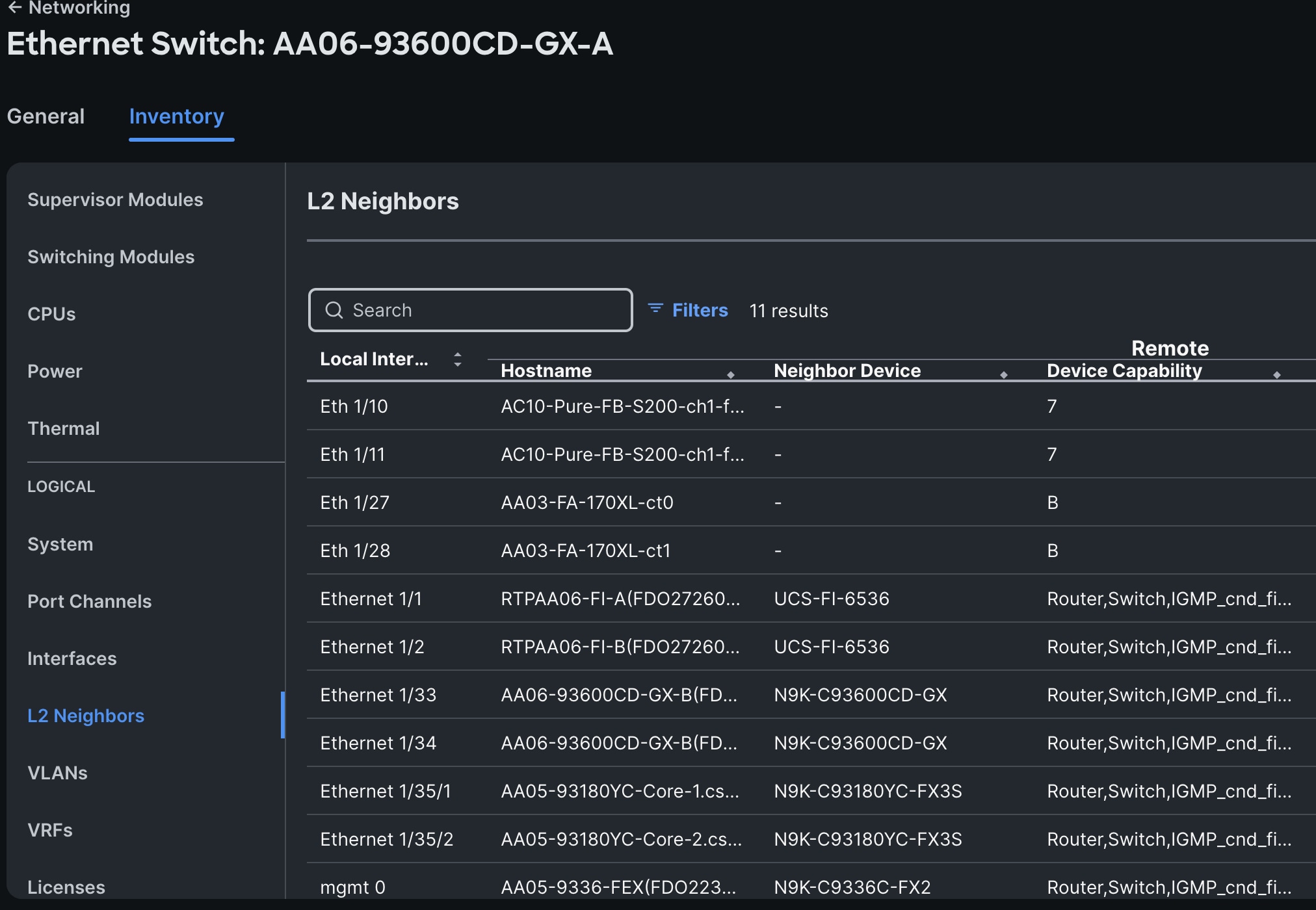
The L2 neighbors of the Cisco Nexus Switch-A is shown below:
Pure Storage FlashArray Configuration
In this solution, Pure Storage FlashArray//XL170 provides storage for all the workloads running on the NCI Compute Clusters for both the deployment types (green and brown fields). This chapter describes the high-level steps to configure Pure Storage FlashArray//X170 network interfaces required for storage connectivity using NVMe over Fabric protocol over TCP. While these procedures specifically details configuration steps for FlashArray //XL170, the configuration steps are substantially similar for other supported models, including the FlashArray //X and //C series.
Note: This document assumes day-0 initial configuration to setup up the storage array is already completed and the FlashArray is accessible using its virtual IP.
As discussed, each storage controller of FlashArray is connected to the pair of Nexus switches using 2x 100GbE ports offering aggregated network bandwidth of 400Gbps from the two controllers. The Pure Storage FlashArray network settings were configured with three subnets across three VLANs. Storage Interfaces CT0.Eth0 and CT1.Eth0 were configured to access management for the storage on VLAN 1030. Storage Interfaces CT0.Eth10, CT1.Eth10, CT0.Eth11 and CT1.Eth11 interfaces are configured with “nvme-tcp” Service. CT0.Eth10 and CT1.Eth10 interfaces are connected to Nexus 93600CD-GX-A switch on port 1/25-26 ports that are configured with access VLAN 3010 while CT0.Eth11 and CT1.Eth11 interfaces are connected to Nexus 93600CD-GX-B switch on port 1/25-26 ports that are configured with access VLAN 3020.
The following tables list the IP addressing configured on the FlashArray //Xl170 controller interfaces used for storage access.
Table 8. Pure Storage FlashArray//XL170 Interface Configuration Settings
| FlashArray Controller |
Port |
IP Address |
Subnet |
| FlashArray//X170 Controller 0 |
CT0.ETH10 |
192.168.31.100 |
255.255.255.0 |
| FlashArray//X170 Controller 1 |
CT1.ETH10 |
192.168.31.101 |
255.255.255.0 |
Table 9. Pure Storage FlashArray//XL170 Interface Configuration Settings
| FlashArray Controller |
Port |
IP Address |
Subnet |
| FlashArray//X170 Controller 0 |
CT0.ETH11 |
192.168.32.100 |
255.255.255.0 |
| FlashArray//X170 Controller 1 |
CT1.ETH11 |
192.168.32.101 |
255.255.255.0 |
Note: The above networking configuration of FlashArray is the simplest configuration and is not the only way to configure FlashArray networking. There are other methods too. FlashArray’s network configuration depends on the infrastructure that customers have. For instance, FlashArray networking can be configured with LACP with a single or multiple subnets or supporting multiple VLANS in trunk mode.
Procedure 1. Configure Storage Interfaces for NVMe-TCP
The following steps are required to configure the controller ports to use nvme-tcp protocol for accessing storage targets.
Step 1. ssh to the Pure FlashArray//Xl170 using its management ip and pureuser credentials.
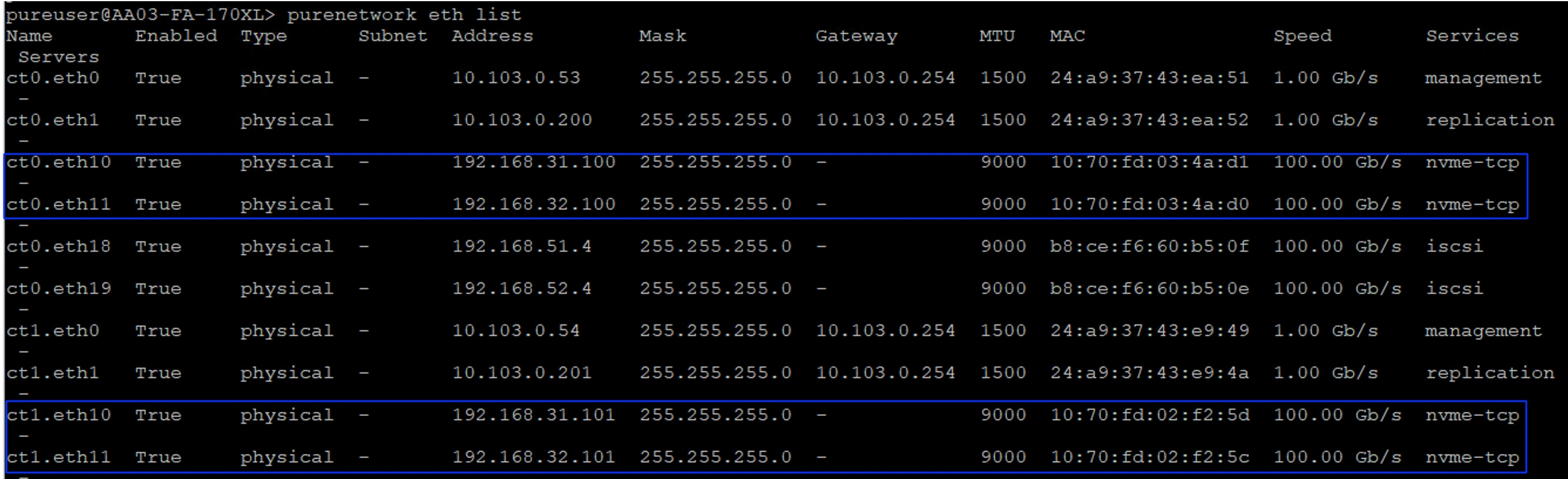
Step 2. Enable nvme-tcp service on all the four ethernet interfaces as shown below:
purenetwork eth enable ct0.eth10
purenetwork eth enable ct0.eth11
purenetwork eth enable ct1.eth10
purenetwork eth enable ct1.eth11
purenetwork eth setattr --address 192.168.31.100/24 --mtu 9000 --servicelist nvme-tcp ct0.eth10
purenetwork eth setattr --address 192.168.32.100/24 --mtu 9000 --servicelist nvme-tcp ct0.eth11
purenetwork eth setattr --address 192.168.31.101/24 --mtu 9000 --servicelist nvme-tcp ct1.eth10
purenetwork eth setattr --address 192.168.32.101/24 --mtu 9000 --servicelist nvme-tcp ct1.eth11
purenetwork eth list
Procedure 2. Configure Realm and Pod on FlashArray
As discussed in the FlashStack with Nutanix storage layout section, This architecture uses Realms and Pods combination for exposing the external FlashArray storage to the NCI compute cluster. Follow this procedure to create the Realm+Pod combinations for both the deployment types.
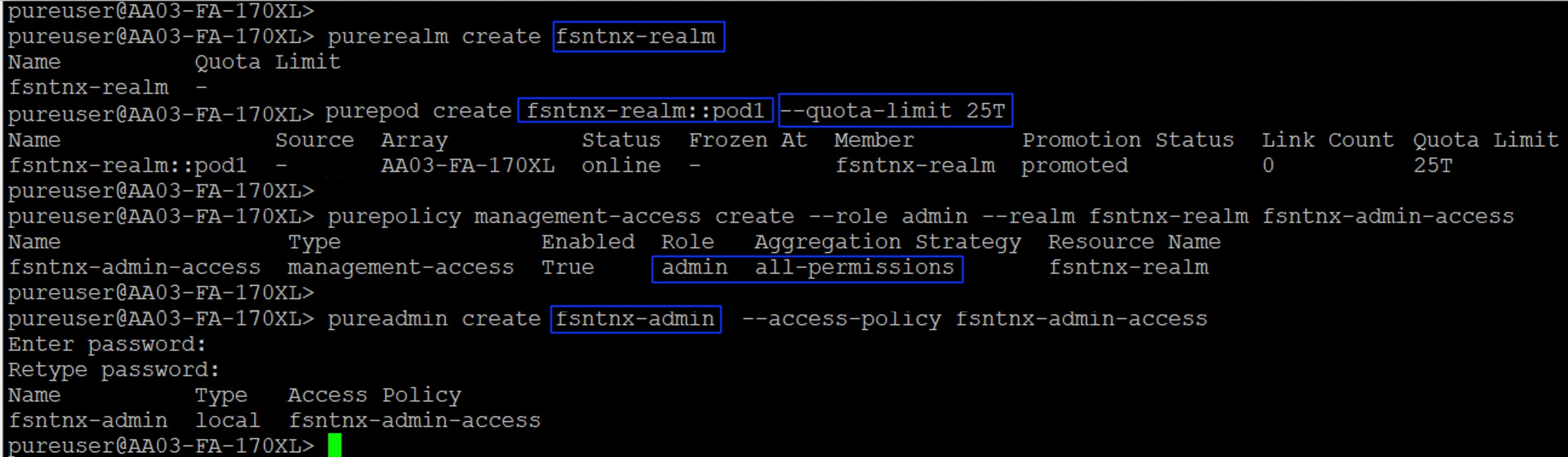
Step 1. ssh to the Pure FlashArray//Xl170 using its management ip and pureuser credentials. Run the following scripts for creating Realm+Pod combinations for each deployment type:
##For the greenfield deployment type
purerealm create fsntnx-realm
purepod create fsntnx-realm::pod1 --quota-limit 25T
purepolicy management-access create --role admin --realm fsntnx-realm fsntnx-admin-access
pureadmin create fsntnx-admin --access-policy fsntnx-admin-access
## Create Realm and Pods for the brownfield deployment type, by following the above steps.
The following screenshot shows the configuration of Ream+Pod combination for greenfield deployment type:
Procedure 3. Claim Pure Storage FlashArray//XL170 into Intersight
Note: This procedure assumes that Cisco Intersight Assist is already hosted and claimed into the Intersight.
Step 1. To claim the Pure Storage FlashArray into Intersight, log into Cisco Intersight using your login credentials. From the drop-down list select System.
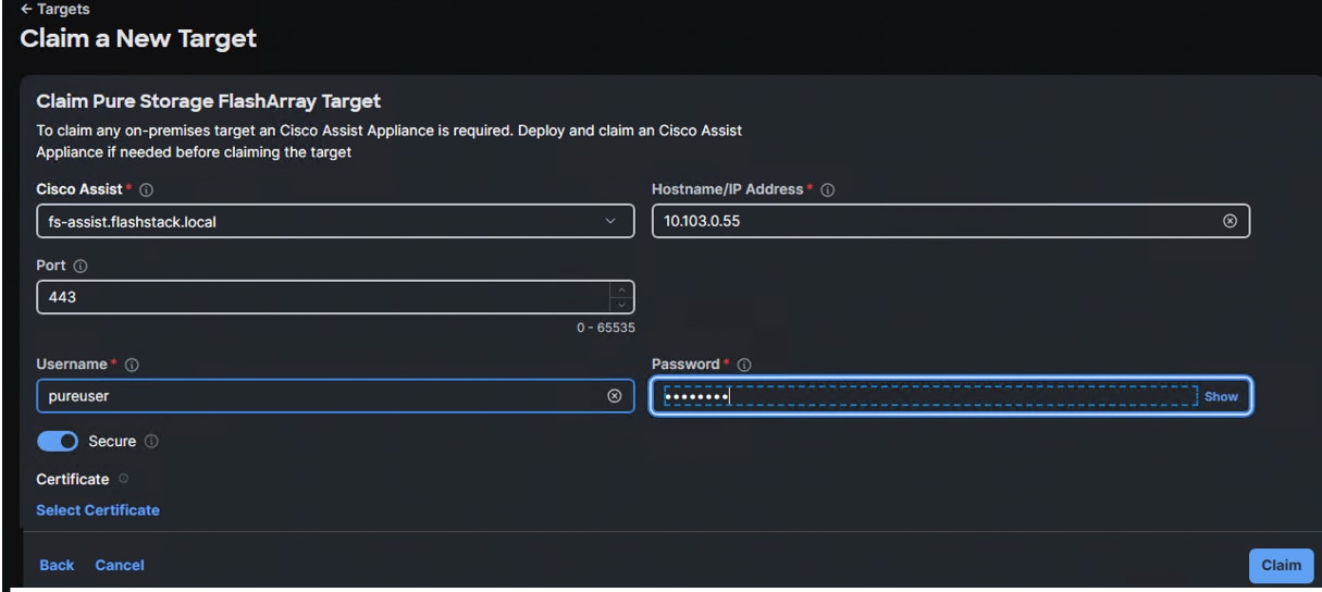
Step 2. Under Admin, select Target and click Claim a New Target. Under Categories, select Storage, click Pure Storage FlashArray and then click Start.
Step 3. Select the Cisco Assist name which is already deployed and configured. Provide the Pure Storage FlashArray management IP address, username, and password details and click Claim.
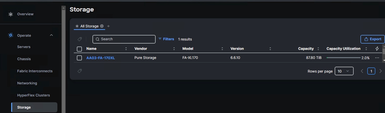
Step 4. When the storage is successfully claimed, go to select Infrastructure Services. Under Operate, click Storage. You will see the newly claimed Pure Storage FlashArray; browse through it to view the inventory details.
Cisco Intersight Configuration
The procedures in this chapter describe how to configure a Cisco UCS domain for use in a FlashStack environment. A Cisco UCS domain is defined as a pair for Cisco UCS FIs and all Cisco UCS B-Series, Cisco UCS X-Series and Cisco UCS C-Series servers connected to it. All the servers that are intended to be used as NCI Compute cluster nodes, must be connected and managed through Cisco Intersight IMM mode.
Note: This deployment guide assumes an Intersight account is already created, configured with required licenses and ready to use. A dedicated Resource Group and Organization will be created for managing the Nutanix servers used for this validation.
Note: This deployment guide assumes that the initial day-0 configuration of Fabric Interconnects is already done, updated with latest available firmware. Minimum supported FI firmware is 4.3(4.240066). See the Cisco UCS Fabric Interconnect Initialization Guide for the initial configuration.
Fabric Interconnect Domain Profile and Policies
This section contains the procedures to claim the FIs to Intersight account, create fabric interconnect domain profiles for each kind of deployment.
Procedure 1. Claim Fabric Interconnect into Intersight
Step 1. Log into your Intersight account with your credentials. Go to System > Targets and click Claim a New Target option.
Step 2. Select Cisco UCS Domain (Intersight Managed) option and click Start.
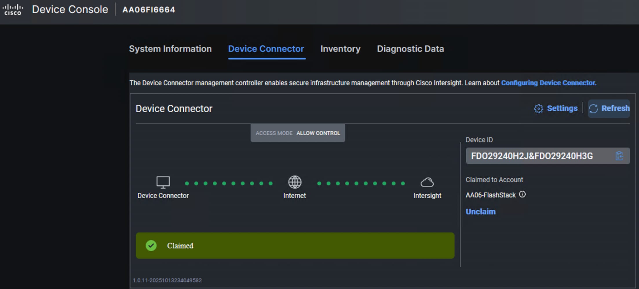
Step 3. Retrieve the Device ID and Claim Code for the Fabric Interconnect from its web console and enter the details and click Claim. The FIs will be claimed into your Default Resource Group of your Intersight account. The Custom Resource Groups (RGs) and Organizations can be created later and add the FIs to the custom Resource Groups.
Procedure 2. Upgrade Server Firmware
Step 1. Upgrade the firmware of the servers to the supported version in Cisco Intersight ahead of the Nutanix cluster deployment is recommended. Doing so can avoid any firmware upgrade failures from causing a Nutanix cluster deployment failure. See the Cisco UCS Nutanix Compatibility for supported firmware for each server type.
Procedure 3. Create Organization and Resource Groups
It is recommended to create dedicated Organizations and custom Resource Groups for managing Nutanix Cluster nodes. This approach simplifies management and enhances the security of server access. Follow these steps to create new Organization and Resource Group and add FI to the newly created Resource Group.
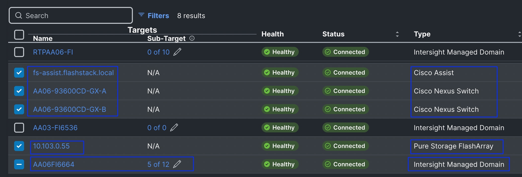
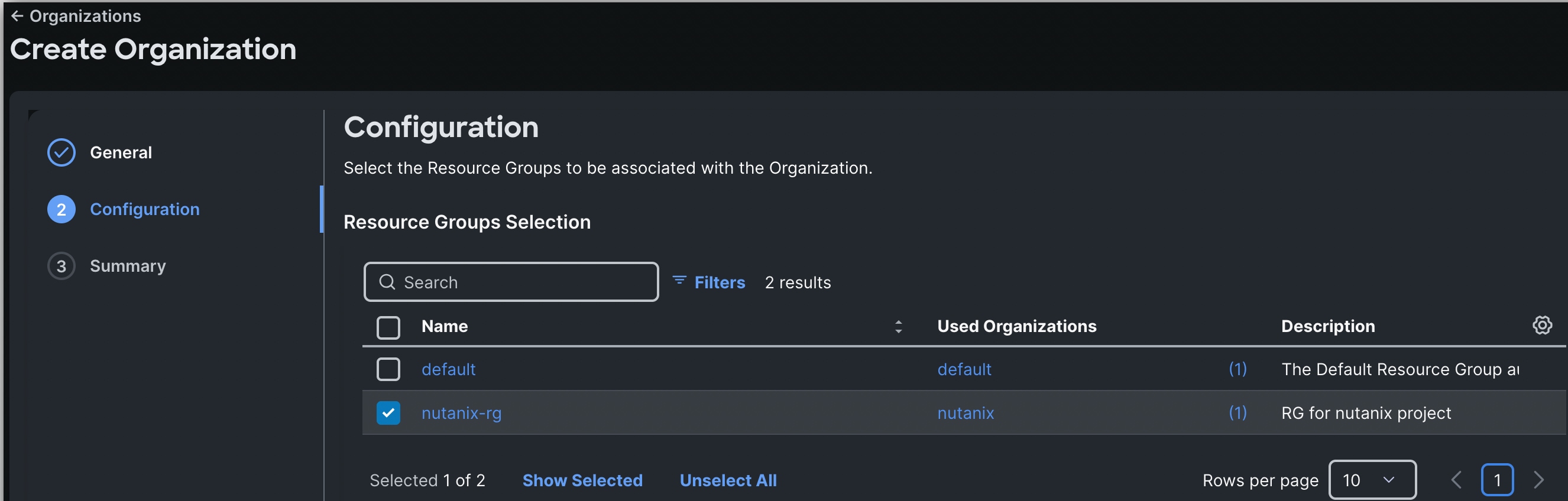
Step 1. Log into the Intersight portal, select System > Resource Groups > click Create Resource group. Provide the name as nutanix-rg and set resources as Custom. Select the 6664 FI and click the Pen symbol. Select all the servers that are going to be part of the Nutanix cluster. Along with the FIs, select all the remaining hardware components like Nexus switches, FlashArray and Intersight Assist and so on that are going to be part of your Nutanix Cluster as shown below. The following screenshot shows 5 out 12 servers along with other hardware components like Switches, Pure Storage and Intersight Assist. Once selected required components, click Create.
Step 2. Go to System > Organizations and click Create Organization. Provide a name as Nutanix and click Next. Select the nutanix-rg created in the above step and click Next. Review the summary and click Create.
Procedure 4. Create Fabric Interconnect Domain Profile and Policies for greenfield deployment (FI6664)
As discussed in the previous sections, Cisco UCS 6th generation 6664 Fabric Interconnects are used for the greenfield deployment. Follow this procedure for creating a UCS domain profile for 6664 FIs. For this greenfield deployment validation, a dedicated Intersight account “AA06-FlashStack” is created and claimed the 6664 FIs into this account under the default Organization.
Step 1. Log into the Intersight portal, select Configure > Profiles then select UCS Domain Profiles > Create Domain Profile.
Step 2. Set the Organization to default and provide a name to the FI domain profile (AA06FI6664-UCSDomain/) and click Next. Click Assign Later to assign this domain profile to a FI later. Click Next.
Step 3. Click Next to go to VLAN & VSAN Configuration.
Step 4. Under VLAN & VSAN Configuration > VLAN Configuration, click Select Policy then click Create New.
Step 5. On the Create VLAN page, enter a name (AA06-FI6664-VLANs) and click Next. To add a VLAN, click Add VLANs.
Step 6. For the Prefix, enter the VLAN name as OOB-Mgmt-VLAN. For the VLAN ID, enter the VLAN ID 1060. Leave Auto Allow on Uplinks enabled and Enable VLAN Sharing disabled.
Step 7. Under Multicast Policy, click Select Policy and select Create New to create a Multicast policy.
Step 8. On the Create Multicast Policy page, enter the name (AA06-FI-MultiCast) of the policy and click Next to go to Policy Details. Leave the Snooping State and Source IP Proxy state checked/enabled and click Create. Select the newly created Multicast policy.
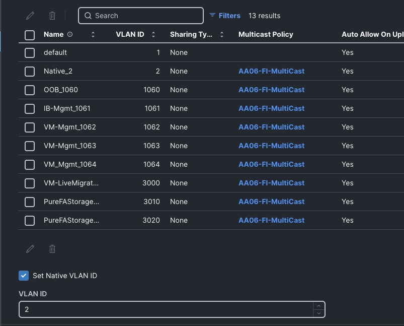
Step 9. Repeat steps 6 through 8 to add all the required VLANs to the VLAN policy.
Step 10. After adding all the VLANs, click Set Native VLAN ID and enter the native VLANs (for example 2) and click Create. The VLANs used for this solution are shown below:
Step 11. Select the newly created VLAN policy for both Fabric Interconnects A and B. Click Next to go to the Port configuration.
Step 12. Create a new Ports Configuration Policy for each Fabric Interconnect. Provide a name (AA06FI6664-A-PortConf) and select the UCS-FI-6664 from Fabric Interconnect model drop-down list. Click Next and go to Port Roles.
Step 13. Select the appropriate ports, where the X-series M7 and C-series M7 servers are connected, Click Configure to set them as server ports by setting Role to Server.
Step 14. Click on the Port Channels tab and click Create Port Channel. Select Port 63 and 64 for FI6664, set Role to Ethernet Uplink Port Channel, set 100 for Port Channel ID and admin speed to 100Gbps and FEC to Cl91. Under Link Control, create a new link control policy with settings described in the following table. Once created, click Save to complete the Port policy configuration.
Step 15. Repeat steps 12 to 14 to create another port configuration policy (AA06FI6664-B-PortConf) for Fabric Interconnect B with Ethernet Uplink Port Channel ID set to 200. Select the corresponding Port configuration policies created for FI-A and FI-B.
| Policy Name |
Setting Name |
| AA06-FI-LinkControll |
UDLD Admin State: True UDLD mode: Normal |
Step 16. Once two Port configurations are selected for FI-A and B, click Next to go to the UCS Domain Configuration page. The following tables list the management and network related polices created and used for this validation. Create NTP, Network Connectivity and QoS policies as described below and complete the UCS Domain Profile creation for 6664 Fabric Interconnects used in greenfield deployment option.
| Policy Name |
Setting Name |
| AA06-FI-OCP-NTP |
Enable ntp: on Server list: 172.20.10.11,172.20.10.12,172.20.10.13 Timezone: America/New_York |
Table 12. Network Connectivity Policy
| Policy Name |
Setting Name |
| AA06-FS-OCP-NWPolicy |
Proffered IPV4 DNS Server: 10.106.1.21 Alternate IPV4 DNS Server: 10.106.1.22 |
| Policy Name |
Setting Name |
| AA06-FS-OCP-SystemQoS |
Best Effort: Enable Weight: 5 MTU: 9216 |
Step 17. Select the newly created UCS domain policy using the above steps and assign it to Fabric Interconnects used for the greenfield deployment. Ensure the policy is assigned to the FIs cleanly, and Status of the UCS domain policy turns to OK. After the Domain profile is deployed, all modular chassis, the blades in the chassis and the rackmount servers will be discovered. Once all the chassis, blades and rackmounts have finished discovery, the next steps can be completed.
Note: For brownfield deployments, it is assumed that the Fabric Interconnects are already configured with required Domain Profiles to support the existing infrastructure. Therefore, Domain Profile configuration steps are not included in the following procedures. Ensure all the required VLANs for management, storage and guest traffic are defined in the Domain Profiles.
Create Pools, Policies for LAN Connectivity Policy
As discussed in the section Considerations and Recommendations for FlashStack with Nutanix, It is required to create a separate pair of vNIC interfaces for each node to segregate different types of traffics. The required vNICs pairs can be configured during the cluster deployment using Foundation Central. However, Cisco UCS LAN Connectivity Policy (LCP) can be used to define the required vNICs with advanced configuration options including vNIC placement, VLAN ID, PCI order and so on. If you do not wish you create the LAN connectivity policy manually, skip creation of LAN connectivity policy steps and ensure to define the vNIC pairs for each type of traffic at the time of Nutanix cluster deployment.
Note: The MAC address pool and IP Pools are required to be created manually, even if you chose to define the vNIC pairs during the Nutanix cluster deployment using Foundation Central. The UUID pool is required for Cisco UCS B-Series and Cisco UCS X-series and optional for Cisco UCS C-series servers. The remaining policies, such as Ethernet Network Group, Ethernet Network Control, Ethernet QoS and Ethernet Adapater policies, are required to be created manually only when you choose to configure vNICs using LCP. If not, these policies are not required to be created manually.
This section provides detailed steps for creating required pools, policies and LAN connectivity policy for Nutanix node networking. Architectural details on Nutanix node are discussed in NCI Compute Cluster Node Networking section. It is recommended to use LAN connectivity policy for defining the vNICs with advanced option instead of defining them during the Nutanix cluster deployment. Follow the below steps for creating required pools and policies for Nutanix node networking.
Procedure 1. LAN Connectivity Policy, Pools and Policies Used for NCI Cluster Compute Node
Before creating the LAN connectivity policy, create the required pools and policies and then LAN connectivity policy used by the Nutanix deployment.
Step 1. Create a MAC pool using details provided in the following table. For every pair of vNICs, Nutanix deployment allows you to create a new MAC pool. For instance, you can create 3 different MAC pools one for two vNICs that carry AHV and CVM management traffic, second one for vNICs that carry storage traffic and third one for vNIC that carry guest traffic. For this validation, only one common MAC pool is created for all the vNIC pairs.
| Policy Description |
Setting Name/Value |
| MAC pool for all vNIC pairs |
Name: ntnx-mac-pool-common |
Step 2. Create a UUID Pool using the details provided in Table 15.
| Policy Description |
Setting Name/Value |
| UUID pool for Nutanix nodes |
Name: ntnx-uuid-pool |
Step 3. Create IP Pool for Out-Of-Band (OOB) management of the servers using the details provided in Table 16.
| Policy Description |
Setting Name/Value |
| IP pool for OOB management of Nutanix nodes |
Name: ntnx-oob-ip-pool |
Step 4. Create the required Network Group, Network Control, Ethernet QoS and Ethernet adapter policies as detailed in the following tables. The LAN Connectivity Policy uses these policies.
Table 17. Ethernet Network Group Policies used by the vNICs
| Policy Description |
Setting Name/Value |
| Ethernet Network group policy will have the VLANs used by the vNIC |
Name: ntnx-infra-ethnwgrp |
Table 18. Ethernet Network Control Policy
| Policy Description |
Setting Name/Value |
| Network control policy defines how server Virtual NICs (vNICs) interact with the upstream network. |
Name: ntnx-eth-nwdontrol |
| Policy Description |
Setting Name/Value |
| Prioritize network traffic within the Unified Computing System by assigning traffic to system classes (like Best Effort, Platinum) and controlling parameters such as rate, burst, and MTU, ensuring critical applications get required bandwidth |
Name: ntnx-QoS |
Table 20. Ethernet Adapter Policy
| Policy Description |
Setting Name/Value |
| defines host-side behavior for network adapters, controlling settings like transmit/receive queues, interrupt handling (coalescing, RSS), and Performance features |
Name: ntnx-eth-adapter-policy |
Step 5. Create a LAN Connectivity policy by leveraging the above policies. Go to Configure > policies. Click Create Policy. Search for LAN Conn. Select the LAN Connectivity radio button and select Start.
Step 6. Select nutanix for organization, provide a name (ntnx-single-vic-lan-conn), and set UCS Server (FI Attached) to Target Platform. Click Next.
Step 7. Click Add to a vNIC, provide a name (ntnx-infra-1-A) to the vNIC. Select the ntnx-mac-pool-common created in the previous step for the MAC Pool. Click Advanced for Placement. Provide MLOM for the Slot ID. Set 0 for PCI Link and select A from the Switch ID drop-down list and set 0 for PCI Order. Disable the Failover. Select the ntnx-infra-ethnwgrp policy for Ethernet network group policy, ntnx-eth-nwcontrol for network control policy, ntnx-QoS for QoS policy, and ntnx-eth-adapter-policy for adapter policy. Complete the ntnx-infra-1-A vNIC creation by clicking Finish.
Step 8. Repeat step 7 to create the remaining vNICs with settings detailed in Table 4. The following screenshot shows the vNICs used for both deployment types:
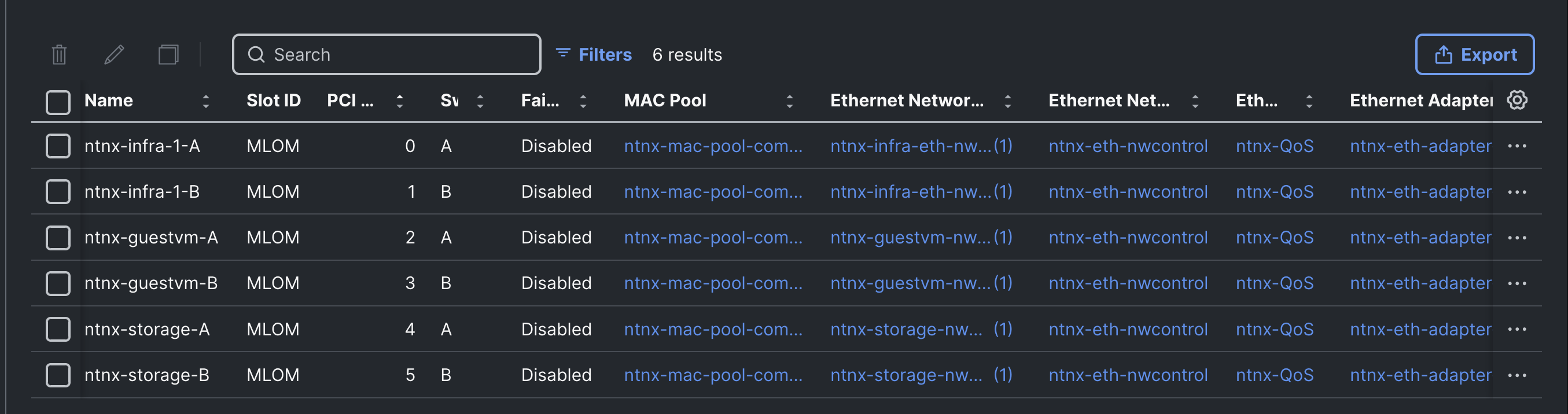
Note: See the FlashStack with Nutanix Installation Field Guide for configuring LAN connectivity policies for servers having more than one Cisco UCS VIC.
Procedure 2. Generate Intersight API Key
This procedure enables you to generate an Intersight API Key used by Foundation Central for communicating with Cisco Intersight.
Step 1. Log into Cisco Intersight. Go to Setting > Keys. Click Generate API Key with Schema 3. Provide a Description for the API key and set the expiry date for the API Key. Click Generate. Write down the API key and download secret key. This API Key along with Secret Key needs to be added in the Foundation Central.
Select Nutanix Installation Method
For this validation, it is assumed that you have no Nutanix installation base and must begin from nothing starting with the Foundation Central Appliance (FCA) VM installation on a workstation. Installing FCA on a workstation and provisioning Nutanix cluster is the preferred method of deployment especially for those who don’t have a Nutanix presence in their datacenters.
For more information on the various installation options for Nutanix environments, see the Cisco FlashStack with Nutanix Installation Field Guide.
For instructions on installing a Foundation Central VM on a workstation, go to Preparing the Workstation. Deploy FCA VM on the workstation by following the link. When the FCA VM is deployed, see Setting up the Foundation Central Appliance to configure the network settings, proxy, firewalls and so on. Once the setup is successful, you can launch the Foundation Central Appliance VM using the browser using the IP address <https://FCA_IP:9440> as shown below. Log into the FCA with “admin” user set during the post deployment configuration.
Note: The Foundation Central (FC) Appliance VM cannot be used for expanding an existing Nutanix cluster. Prism Central must be utilized for Nutanix cluster expansion activities. For this validation process, The Foundation Central Appliance VM is used initially to provision the new Nutanix cluster. After the cluster has been provisioned, Prism Central will be deployed on the newly created cluster. Prism Central will then be used for any subsequent cluster expansion tasks.
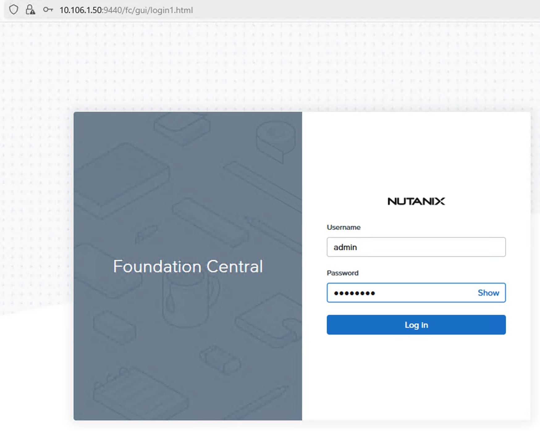
Install NCI Compute Cluster on FlashStack
This section provides detailed steps for deploying Nutanix Cluster on FlashStack using Foundation Central Appliance VM. If you are using Foundation Central via Prism Central for Nutanix Cluster deployment, then all configuration and deployment steps are the same as using the FC Appliance VM, except the version running within Prism Central cannot have the AOS and AHV images uploaded to it, therefore an external anonymous HTTP server must be used to host the installation files. Optionally, you can use the Cisco IMM transition tool which comes with default HTTP server for software repository which can be used for uploading the Nutanix installation files.
Procedure 1. Download Nutanix bundles from Nutanix portal and upload to FCA
Step 1. Download the supported Nutanix AOS image and its associated metadata file, and AHV installer files from Nutanix portal. These files must be accessed by an HTTP server for the cluster deployment. These files can be uploaded to the FC appliance VM using a series of API calls as shown below. Finally, note down the complete url of each individual file.
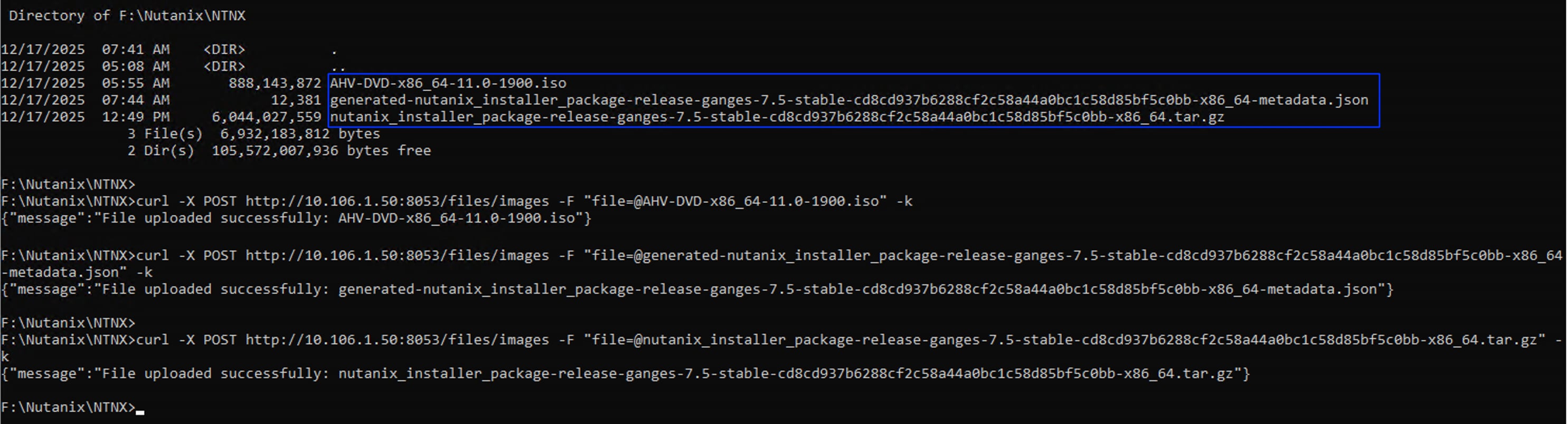
curl -X POST http://10.106.1.50:8053/files/images -F "file=@AHV-DVD-x86_64-11.0-1900.iso" -k
curl -X POST http://10.106.1.50:8053/files/images -F "file=@generated-nutanix_installer_package-release-ganges-7.5-stable-cd8cd937b6288cf2c58a44a0bc1c58d85bf5c0bb-x86_64-metadata.json" -k
curl -X POST http://10.106.1.50:8053/files/images -F "file=@nutanix_installer_package-release-ganges-7.5-stable-cd8cd937b6288cf2c58a44a0bc1c58d85bf5c0bb-x86_64.tar.gz" -k
curl -X GET http://10.106.1.50:8053/files/images -k
### note down the complete urls of each individual file
http://10.106.1.50:8053/files/images/AHV-DVD-x86_64-11.0-1900.iso
http://10.106.1.50:8053/files/images/generated-nutanix_installer_package-release-ganges-7.5-stable-cd8cd937b6288cf2c58a44a0bc1c58d85bf5c0bb-x86_64-metadata.json
http://10.106.1.50:8053/files/images/nutanix_installer_package-release-ganges-7.5-stable-cd8cd937b6288cf2c58a44a0bc1c58d85bf5c0bb-x86_64.tar.gz
Procedure 2. Configure and Connect Hardware Provider and Onboard the Servers
Follow this procedure to configure Cisco Intersight and onboard the servers. Go to Table 6 for Nutanix cluster name and other networking details which will be referred in this section for deploying the clusters.
Step 1. Log into the FC appliance VM and click Settings > Connect Hardware Provider. Provide the Connection Name as Intersight and select the Cisco Intersight from Hardware provider drop-down list. Set Saas for the Intersight Deployment Type. Provide the API Key and Secret key for the Cisco Intersight SaaS being used. Only one connection to Cisco Intersight hardware provider is allowed at one time.
Step 2. Click API Keys Management and click Generate API Key. Provide a name to API key and click Generate API Key.
Step 3. Click Nodes > Manually Onboarded tab and click Onboard Nodes. Ensure Cisco Intersight is selected as Hardware provider and Node Management mode is set to IMM. Click Next. Select the required nodes that you want to use for deploying Nutanix Cluster. Click Onboard Nodes.
Step 4. Select the onboarded nodes to be used in the new Nutanix cluster and then click Create Cluster as shown in the following screenshot.
Note: For each deployment types, the cluster is initially created with five nodes, and then the cluster is expanded with the sixth node.
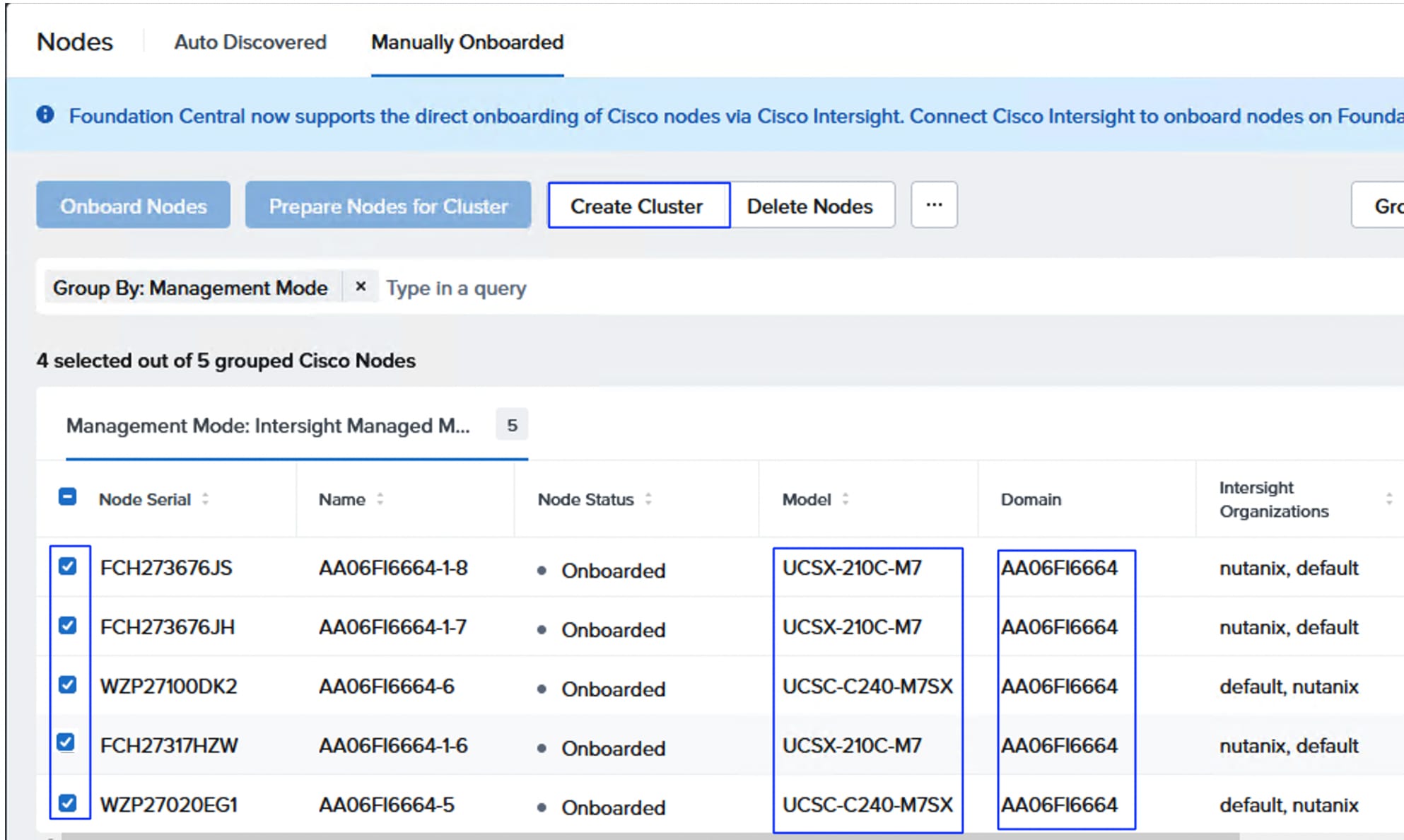
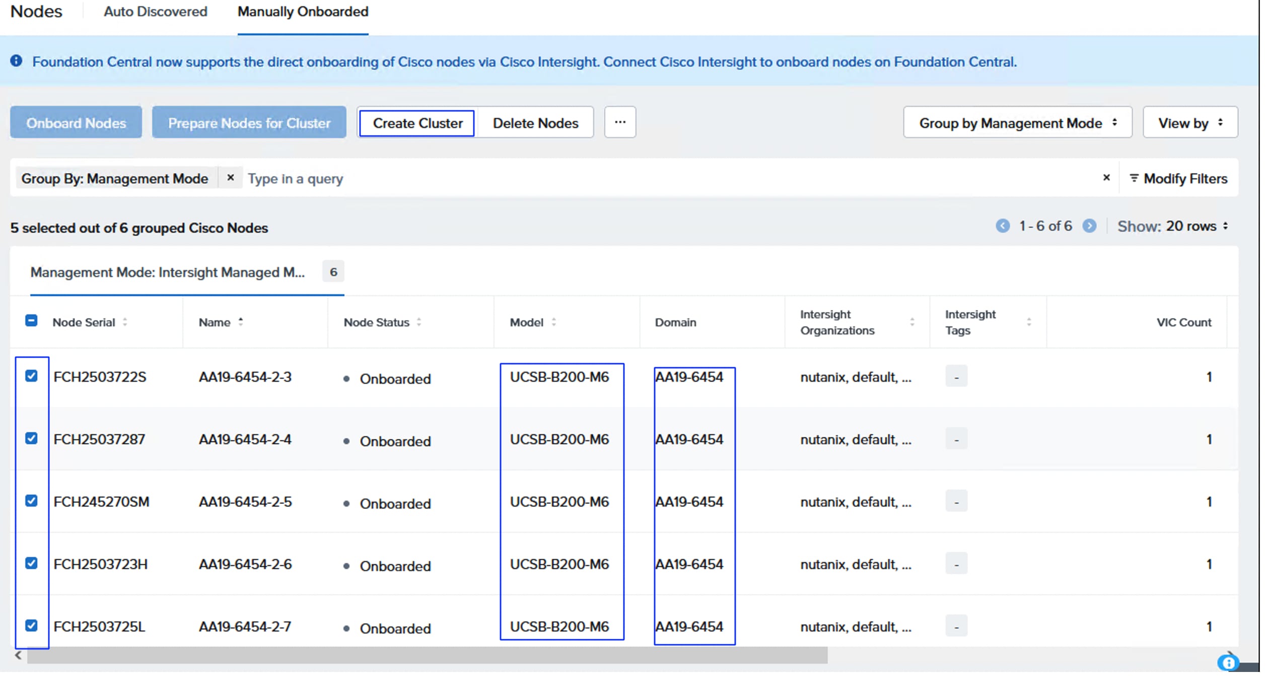
Step 5. In Cluster Details, provide Cluster name as fs-ntnx (fs-m6-ntnx for brownfield deployment). Select cluster to Compute Cluster and select the Organization (nutanix) and then click Next.
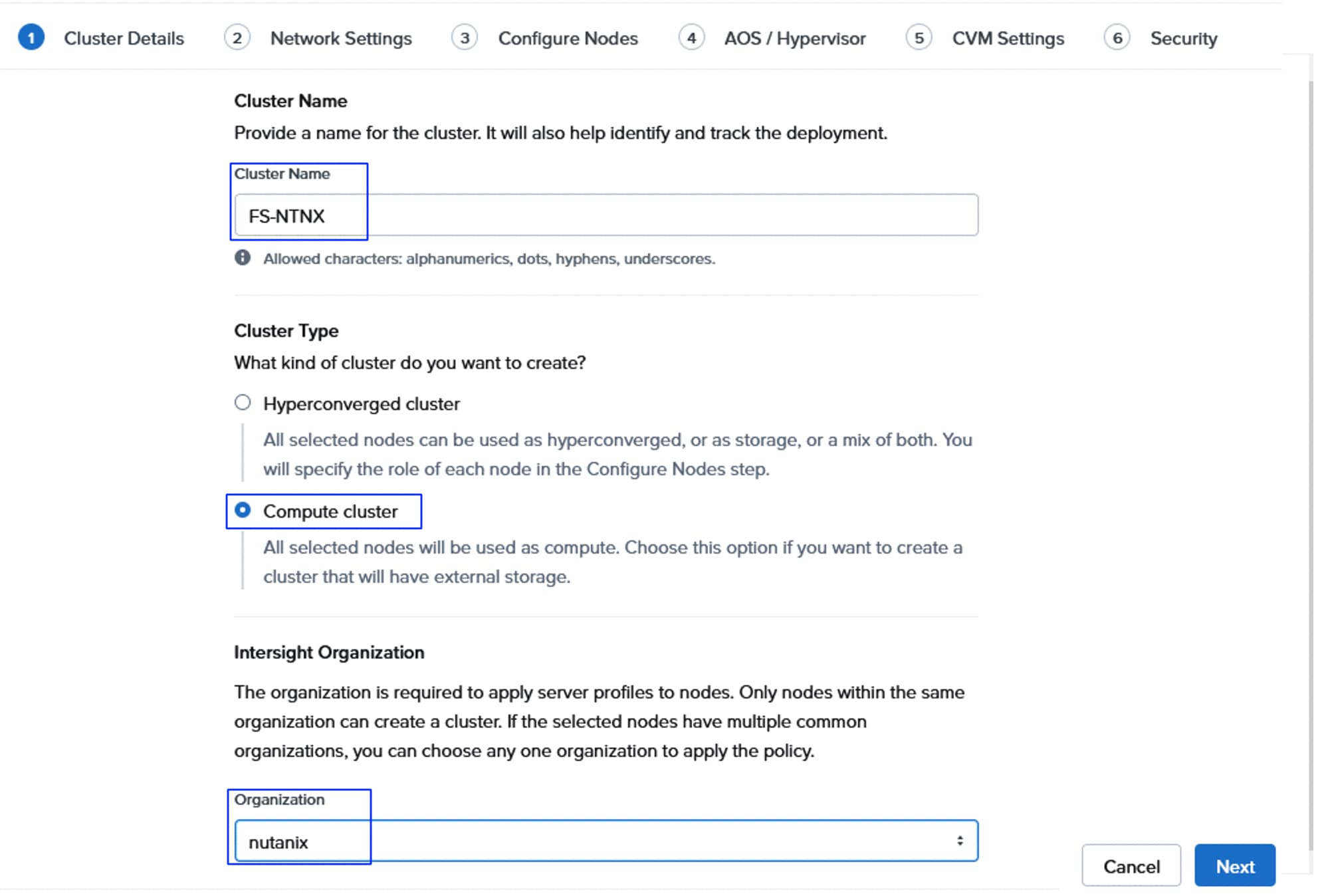
Note: When installing, your API key must have at least “Server Administrator” privileges in the org, and “Read-only” privileges to the entire domain via their assigned role, plus the hardware resources must also be associated with this organization using their resource group.
Step 6. Under Networking settings, provide corresponding Gateway IP and select Netmask. Provide the virtual Cluster IP for the cluster. Under vNIC configuration, click Create. See Tables 15,16 and 17 and keep the required information ready for the next steps. On the Infrastructure vNIC Pair window, select the MAC pool (ntnx-mac-pool-A), 1061 as VLAN for both host/CVM VLAN and for other vNICs VLAN. Set MTU as 9000 and click Create. As discussed earlier, LAN connectivity policy will be used for defining the additional vNIC pairs. Select Additional vNIC Pairs, click the Use LAN connectivity policy and select the policy (ntnx-singlevic—lan-conn) from the drop-down list as shown below. Do not select the LACP option.
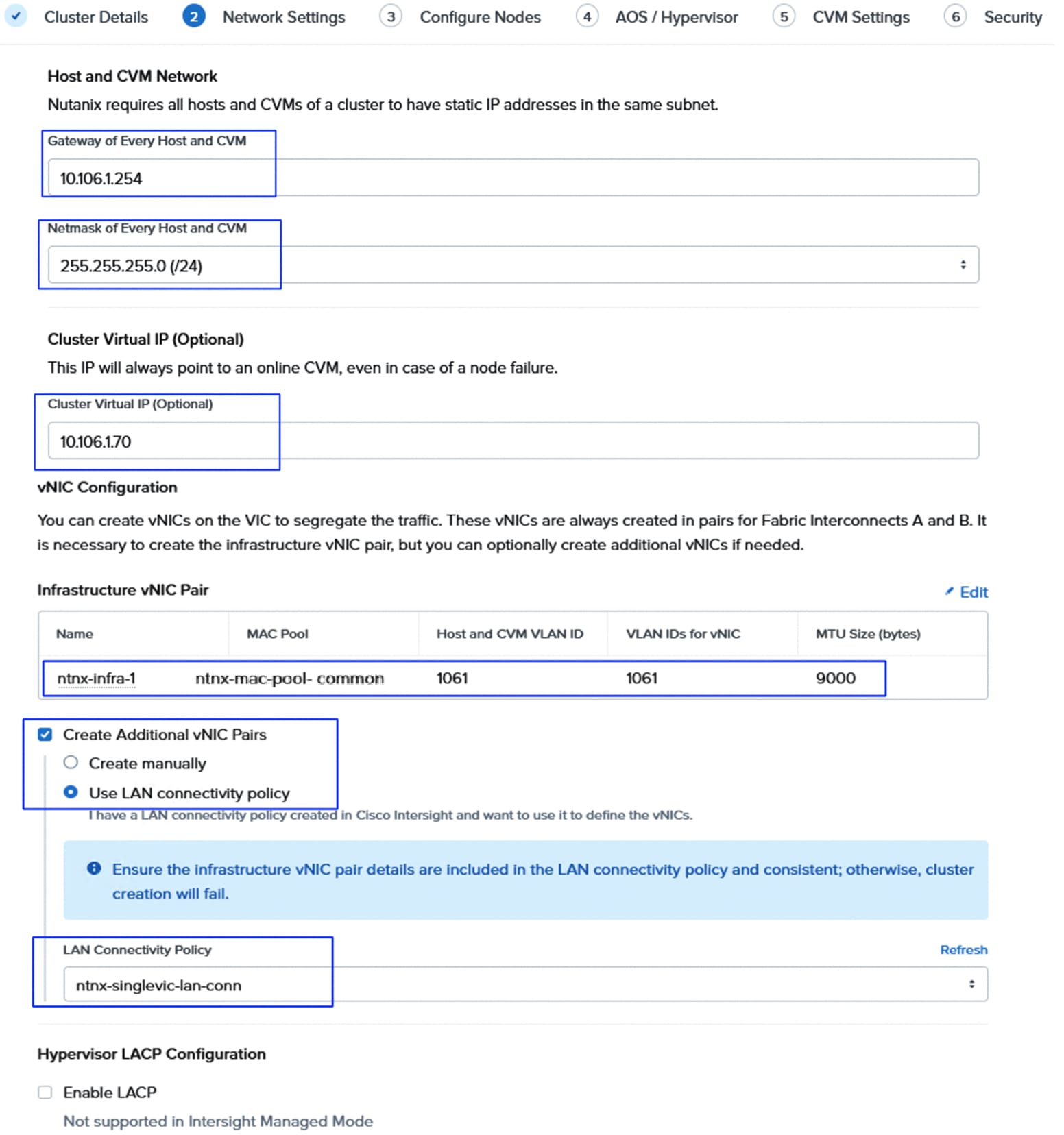
Note: When deploying servers with dual VIC cards, two pairs of “infrastructure” vNICs will be created with the same settings for both pairs.
Note: When not using the LAN Connectivity policy for the additional vNIC pairs, create at least one additional vNIC pair for NVMe/TCP storage traffic using the corresponding VLANs (3010 and 3020) and MTU as 9000. Additional vNIC pairs can be created for the other traffic types.
Step 7. From the same window, for IMC Access Configuration, select the Out-of-Band option and the Out-of-Band IP pool (ntnx-oob-ip-pool) and click Next.
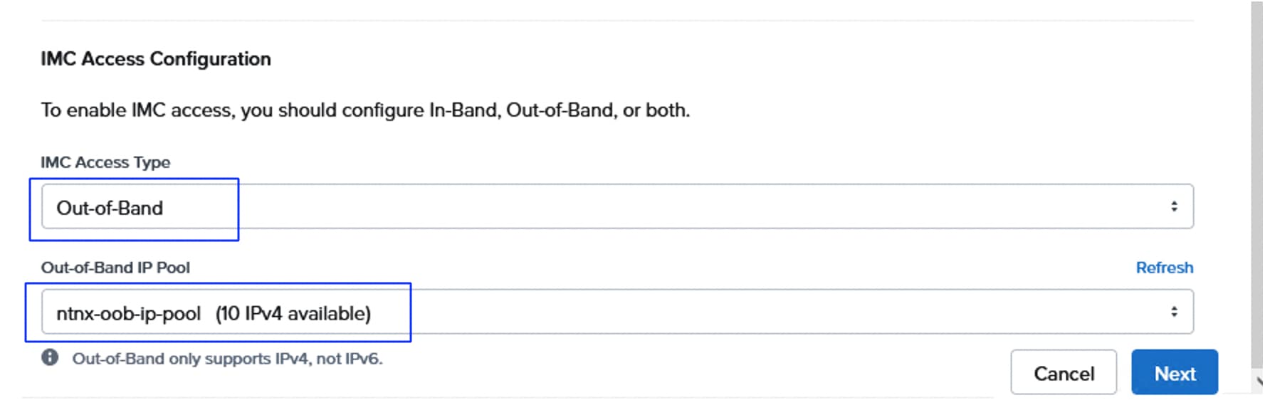
Step 8. On the Configure Nodes window, select the UUID policy (ntnx-uuid-policy) and enter the management IP addresses for all the AHV nodes and CVMs. Select appropriate Firmware Package for each server type. Click Next. See Table 3 for the supported firmware for the corresponding servers.
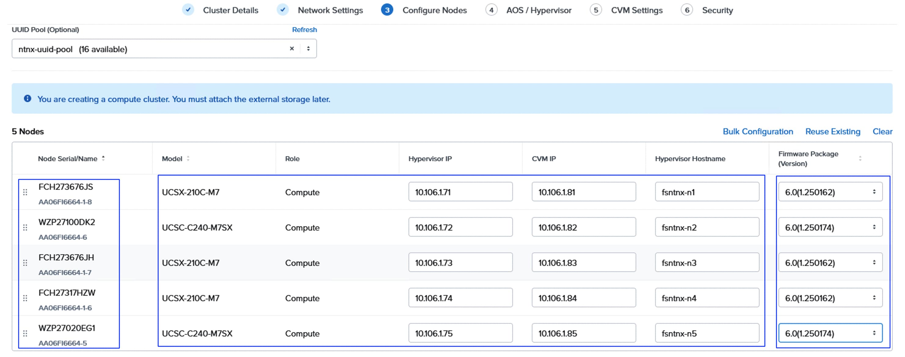
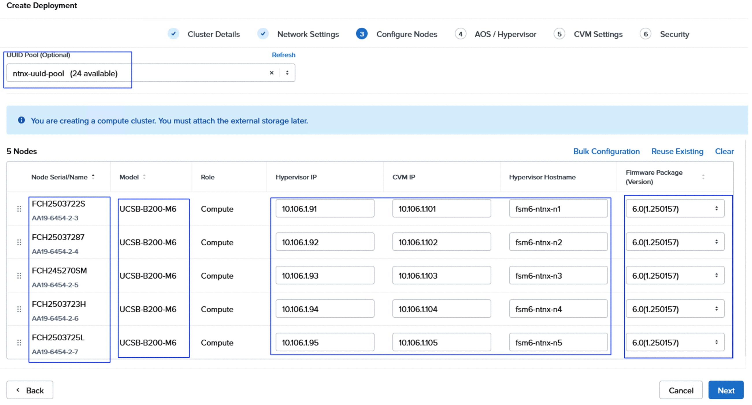
Step 9. Enter HTTP URLS for AOS Image, AOS metadata, and AHV images as noted in the previous section. Click Next.
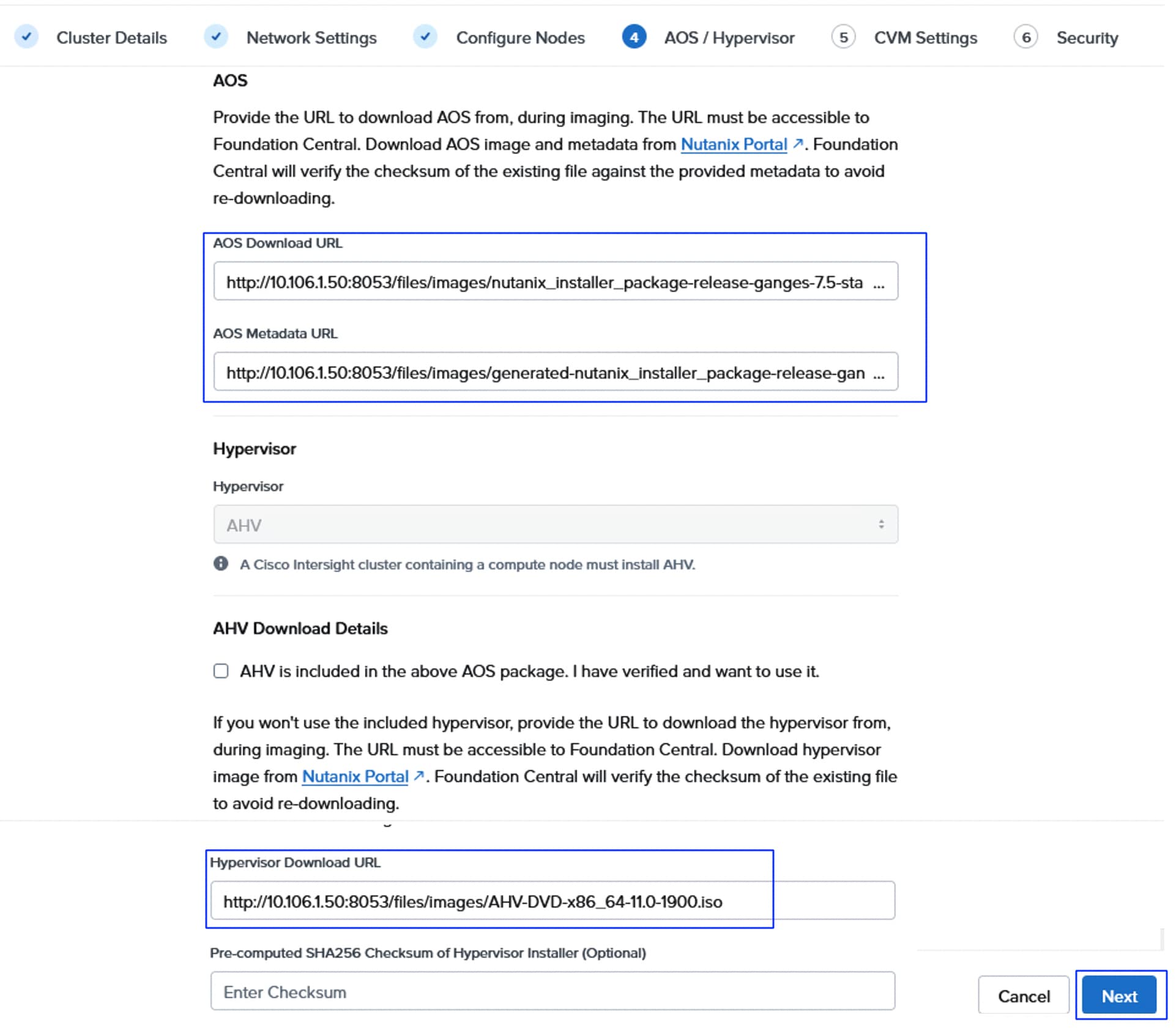
Step 10. From the CVM settings window, select the required Time zone and set NTP and DNS servers and click Next.
Step 11. From the security window, select the FC API key that was created in the previous sections. Click Create Deployment.
When using a custom LAN Connectivity Policy, a validation task will be run when clicking Create Deployment. If any problems exist, such as the default “infrastructure” vNIC pairs missing or their names misspelled, an alert message will pop up at this stage. If this happens, fix any errors present in the LAN Connectivity Policy in Cisco Intersight, then click Create Deployment again. Only the required “infrastructure” vNIC pairs are validated, and any additional vNIC pairs will be accepted as configured. If there are errors in the LAN Connectivity Policy for these additional vNIC pairs, such as invalid ordering or problems with the VLAN ID assignments, it will result in a failure later during the server profile assignment phase 1A of the deployment.
Note: The deployment can take about 60 to 90 minutes based on whether the firmware updates are included in the deployment.
Step 12. Once deployment completes successfully, click the Open Prism Element (PE) to launch the PE of the clusters.
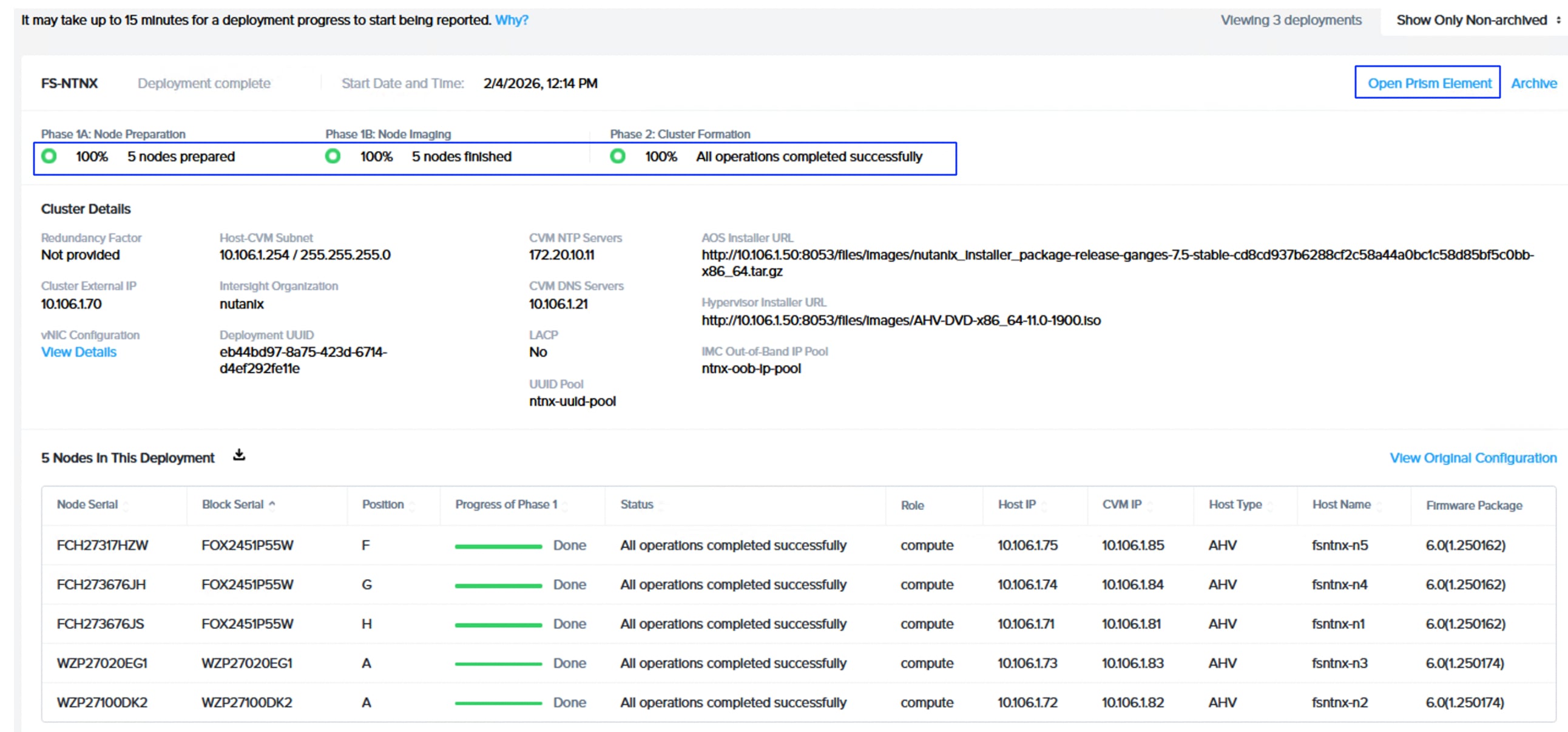
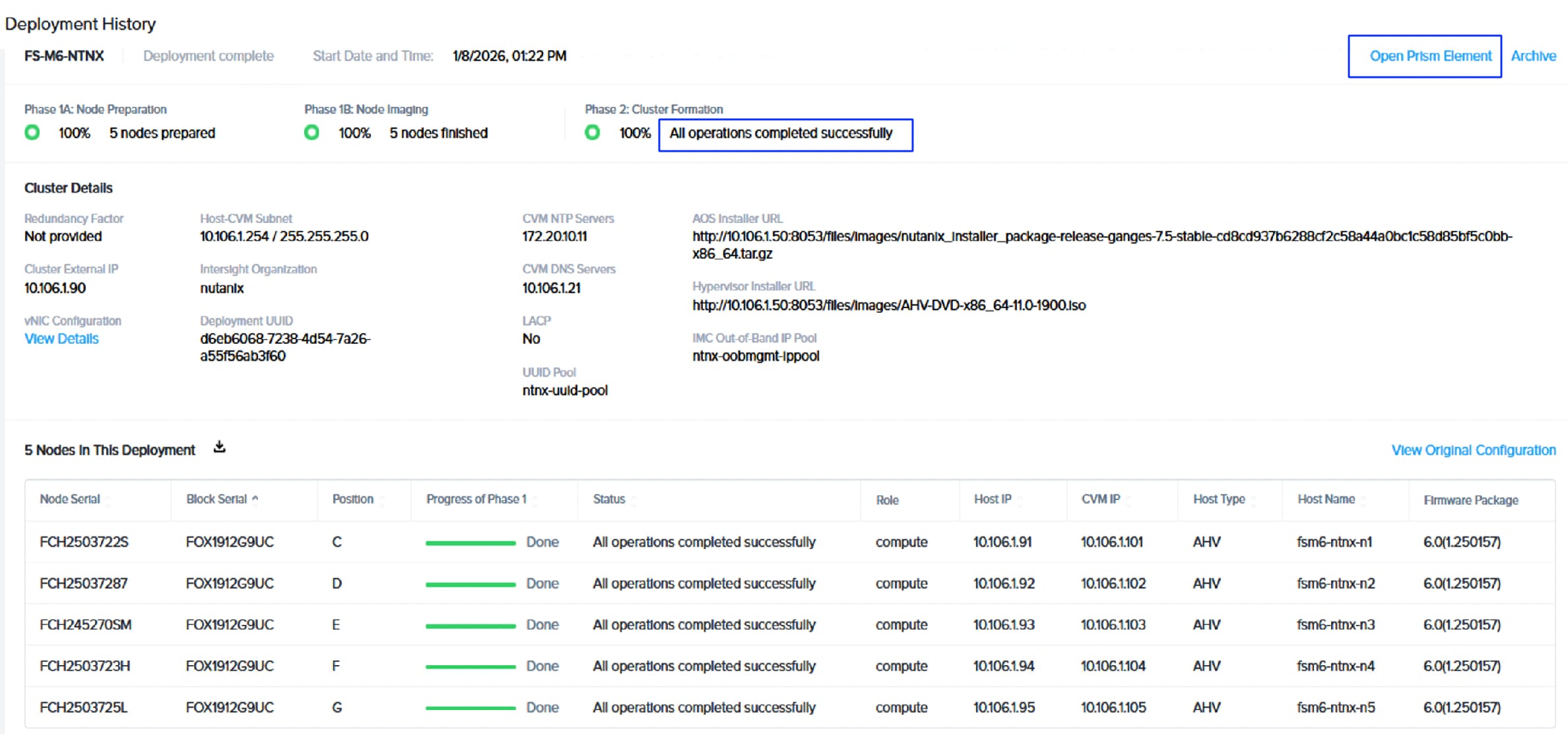
Configure External Storage Array Connectivity
Once the Nutanix cluster is deployed successfully, the external storage connectivity must be configured before creating any Virtual Machines on the cluster.
Procedure 1. Verify and modify the default virtual switch (if necessary)
It is recommended to ensure that only infrastructure vNICs (eth0 and eth1) are configured as uplinks for the default virtual switch vs0. If any other vNICs are configured as uplinks for vs0, then modify the switch vs0 and remove those vNICs.
Step 1. Launch the Prism Element by using a cluster virtual IP <https://virtualIP:9440> or click the Open Prism Element link as shown in the previous step. Log in with default credentials admin and nutanix/4u and change the default password on the first login. Provide admin, company details, and Accept the license agreements. Do not disable the Pulse and click Continue.
Step 2. Upon the successful login, the window Set up External Storage opens. Click I’ll do this later.
Step 3. Select Settings from the drop-down list and go to Network > Network Configuration > Virtual Switch. Click the pencil symbol of vs0. Leave the configuration method as Standard and click Next.
Step 4. Expand each host listed under Hosts box and ensure only eth0 and eth1 are selected. If any other vNICs are selected, remove them as uplinks from vs0. After repeating this process for each host, click Save.
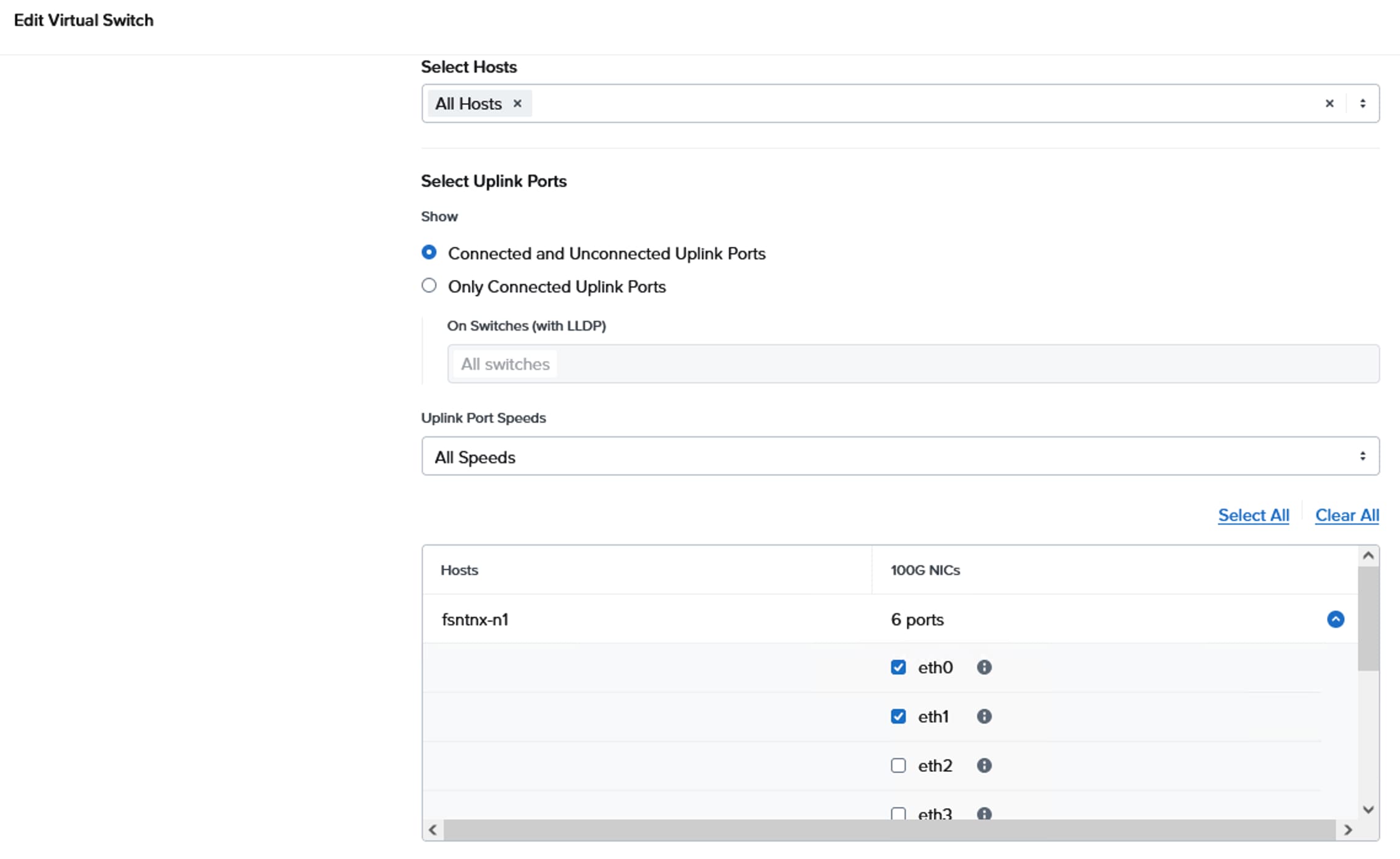
Step 5. Click Create VS to create a dedicated switch for storage connectivity. Provide a name as vs_storage and set MTU as 9000. Leave Standard Configuration method selected and click Next.
Step 6. Set the bond type to Active-Active with Mac pinning. Under the Hosts box, expand each host and select eth4 and eth5 storage interfaces as uplinks for the vs_storage vswitch. Hover the mouse on the i symbol. A window opens showing the details of each interface which helps us to identify the storage interfaces easily. Click Create when the correct vNICs are selected.
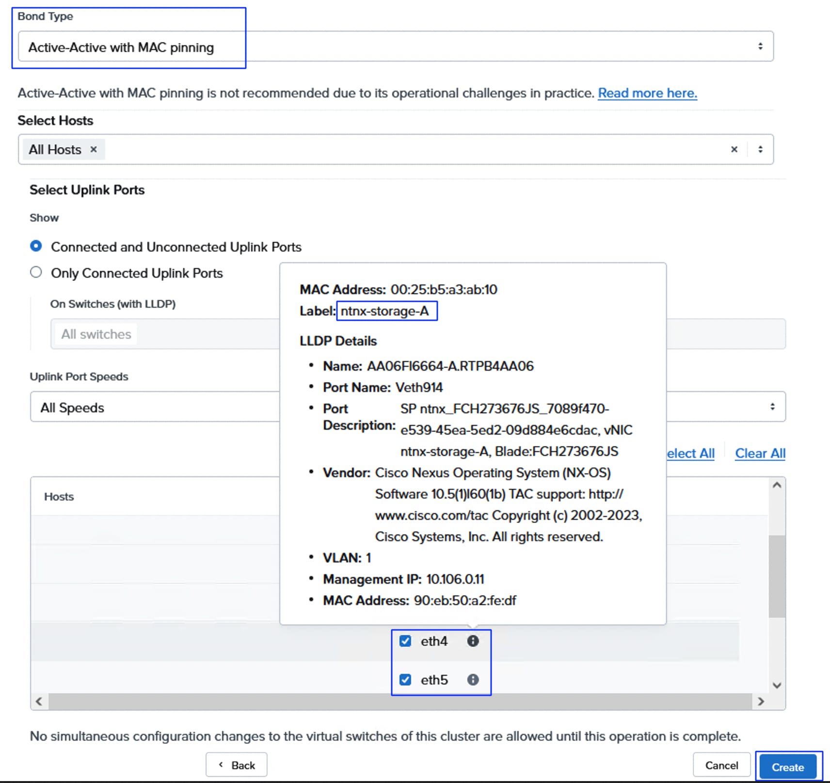
Note: A configuration job starts to create the virtual switch. Wait until the job has completed before moving to the next task.
Step 7. Two internal interfaces will be created, with one interface assigned to each storage VLAN. Each interface is associated with newly created virtual switch (vs_storage), and a pool of IP addresses is created for assignment to the hosts. Click Internal Interfaces > Create New Interfaces.
Step 8. Provide a name to the first interface as storage_vlan3010, enter VLAN 3010 for VLAN ID, select the vs_storage virtual switch for Virtual Switch. Click Create New IP Pool under IP Pool box. Provide a name to IP pool and enter netmask as 255.255.255.0 and provide an IP range. Ensure the IPs are in the same subnet as CT0.eth10 and CT1.eth10. Click Save from the IP Pool window then click Next. One IP address per host in the cluster will be assigned from this pool, so ensure the pool is large enough, plus room for growth.
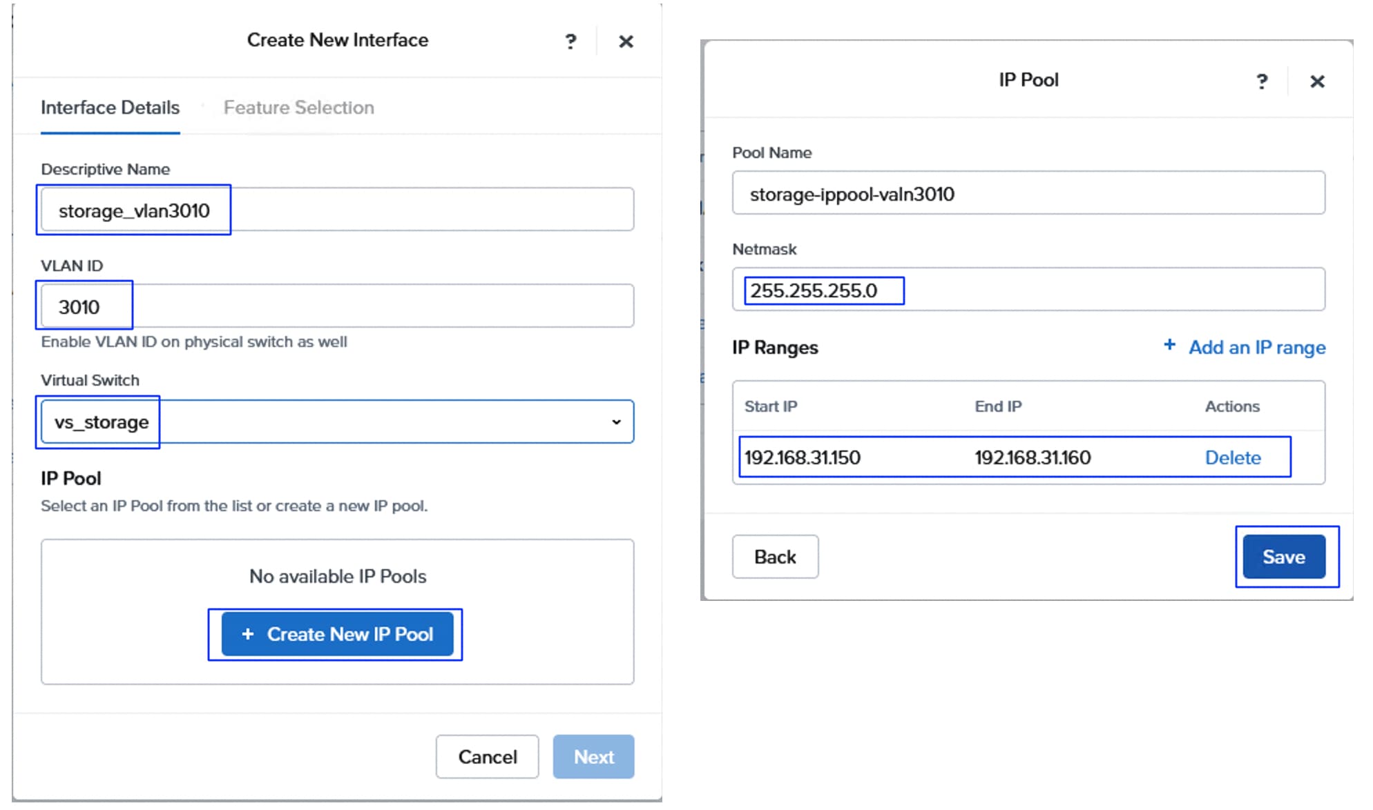
Step 9. Under the Feature selection tab, enable External Storage feature and set MTU 9000 and click Save. A window pops up and click Enable interface. No advanced settings or Gateway are required.
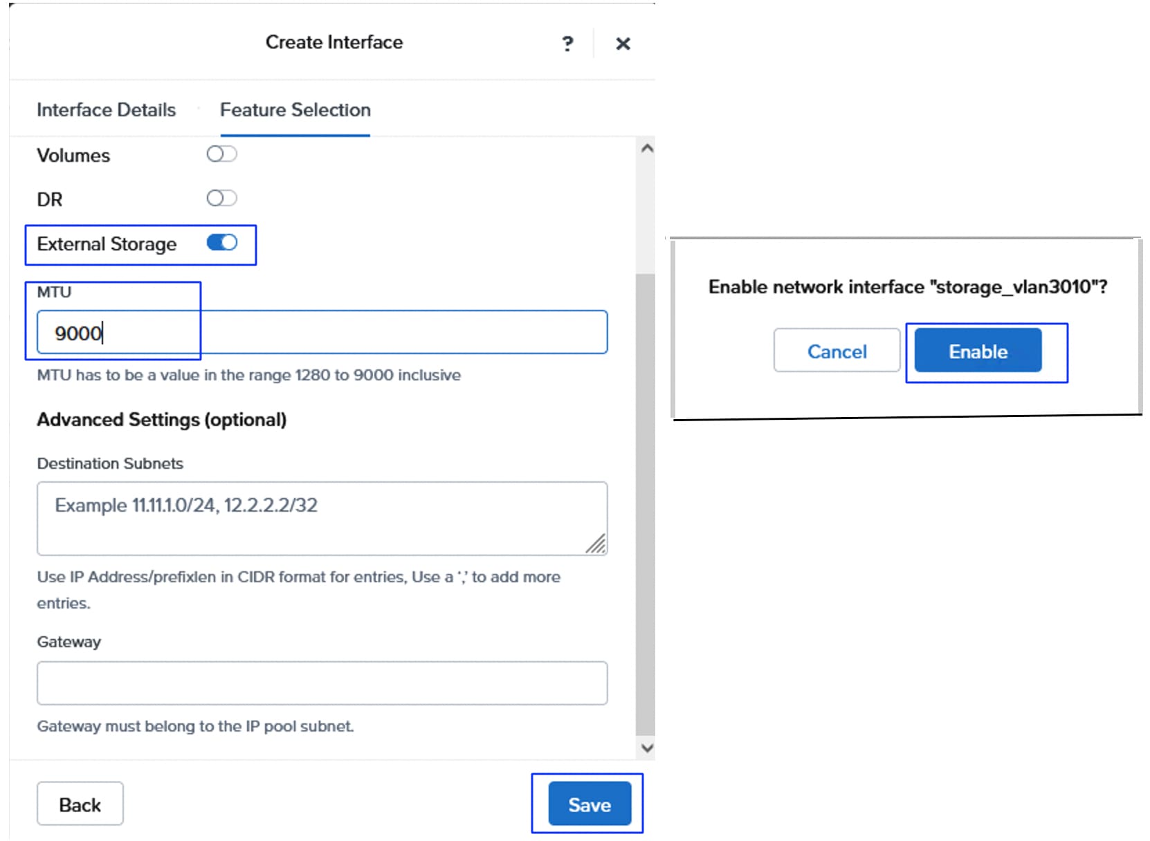
Step 10. A configuration job starts to create the interface. Wait until the job completes, then create a second External Storage Interface using storage VLAN 3020, following the previous steps. When the second configuration job completes, there will be two External Storage Interfaces, and the cluster can be connected to the Pure Storage array.
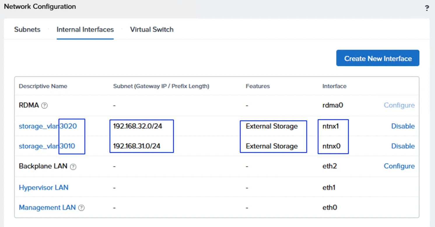
Step 11. Once the Storage interfaces are created, connectivity to the FlashArray can be tested by logging into the Controller VM. SSH to one or all CVMs using the nutanix login and Nutanix/4u password. Test the storage connectivity with MTU and without fragmenting the packets. Execute the ping commands on each controller as shown below:
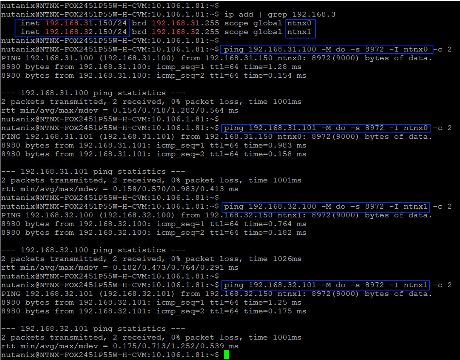
Step 12. Attach the storage to the Nutanix cluster. Go to Storage > Attach External Storage. Select Pure Storage FlashArray from the External Storage Vendor drop-down list and click Next. Provide a name (pureafxl170) to the external array and enter the FlashArray management IP and then the username and password created earlier with administrative privileges for Realm+Pod combination for each deployment type. Click Next. For the brownfield deployment type, user fsntnxm6-admin and its password must be used.
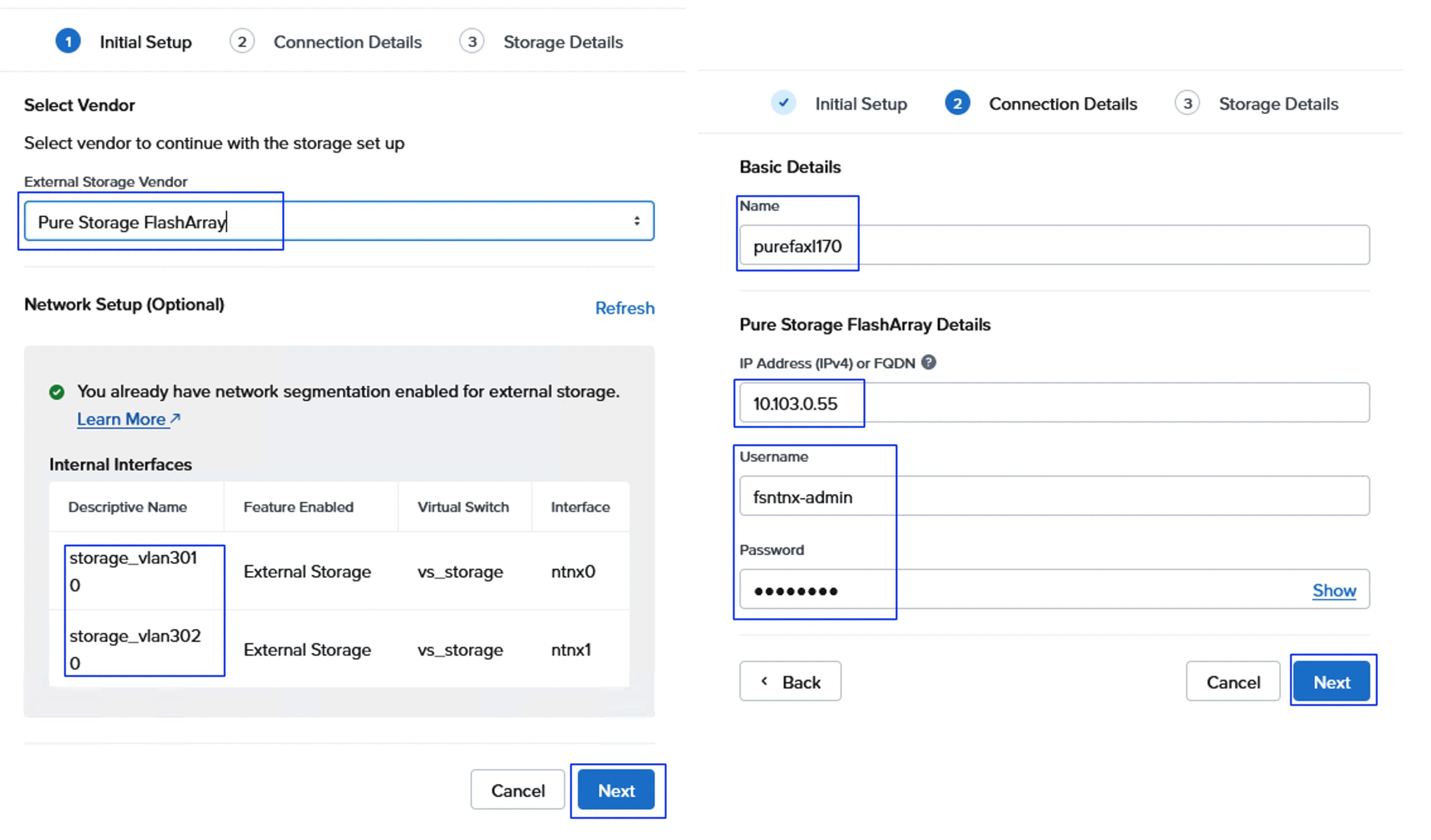
Step 13. Select the Realm and Pod created earlier for each type of cluster deployment and click Attach.
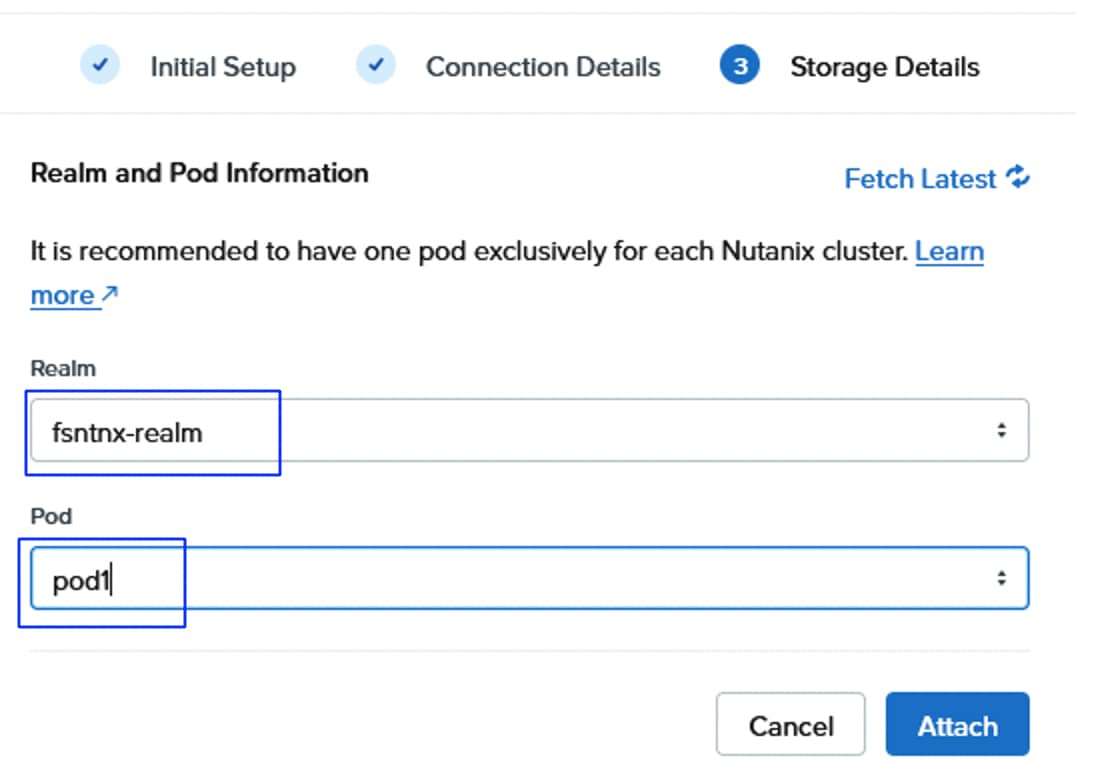
A configuration job is created to connect the NCI cluster to the external storage. The connected external storage is shown in the External Storage tab.
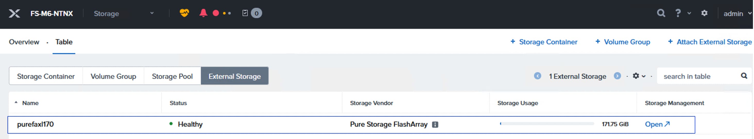
Step 14. To verify that device mapper and multipathing are properly configured for NVMe/TCP within the Nutanix Controller VMs (CVMs) for an NCI cluster using external storage, run the following commands on one of the CVMs. Ensure each volume has four active paths to the FlashArray which confirms both the ports on each FlashArray storage controller is accessible from the host.
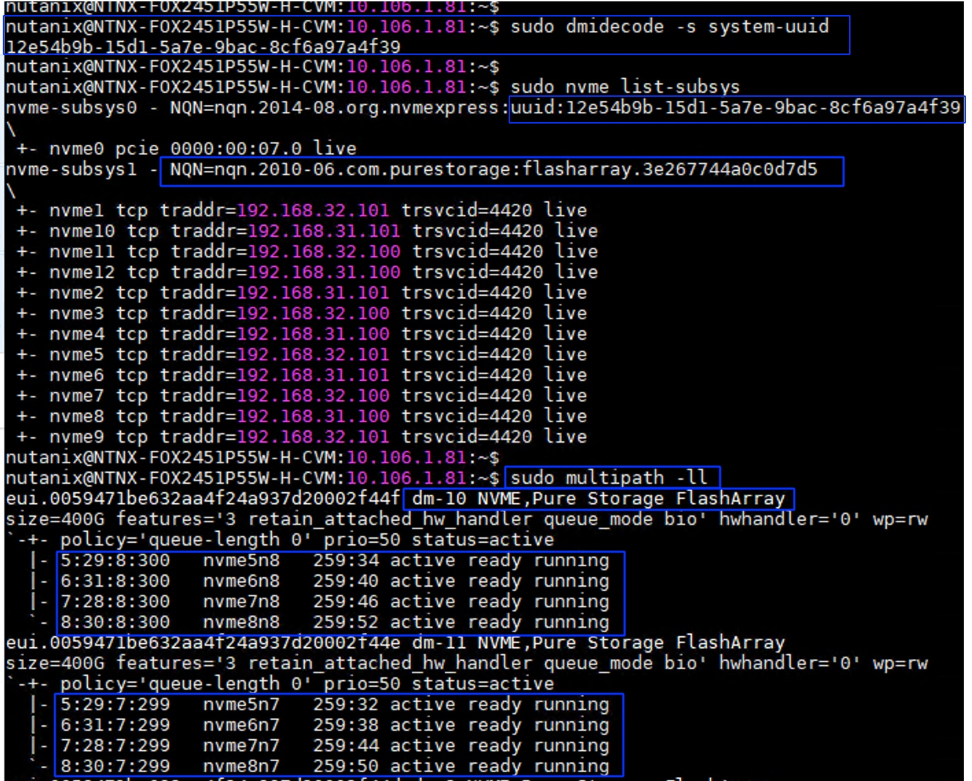
Configure Virtual Machine Networking
As mentioned in the previous sections, a separate pair of vNICs is created for virtual machine networking. A dedicated switch is set up with these vNICs, and several subnets (networks) are configured.
Procedure 1. Configure New Virtual Switch for VM’s Networking
Step 1. On the Prism element of the Nutanix cluster, select Settings from the drop-down list and go to Network > Network Configuration > Virtual Switch. Click Create VS. Provide a name as vs_guestnws and set MTU as 1500. Leave the Standard Configuration method selected and click Next.
Step 2. Set the bond type to Active-backup or Active-Active with MAC pinning. Under the Hosts box, expand each host and select eth2 and eth3 interfaces as uplinks for the vs_guestnws vSwitch. Hover the mouse on the i symbol. A window opens showing the details of each interface which helps us to identify the right interfaces easily. Click Create when the correct vNICs are selected.
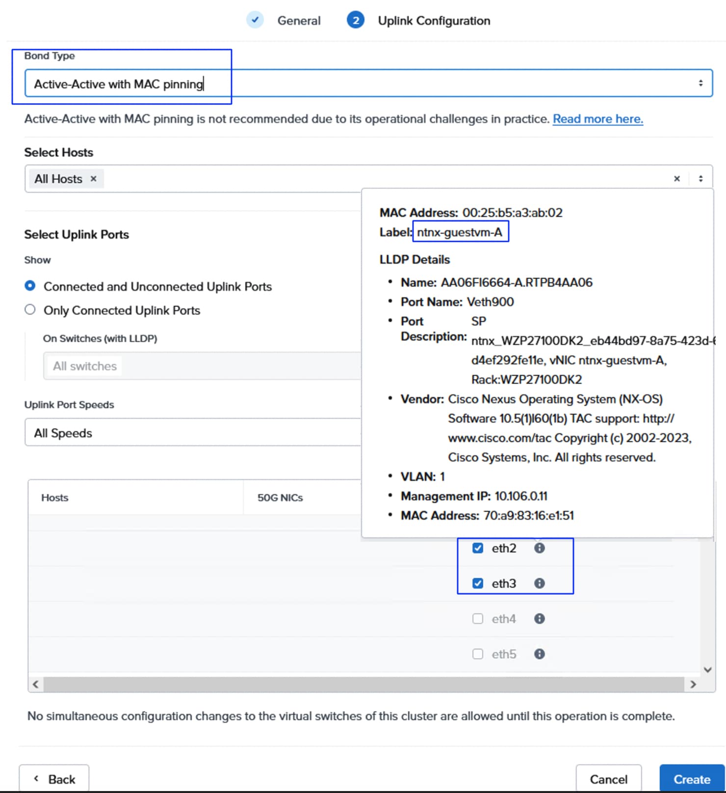
The three virtual switches display as shown below:
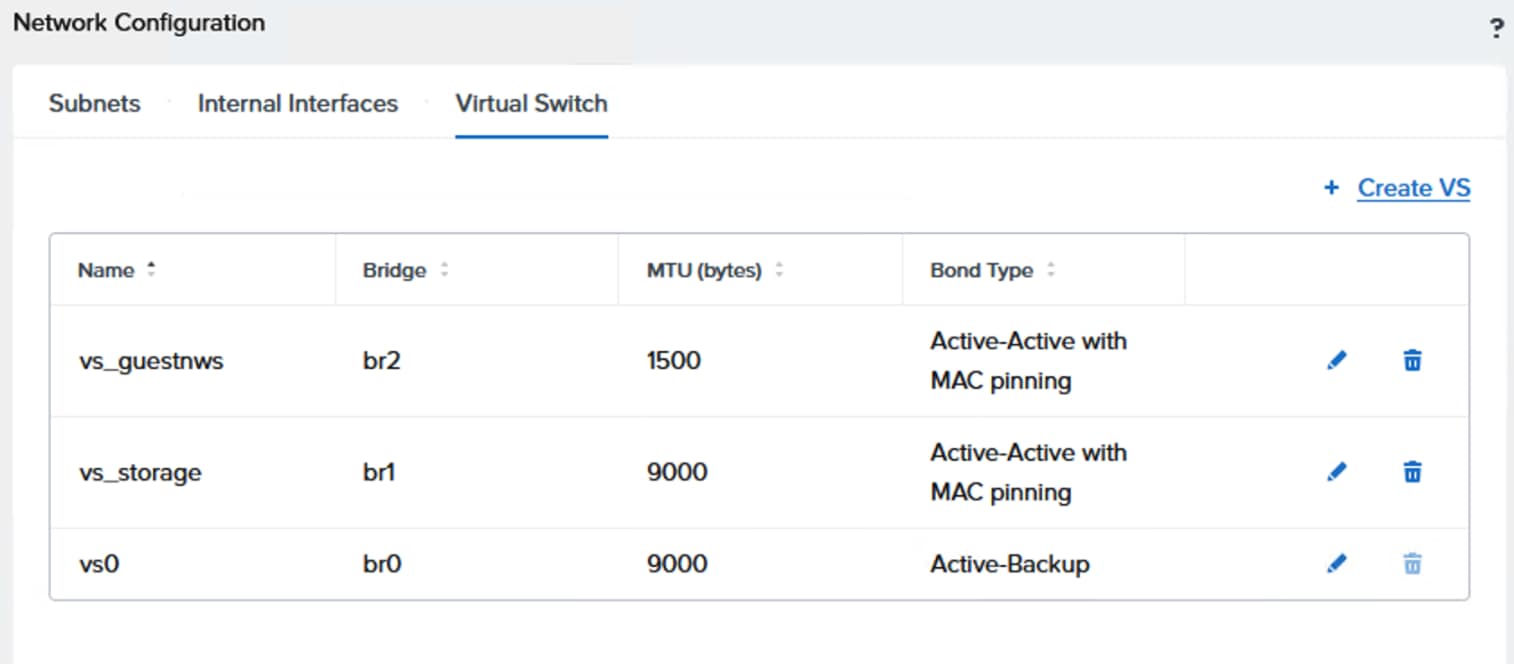
Step 3. Create Unmanaged subnets for the virtual machine networking using different VLAN IDs. Go to Subnets and click Create Subnet.
Step 4. Provide a name to the first subnet as nw-vlan1062 and select the virtual switch vs_guestnws created in the previous step. Enter 1062 for VLAN ID and click Save.
Step 5. Repeat step 4 to create two more subnets with VLAN IDs 1063 and 1064. Later, the guest VMs need to be attached to these subnets for guest management traffic.
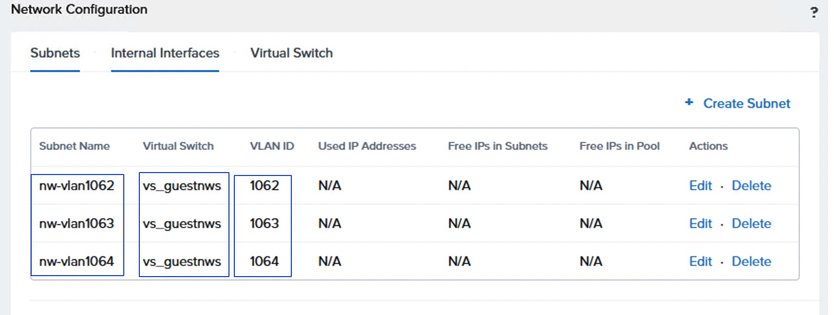
Procedure 2. Enable VM High Availability
Step 1. To enable High Availability (HA) to the VMs running on the Nutanix cluster, select Settings from the drop-down list, go to Data Resiliency > Manage VM High Availability and select the Enable HA Reservation checkbox then click Save.
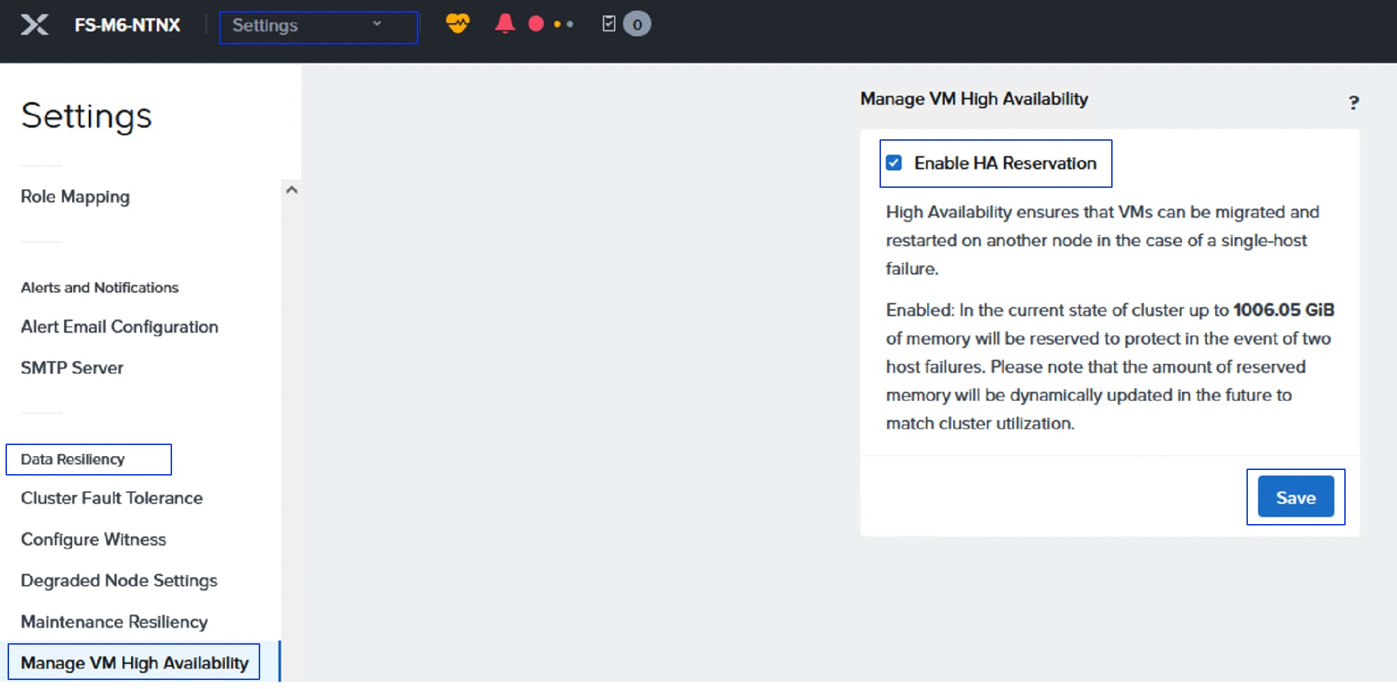
Modify Default Passwords on AHV and CVMs
It is very important to modify the default passwords of AHV root and CVMs nutanix user passwords on all the AHV and CVMs.
Procedure 1. Reset the default administrative passwords on the AHV hypervisors and the Nutanix controller VMs
Step 1. Run the scripts on one of the CVMs to reset the passwords:
## Logon to a CVM and execute below command to reset password for nutanix user. Enter a new password for nutanix user for all the CVMs
sudo passwd nutanix
## Logon to a CVM and execute below command to reset password for root user. Enter a new password for root user for all AHV nodes.
echo -e "CHANGING ALL AHV HOST ROOT PASSWORDS.\nPlease input new password: "; read -rs password1; echo "Confirm new password: "; read -rs password2; if [ "$password1" == "$password2" ]; then for host in $(hostips); do echo Host $host; echo $password1 | ssh root@$host "passwd --stdin root"; done; else echo "The passwords do not match"; fi
## Logon to a CVM and execute below command to reset password for admin user. Enter a new password for admin user for all AHV nodes.
echo -e "CHANGING ALL AHV HOST ADMIN PASSWORDS.\nPlease input new password: "; read -rs password1; echo "Confirm new password: "; read -rs password2; if [ "$password1" == "$password2" ]; then for host in $(hostips); do echo Host $host; echo $password1 | ssh root@$host "passwd --stdin admin"; done; else echo "The passwords do not match"; fi
## Logon to a CVM and execute below command to reset password for nutanix user. Enter a new password for nutanix user for all AHV nodes.
echo -e "CHANGING ALL AHV HOST NUTANIX PASSWORDS.\nPlease input new password: "; read -rs password1; echo "Confirm new password: "; read -rs password2; if [ "$password1" == "$password2" ]; then for host in $(hostips); do echo Host $host; echo $password1 | ssh root@$host "passwd --stdin nutanix"; done; else echo "The passwords do not match"; fi
## Run final NCC check for default passwords
ncc health_checks system_checks default_password_check
Step 2. Remediate all the alerts, failures, and warnings until they disappeared. Select Health > Actions > Run NCC Check.
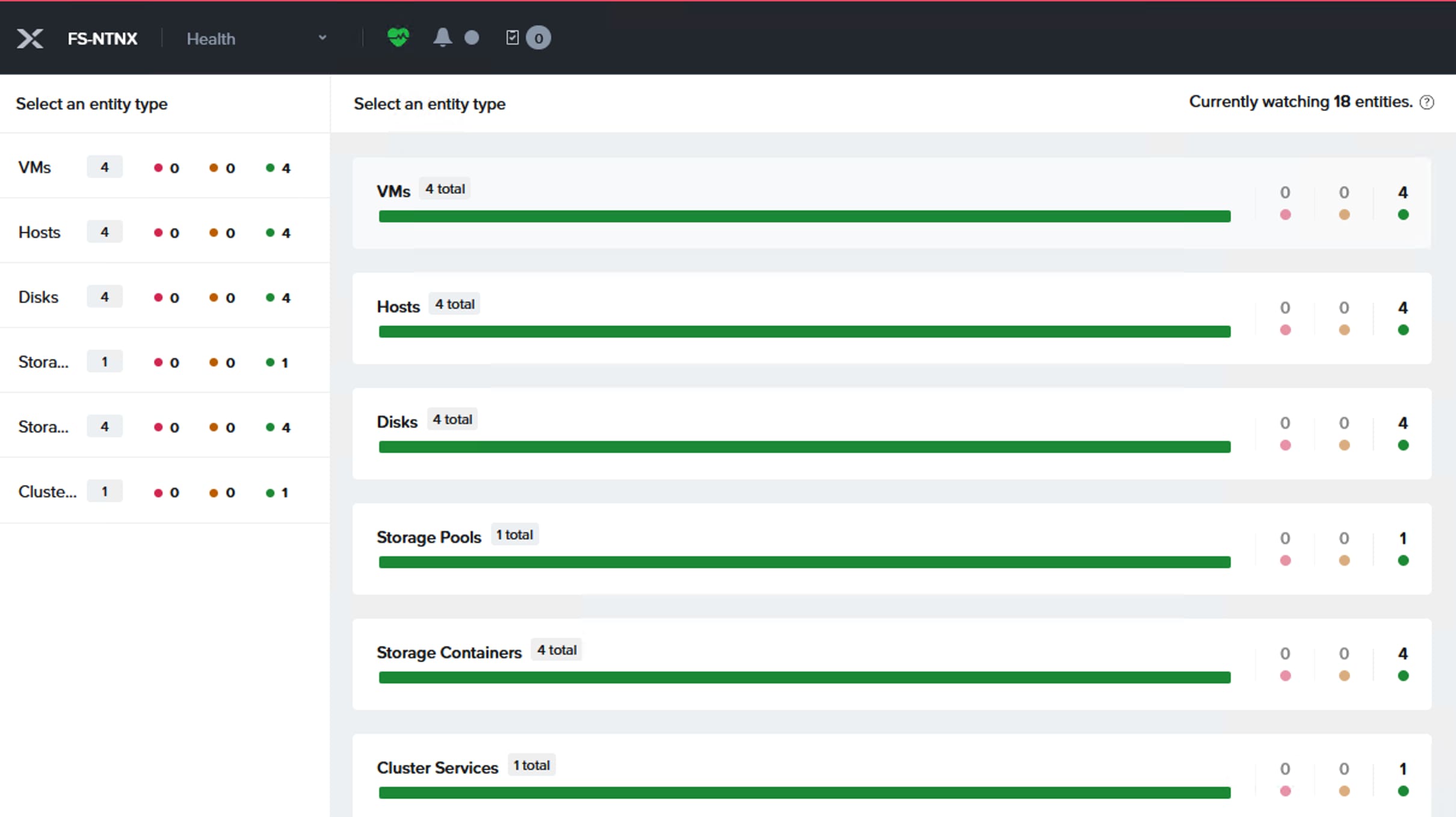
Prism Central Installation and Configuration
Deploying Prism Central using Prism Element is much easier compared to other methods of installing Prism Central. Ensure the Prism Element can reach internet by configuring the required Proxy and DNS settings.
Procedure 1. Configure the required proxy and DNS settings
Step 1. Before deploying a Prism Central on the Nutanix cluster, set Data Service IP for the cluster. Select Settings from the drop-down list then go to General > Cluster Details. Enter an IP address for Data Services IP and click Save.
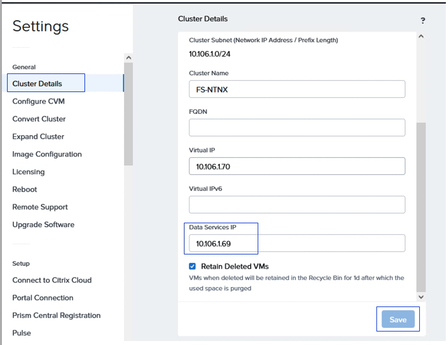
Step 2. From the Home page of Prism Element of the newly provisioned Nutanix cluster, click Register or deploy new Prism Central link.
Step 3. From the Prism Central Window, provide a name for the Prism Central VM and select the latest PC version (7.5.0.1). Select the Only show compatible versions checkbox to list only the compatible versions of Prism Central for the Prims Element. Click Next. From the Size and Scale window, select Small (S) option for the VM size and scale and click Next.
Step 4. From the Configuration window, select the VM subnet defined in the previous sections, provide Subnet Mask, Gateway IP, a valid DNS (required for Cisco Intersight Connectivity) and NTP IPs. Select the FlashArray attached to the cluster and provide the IP address for the Prism Central. Click Deploy.
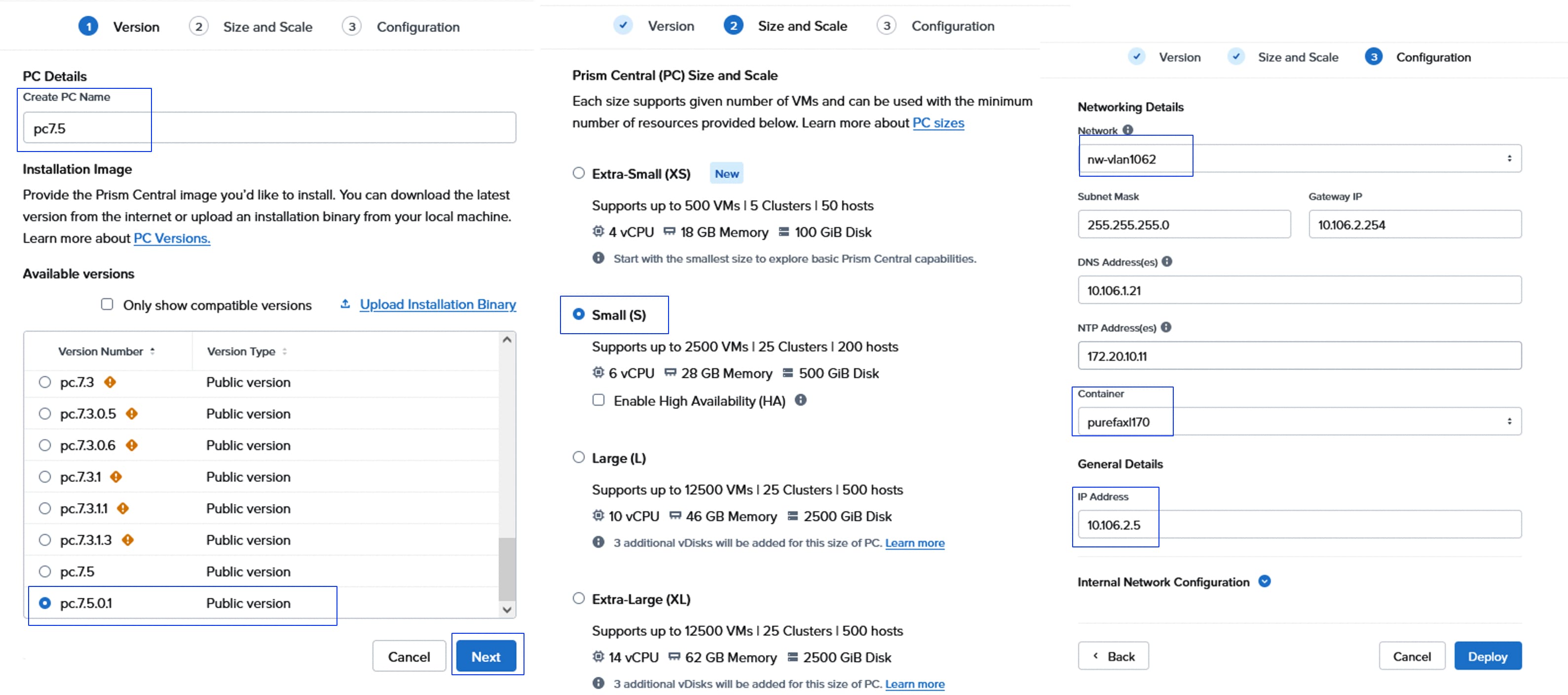
Step 5. Multiple tasks are created for downloading and deploying the PC and the deployment takes about 40 to 45 minutes. When the PC is deployed successfully, log into the PC using the IP address <https://PC-IP:9440> default user and password (admin/Nutanix/4u).
Note: The default password must be changed on first login.
Step 6. Configure the Proxy in the Prism Central. Go to Admin Center > Settings > Network > HTTP Proxy > Configure Proxy.
Step 7. Install the Foundation Central in Prism Central which is required for the FlashStack with Nutanix cluster provisioning and expansion. Enable the marketplace, go to Admin Center > My Apps > Market Place. Click Enable Marketplace. This task takes few minutes to enable the marketplace.
Step 8. Go to Admin Center > Marketplace. Look for the Foundation Central application and click Get to install the FC v1.8.0.
Note: Foundation Central version 1.10 must be used when deploying or expanding the Nutanix Cluster on FlashStack with Cisco UCS. Do not use version 2.0 and is not supported by Cisco. If you deploy FC 2.0, reverting to version 1.8 is a tedious task and not supported.
Note: FC v1.10 is not yet available on marketplace at the time of writing this CVD. Therefore, the LCM offline bundle for FC 1.10 must be used to upgrade Foundation Central version from 1.8 to 1.10.
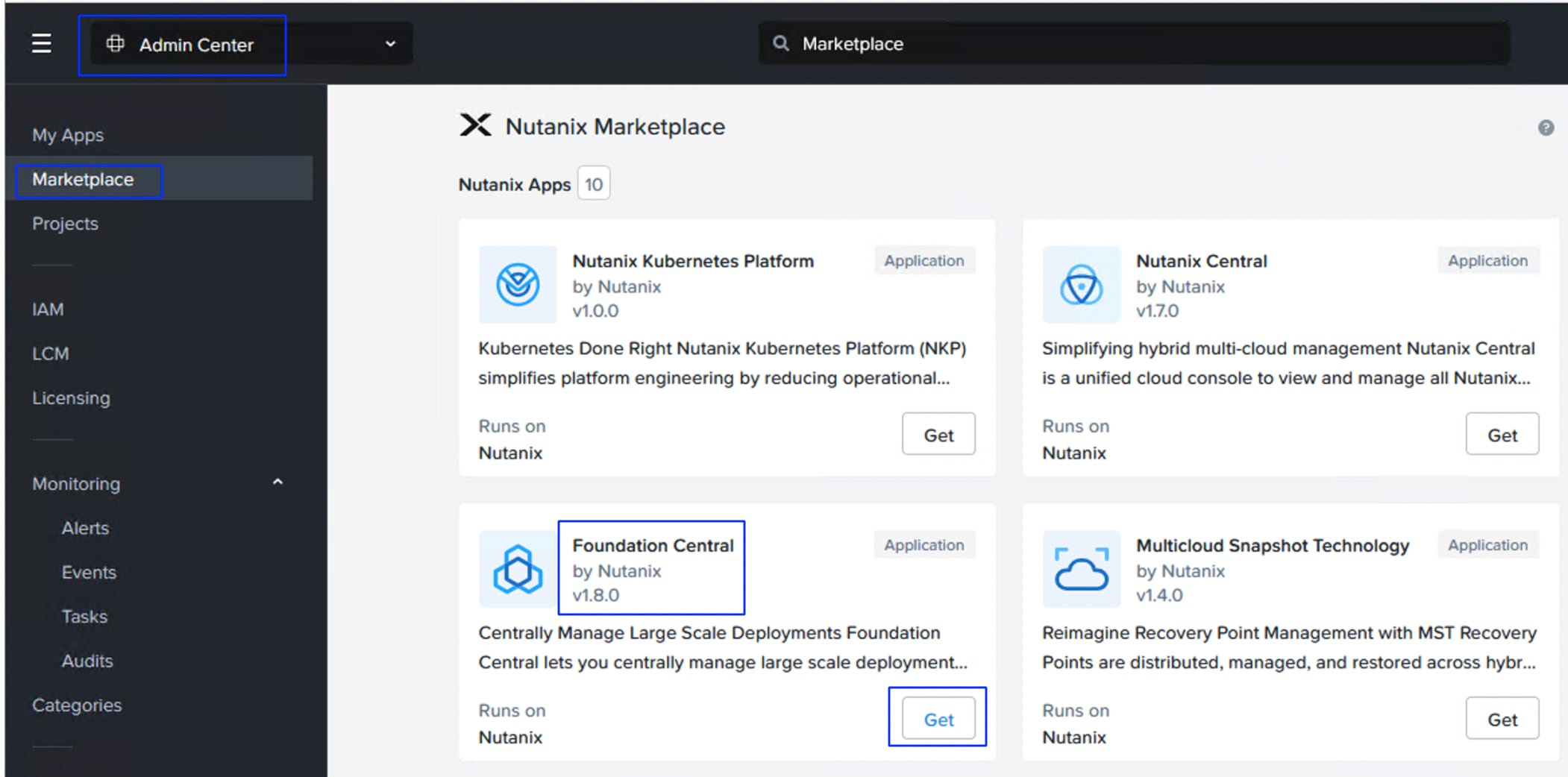
Step 9. Click My Apps and click Deploy to start the installation FC v1.8. Wait a few minutes until FC becomes a running state.
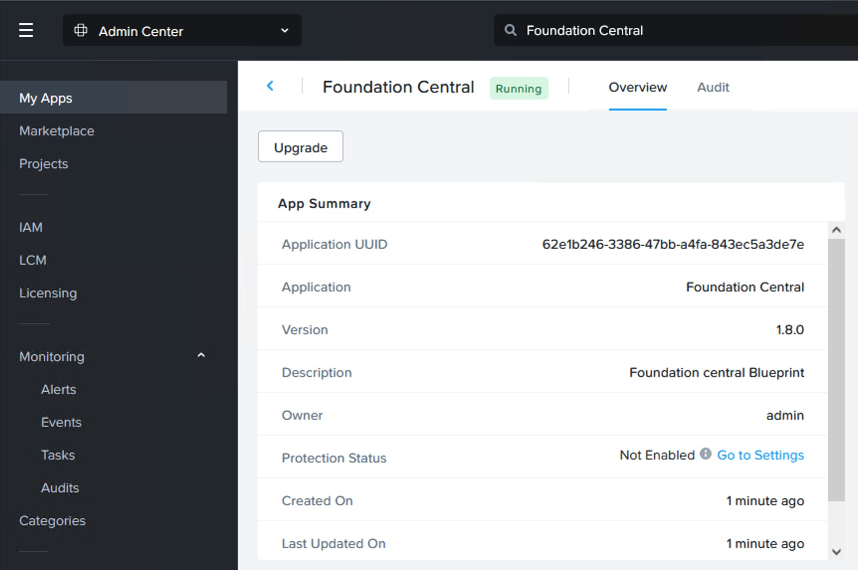
Step 10. Download the Foundation Central LCM Bundle v1.10 from the Nutanix Portal.
Step 11. Before upgrading the Foundation Central from 1.8 to 1.10, register the newly provisioned Nutanix Cluster to Prism Central. This is required to successfully run the LCM of Prism Central. To register Nutanix cluster to Prism Central, log into Prism Element and click Register or Deploy the Prism Central. Since Prism Central is already deployed on the Nutanix Cluster, click Connect to register the Nutanix Cluster to Prism Central.
Step 12. From the Prism Central window, click Next. Provide the Prism Central IP, port and credentials then click Connect.
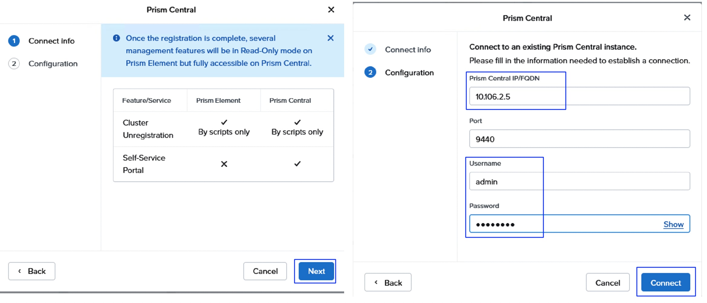
Step 13. Once registered, verify you can see the Prism Central VM name and IP addresses on the Prism Element as shown below:
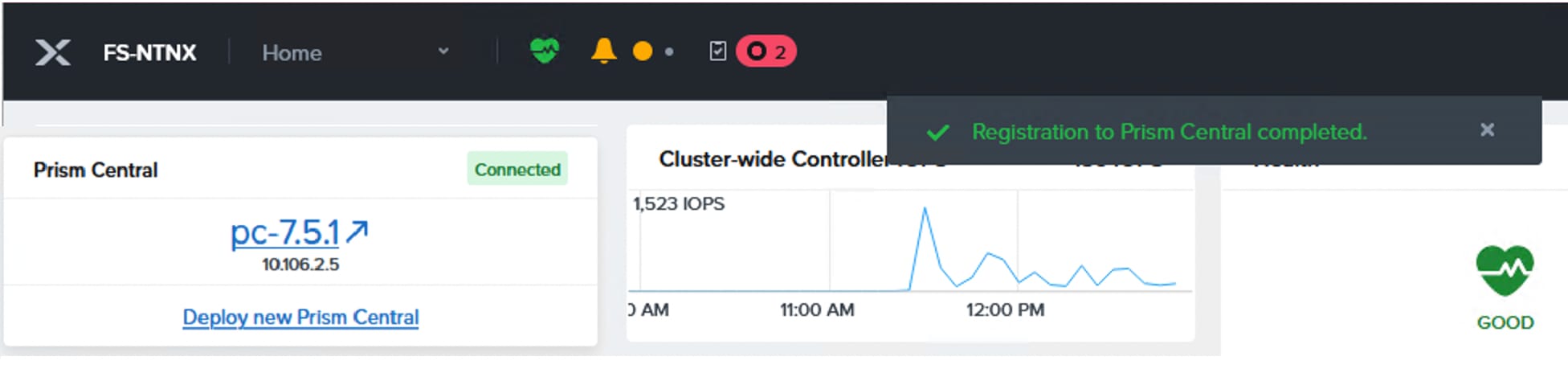
Step 14. Upload the FC v1.10 Offline bundle to the LCM, go to Admin Center > LCM > Prism Central. Click the name of the PC server. Click Summary > Actions > Upload Bindle. Browse the FC v1.10 LCM offline bundle and click Upload Bundle.
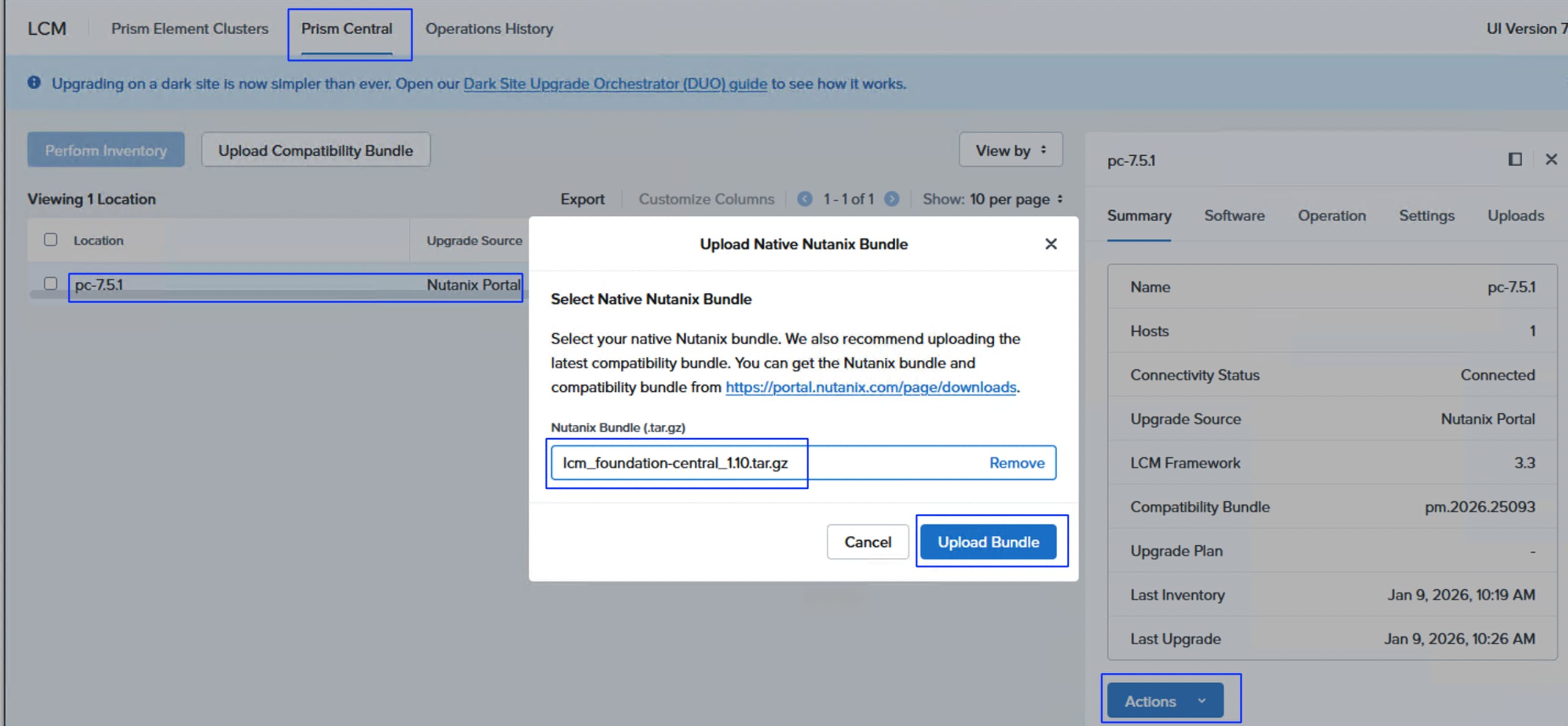
Step 15. After uploading the LCM offline bundle, check the PC server and click the ellipses and then click Perform Inventory. After successful completion of Perform inventory task, select the PC server, click the ellipses and then click Create Upgrade Plan.
Step 16. From the pop-up window, click Change Upgrade Version. From the Change Upgrade Version window, select 1.10 and click Save. The upgrade version must display 1.10 (instead of 1.8.2) as shown below. Click Next.
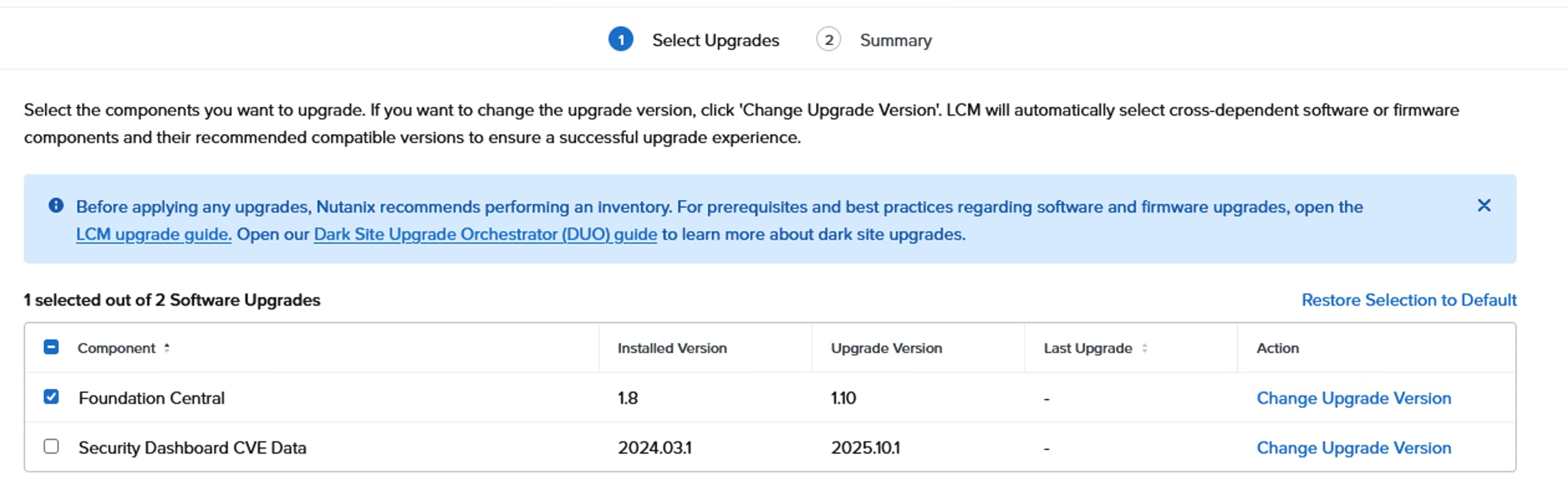
Step 17. Wait for the upgrade to complete and verify the Foundation Central version is now 1.10 as shown below:
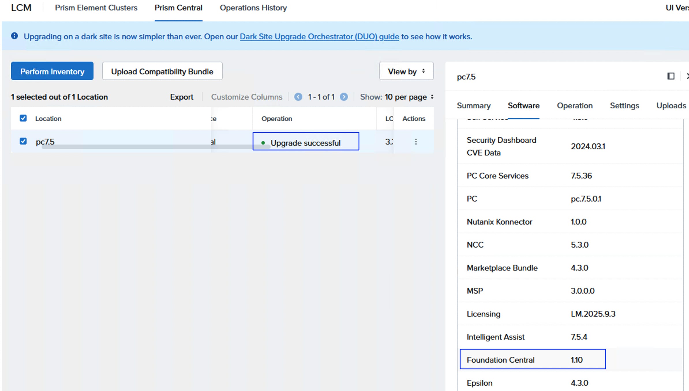
Step 18. With the updated Foundation Central v1.10 of Prism Central, you can provision a new cluster or expand the already existing Nutanix cluster. However, when provisioning or expanding the Nutanix cluster using Foundation Central via Prism Central, an HTTP server is needed for hosting the files. For this validation, Cisco IMM Toolkit VM is used which provides an easy HTTP server which can host the AOS and AHV installation files, however any anonymous HTTP server of your choice can be used. Download the latest IMM Transition Toolkit OVA. Deploy the IMM transition Toolkit VM by importing the OVA file into ESXi. Upload the AOS and AHV installation files into the IMM Transition HTTP server. Log into the IMM Toolkit via web browser using the credential set during the deployment. Create a folder for storing the Nutanix installation files, if desired. Click File Upload, then drag-and-drop the AOS, AOS metadata and AHV or ESXi installation files you will use for the installations.
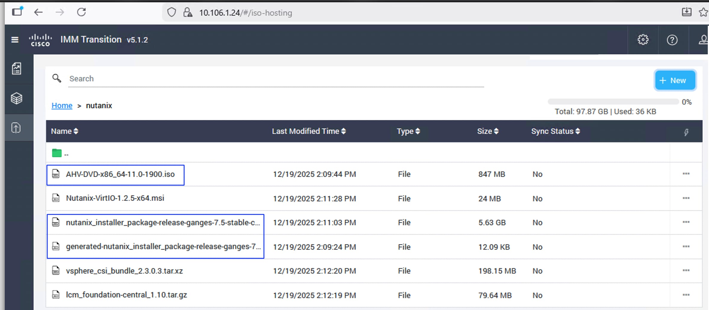
Install Device Connector in Prism Central
Follow this procedure to install the Intersight Device Connector in Prism Central for unified visibility and management. See Cisco Device Connector for more details on the prerequisites and supported software and hardware components.
Procedure 1. Install Intersight Device Connector in Prism Central
Step 1. Log into Prism Central, go to Admin Center > Marketplace. Search for Cisco to identify Cisco Intersight Device Connector, click Get and then click Deploy. Wait for a few minutes until the status becomes running.
Step 2. To claim the Device connector, go to MyApps > Cisco Intersight Device Connect and click Open. A new web browser window opens with the Device ID and Claim Code. Copy the Device ID and Claim Code to claim this Prism Central instance in Cisco Intersight.
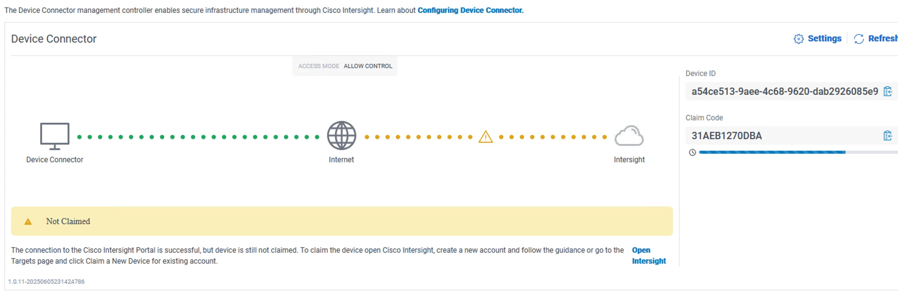
Step 3. Log into Intersight, go to System > Targets and click Claim a New Target. Select Hyperconverged and then select Nutanix. Enter the Device ID and Claim Code to claim the Prism Central instance.
Step 4. Go to Operate > Nutanix Clusters > FS-NTNX (your AVH cluster) to view the cluster details.
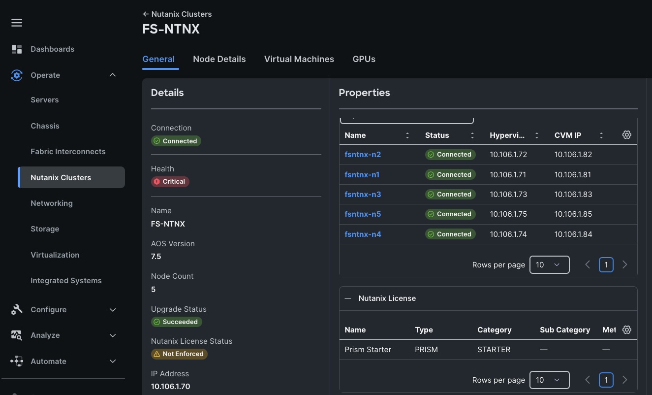
Nutanix Life Cycle Manager (LCM) simplifies the IT infrastructure life cycle operations by delivering a simple, fast, and deterministic methodology for performing software and firmware upgrades. Nutanix LCM intelligently handles software and firmware dependencies, automates the entire upgrade process across all clustered hosts without impacting applications or data availability, all from the Nutanix Prism platform.
● LCM v3.3 is included with AOS 7.5 and is capable of automatically upgrading itself to the latest version during an inventory job.
● LCM manages upgrades for Nutanix cluster software components such as AOS and AHV.
● However, for compute-only nodes connected to external storage (such as FlashStack with Nutanix using Pure Storage FlashArray), LCM does not handle server firmware updates for any hardware vendor. Therefore, only Nutanix software updates are shown in LCM.
● Server firmware updates for compute-only nodes must be managed through Cisco Intersight.
● For FlashArray Purity upgrades, Pure Storage Pure1 is used for storage firmware and software lifecycle management.
This division of upgrade responsibilities reflects the integrated management approach where Nutanix LCM handles Nutanix software lifecycle, Cisco Intersight manages server firmware lifecycle, and Pure Storage Pure1 manages storage array upgrades, ensuring coordinated and specialized management across the stack in FlashStack with Nutanix solutions.
Nutanix Life Cycle Manager (LCM) software upgrades can indeed be run directly on a single cluster via Nutanix Prism Element, which is included with every Nutanix cluster for single cluster management. For managing and performing upgrades across multiple clusters simultaneously, Nutanix Prism Central is used, providing a centralized workspace to monitor and manage multiple clusters from one interface.
Note: Before performing any upgrades, it is essential to review the interoperability matrix to ensure that you don’t end up installing unsupported version of components—including AHV, AOS, Purity, and server firmware. This proactive check helps prevent compatibility issues and ensures a smooth, reliable upgrade process across the entire environment.
Procedure 1. Update software using Prism Central LCM
Step 1. Log into Prism Central, go to Admin Center > LCM > Prism Element Clusters.
Step 2. Select the Nutanix cluster you want to update from the lister clusters.
Step 3. Run the Perform Inventory job first. This inventory process fetches the latest available software versions and updates for the cluster.
Step 4. Once the inventory job successfully completes, if LCM detects any new software updates, the option of Create Upgrade Plan is enabled. If no updates are found, the Create Upgrade Plan option remains grayed out and unavailable.
Step 5. If Create Upgrade Plan option is enabled for your cluster, click it and start the upgrade process to the desired version.
NCI Compute Cluster Expansion using Prism Central
This section provides steps to scale the existing Nutanix cluster by adding a new node to the cluster. For expanding the Nutanix cluster, Foundation Central via Prism Central must be used and FC Appliance cannot be used for cluster expansion. Ensure The new node(s) to be added to the cluster must be fully discovered in Cisco Intersight with no server profile associated and belong to the same organization as the existing nodes in the cluster.
Foundation Central is used to onboard the new node(s) and perform an initial node preparation, which installs the AHV hypervisor and AOS software. The appropriate version of AHV and AOS matching what is already installed on the cluster nodes must be downloaded and hosted on an anonymous HTTP server, as with the initial installation process. Afterwards, an expansion job starts from Prism Central to add the newly prepared node(s) to the existing cluster.
Procedure 1. Prepare the node
Step 1. Add Intersight API and Secret keys are being added into the newly installed Foundation Central in Prism Central. Log into the Prism Central, go to Foundation Central > Foundation Central Settings > Connect Hardware Provider. Provide a Connection Name as Intersight and select the Cisco Intersight from the Hardware provider drop-down list. Select Saas for the Intersight Deployment Type. Provide the API Key and Secret key for the Cisco Intersight SaaS being used.
Step 2. Click API Keys Management and click Generate API Key. Provide a name for the API key and click Generate API Key.
Step 3. Click Nodes > Manually Onboarded tab and click Onboard Nodes. Ensure Cisco Intersight is selected as the Hardware provider and Node Management mode is set to IMM. Click Next. Select the required nodes that you want to use for deploying Nutanix Cluster. Click Onboard Nodes.
Step 4. For this validation, the Cisco UCS C240 M7 C-series server is added to the existing Cisco UCS M7 based Nutanix cluster (greenfield). For brownfield type deployment, the Cisco UCS B200 M5 blade is added to the existing cluster.
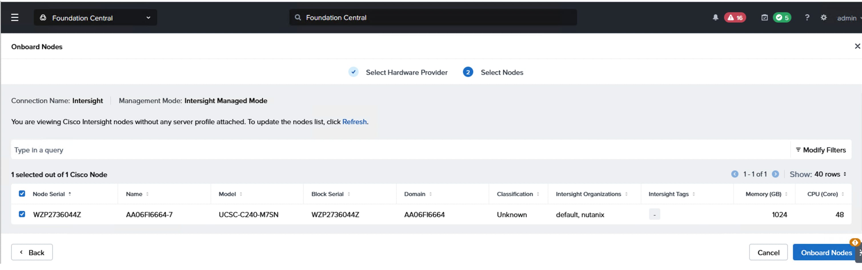
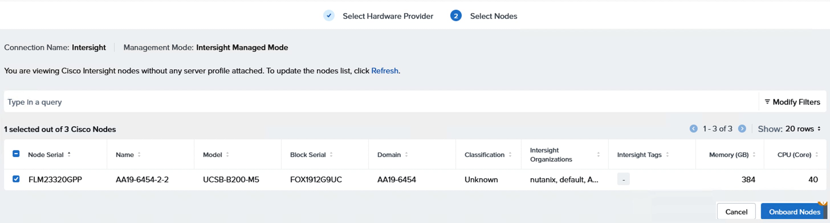
Step 5. Do not select the onboarded node but click Prepare Node for Cluster. Select the Nutanix Cluster to be extended and then select the nodes to be added to the cluster.
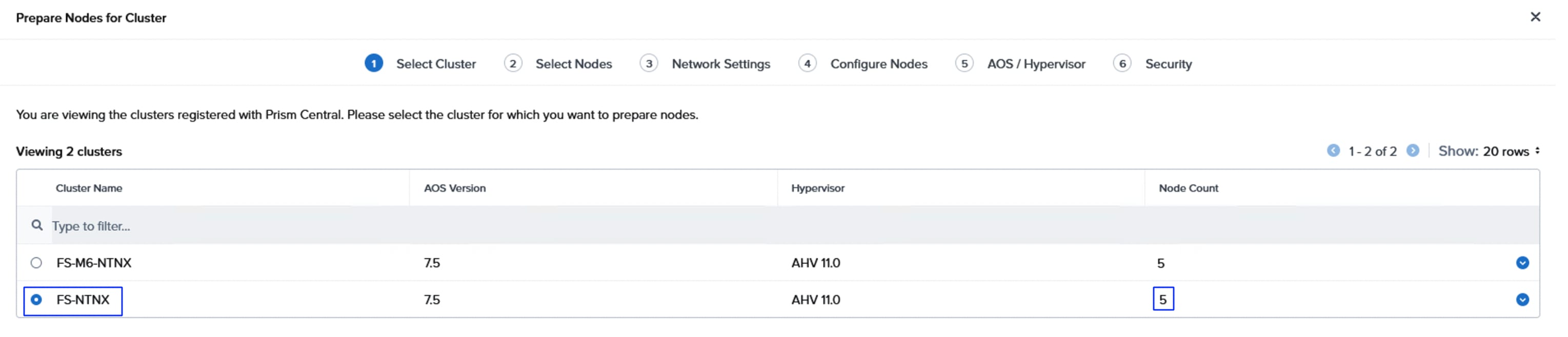
Step 6. From the Network Settings tab, enter networking details (Gateway IP, Netmask, Host and CVM VLAN and MTU size) matching the existing configuration on the nodes in the cluster. Click Next.
Step 7. From the Configure Nodes window, select the UUID pool and provide the IP addresses for AHV and CVM, enter the name of the node, and select the firmware. Click Next.
Step 8. From the AOS/Hypervisor tab, enter the HTTP URLS (from UCS IMM toolkit Http server) for the AOS installation file, the associated metadata file, AHV installation file and the AHV installation file SHA256 checksum value. The SHA256 checksum for the AHV installer file is listed on the download page in the Nutanix portal. Use the versions matching the already installed versions on the cluster.
Step 9. From the Security tab, select the API key that was created in the previous steps and click Submit. Wait until the node is prepared successfully as shown below:
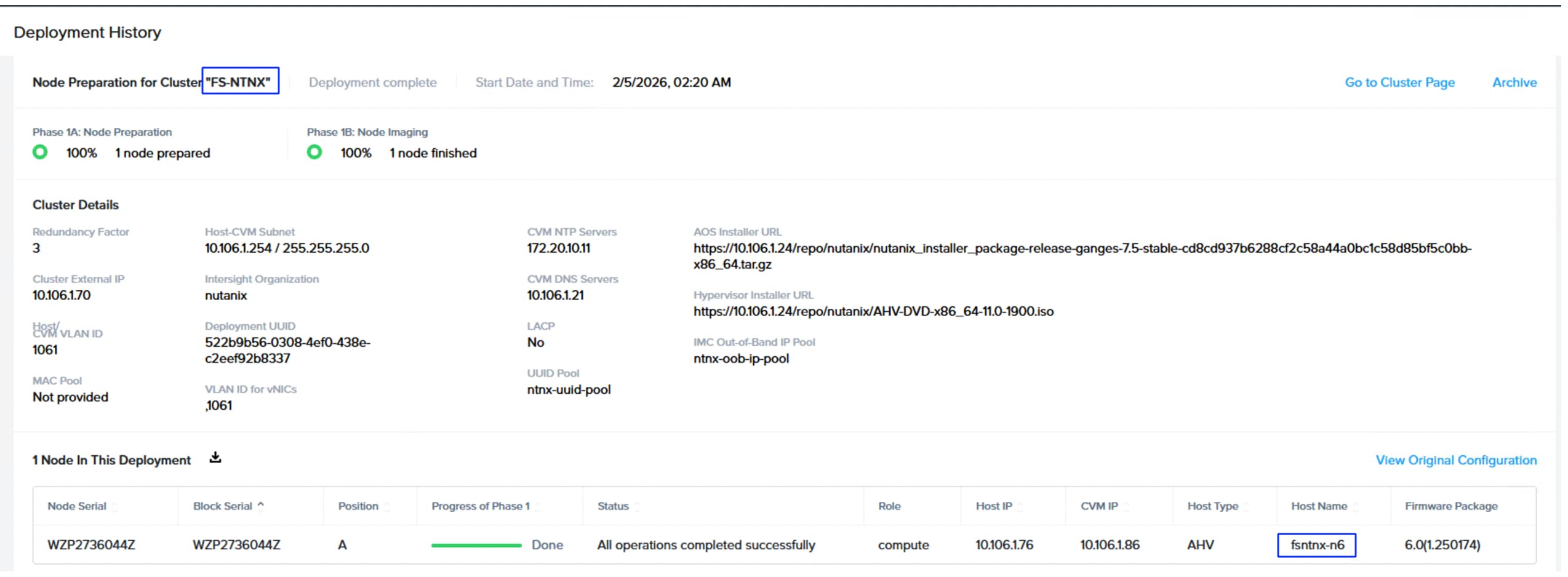
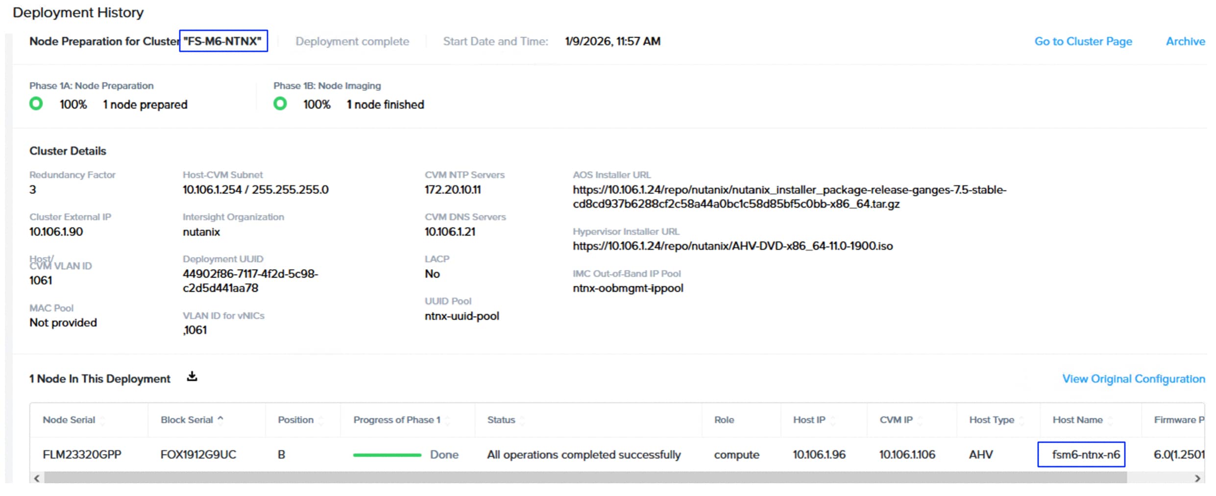
Procedure 2. Expand the Cluster
Step 1. To expand the Nutanix cluster with the prepared node, log into the Prism Central, go to Infrastructure > Hardware > Clusters. Select the cluster to be expanded, then click the ellipses and select Connect Expand Cluster.
Step 2. Select the discovered node(s) that were prepared to be added to the cluster. Click Next.
Step 3. Select HCI for the node type, even though this is a compute-only node. Click Next.
Step 4. Enter the name for the node. Leave the IPMI IPV4 address as 0.0.0.0. Click Next.
Step 5. From the Networking tab, configure the detected uplinks to the appropriate virtual switches. For example, for eth0 and eth1 interfaces, select the default virtual switch vs0, for ethe2 and eth3 select vs_guestnw switch and for eth4 and eth5 interfaces select vs_storage vswitch as shown below. For vs0, choose which interface is active and which is backup uplink. Click Next.
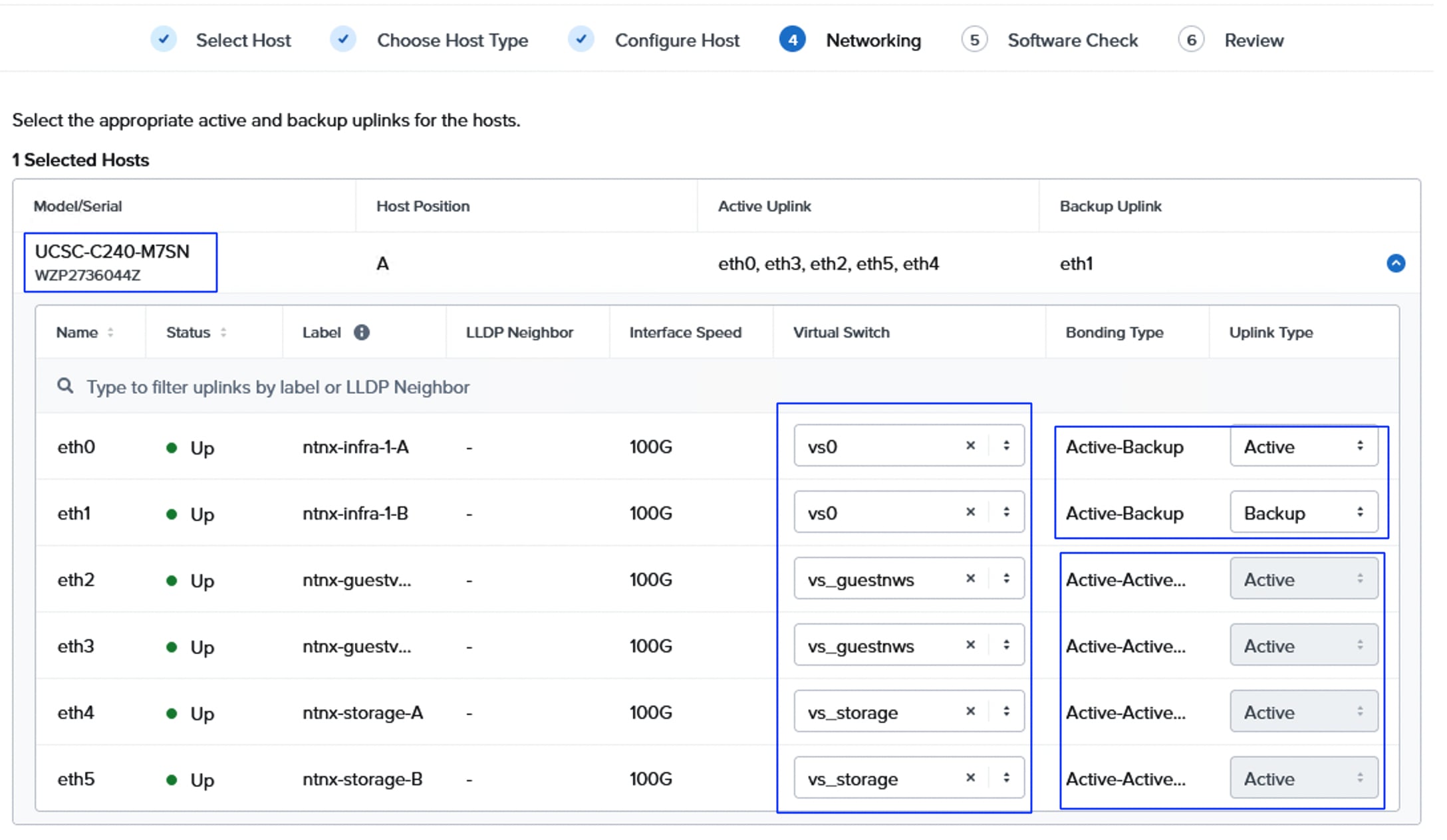
Step 6. From the software check window, ensure the node is compatible (shown with green tick mark) and then click Next. Review the node configuration and click Expand Cluster. The expand task is created to add the node to the cluster. Wait until the task executes successfully. Once the task(s) are completed successfully, verify an increase in the node count, go to Infrastructure > Hardware > Clusters > Host count.
The following screenshot shows the host count as 6 after adding the sixth node to both the clusters:
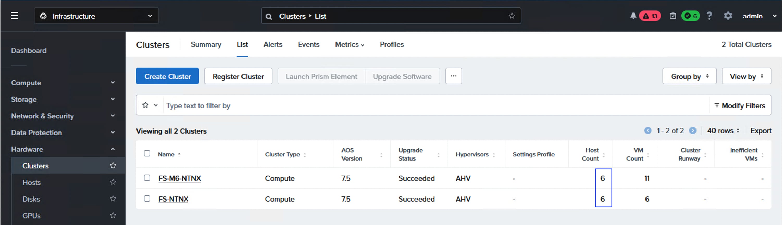
Various Guest Operating systems are supported and can be deployed on the Nutanix Cluster. See the Compatibility and Interoperability Matrix: AHV Guest OS for the complete list of features of Nutanix Cluster and Supported Guest Operating Systems. This section provides the procedure to deploy Windows Server 2025 Guest OS.
Note: Before proceeding with deployment of windows Guest VM, download the Windows ISO image from Microsoft portal and also download the latest Nutanix VirtIO drivers (Nutanix-VirtIO-1.2.5.iso) for Windows. Upload these two ISO installation files to Nutanix Cluster as Image files.
Procedure 1. Deploy Windows Server 2025 Guest OS
Step 1. Log into Prism Central, select Infrastructure > Compute > Images > Add Image. Click Add File, browse the Windows ISO file. Enter a Name to the Image and set Type as ISO and click Next. In the Placement Method window, select the Nutanix Cluster you want to this image and click Save.
Step 2. Repeat step 1 to create an image for the Windows VirtIO drivers.
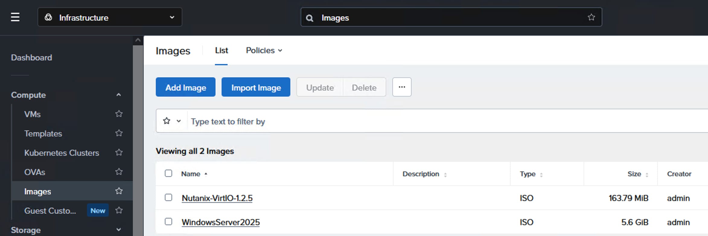
Step 3. Create a VM, go to Compute > VMs > Create VM. Provide a name to the VM, select the cluster, provide the number of VMs you want to create, set CPUs as 1, Core per CPU to 4 and Memory as 8GiB. Click Next.
Step 4. Under Disks, click Attach. Set Type to CD-ROM, Operation to Clone from Image, Image to WindowsServer2025 (Guest ISO image created in the previous step), select the cluster and set Bus Type to SATA. Click Save.
Step 5. Under Disks, click Attach. Set Type to Disk, Operation to Allocate on Storage Container, Storage Container to External Storage you created (purefaxl170), Capacity 120G and Bus Type to SCSI. Click Save.
Step 6. On Network, click Attach to Subnet. Select the Subnet (nw-vlan1062) and set Attachment Type to Access. Click Save.
Step 7. Set Boot priority to Default Boot Order (CD-ROM, Disk, Network). Select UEFI BIOS mode and optionally, select Secure Boot. Click Next.
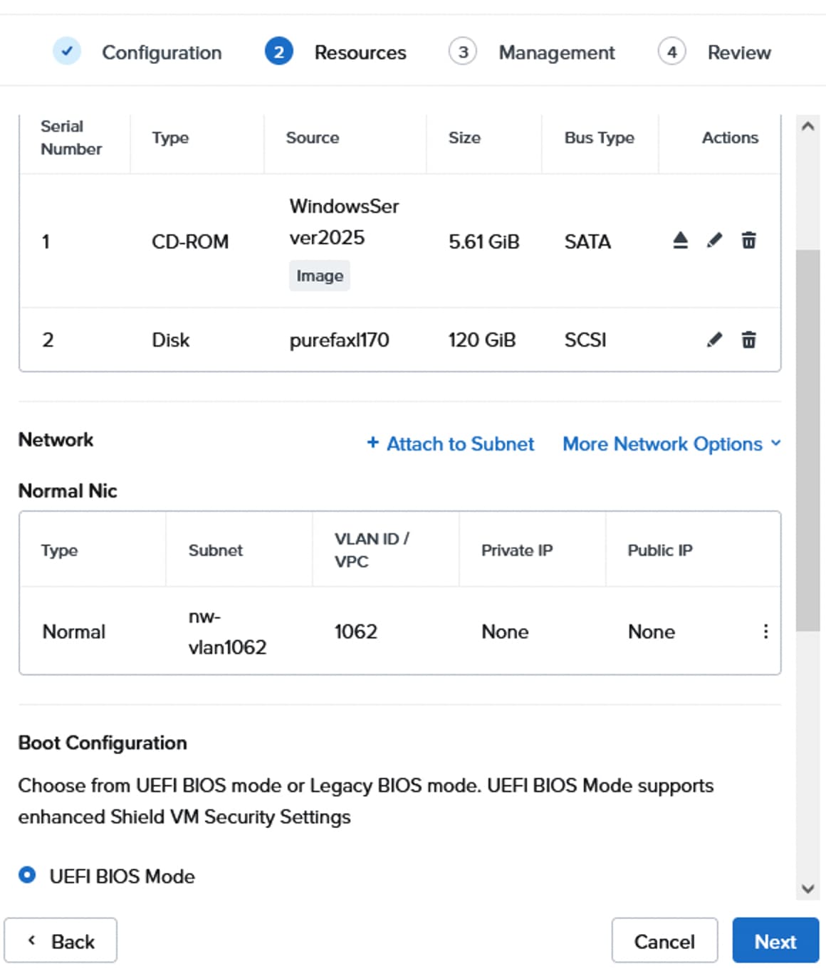
Step 8. From the Management tab, set the Time Zone and click Next. Review the Settings and click Create VM.
Step 9. Power on the VM, right-click the VM > Power Operations > Power On. Right-click the VM and select Launch Console. Send Action CTRL+ALT+DEL and press any key to start the Windows OS installation.
Step 10. Go through the installation wizards and when you reach Set Location to Install window, click Action > Mount ISO > select Nutanix VirtIO ISO file and click Mount.
Step 11. Once the Disk is mounted successfully, click Load Driver > Browse > browse through the Nutanix VirtIO ISO and select Windows Server 2025 > X64. Select VirtIO SCSI Pass-through Controller and click Install.
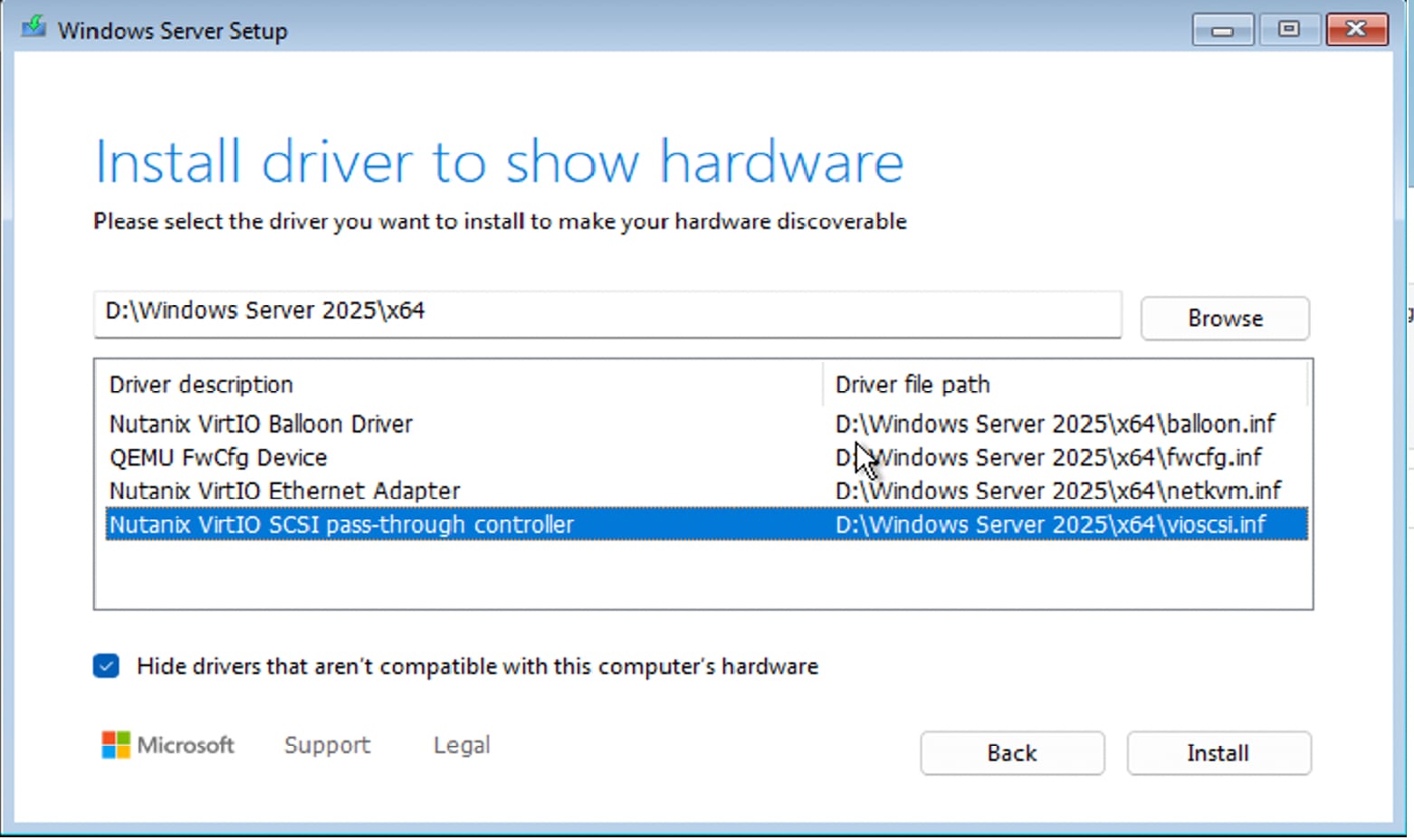
Step 12. Once the 120G OS vDisk appears, go to Actions > Mount ISO and select WindowsServer2025 image and click Mount.
Step 13. Once Mounted successfully, click Next to proceed and complete the Guest OS installation by going through the wizards.
Step 14. Once Windows is successfully installed, set the Administrator password and then log into the Windows Server.
Step 15. Install Network VirtIO drivers for windows, set CD-ROM to empty, go to Compute > VMs > right-click the VM > Update > Storage > select sata.0 > Eject.
Step 16. Select the VM(s), click the ellipses and select Guest Tools and then select Set up NGT (Nutanix Guest Tools).
Step 17. Select New NGT Installation and click Next. Select VSS and SSR services. Click Next. For automatic installation of Guest tools, select Install Automatically which requires you to provide Guest Administrator credentials. If not, select the Mount Installer option which will mount the tools to the VM so that you can log in and install the guest tools.
Step 18. Log into the Windows with Administrator account, double-click the mounted guest tools and complete the installation. Once the Guest tools installation complete, the network adapters come up and get the IP addresses assigned to it if the DHCP is configured for the subnet you have assigned.
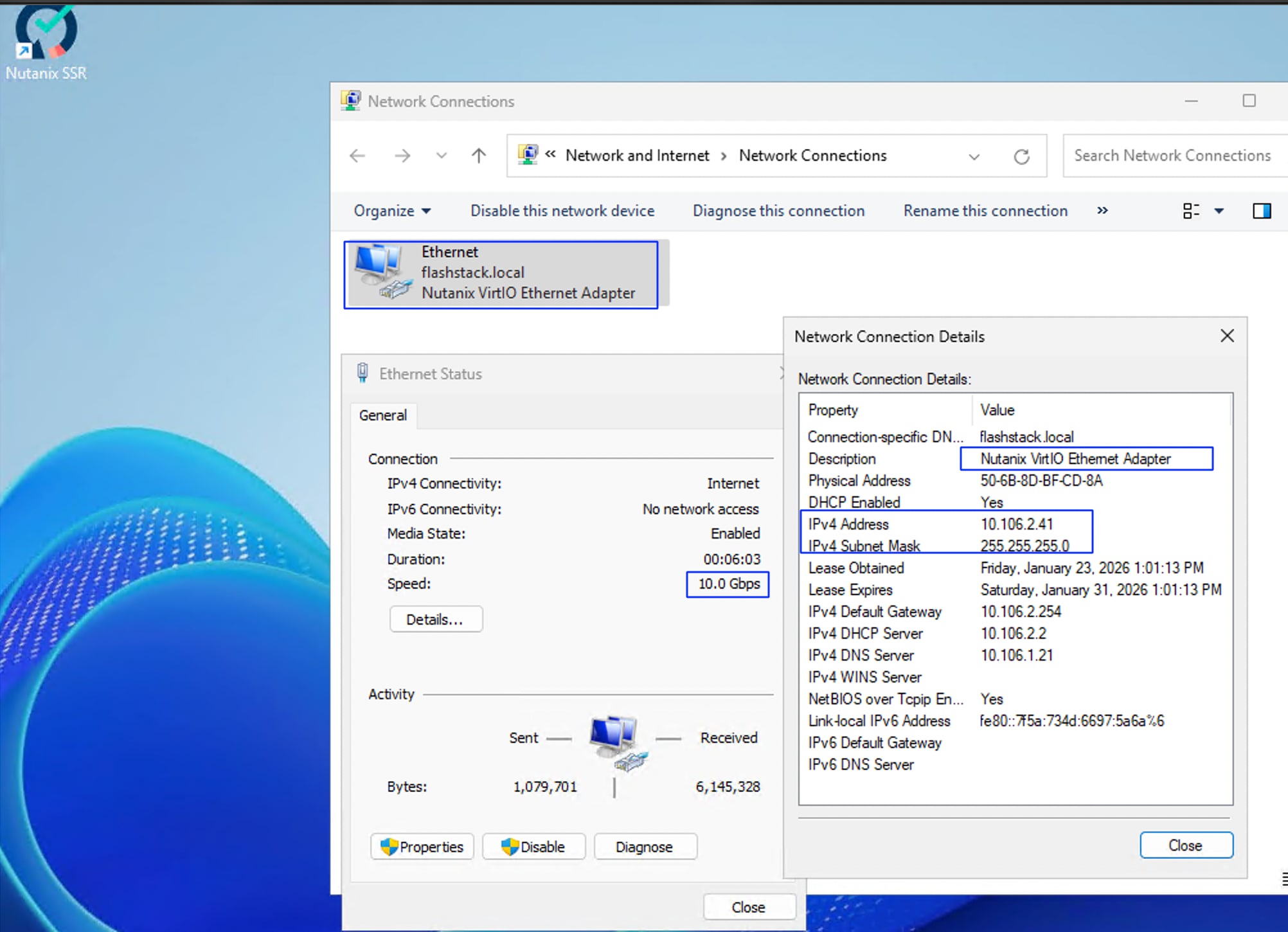
Solution Validation using Nutanix X-Ray
The purpose of this test is to validate that all solution components are optimally configured and to ensure the solution performs as expected. To facilitate this validation, we utilized the Nutanix X-Ray tool as a sample workload generator. Please note that the results presented here are solely for validation purposes and should not be interpreted as definitive performance metrics.
Nutanix X-Ray version 6.2 AHV image has been downloaded from Nutanix Portal and the image is deployed one of on the Nutanix clusters hosted on the FlashStack by following these instructions.
Note: Both Nutanix clusters were tested with Infrastructure Performance tests which measures the performance of Random Reads, Random Writes, Sequential Reads and Sequential Writes of the cluster.
The following results show the X-ray test results for M7 based (greenfield deployment) NCI Compute Cluster backed with Pure Storage FlashArray. The test tool kit has created ten test virtual machines spread across the cluster and the IO tests were triggered from these virtual machines. The cluster has delivered nearly 830K random read IOPS and nearly 23.5GB/s sequential read bandwidth. Similarly, the cluster delivered 1.1 million random write IOPS and nearly 13.7 GB/s write throughput.
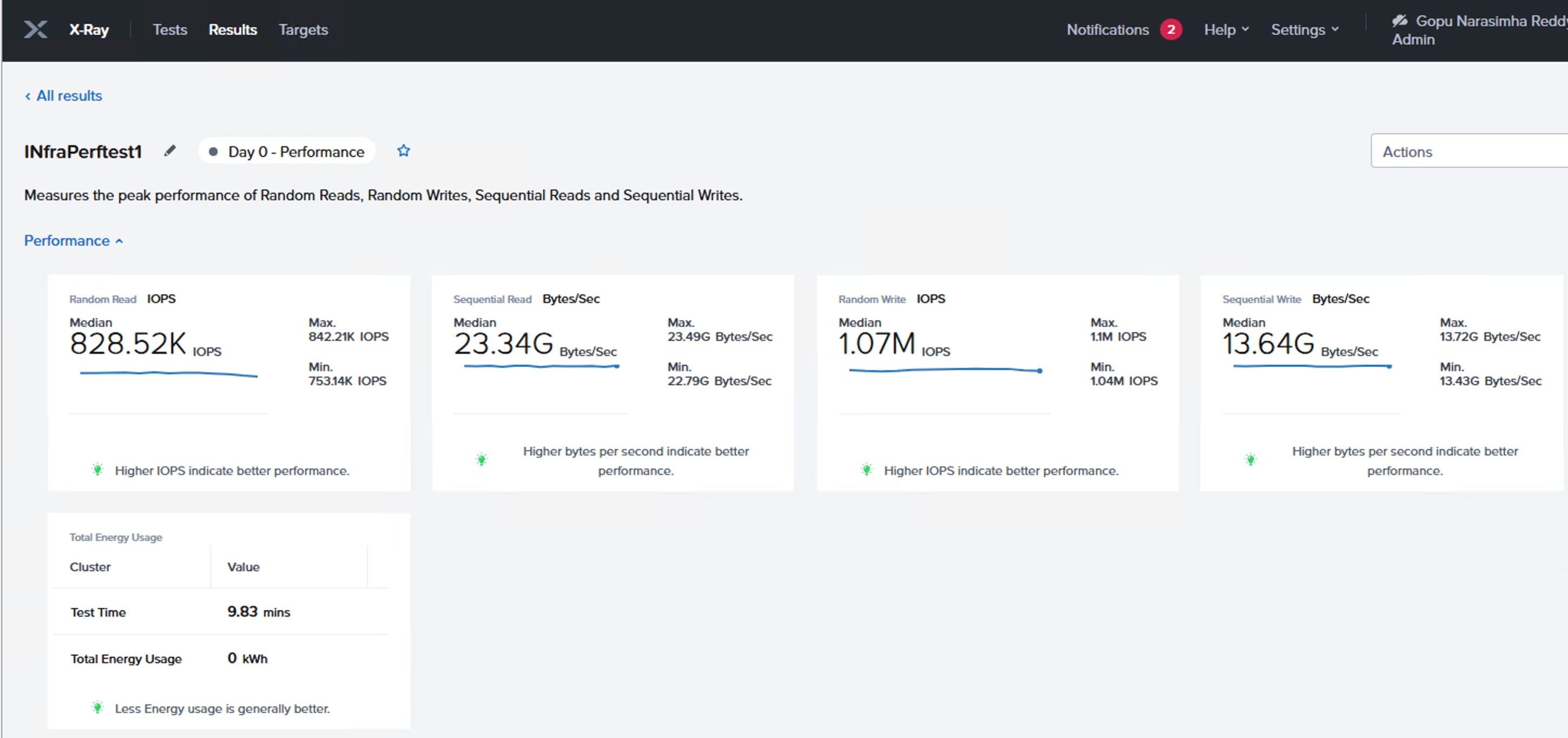
The following screenshot shows the random read IOPS and sequential read bandwidth for each VM hosted by the X-Ray tool. As shown, each VM is nearly delivering about 80,000 random reads and nearly 2.3GBps sequential read throughput.
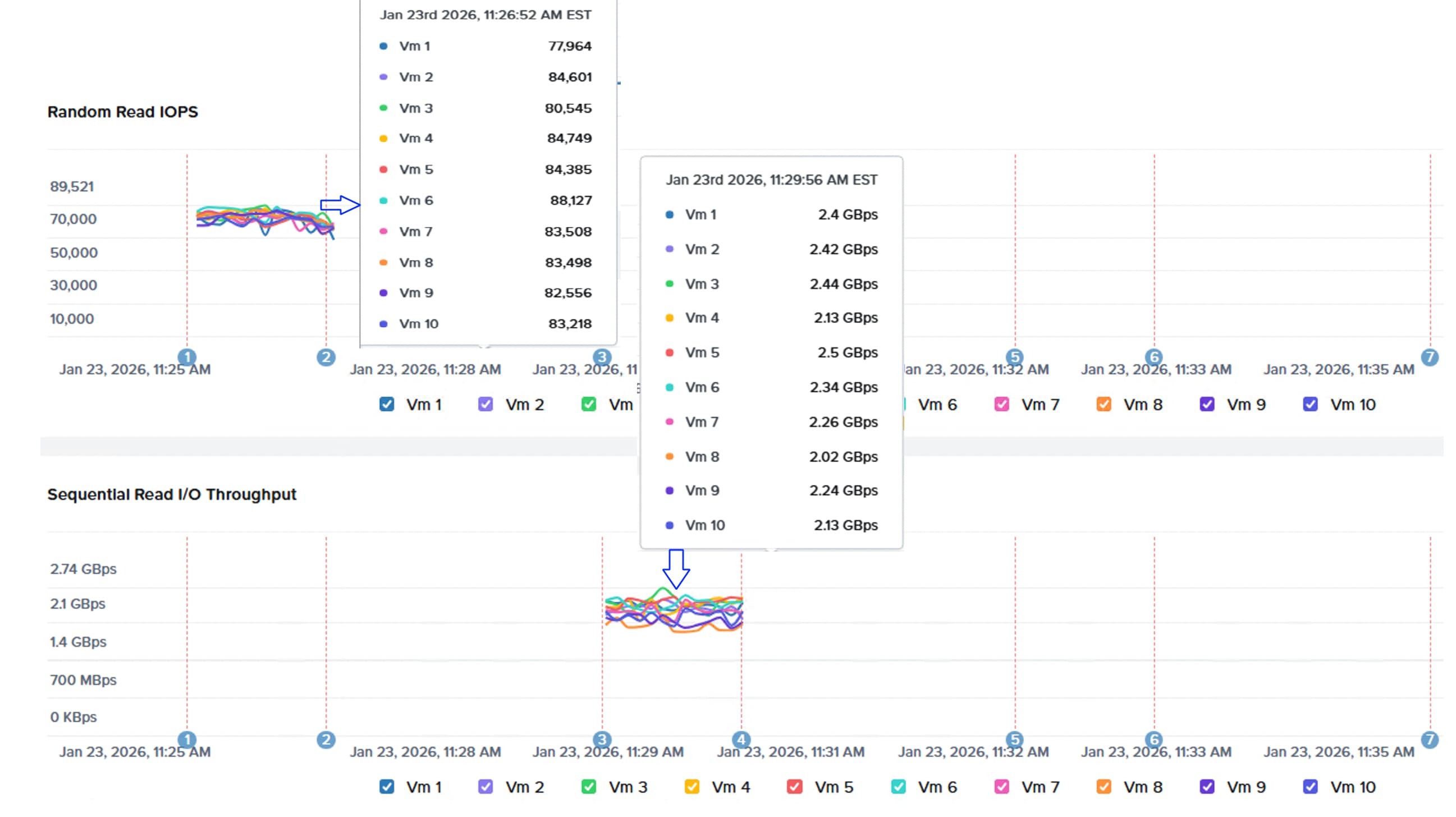
The following screenshot shows the random write IOPS and Sequential write bandwidth for each VM created by the X-Ray tool. As shown, each VM is nearly delivering about 100,000 random write and nearly 1.0 GBps sequential write throughput.
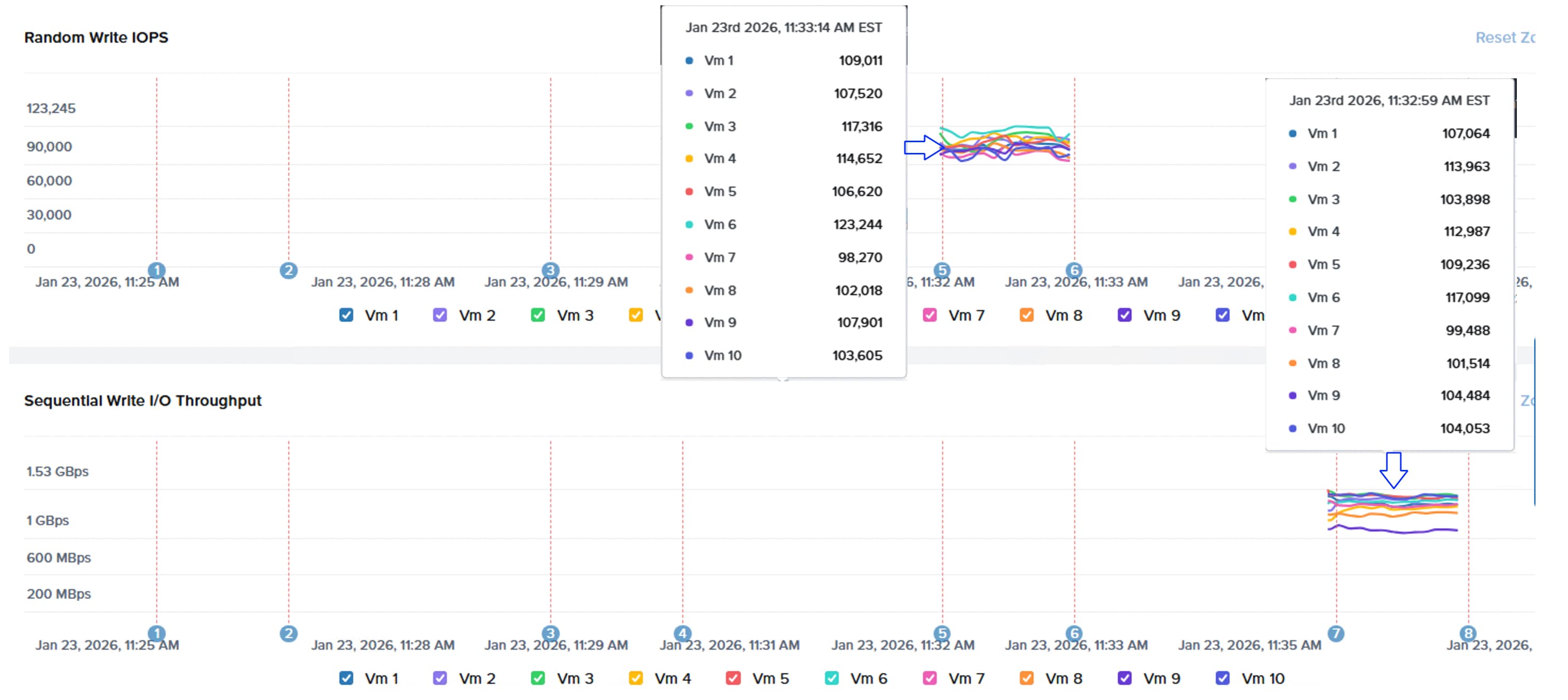
The following screenshot shows cpu utilization of all the AHV nodes and Controller VMs during the peak performance tests. Controller VM’s CPU utilization peaked to 100% utilization during random write test achieving nearly 1.1 million write IOPS.
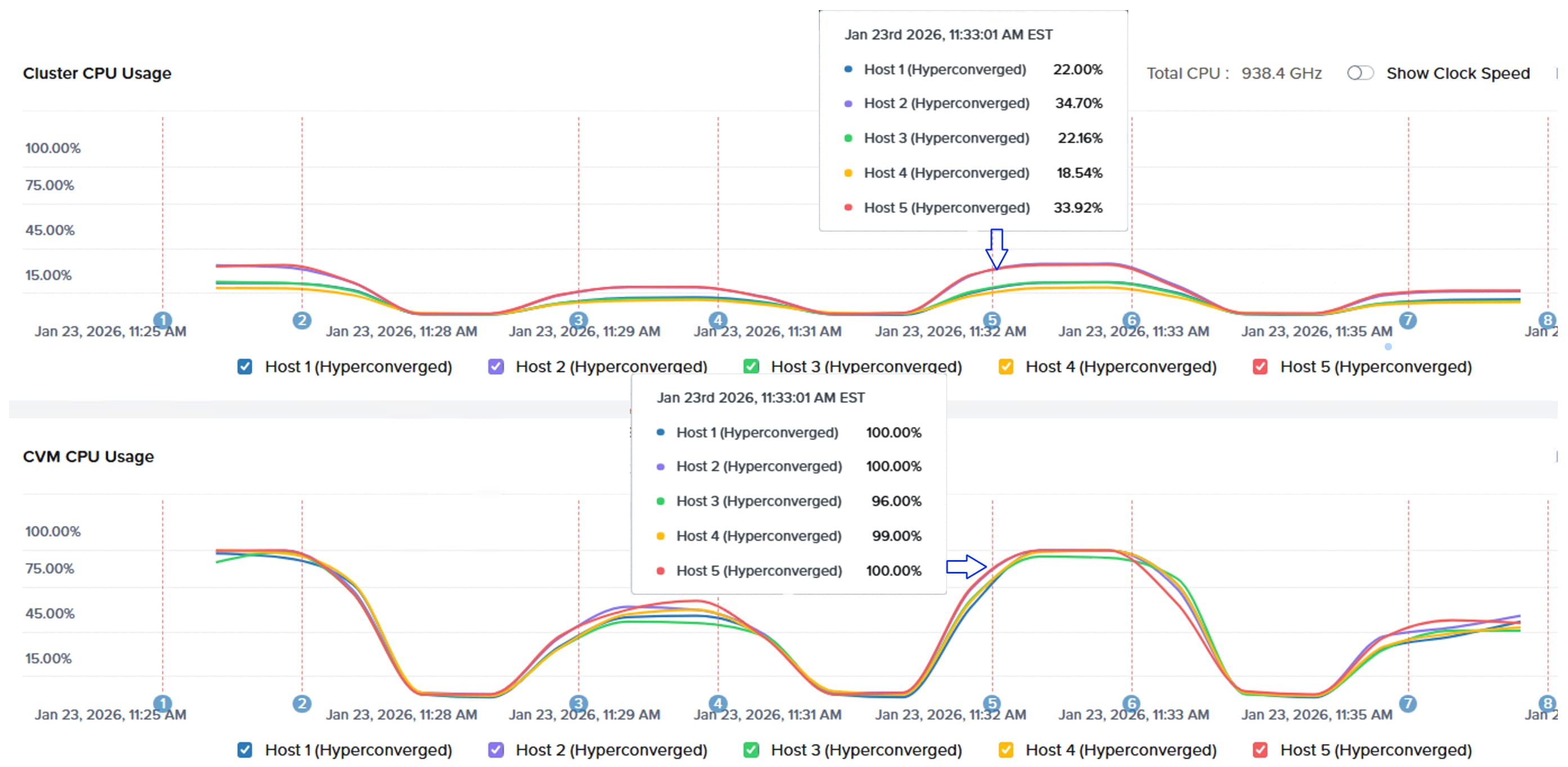
The following results shows the X-ray test results for M5/M6 based (brownfield deployment) NCI Compute Cluster backed with Pure Storage FlashArray. The Cluster has delivered nearly 840K random read IOPS and nearly 23.0GB/s sequential read bandwidth. Similarly, the cluster delivered 1.1 million random write IOPS and nearly 13.5 GB/s write throughput. The individual VM graphs for brownfield deployment cluster are consistent and in line with those displayed above. 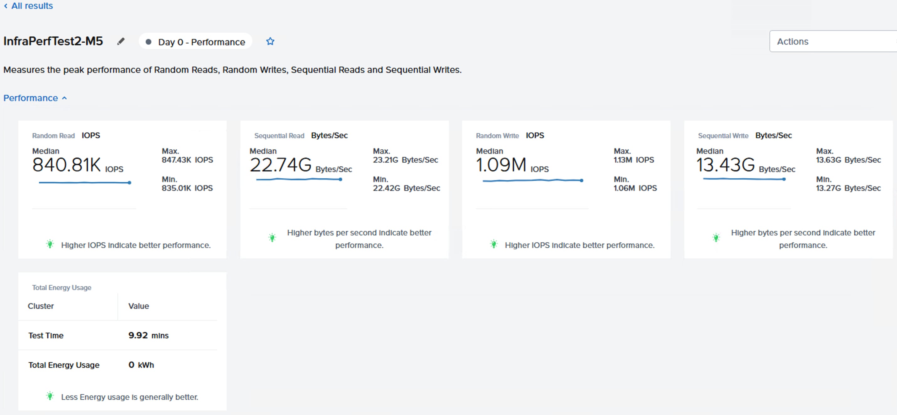
Both clusters delivered comparable storage performance during the storage stress tests, as they share the same FlashArray.
Note: The results shown above do not indicate the maximum performance capacity of the FlashArray connected to the cluster.
Migrate VMs to FlashStack using Nutanix Move
This chapter contains the following:
● Configure Compute Environments
Nutanix Move is a free, virtualization-agnostic mobility tool designed to migrate virtual machines (VMs) and workloads to Nutanix environments with minimal downtime. It supports cross-hypervisor migrations (e.g., VMware ESXi or Hyper-V to AHV) and cloud migrations (for example, AWS/Azure to NC2) through a user-friendly, automated interface. Nutanix Move is available for download on the Nutanix Support Portal. It can be deployed on ESXi or Nutanix clusters and accessed using either UI or CLI. For more details on deploying Nutanix Move, see Nutanix Move Deployment.
For more details on considerations and limitations on migrating virtual machines from ESXi to AHV environments, see the Nutanix Move User Guide.
Nutanix Move provides full migration support for some common operating systems, and data-only support for other operating systems. Unless otherwise specified, Nutanix has qualified most used 64-bit guest operating systems. Full migration support migrates the data, prepares the operating system with the required device drivers and scripts for retaining the IP addresses, and recreates the VM on a target cluster. For full migration support in Windows, the UAC must be disabled. Data-Only support migrates the data and recreates the VM on the target. Data-only support requires the user to install the appropriate VirtIO drivers to each of these VMs.
For this validation, Nutanix Move is deployed on Nutanix Cluster and accessed using GUI as shown below:
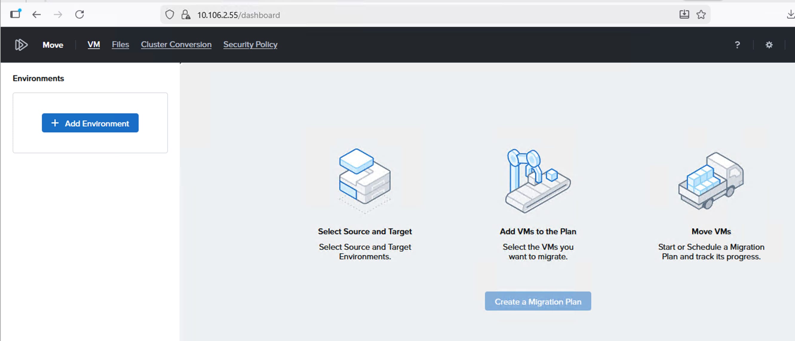
Two virtual machines (Windows Server 2022 VM and Red Hat Linux 9.5 VM), hosted on VMware vSphere 8.0 cluster have been selected and moved to Nutanix Cluster using Nutanix Move.
Configure Compute Environments
Procedure 1. Adding Compute Environments
Step 1. Add vCenter as the environment from which you would like to migrate the VMs. Click Add Environment and provide required details of your ESXi environment. After adding the ESXi environment, click the warning message that appears under the ESXi environment.
Note: VMware VDDK (Virtual Disk Development Kit) needs to be downloaded from Broadcom. For ESXi v8.0 you need download the VDDK-8.0.3.2 for ESXi v7.0 download VDDK-7.0.3.1.
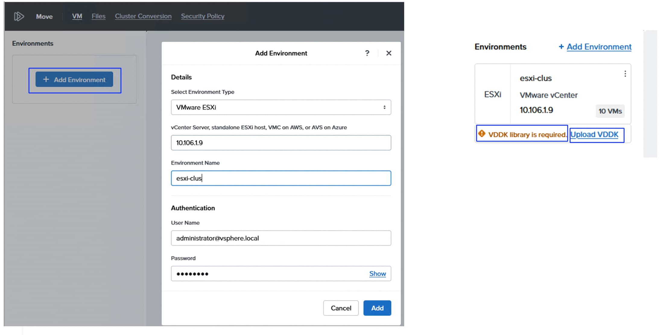
Step 2. After the required VDDK kit is downloaded, upload it to the Move as shown below:
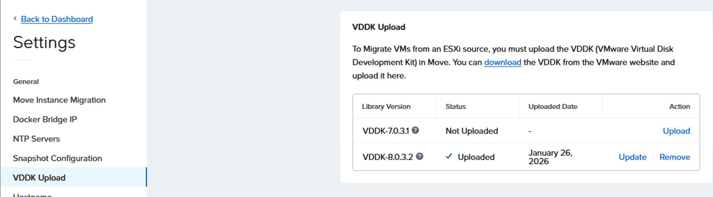
Step 3. To add the Nutanix Cluster, click Add Environment. You can enter the Prism Central that manages the target Nutanix cluster or the Prism element of the cluster. If Prism Central is used, an option to select the required target that the Prism Central manages displays.
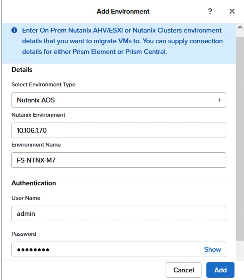
Step 4. Create the Migration Plan, click the link that appears on the right-side pane. Enter a name to the Migration Plan (ESXi-To-NuatxnixFlashStack) and click Proceed. Select the ESXi environment as Source and Nutanix cluster Target cluster. Select the Pure FlashArray that was added as external storage to the Nutanix Cluster and click Next.
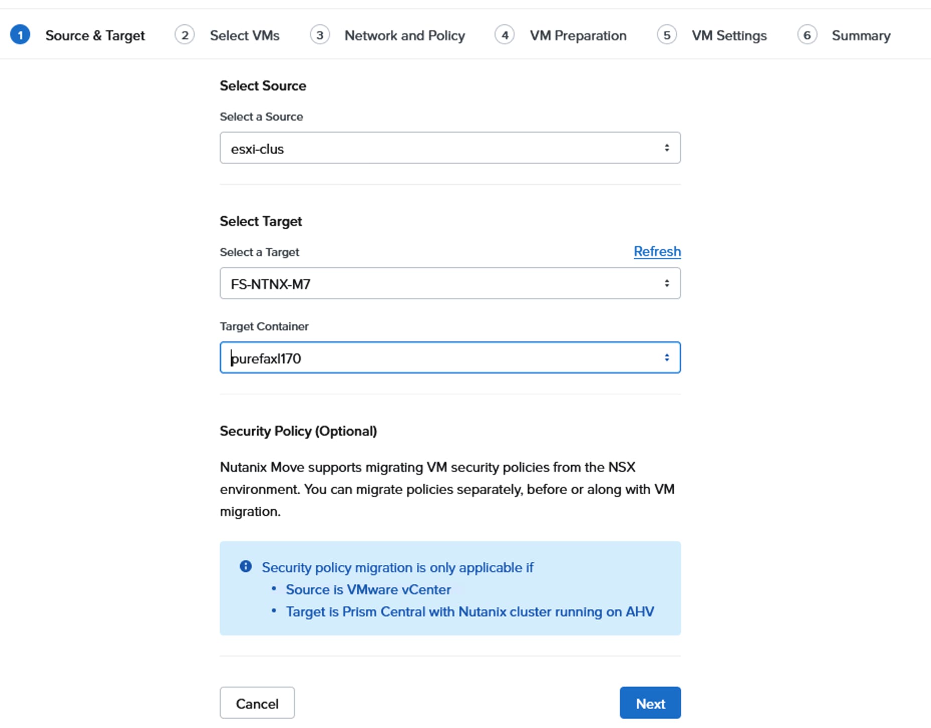
Step 5. From the Select VMs page, select the VMs that need to be migrated to Nutanix cluster and click Next. From the Network and Policy page, select the Target Network and click Next.
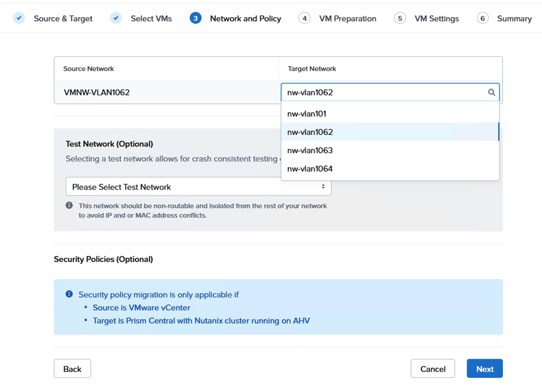
Step 6. From the VM Preparation page, select the Automatic preparation mode unless you want to prepare the virtual machine manually for the migration. As shown below, ensure to select the three check boxes which are essential for the successful migration of the VMs. Ensure the CD/DVD Drive is added to the VMs running on the ESXi environment. Once login credentials for each VM are entered, click Next. Ensure the credentials you provide have admin rights for successful removal and installation of guest drivers.
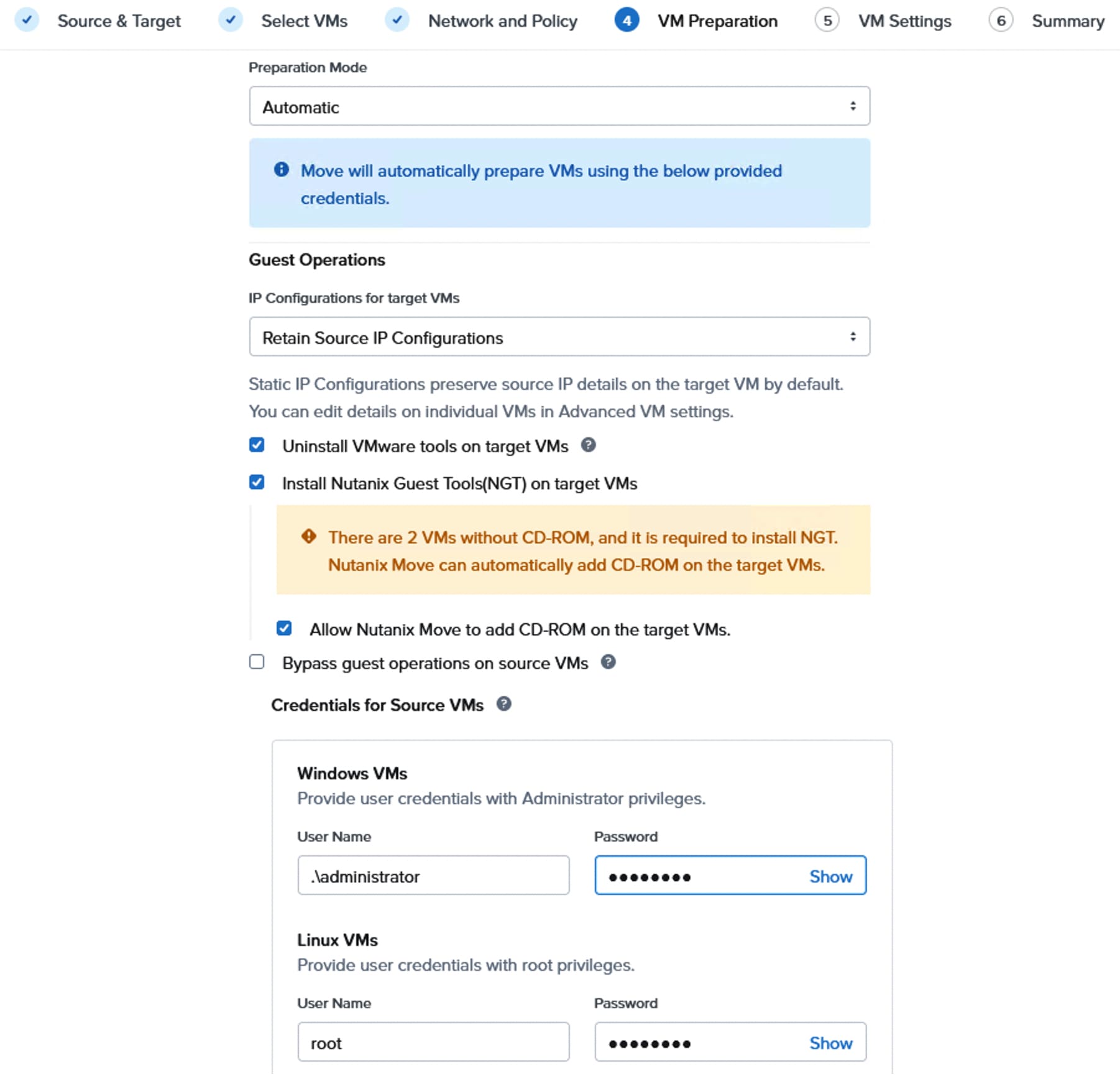
Step 7. From the VM Settings page, ensure to check the Retain MAC address option and click Next. To change the VM configuration individually, click Change Setting and do the required changes for VMs that are going to be created on the Target cluster. Click Next. Review the Summary of the migration and click Save and Start to start the migration immediately.
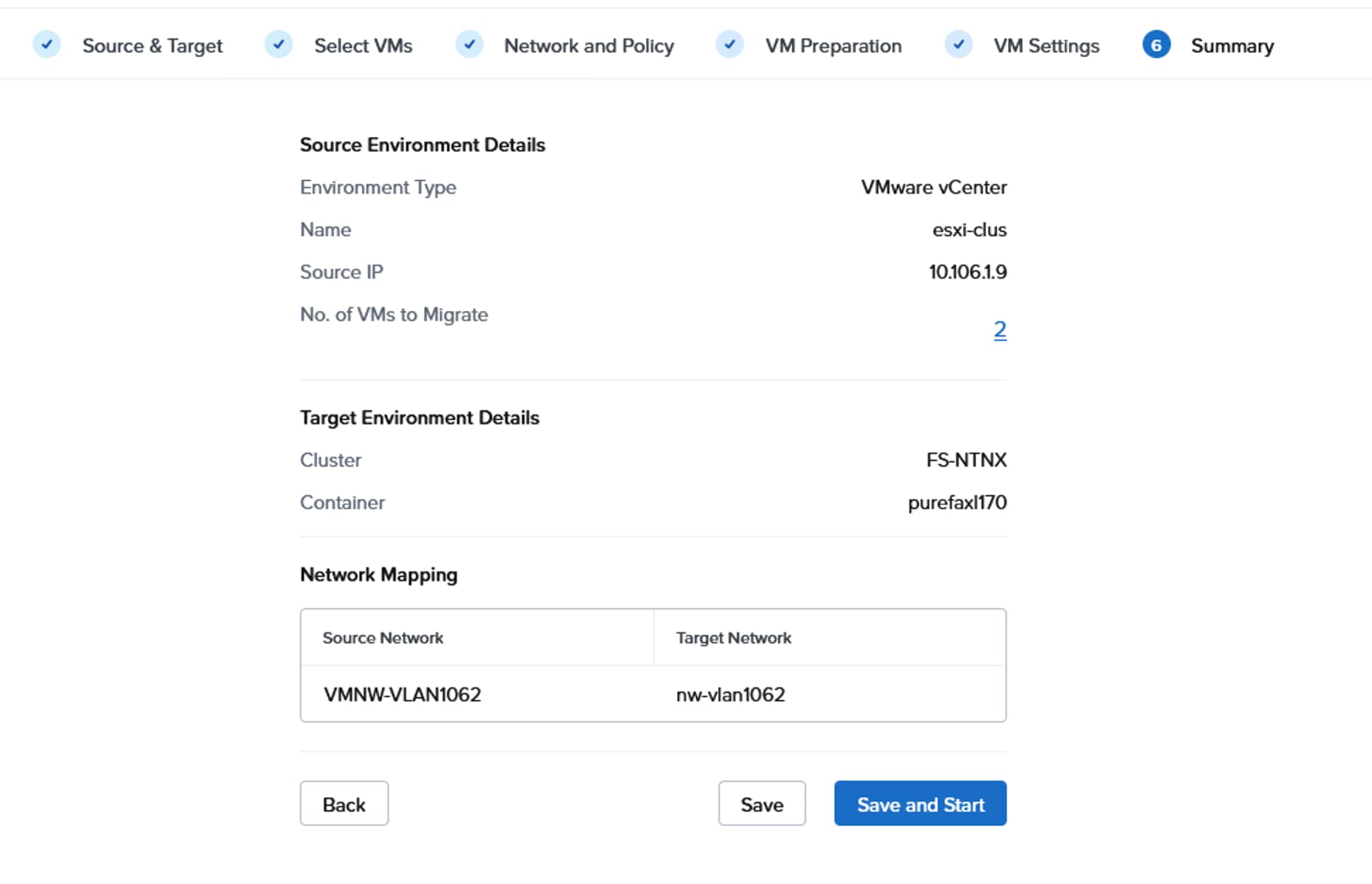
Step 8. The migration plan will be validated and output error details for any issues with the plan. Click Edit to edit the plan and fix the issues. Once issues are fixed, it goes to In-Progress state and waits at the Cutover stage.
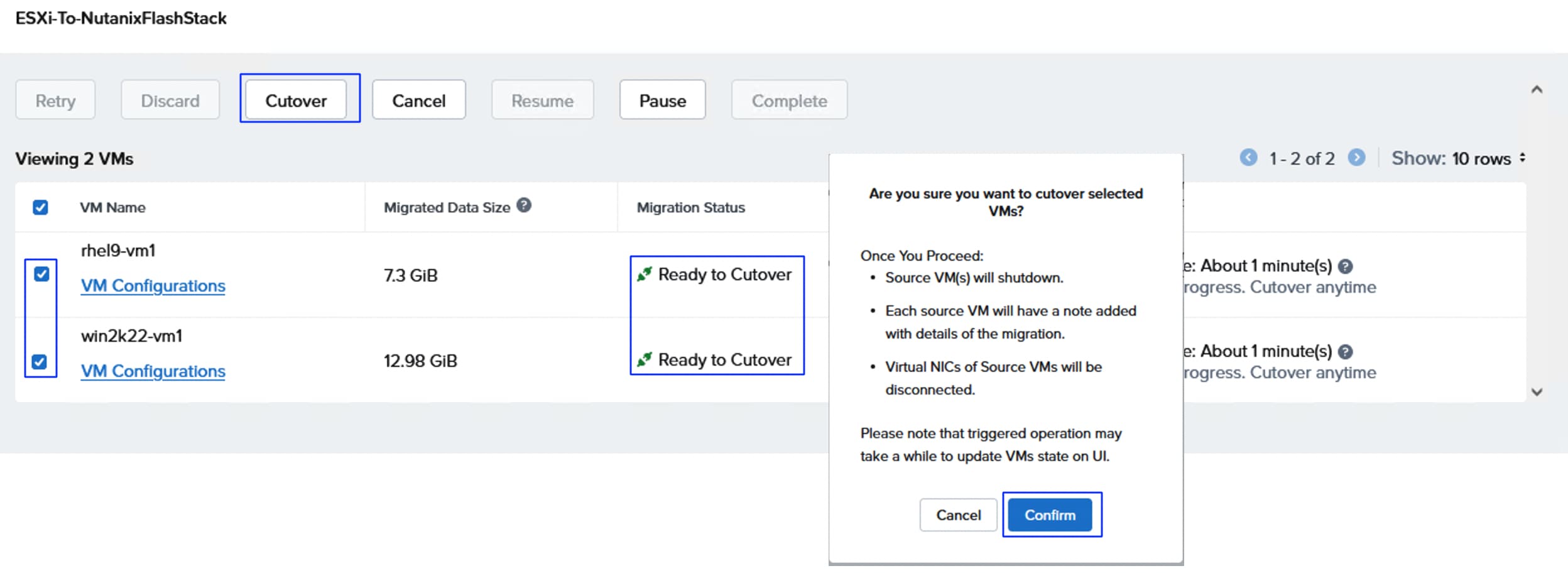
Step 9. Select both VMs, click Cutover, and then click Confirm to start the cutover process. The VMs are migrated to the target cluster. Ensure that the VMs are powered on and accessible using the same old IPs.
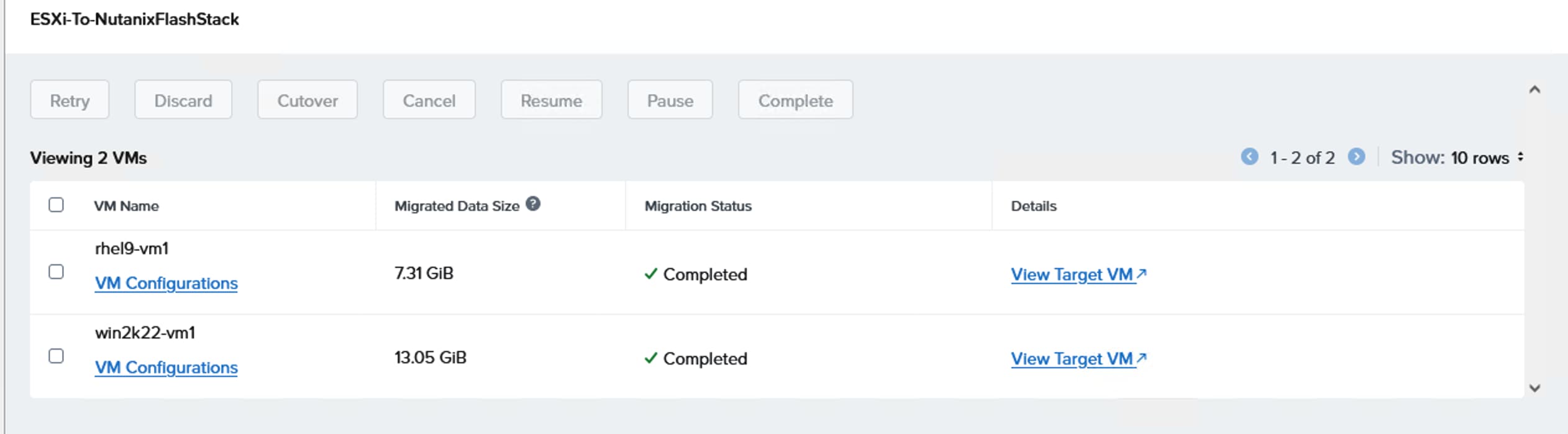
The migration plan successfully completed:
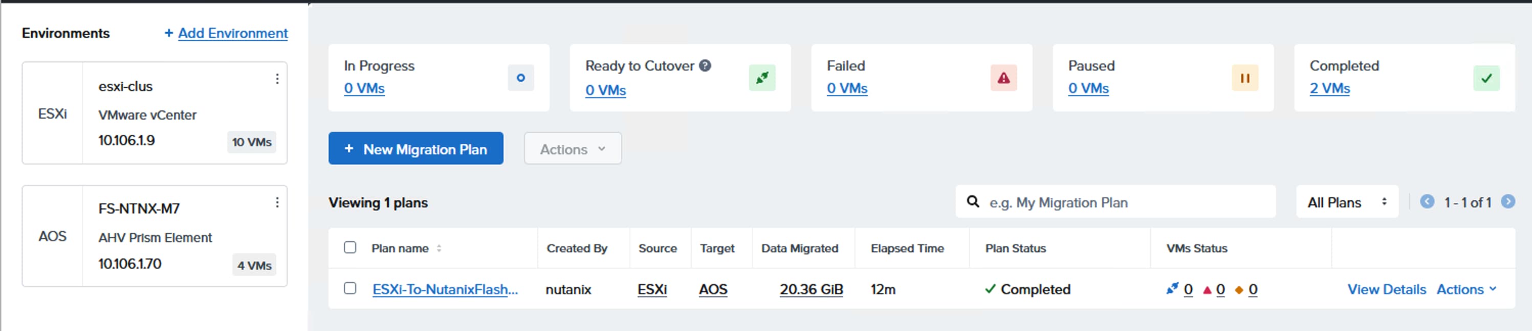
As previously discussed, AOS delegates these operations to the external storage but present them to the administrator as standard Nutanix VM-Level operations. You can take snapshot of VM using either Prism Element or Prism Central.
Procedure 1. SnapShot and clone a VM
Step 1. To take snapshot of a VM using Prism Element. Log into PE and select the VM page from the drop-down list. Select the VM and click Take Snapshot. Enter a name for the snapshot and click Submit.
Step 2. To restore the VM from the snapshot, click VM Snapshots and select the snapshot you want to restore and click Restore.
Step 3. After Restore from the snapshot, power on the VM and verify if your data is recovered.
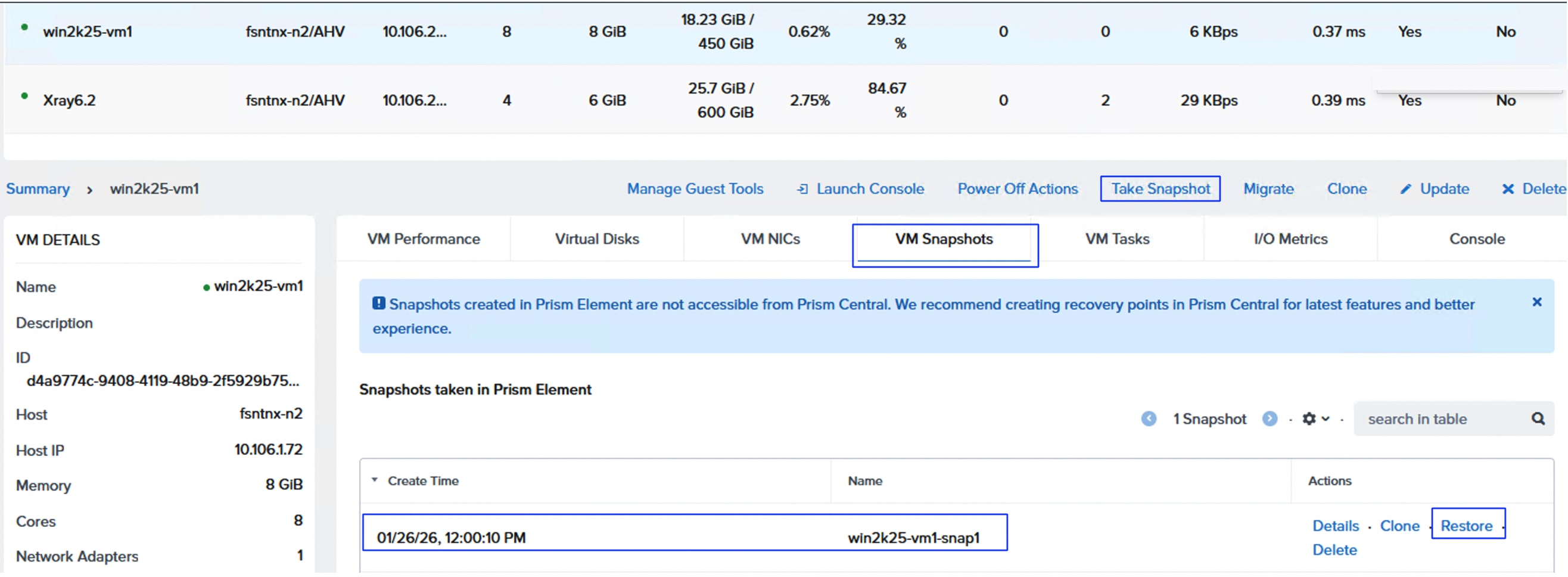
For more details on the Nutanix Snapshot behavior with Pure Storage FlashArray, go to: Nutanix Snapshots with Pure Storage
Step 4. To clone an existing VM, select the VM and right-click the VM and select the Clone option. Enter a name for the new VM that is cloned from the existing VM and change the settings if required then click Clone. A new VM will be created with the name you entered. Power on the VM and change the IP address of the VM if DHCP is not used.
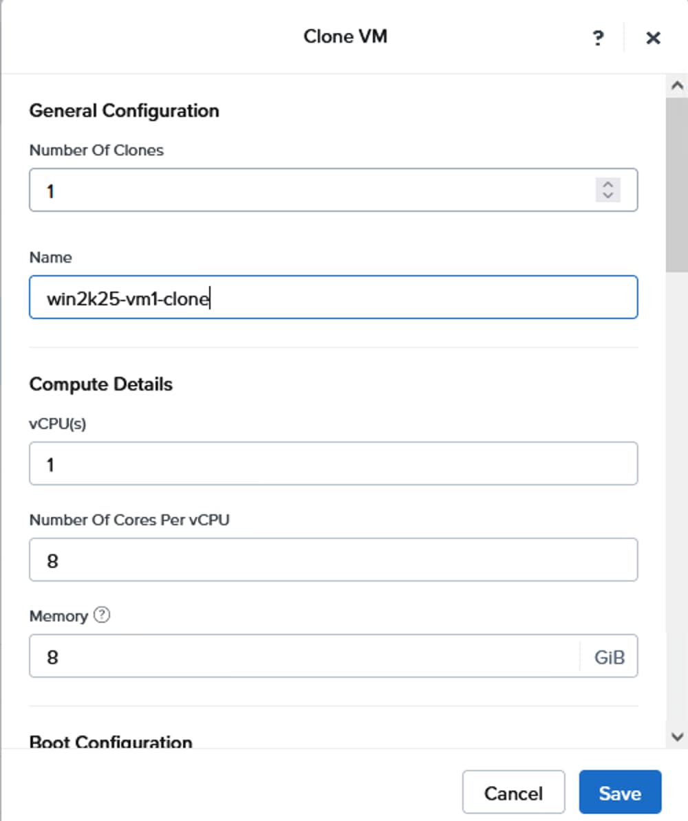
About the authors
Gopu Narasimha Reddy, Technical Marketing Engineer, Cisco Systems, Inc.
Gopu Narasimha Reddy is a Technical Marketing engineer with the UCS Solutions team at Cisco. He is currently focused on validating and developing Cisco UCS infrastructure solutions for enterprise workloads with different operating environments including Windows, Nutanix, VMware, Linux, and OpenShift. Gopu is also involved in publishing database benchmarks on Cisco UCS servers. His areas of interest include building and validating reference architectures, and development of sizing tools in addition to assisting customers in database deployments
Acknowledgements
For their support and contribution to the design, validation, and creation of this Cisco Validated Design, the authors would like to thank:
● Chris O’Brien, Senior Director, Technical Marketing, Cisco Systems, Inc.
● Rupesh Chakkingal, Director Product Management, Cisco Systems, Inc.
● Jeff Mercier, Engineering Product Manager, Cisco Systems, Inc.
● Brian Everitt, Technical Marketing Engineer, Cisco Systems, Inc.
● Simranjit Singh, Solutions Architect, Pure Storage Inc.
● Craig Waters, Solutions Director, Pure Storage Inc.
Appendix
This appendix contains the following:
● Appendix B - References used in this guide
This section defines the terms used in this guide.
AOS vDisk: Every AOS vDisk is a volume on Pure Storage FlashArray.
Nutanix Cloud Infrastructure - Compute (NCI-C) - A Nutanix NCI compute cluster construct that is created using the supported industry-standard servers which consumes storage from the connected Pure Storage FlashArray.
Nutanix Cloud Platform (NCP): A hyperconverged platform that consolidates computing, storage, and networking into a unified pool. It uses AOS for storage, AHV for virtualization, and Prism Central for centralized management across environments. In an NCP with Pure Storage FlashArray setup, the NCI compute cluster provides functionalities such as AHV virtualization, networking micro segmentation management in the AHV vSwitches using Nutanix Flow, security configuration, and disaster recovery.
Prism Central: A centralized platform to monitor and manage multiple Nutanix clusters and apps.
Prism Element: A service already built into the Nutanix platform to manage a deployed Nutanix cluster. Prism Element provides the ability to fully configure, manage, and monitor Nutanix clusters running AHV. Prism Element can only manage its associated cluster.
Nutanix AHV: The native bare-metal type-1 hypervisor for the Nutanix solution that enables you to unbox a Nutanix system and immediately start deploying VMs with enterprise-class virtualization capabilities.
Nutanix Controller VM (CVM): A storage engine in Nutanix AOS that exists on every node in the Nutanix Cloud Infrastructure (NCI) compute cluster. It orchestrates critical data services to manage distributed file systems, such as handling user I/O, data placement, and metadata management while ensuring data integrity and availability.
Nutanix Foundation: An official deployment software of Nutanix that allows you to configure a pre-imaged node, or image a node with a hypervisor and an AOS of your choice. Foundation also allows you to form a cluster out of nodes whose hypervisor and AOS versions are the same, with or without re-imaging.
Nutanix Foundation Central: A Nutanix software that allows you to create clusters from factory-imaged nodes and remotely reimage existing nodes that are already registered with Foundation Central from Prism Central.
Pure Storage Controller: A disk controller or storage processor that manages the flow of data between the compute cluster and the external Pure Storage FlashArray. It also provides functionalities such as efficient and organized data storage, cache management, logical volumes management, and monitoring and reporting of the storage device performance. For more information
Purity: The operating system that manages the data in the external Pure storage and provides the data services for the applications, along with data mobility.
Realm: A logical construct to group storage objects together and deliver multi-tenancy. The realm defines the QoS policies, resource limits, users, network interfaces (either physical or VLAN interfaces), and volumes in a Pure Storage FlashArray. A Pure Storage FlashArray administrator can create a realm.
Pod: A logical containment of storage objects like volumes or file systems that is created on Pure Storage FlashArray within a realm.
Appendix B – References used in this guide
Cisco
Cisco Intersight: https://www.intersight.com
Cisco Intersight Private Virtual Appliance: https://intersight.com/help/appliance/whats_new/private_appliance/2020
Cisco Intersight Connected Virtual Appliance: https://www.cisco.com/c/en/us/td/docs/unified_computing/Intersight/b_Cisco_Intersight_Appliance_Getting_Started_Guide/m_appliance_overview.html
Cisco UCS Hardware and Software Compatibility: https://ucshcltool.cloudapps.cisco.com/public/
FlashStack with Nutanix Field Installation Guide: https://community.cisco.com/t5/unified-computing-system-knowledge-base/cisco-flashstack-with-nutanix-installation-field-guide/ta-p/5353574
Nutanix
Nutanix Compatibility Matrix: https://portal.nutanix.com/page/compatibility-interoperability-matrix
FlashStack with Nutanix Compatibility: https://portal.nutanix.com/page/documents/details?targetId=Cisco-UCS-Compute-HW-FW-Compatibility:cis-compute-hfcl-intro-r.html
Nutanix Cloud Platform with Pure Storage FlashArray: https://portal.nutanix.com/page/documents/details?targetId=Nutanix-Cloud-Platform-with-Pure-Storage-Deployment-Guide:Nutanix-Cloud-Platform-with-Pure-Storage-Deployment-Guide
Nutanix portal Download List: https://portal.nutanix.com/page/downloads/list
Nutanix Upgrade Paths: https://portal.nutanix.com/page/documents/upgrade-paths
Nutanix Supported Guest Operating Systems: https://portal.nutanix.com/page/compatibility-interoperability-matrix/guestos/compatibility
Pure Storage
Pure Storage Nutanix Platform Guide: https://support.purestorage.com/bundle/m_nutanix/page/Solutions/Nutanix/topics/c_nutanix.html
FlashStack: https://flashstack.com
Pure Storage FlashArray//X: https://www.purestorage.com/products/unified-block-file-storage/flasharray-x.html
Pure Storage FlashArray//XL: https://www.purestorage.com/products/unified-block-file-storage/flasharray-xl.html
Pure Storage FlashArray//C: https://www.purestorage.com/products/unified-block-file-storage/flasharray-c.html
Pure Storage FlashStack Compatibility Matrix. This interoperability list will require a support login from Pure: https://support.purestorage.com/bundle/m_product_information/page/FlashStack/Product_Information/topics/reference/r_flashstack_compatibility_matrix.html
CVD Program
ALL DESIGNS, SPECIFICATIONS, STATEMENTS, INFORMATION, AND RECOMMENDATIONS (COLLECTIVELY, "DESIGNS") IN THIS MANUAL ARE PRESENTED "AS IS," WITH ALL FAULTS. CISCO AND ITS SUPPLIERS DISCLAIM ALL WARRANTIES, INCLUDING, WITHOUT LIMITATION, THE WARRANTY OF MERCHANTABILITY, FITNESS FOR A PARTICULAR PURPOSE AND NONINFRINGEMENT OR ARISING FROM A COURSE OF DEALING, USAGE, OR TRADE PRACTICE. IN NO EVENT SHALL CISCO OR ITS SUPPLIERS BE LIABLE FOR ANY INDIRECT, SPECIAL, CONSEQUENTIAL, OR INCIDENTAL DAMAGES, INCLUDING, WITHOUT LIMITATION, LOST PROFITS OR LOSS OR DAMAGE TO DATA ARISING OUT OF THE USE OR INABILITY TO USE THE DESIGNS, EVEN IF CISCO OR ITS SUPPLIERS HAVE BEEN ADVISED OF THE POSSIBILITY OF SUCH DAMAGES.
THE DESIGNS ARE SUBJECT TO CHANGE WITHOUT NOTICE. USERS ARE SOLELY RESPONSIBLE FOR THEIR APPLICATION OF THE DESIGNS. THE DESIGNS DO NOT CONSTITUTE THE TECHNICAL OR OTHER PROFESSIONAL ADVICE OF CISCO, ITS SUPPLIERS OR PARTNERS. USERS SHOULD CONSULT THEIR OWN TECHNICAL ADVISORS BEFORE IMPLEMENTING THE DESIGNS. RESULTS MAY VARY DEPENDING ON FACTORS NOT TESTED BY CISCO.
CCDE, CCENT, Cisco Eos, Cisco Lumin, Cisco Nexus, Cisco StadiumVision, Cisco TelePresence, Cisco WebEx, the Cisco logo, DCE, and Welcome to the Human Network are trademarks; Changing the Way We Work, Live, Play, and Learn and Cisco Store are service marks; and Access Registrar, Aironet, AsyncOS, Bringing the Meeting To You, Catalyst, CCDA, CCDP, CCIE, CCIP, CCNA, CCNP, CCSP, CCVP, Cisco, the Cisco Certified Internetwork Expert logo, Cisco IOS, Cisco Press, Cisco Systems, Cisco Systems Capital, the Cisco Systems logo, Cisco Unified Computing System (Cisco UCS), Cisco UCS B-Series Compute Node Servers, Cisco UCS C-Series Rack Servers, Cisco UCS S-Series Storage Servers, Cisco UCS X-Series, Cisco Intersight, Cisco UCS Management Software, Cisco Unified Fabric, Cisco Application Centric Infrastructure, Cisco Nexus 9000 Series, Cisco Nexus 7000 Series. Cisco Prime Data Center Network Manager, Cisco NX-OS Software, Cisco MDS Series, Cisco Unity, Collaboration Without Limitation, EtherFast, EtherSwitch, Event Center, Fast Step, Follow Me Browsing, FormShare, GigaDrive, HomeLink, Internet Quotient, IOS, iPhone, iQuick Study, LightStream, Linksys, MediaTone, MeetingPlace, MeetingPlace Chime Sound, MGX, Networkers, Networking Academy, Network Registrar, PCNow, PIX, PowerPanels, ProConnect, ScriptShare, SenderBase, SMARTnet, Spectrum Expert, StackWise, The Fastest Way to Increase Your Internet Quotient, TransPath, WebEx, and the WebEx logo are registered trade-marks of Cisco Systems, Inc. and/or its affiliates in the United States and certain other countries. (LDW_P4)
All other trademarks mentioned in this document or website are the property of their respective owners. The use of the word partner does not imply a partnership relationship between Cisco and any other company. (0809R)