Splunk POD: A Turn-Key Solution for Cisco UCS Infrastructure and Splunk Deployment Guide
Available Languages
Bias-Free Language
The documentation set for this product strives to use bias-free language. For the purposes of this documentation set, bias-free is defined as language that does not imply discrimination based on age, disability, gender, racial identity, ethnic identity, sexual orientation, socioeconomic status, and intersectionality. Exceptions may be present in the documentation due to language that is hardcoded in the user interfaces of the product software, language used based on RFP documentation, or language that is used by a referenced third-party product. Learn more about how Cisco is using Inclusive Language.
- US/Canada 800-553-2447
- Worldwide Support Phone Numbers
- All Tools
 Feedback
 Feedback
Published: May 2026
About the Cisco Validated Design Program
The Cisco Validated Design (CVD) program consists of systems and solutions designed, tested, and documented to facilitate faster, more reliable, and more predictable customer deployments. For more information, go to: https://www.cisco.com/go/designzone
Executive Summary
Splunk POD is an integrated hardware and software solution that combines Cisco UCS servers, Cisco Nexus switches, Cisco Intersight, and Splunk Enterprise platform to deliver an "appliance-like" on-premises deployment experience. This document provides technical guidance for physically connecting the hardware, further configuring servers in Cisco Intersight, and installing the operating system to prepare them to operate as a cluster for Splunk POD.
Key Features
● Predictable Performance: Cisco-validated S/M/L bundles ensure consistent performance
● Simplified Deployment: Kubernetes-based automation reduces deployment time from weeks to hours
● Unified Support: Single vendor support for entire hardware and software stack
● Enhanced Security: Optional Enterprise Security (ES) integration for advanced threat detection
Solution Overview
This chapter contains the following:
● Audience
Splunk POD is a turnkey solution that includes:
● Splunk Kubernetes Installer
● Splunk Enterprise platform running in Kubernetes (SOK) created with the Kubernetes Installer for Splunk POD
● Cisco UCS servers (Cisco UCS C225 and Cisco UCS C245 models)
● Cisco Nexus 9000 switches
● Cisco Intersight management
● Optional: Splunk Enterprise Security (ES)
The intended audience for this document includes, but is not limited to, sales engineers, field consultants, professional services, IT managers, IT engineers and IT architects, partners, and customers who are interested in deploying Splunk POD.
This document provides a step-by-step guide to configure and prepare the hardware for Splunk POD. This guide explains the host, network, and rack configuration requirements.
Splunk POD offers 3 pre-defined sizing options to meet the needs of different size organizations (Table 1).
| Size |
Max Daily Ingest |
Use Case |
Hardware Profile |
| Small |
500 GB/day |
Department/Small Enterprise |
12-13 nodes |
| Medium |
1 TB/day |
Mid-size Enterprise |
15-16 nodes |
| Large |
2.5 TB/day |
Large Enterprise |
19-20 nodes |
| Extra-Large |
10 TB/day |
Very-large Enterprise |
34-37 nodes |
Data Retention Requirements for Small, Medium, and Large:
● 90 days in hot/warm cache (local storage)
● 1-year total retention (SmartStore)
● 3 copies (replicas) of data stored in SmartStore to prevent data loss
Data Retention Requirements for Extra-Large:
● 60 days in hot/warm cache (local storage)
● 180 days in total retention (SmartStore)
● 3 copies (replicas) of data stored in SmartStore
Some of the key benefits of Splunk POD include:
● Simplified Management and Deployment: Splunk POD combines the ease of server management provided by Cisco Intersight with the UCS platform for automated hardware configuration and deployment with the power of Kubernetes and the Splunk Operator for Kubernetes to provide rapid and simplified deployment. Using POD’s Kubernetes Installer, Splunk can be automatically configured and deployed in about 20 minutes from host/OS configuration using pre-configured specifications that match the POD hardware.
● High Availability and Reliability: Splunk POD focuses on providing resiliency to customer deployments with hardware and software redundancies. The power of Kubernetes allows self-healing and protection against outages.
● Real Time Insights and Proactive Monitoring: Using a combination of technologies, Intersight, Splunk, and other open-source tools, Splunk POD provides visibility into the health of the cluster.
● Accelerated Deployment and Reduced Risk: Validated reference architectures and Cisco Validated Designs (CVDs) provide prescriptive, step-by-step guidance for deploying Splunk Enterprise on Cisco UCS, accelerating time-to-value, and minimizing deployment risks
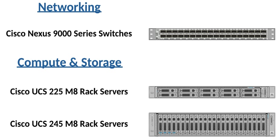
This architecture for running Splunk Enterprise on Cisco UCS uses the following infrastructure components for compute, network, and storage:
● Cisco UCS Nexus 9000 Switches
● Cisco UCS C-Series M8 Series C225 and Cisco UCS C245 Rack Servers
Splunk POD servers can be divided into two categories, with additional server types in each category, depending on server role.
Control Plane: Control Plane services consist of Cisco UCS C225 servers:
● Bastion: A Cisco UCS C225 server that hosts the Kubernetes Installer for Splunk POD as well as the Splunk Deployment server.
● Controllers: Three Cisco UCS C225 servers that host the Kubernetes Control Plane services and the local OCI image registries used by the cluster.
Workers: Workers host the Kubernetes workloads. Apart from the Splunk Agent Management service, all Splunk services are deployed on these machines:
● Search Heads: Cisco UCS C225 servers sized to support Splunk Search workloads.
● Indexers: Cisco UCS C245 servers with local NVMe storage to support the deployment of Splunk Indexers with sufficient cache to store at least 60 days of data in local cache.
● Volume Servers: Cisco UCS C245 servers with ultra-dense local storage designed to host at least 180 days of data in S3-compliant storage.
Technology Overview
This chapter contains the following:
● Cisco Unified Computing System
Cisco Unified Computing System
Cisco Unified Computing System (Cisco UCS) is a next-generation data center platform that integrates computing, networking, storage access, and virtualization resources into a cohesive system designed to reduce total cost of ownership and increase business agility.
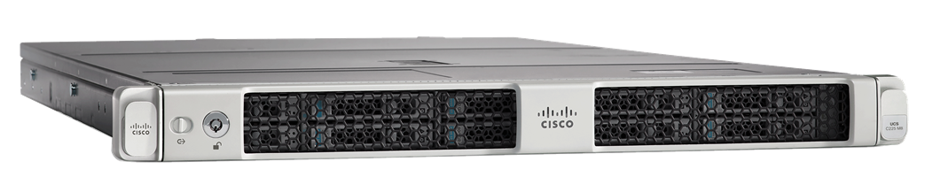
Cisco UCS C225 M8 Rack Server
The Cisco UCS C225 M8 Rack Server is a versatile general-purpose infrastructure and application server. This high-density, 1RU, single-socket rack server delivers industry-leading performance and efficiency for a wide range of workloads, including virtualization, collaboration, and bare-metal applications. The Cisco UCS C225 M8 Rack Server extends the capabilities of the Cisco UCS Rack Server portfolio. It powers 5th Gen and 4th Gen AMD EPYC Processors with 150 percent more cores per socket designed using AMD’s chiplet architecture. With advanced features such as AMD Infinity Guard, compute-intensive applications will see significant performance improvements and reap other benefits such as power and cost efficiencies.
You can deploy the Cisco UCS C-Series Rack Servers as standalone servers or as part of the Cisco Unified Computing System managed by Cisco Intersight or Cisco UCS Manager to take advantage of Cisco standards-based unified computing innovations that can help reduce your Total Cost of Ownership (TCO) and increase your business agility.
The Cisco UCS C225 M8 Rack Server brings many new innovations to the Cisco UCS AMD Rack Server portfolio. With the introduction of PCIe Gen 5.0 for high-speed I/O, a DDR5 memory bus, and expanded storage capabilities, the server delivers significant performance and efficiency gains that will improve your application performance. For more details, go to: https://www.cisco.com/c/en/us/products/collateral/servers-unified-computing/ucs-c-series-rack-servers/ucs-c225-m8-rack-server-ds.html
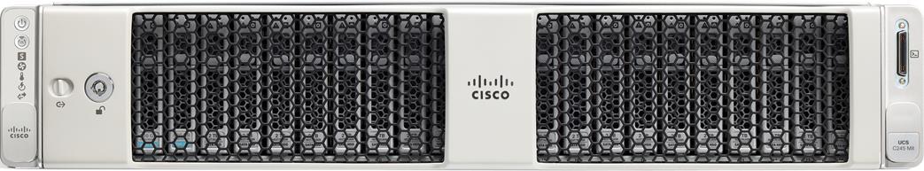
Cisco UCS C245 M8 Rack Server
The Cisco UCS C245 M8 Rack Server is perfectly suited for a wide range of storage and I/O-intensive applications such as big data analytics, databases, collaboration, virtualization, consolidation, AI/ML, and high-performance computing supporting up to two AMD CPUs in a 2RU form factor.
The Cisco UCS C245 M8 Rack Server extends the capabilities of the Cisco UCS Rack Server portfolio. It powers 5th Gen and 4th Gen AMD EPYC Processors with up to 160 cores per socket designed using AMD’s chiplet architecture. With advanced features like AMD Infinity Guard, compute-intensive applications will see significant performance improvements and will reap other benefits such as power and cost efficiencies.
Cisco UCS C245 M8 Rack Servers can be deployed as part of a Cisco UCS–managed environment, through Cisco Intersight, or standalone. When used in combination with Cisco Intersight, the Cisco UCS C245 M8 brings the power and automation of unified computing to enterprise applications, including Cisco Single Connect technology, drastically reducing switching and cabling requirements.
For more information, go to: https://www.cisco.com/c/en/us/products/collateral/servers-unified-computing/ucs-c-series-rack-servers/ucs-c245-m8-rack-server-ds.html
Splunk Enterprise is a software product that enables you to search, analyze, and visualize the data gathered from the components of your IT infrastructure or business. Splunk Enterprise collects data from any source, including metrics, logs, clickstreams, sensors, stream network traffic, web servers, custom applications, hypervisors, containers, social media, and cloud services. It enables you to search, monitor and analyze that data to discover powerful insights across multiple use cases like security, IT operations, application delivery and many more. With Splunk Enterprise, everyone from data and security analyst to business users can gain insights to drive operational performance and business results. Splunk makes it easy to input data from virtually any source — without the limitations of database structures.
Splunk POD runs Splunk Enterprise in Kubernetes via the Splunk Operator for Kubernetes (SOK). SOK provides a scalable, Kubernetes-native solution for deploying and managing Splunk Enterprise. It leverages custom resource objects to streamline operations and ensure high availability.
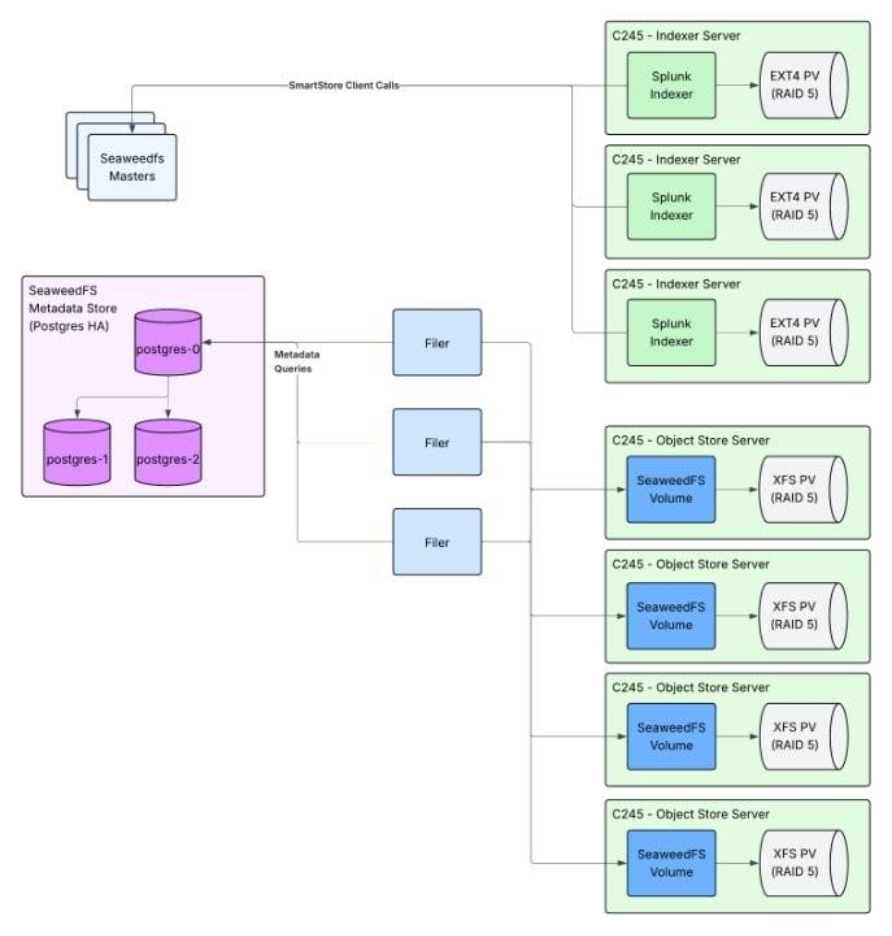
SeaweedFS is an S3-compatible distributed storage system for blobs, objects, files and more. Splunk POD utilizes SeaweedFS for the Splunk Operator for Kubernetes app framework and for Splunk SmartStore. It is a separate storage component from Splunk indexer storage. SeaweedFS follows a simple architecture. It is composed of a master server which coordinates volume management and metadata, volume pods which manage actual data, and filers which handle file operations and the S3 API. Splunk POD deploys 3 master pods, at least 3 filer pods, and 1 volume pod per Volume Server. SeaweedFS creates 3 replicas of every object across nodes and is safe from the simultaneous loss of 2 Volume Servers.
Solution Design
This chapter contains the following:
● Hardware Inventory and Bill of Materials
The following tables list the hardware specifications for this solution.
| Name |
Description |
PID |
Quantity |
| Cisco UCS Nexus Switch |
Cisco Nexus 9336C-FX2 Switch for uplink network connectivity |
N9K-9336C-FX2 |
2 |
| Cisco UCS C225 M8 |
Cisco UCS C-Series 1RU C225 M8 Compute Server Node |
UCSC-C225-M8S |
5(6)* |
| Cisco UCS C245 M8 |
Cisco UCS C-Series 2RU C245 M8 Compute Server Node |
UCSC-C245-M8SX |
7 |
Note: Enterprise Security requires an additional Cisco UCS C225.
| Name |
Description |
PID |
Quantity |
| Cisco UCS Nexus Switch |
Cisco Nexus 9336C-FX2 Switch for uplink network connectivity |
N9K-9336C-FX2 |
2 |
| Cisco UCS C225 M8 |
Cisco UCS C-Series 1RU C225 M8 Compute Server Node |
UCSC-C225-M8S |
7(10)* |
| Cisco UCS C245 M8 |
Cisco UCS C-Series 2RU C245 M8 Compute Server Node |
UCSC-C245-M8SX |
8 |
Note: Enterprise Security requires three additional Cisco UCS C225 servers.
| Name |
Description |
PID |
Quantity |
| Cisco UCS Nexus Switch |
Cisco Nexus 9336C-FX2 Switch for uplink network connectivity |
N9K-9336C-FX2 |
2 |
| Cisco UCS C225 M8 |
Cisco UCS C-Series 1RU C225 M8 Compute Server Node |
UCSC-C225-M8S |
7(10)* |
| Cisco UCS C245 M8 |
Cisco UCS C-Series 2RU C245 M8 Compute Server Node |
UCSC-C245-M8SX |
12 |
Note: Enterprise Security requires three additional Cisco UCS C225 servers.
| Name |
Description |
PID |
Quantity |
| Cisco UCS Nexus Switch |
Cisco Nexus 9336C-FX2 Switch for uplink network connectivity |
N9K-9336C-FX2 |
4 |
| Cisco UCS C225 M8 |
Cisco UCS C-Series 1RU C225 M8 Compute Server Node |
UCSC-C225-M8S |
7(10)* |
| Cisco UCS C245 M8 |
Cisco UCS C-Series 2RU C245 M8 Compute Server Node |
UCSC-C245-M8SX |
27 |
Note: Enterprise Security requires three additional Cisco UCS C225 servers.
Hardware Inventory and Bill of Materials
This is the current hardware specifications for Splunk POD, divided by server class.
Table 6. Control Plane - Bastion
| Name |
Model |
Description |
PID |
| CPU |
16 Core Processor (1x AMD EYPC 9115) |
AMD 9115 2.6GHz 125W 16C/64MB Cache DDR5 6000MT/s |
UCS-CPU-A9115 |
| Memory |
64GB (4x 16GB) |
16GB DDR5-6400 RDIMM 1Rx8 (16Gb) |
UCS-MRX16G1RE5 |
| Network Adapter |
1 x Cisco VIC 15237 |
Cisco UCS VIC 15237 2x 40/100/200G mLOM C-Series w/Secure Boot |
UCSC-M-V5D200GV2D |
| RAID Controller |
HWRAID |
Cisco Boot optimized M.2 RAID controller |
UCS-M2-HWRAID |
| Cisco |
24G Tri-Mode M1 HBA for 16 Drives Support for RAID0, RAID1, RAID5, RAID6, RAID10, RAID50, RAID60 |
|
|
| Boot |
2x 480GB M.2 SATA SSD configured for RAID1 for OS |
480GB M.2 SATA SSD |
UCS-M2-480G |
| Storage |
2x 960GB NVMe local drives for storage |
960GB 2.5in U.3 15mm P7450 Hg Perf Med End NVMe |
Storage |
Table 7. Control Plane – Kubernetes Controllers
| Name |
Model |
Description |
PID |
| CPU |
8 Core Processor (1x AMD EYPC 9015) |
AMD 9015 3.6GHz 125W 8C/64MB Cache DDR5 6000MT/s |
CPU |
| Memory |
64GB (4x 16GB) |
16GB DDR5-6400 RDIMM 1Rx8 (16Gb) |
UCS-MRX16G1RE5 |
| Network Adapter |
1 x Cisco VIC 15237 |
Cisco VIC 15237 2x 40/100/200G mLOM C-Series w/Secure Boot |
UCSC-M-V5D200GV2D |
| RAID Controller |
HWRAID |
Cisco Boot optimized M.2 RAID controller |
UCS-M2-HWRAID |
| Cisco |
24G Tri-Mode M1 HBA for 16 Drives Support for RAID0, RAID1, RAID5, RAID6, RAID10, RAID50, RAID60 |
|
|
| Boot |
2x 480GB M.2 SATA SSD configured for RAID1 for OS |
480GB M.2 SATA SSD |
UCS-M2-480G |
| Storage |
2x 960GB NVMe local drives for storage |
960GB 2.5in U.3 15mm P7450 Hg Perf Med End NVMe |
Storage |
| Name |
Model |
Description |
PID |
| CPU |
24 Core Processor (1x AMD EYPC 9255) |
AMD 9255 3.2GHz 200W 24C/128MB Cache DDR5 6000MT/s |
UCS-CPU-A925 |
| Memory |
256GB (8x 32GB) |
32GB DDR5-6400 RDIMM 1Rx4 (16Gb) |
UCS-MRX32G1RE5 |
| Network Adapter |
1 x Cisco VIC 15237 |
Cisco VIC 15237 2x 40/100/200G mLOM C-Series w/Secure Boot |
UCSC-M-V5D200GV2D |
| RAID Controller |
HWRAID |
Cisco Boot optimized M.2 RAID controller |
UCS-M2-HWRAID |
| Cisco |
24G Tri-Mode M1 HBA for 16 Drives Support for RAID0, RAID1, RAID5, RAID6, RAID10, RAID50, RAID60 |
|
|
| Boot |
2x 480GB M.2 SATA SSD configured for RAID1 for OS |
480GB M.2 SATA SSD |
UCS-M2-480G |
| Storage |
2x 960GB NVMe local drives for storage |
960GB 2.5in U.3 15mm P7450 Hg Perf Med End NVMe |
Storage |
| Name |
Model |
Description |
PID |
| CPU |
16 Core Processor (2x AMD EYPC 9115) |
AMD 9115 2.6GHz 125W 16C/64MB Cache DDR5 6000MT/s |
16 Core Processor (2x AMD EYPC 9115) |
| Memory |
256GB (8x 32GB) |
32GB DDR5-6400 RDIMM 1Rx4 (16Gb) |
UCS-MRX32G1RE5 |
| Network Adapter |
1 x Cisco VIC 15237 |
Cisco VIC 15237 2x 40/100/200G mLOM C-Series w/Secure Boot |
UCSC-M-V5D200GV2D |
| RAID Controller |
HWRAID |
Cisco Boot optimized M.2 RAID controller |
UCS-M2-HWRAID |
| Cisco |
24G Tri-Mode MP1 RAID Controller w/4GB FBWC 32Drv Support for RAID0, RAID1, RAID5, RAID6, RAID10, RAID50, RAID60 |
UCSC-RAID-MP1L32 |
|
| Boot |
2x 480GB M.2 SATA SSD configured for RAID1 for OS |
480GB M.2 SATA SSD |
UCS-M2-480G |
| Storage |
12x 6.4TB NVMe local drives for storage |
6.4TB 2.5in U.3 15mm P7450 Hg Perf Hg End NVMe (3X) |
Storage |
Table 10. Worker – Volume Servers
| Name |
Model |
Description |
PID |
| CPU |
16 Core Processor (2x AMD EYPC 9115) |
AMD 9115 2.6GHz 125W 16C/64MB Cache DDR5 6000MT/s |
16 Core Processor (2x AMD EYPC 9115) |
| Memory |
256GB (8x 32GB) |
32GB DDR5-6400 RDIMM 1Rx4 (16Gb) |
UCS-MRX32G1RE5 |
| Network Adapter |
1 x Cisco VIC 15237 |
Cisco VIC 15237 2x 40/100/200G mLOM C-Series w/Secure Boot |
UCSC-M-V5D200GV2D |
| RAID Controller |
HWRAID |
Cisco Boot optimized M.2 RAID controller |
UCS-M2-HWRAID |
| Cisco |
24G Tri-Mode MP1 RAID Controller w/4GB FBWC 32Drv Support for RAID0, RAID1, RAID5, RAID6, RAID10, RAID50, RAID60 |
UCSC-RAID-MP1L32 |
|
| Boot |
2x 480GB M.2 SATA SSD configured for RAID1 for OS |
480GB M.2 SATA SSD |
UCS-M2-480G |
| Storage |
24x 15.3TB NVMe local drives for storage |
15.3TB 2.5in U.3 15mm P7450 Hg Perf Med End NVMe |
UCS-NVMEG4-M1536D |
Figure 2 illustrates the Splunk POD rack configuration in a 42U server rack for the Medium sizing option. Other deployment types are not shown. Each server connects to Cisco 9000 series Nexus switches at the top of the rack, as detailed in the Physical Topology section.
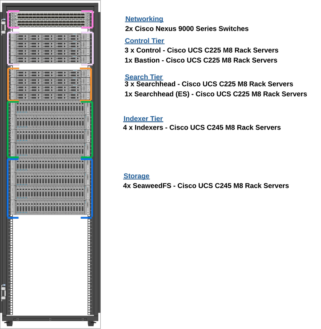
Figure 3 illustrates the Splunk POD rack configuration for two 42U server racks for the Extra-Large tier. Note the Extra-Large tier spans two racks since it cannot physically fit in a single 42U rack. It therefore requires a total of 4 Nexus switches, 2 in each rack, for high availability.
Furthermore, for each server role, it is recommended to split the nodes as evenly as possible between the two racks. For example, there are three Cisco UCS C225 machines intended to be used as search heads. It is recommended to place two Cisco UCS C225’s on the first rack and one C225 on the second rack.
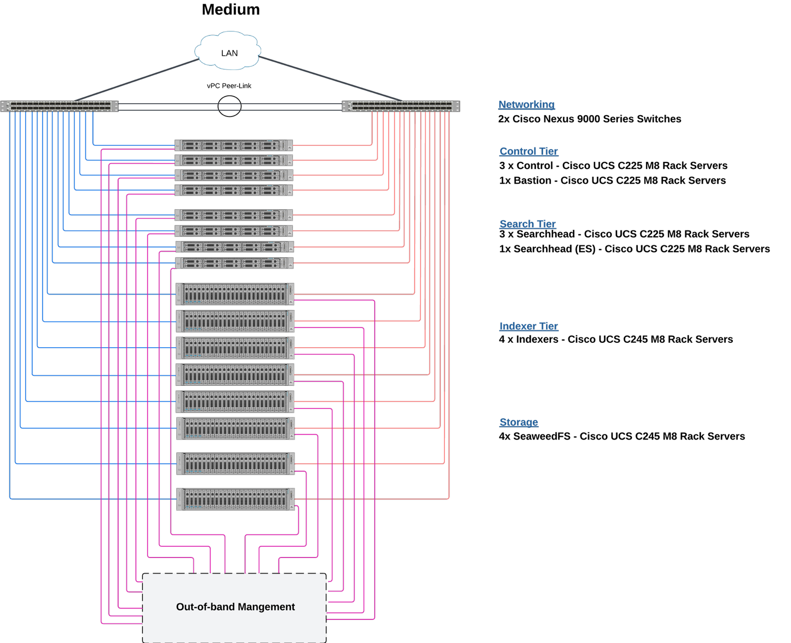
Physical Topology
This reference design shows a typical network configuration for the Medium sizing option. All servers connect to Nexus switches using 100G cables.
Note: This guide does not illustrate the other sizing options.
Host Network
Connect all 100Gbps network cards on each host to the Nexus 9000 switches as shown in Figure 4. Configure the virtual interface cards in physical NIC mode with an OS HA bond to provide network redundancy for the cluster. The following sections include step-by-step instructions for configuring the VICs.
Console Network
All servers in Splunk POD have a 1Gbps console interface port. This allows you to access the virtual console and must be connected to an out-of-band switch that supports 1Gbps connections.
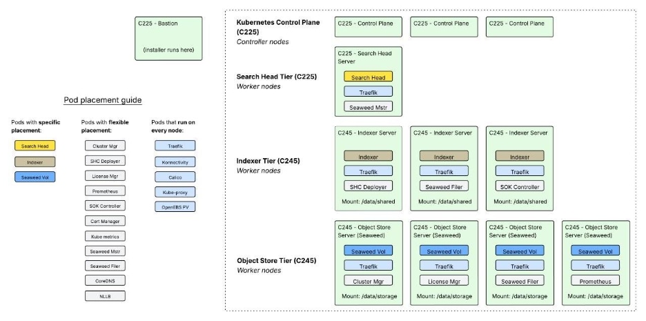
POD Deployment by Host Type
Figure 5 illustrates where the software is deployed in relation to the hardware. Splunk POD deploys each component to different hosts:
● Search Heads are deployed to Cisco UCS C225 machines and utilize the /data/shared mount
● Indexers are deployed to Cisco UCS C245 machines and utilize the /data/shared mount
● SeaweedFS volume pods are deployed to Cisco UCS C245 machines and utilize the /data/storage mount

Splunk POD uses a set of rules to assign pods to specific hosts:
● Strict Separation (Protected Components)
◦ Indexer pods never co-locate with other indexer pods
◦ Search head pods never co-locate with other search head pods
◦ SeaweedFS volume pods never co-locate with other SeaweedFS volume pods
◦ These components are given dedicated hosts when possible
● Flexible Placement (other components)
◦ Cluster Manager, License Manager, Deployer, Monitoring Console
◦ Can co-locate with protected components if CPU/memory resources allow
◦ May vary in placement between cluster deployments
● Fallback Behavior
◦ If insufficient hosts with expected device names/mounts exist, pods will still schedule
◦ Allows for emergency node replacement scenarios
◦ Placement rules are soft constraints, not hard requirements
Storage Diagram Deployment
Figure 6 illustrates the architecture and deployment topology of the storage system in Splunk POD.
Cisco UCS Install and Configure
This chapter contains the following:
● Configure Policies for Cisco Server Profile Templates for Each Server Role
This chapter details the Cisco Intersight deployed Cisco UCS C225 and C245 M8 Rack Servers.
Before deploying Splunk, you must configure the UCS servers appropriately. This section contains the required procedures:
● Procedure 1. Configure Cisco UCS Rack Servers
● Procedure 2. Claim Rack Servers in Cisco Intersight Platform
● Procedure 3. Configure Cisco Intersight Account and System Settings
The compute nodes in Cisco UCS are configured using server profiles defined in Cisco Intersight. These server profiles derive all the server characteristics from various policies and templates.
Procedure 1. Configure Cisco UCS Rack Servers
Step 1. Configure CIMC To Standalone Mode; monitor the server boot process until you reach the Cisco menu and press F8 to enter to Cisco IMC Configuration Utility again.
Step 2. Apply the following configuration:
- NIC mode selected to Dedicated
- IP to IPV4
- CIMC IP with an IP in the same subnet as your computer
- NIC redundancy to none
- No VLAN
- IP Address for the CIMC
- Subnet for the CIMC
- Gateway for the CIMC
- Password for the Admin user. This password will be used to log into the CIMC Console later.
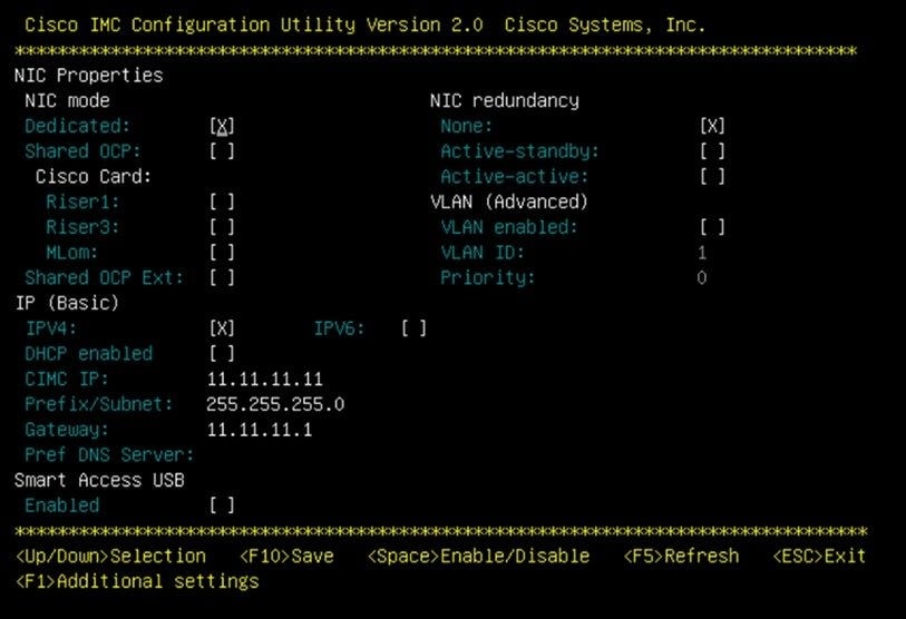
Step 3. Press F10 to save changes and reboot the server.
Step 4. Connect your computer to the physical Management Port on the server and open a web browser.
Step 5. Use the IP you configured https://x.x.x.x
Step 6. Log into the CIMC of your server by accessing https://<CIMC IP Address> and using the username and password. The user is "admin" and the password is the password set in Step 1 during CIMC configuration.
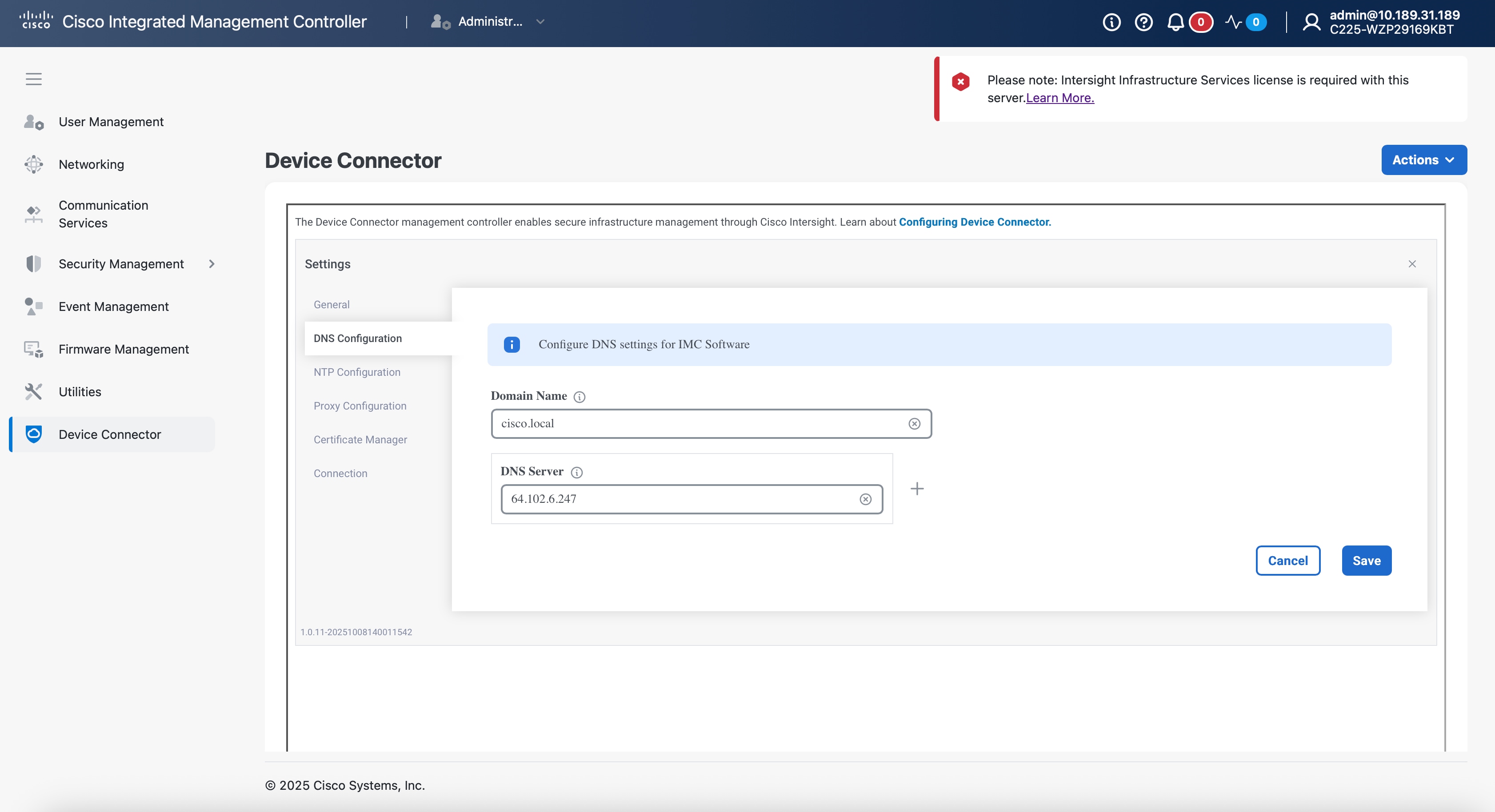
Step 7. Configure the DNS settings by entering your Domain Name and DNS Server.
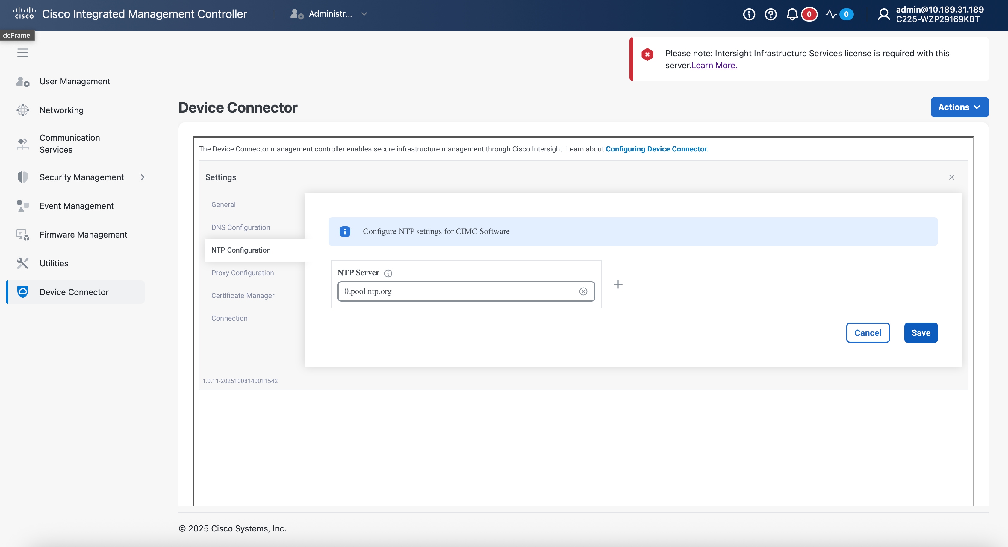
Step 8. Configure the NTP server.
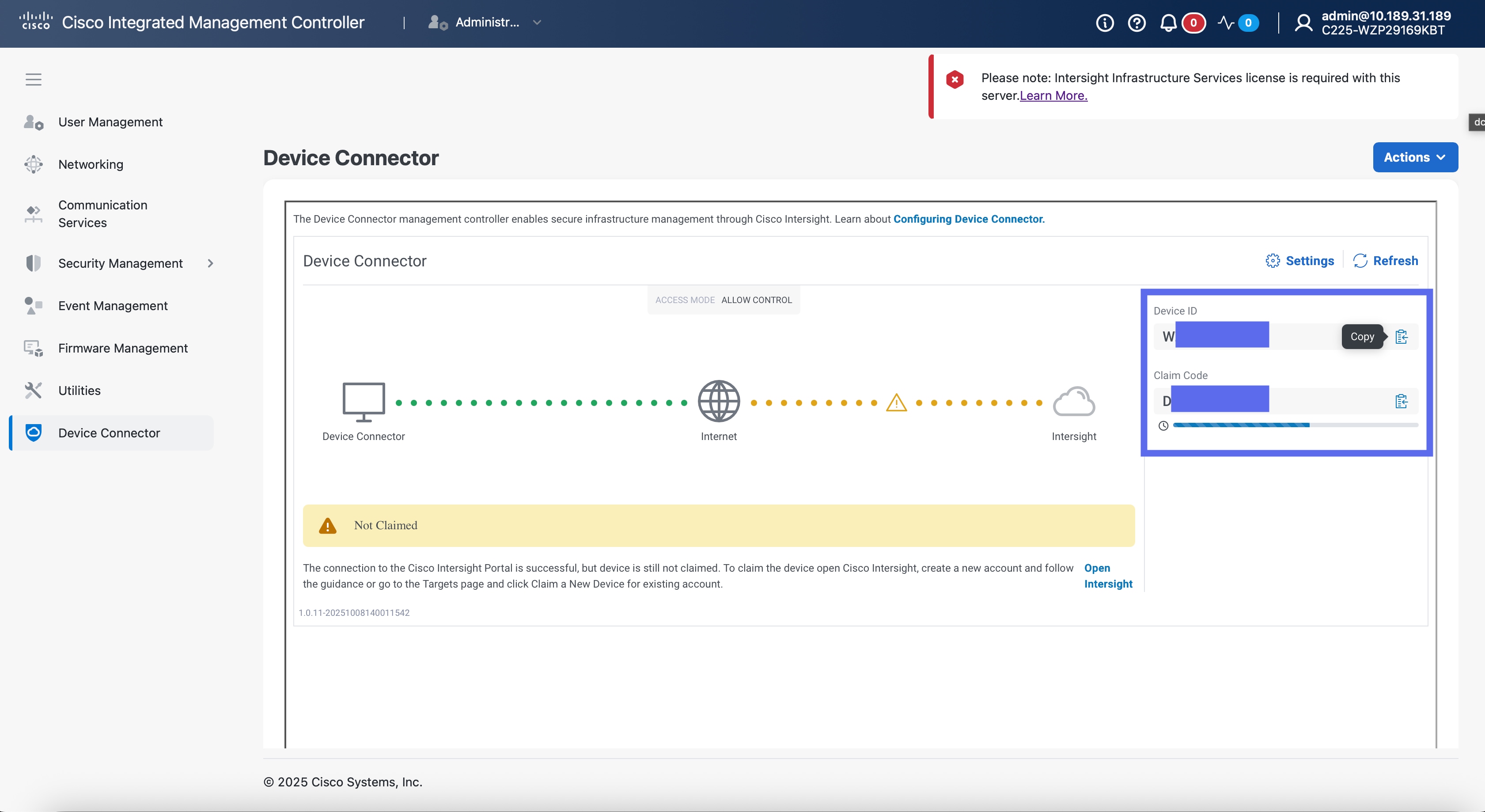
Step 9. Configure any proxy you desire to use by entering its host or IP and the appropriate port.

Step 10. Pause on the screen containing the device and claim codes. You will use these in the following section.
Procedure 2. Claim Rack Servers in Cisco Intersight Platform
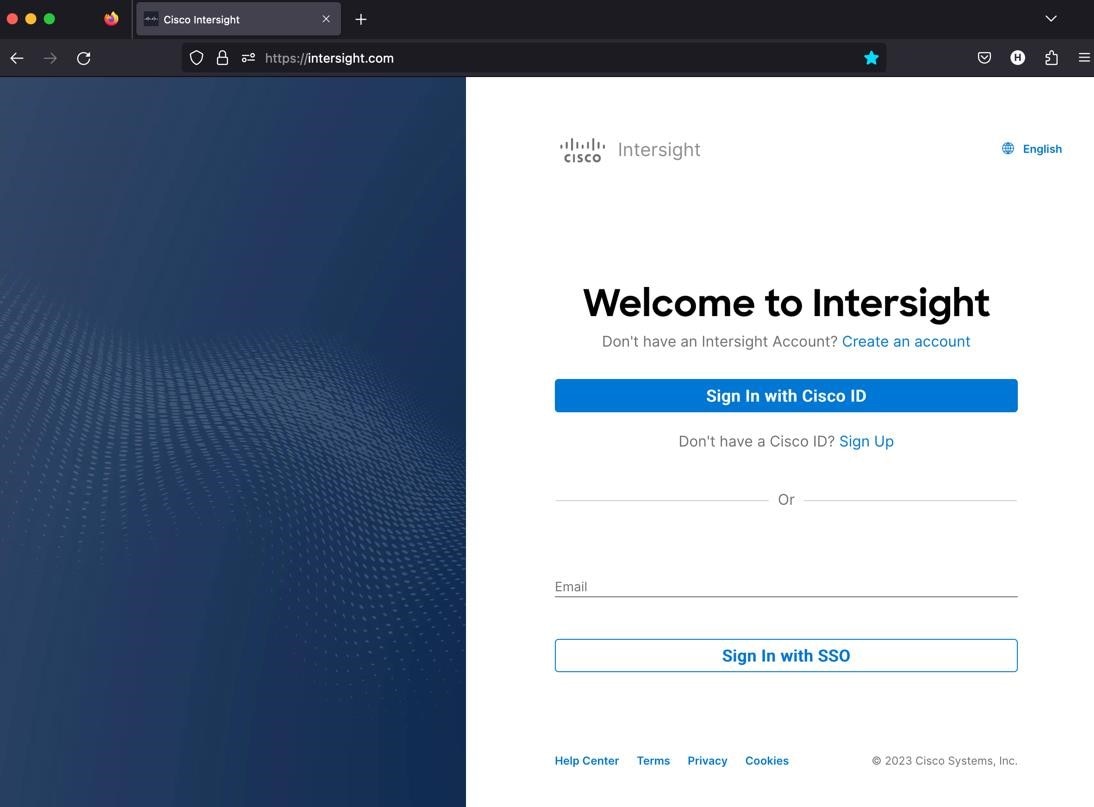
Step 1. Go to https://intersight.com/.
Step 2. Sign in with your Cisco ID or if you don’t have one, click Sign Up and setup your account.
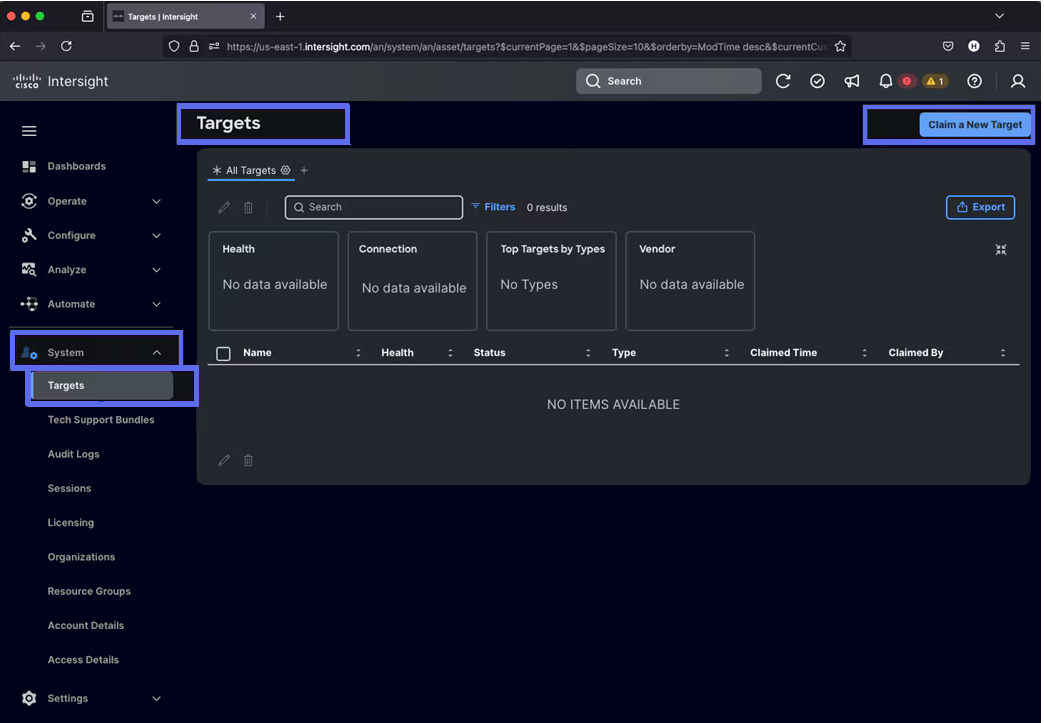
Step 3. After logging into your Cisco Intersight account, go to System > Targets > Claim a New Target.
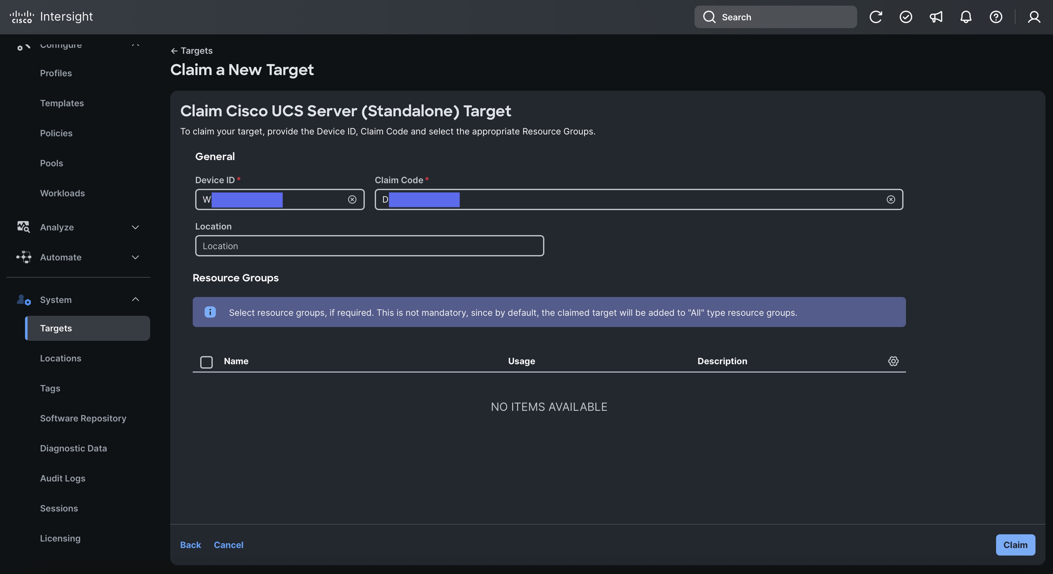
Step 4. For the Select Target Type, select Cisco UCS Server (Standalone) and click Start.
Step 5. Enter the Device ID and Claim Code which was previously captured on the CIMC page. Click Claim to claim this device in Cisco Intersight.

Step 6. Repeat the procedure for the rest of your servers.
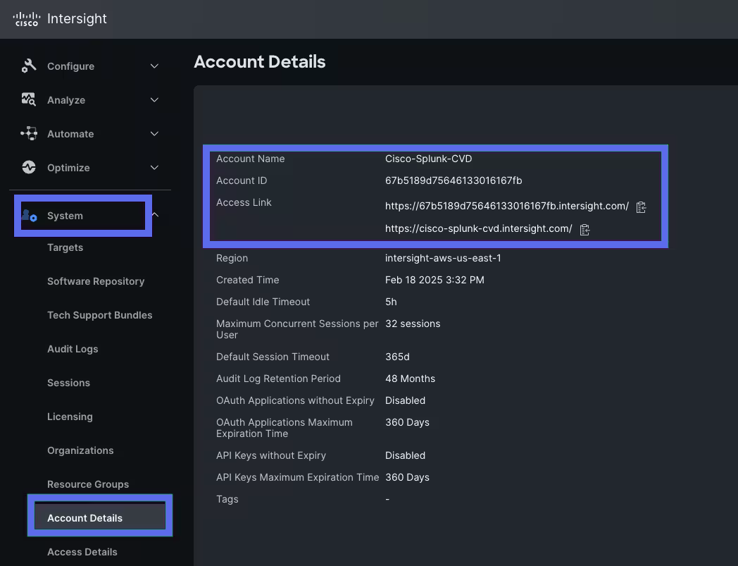
Procedure 3. Configure Cisco Intersight Account and System Settings
Step 1. Go to System > Account Details. For more information, see: https://intersight.com/help/saas/system/settings https://intersight.com/help/saas/system/settings
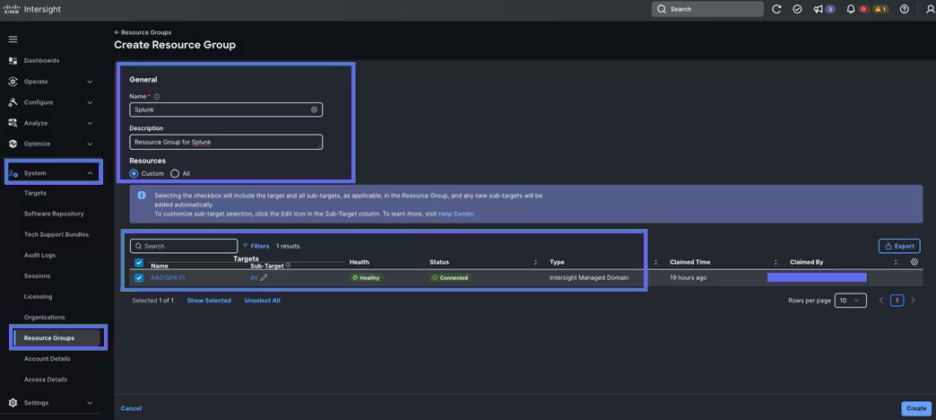
Step 2. In the System tab > Select Resource Group. Create New resource group.
Step 3. Select the Targets to be part of this resource group and click Create.
Note: For this solution, we created new resource group as “Spk-Resource” and selected all the sub-targets as shown below.
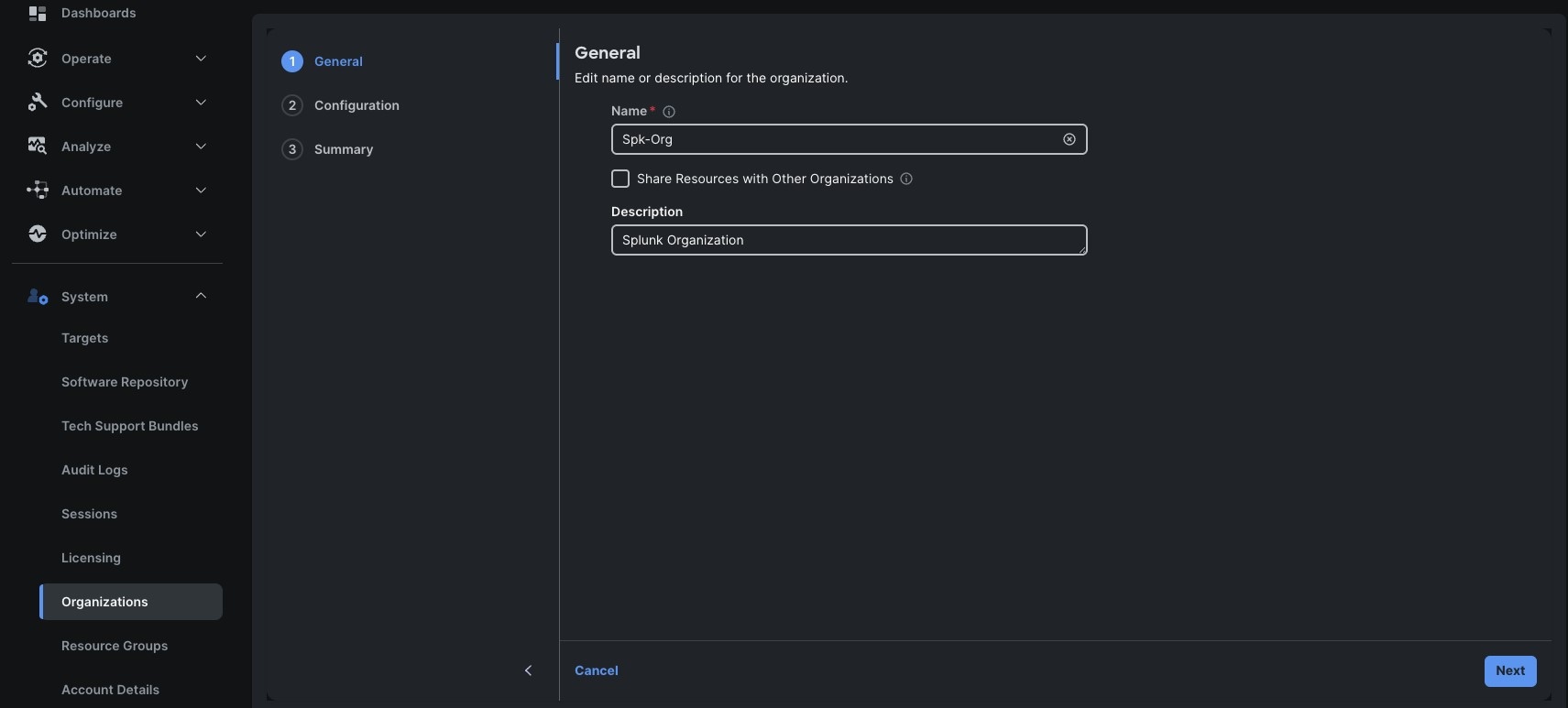
Step 4. Use the Spk-Resource group for this solution. Go to System menu, select Organizations then click Create Organization.
Step 5. Enter the name for the new Organization creation.
Step 6. (Optional) Check the box to share resources with other organizations. Click Next.
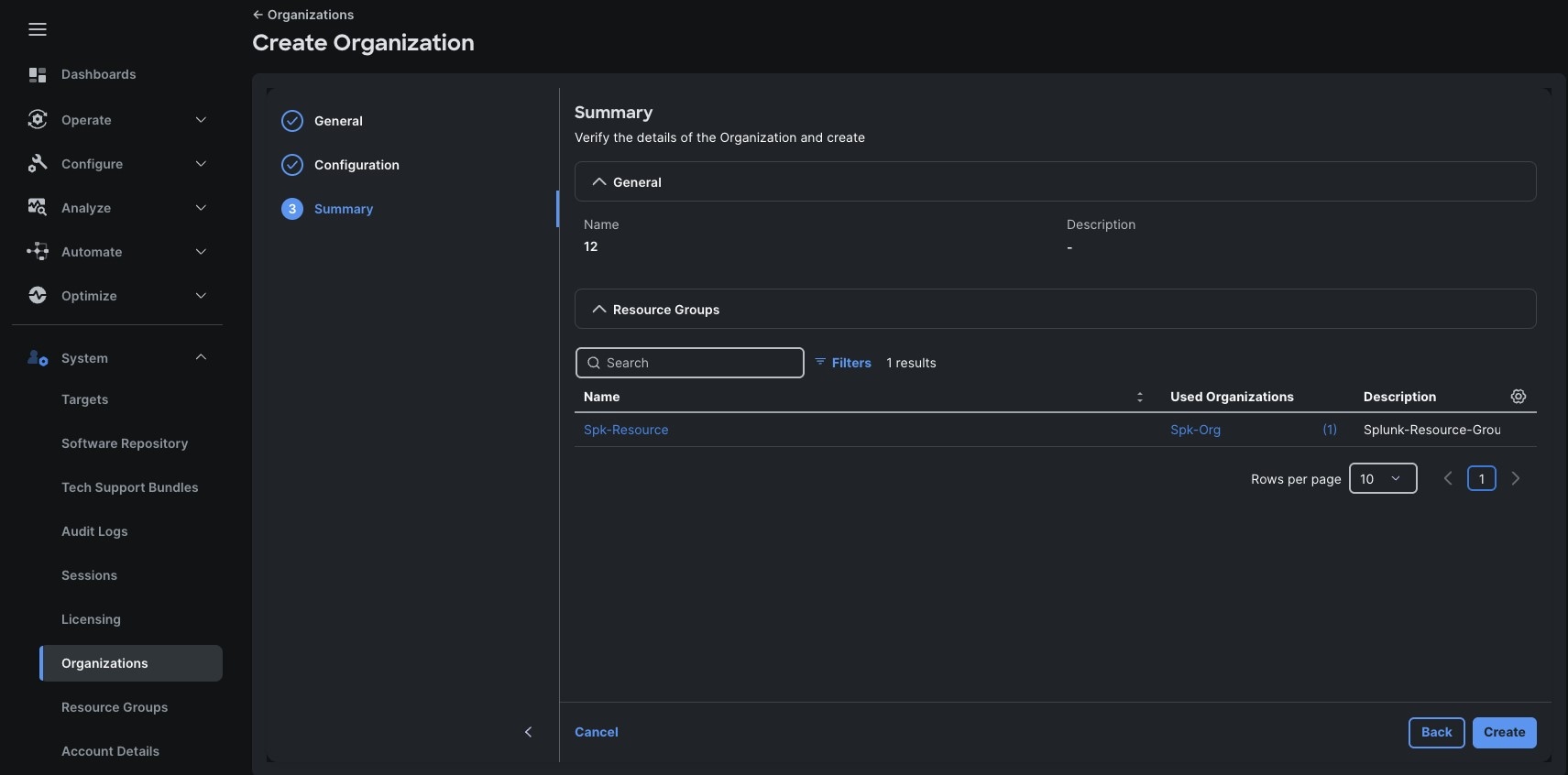
Step 7. In the configuration option, select the “Spk-Resource” configured earlier and click Next.
Step 8. Verify the summary page and then click Create to create organization with resource group for this deployment as shown below:
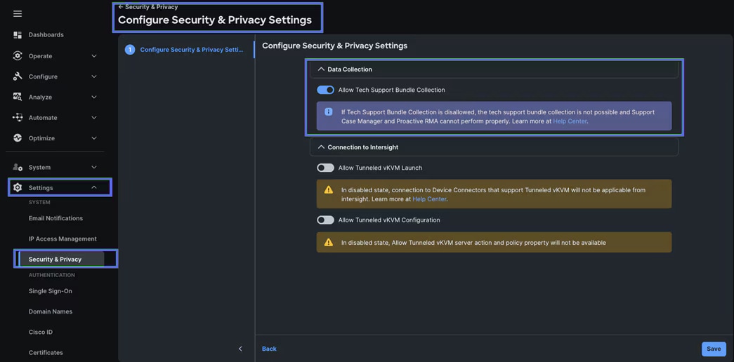
Step 9. To configure Allow Tech Support Bundle Collection, go to Settings > Security & Privacy > and enable the option and then click Save.

Configure Policies for Cisco Server Profile Templates for Each Server Role
A server profile enables resource management by simplifying policy alignment and server configuration. The server profile wizard groups the server policies into the following categories to provide a quick summary view of the policies that are attached to a profile:
● Compute Configuration: BIOS, Boot Order, and Virtual Media policies.
● Management Configuration: Certificate Management, IMC Access, IPMI (Intelligent Platform Management Interface) Over LAN, Local User, Serial Over LAN, SNMP (Simple Network Management Protocol), Syslog and Virtual KVM (Keyboard, Video, and Mouse).
● Storage Configuration: SD Card, Storage.
● Network Configuration: LAN connectivity and SAN connectivity policies.
Some of the characteristics of the server profile template for this solution are as follows:
● BIOS policy is created to specify various server parameters in accordance with AMD CPU’s best practices.
● Boot order policy defines virtual media (KVM mapper DVD) and local boot through M.2 SSD.
● IMC access policy defines the management IP address pool for KVM access.
● LAN connectivity policy is used to create two virtual network interface cards (vNICs) – One vNIC for Server Node Management and Splunk Data Ingestion Network Traffic, second vNIC for Splunk Indexing Server-to-Server Network Traffic Interface.
This section contains the following procedures to configure the various UCS Server Templates. It details:
● Procedure 1. Create UUID Pool
● Procedure 2. Configure BIOS Policy
● Procedure 3. Create Boot Order Policy
● Procedure 4. Create an Adapter Policy
● Procedure 5. Create C245 Indexer Storage Policy
● Procedure 6. Create C245 Volume Server Storage Policy
● Procedure 7. Create C225 Server Storage Policy
● Procedure 8. Create Indexer Server Profile Template
● Procedure 9. Create Volume Server Profile Template
● Procedure 10. Create Controllers Server Profile Template
● Procedure 11. Create Search Head Server Profile Template
● Procedure 12. Create Bastion Server Profile Template
● Procedure 13. Assign and Deploy Server Profiles
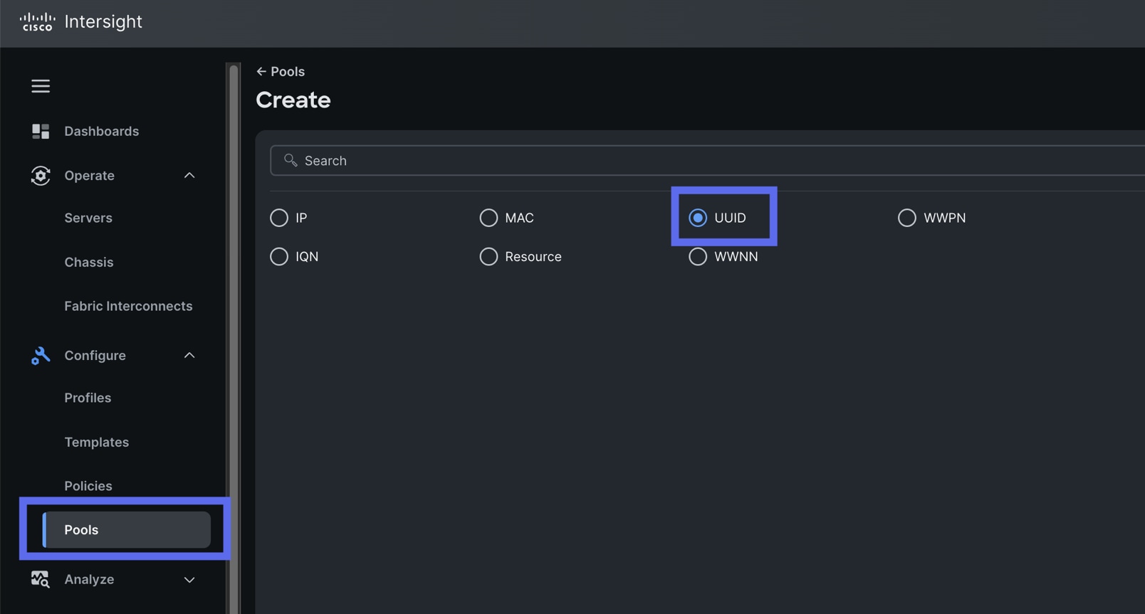
Procedure 1. Configure UUID Pool
Step 1. To create UUID Pool for a Cisco UCS, go to Configure > Pools > and click Create Pool. Select UUID.
Step 2. In the UUID Pool Create section, for the Organization, select “Spk-Org” and for the Policy name “Spk-UUID.” Click Next.
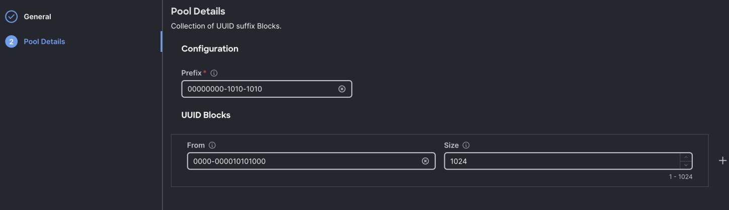
Step 3. Select Prefix, UUID block and size according to your environment and click Create as shown below:
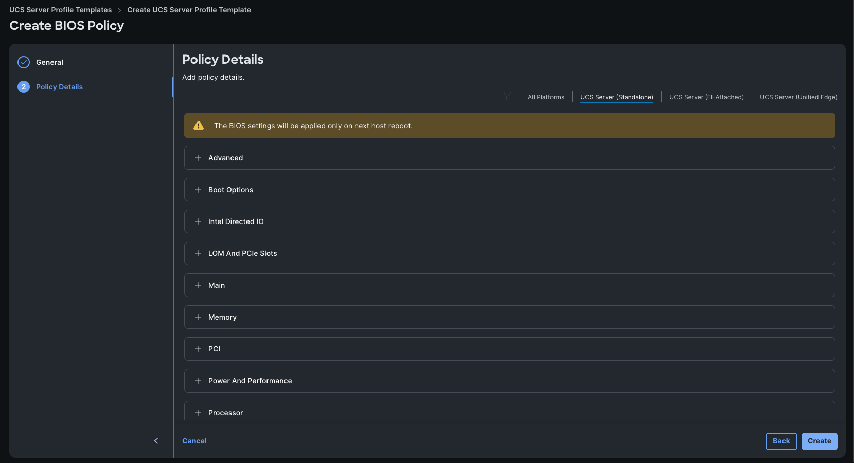
Procedure 2. Configure BIOS Policy
Note: For more information, see Performance Tuning for Cisco UCS M8 Platforms with AMD EPYC 4th Gen and 5th Gen Processors here: https://www.cisco.com/c/en/us/products/collateral/servers-unified-computing/ucs-c-series-rack-servers/ucs-c245-m8-rack-ser-4th-gen-amd-epyc-pro-wp.html
Note: For this specific solution, we created a single BIOS policy (for both single socket Cisco UCS C225 servers and two socket Cisco UCS C245 M8 Server node) and used the setting as listed in Table 11.
Table 11. BIOS recommendations for Splunk Analytical Enterprise Workloads
| BIOS Option |
Default |
Required |
| Processor |
||
| SMT mode |
Enabled |
Enabled |
| SVM mode |
Auto (Enabled) |
Auto |
| DF C-states |
Auto (Enabled) |
Auto |
| ACPI SRAT L3 Cache as NUMA Domain |
Auto (Disabled) |
Auto |
| APBDIS |
Auto (0) |
1 |
| Fixed SOC P-State SP5F 19h |
Auto (P0) |
Auto |
| 4-link xGMI max speed* |
Auto (32Gbps) |
Auto |
| Enhanced CPU performance* |
Disabled |
Disabled |
| Memory |
||
| NUMA nodes per socket |
Auto (NPS1) |
Auto |
| IOMMU |
Auto (Enabled) |
Auto |
| Memory interleaving |
Auto (Enabled) |
Auto |
| Power/Performance |
||
| Core performance boost |
Auto (Enabled) |
Auto |
| Global C-State control |
Auto (Enabled) |
Auto |
| L1 Stream HW Prefetcher |
Auto (Enabled) |
Auto |
| L2 Stream HW Prefetcher |
Auto (Enabled) |
Auto |
| Processor |
||
| Determinism slider |
Auto (Power) |
Auto |
| CPPC |
Auto (Disabled) |
Enabled |
| Global C-State control |
Auto (Enabled) |
Auto |
| L1 Stream HW Prefetcher |
Auto (Enabled) |
Auto |
| Power profile selection F19h |
High-performance mode |
High-performance mode |
Step 1. Go to Configure > Policies > and select Platform type as UCS Server and select on BIOS and click Start.
Step 2. In the BIOS create general menu, for the Organization, select Spk-Org and for the Policy name SpkBIOS-Policy. Click Next.
Step 3. Apply the mentioned parameters from the above table to configure the BIOS for C225 and C245 M8 Server running as Big-Data Analytical workloads.
Step 4. Click Create to create the BIOS policy.
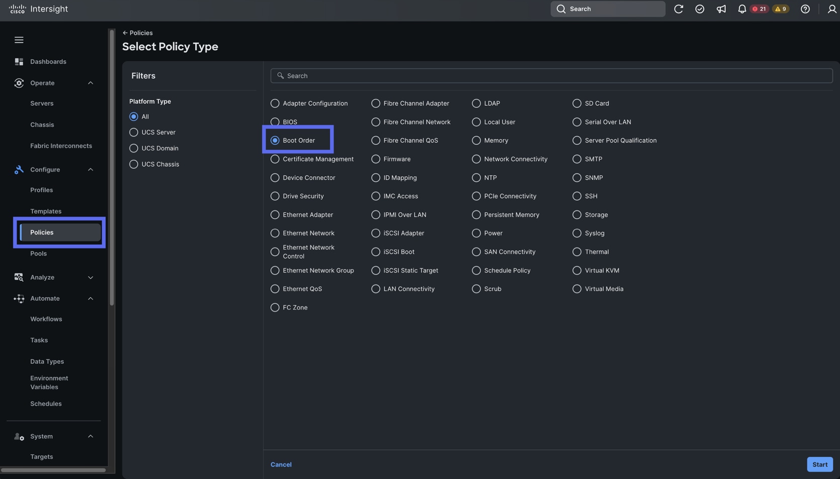
Procedure 3. Create Boot Order Policy
Step 1. To configure Boot Order Policy for a Cisco UCS Server Profile template profile, go to Configure > Polices > and click Create Policy. Select UCS Server and then Boot Order. Click Start.
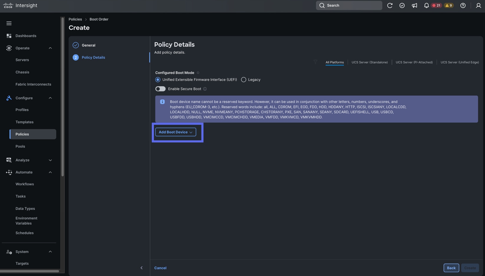
Step 2. Select Unified Extensible Firmware Interface (UEFI) and select UCS Server (Standalone).
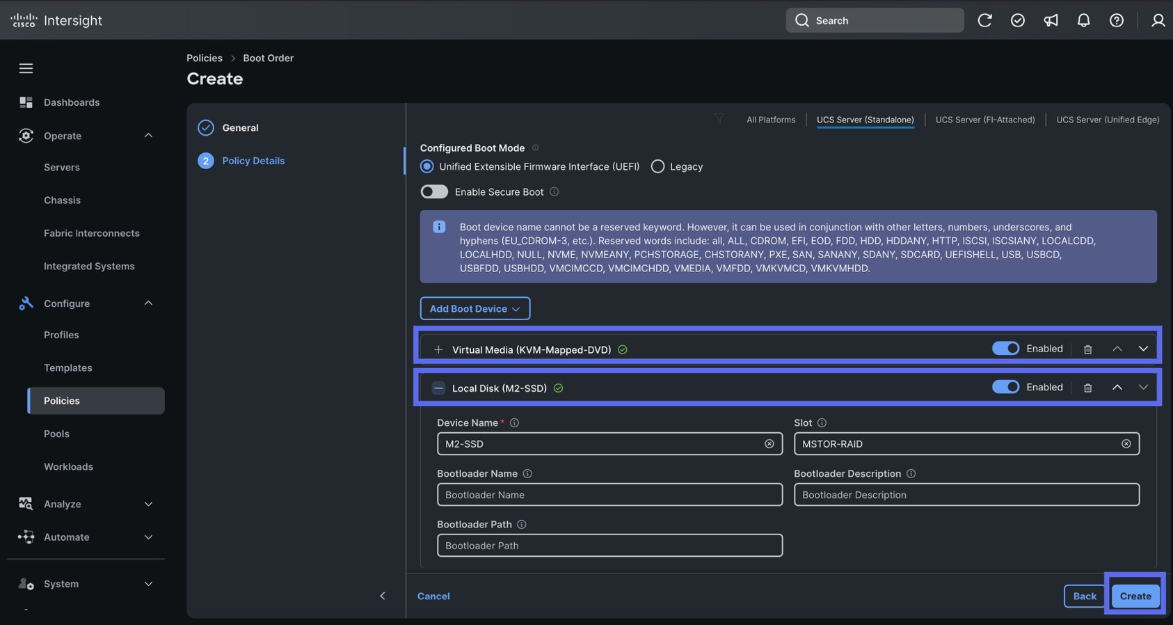
Step 3. Create the first Boot Device by clicking Add Boot Device. For Device Name, enter “KVM-Mapped-DVD” and for Sub-Type, select KVM MAPPED DVD.
Step 4. Create the second Boot Device by clicking Add Boot Device again. For Device Name, enter “M2-SSD” and for Slot, enter “MSTOR-RAID.”
Step 5. Ensure both slots are set to Enabled then click Create.
Procedure 4. Create An Adapter Policy
In this procedure, you will configure the network adapter policy for the servers
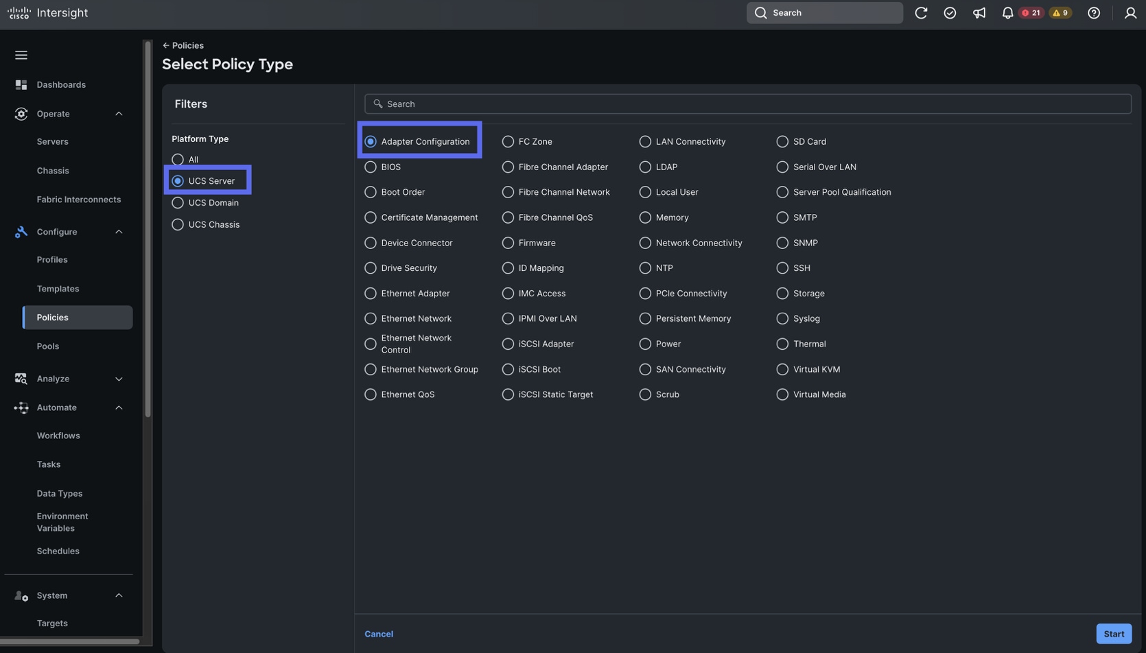
Step 1. Go to Configure > Polices > and click Create Policy. For the Platform Type, select UCS Server, for the Policy select Adapter Configuration. Click Start.
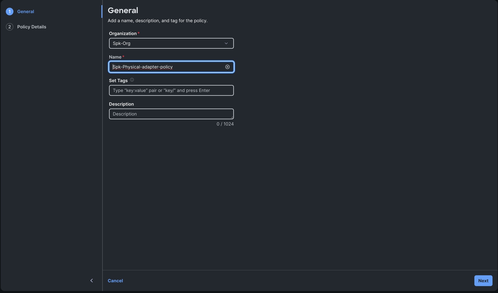
Step 2. Select Spk-Org for Organization and name the policy “Spk-Physical-adapter-policy.” Click Next.
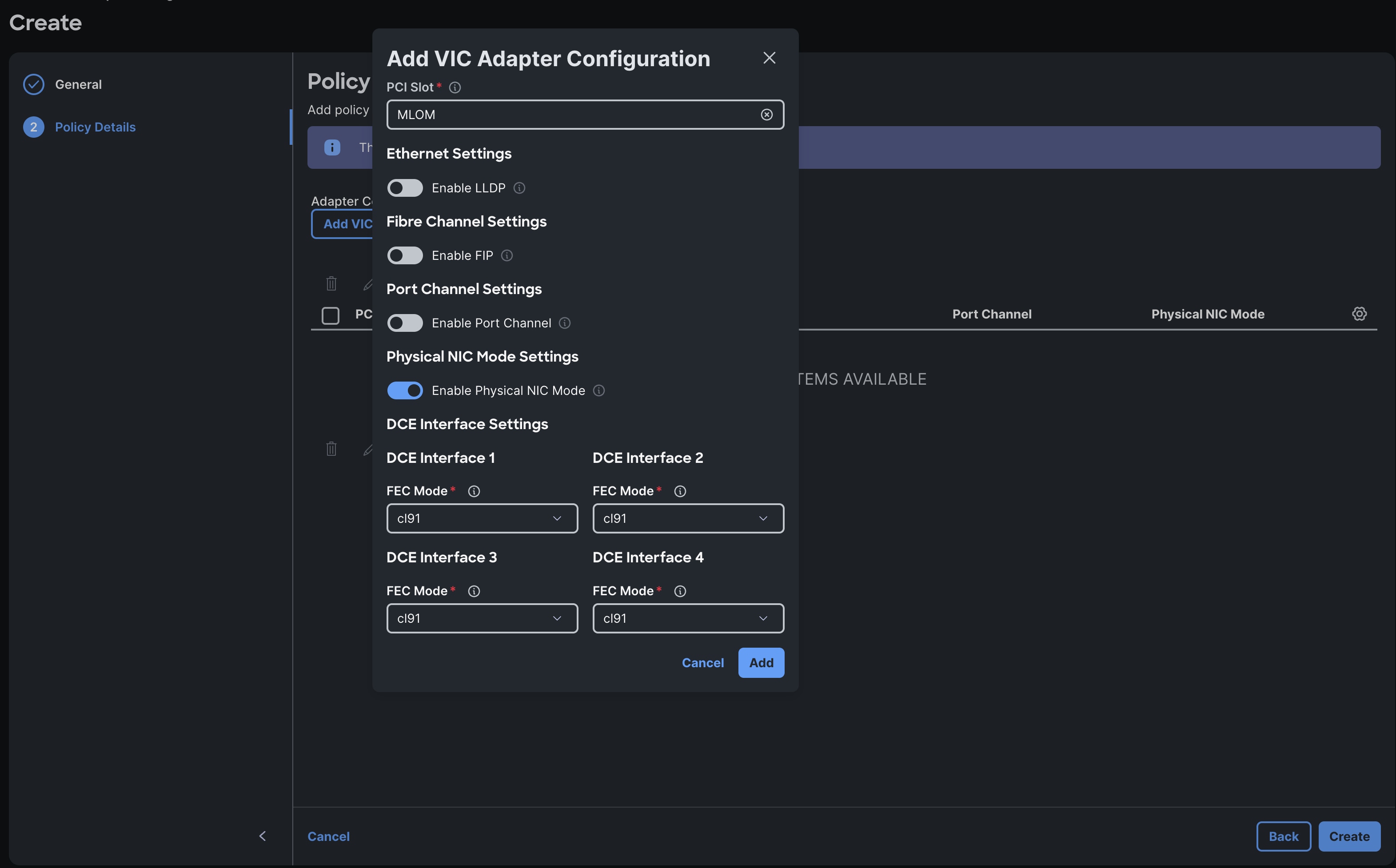
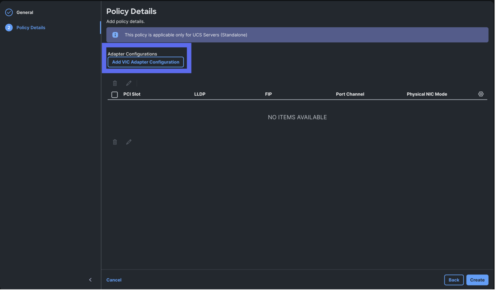
Step 3. Click Add VIC Adapter Configuration.

Step 4. Update the Configuration with the following parameters:
- Set the PCI slot to MLOM
- Disable LLDP
- Disable FIP
- Disable Port Channel
- Enable Physical NIC Mode
- FEC Mode for all interfaces is cl91
Step 5. Click Add.
Step 6. Click Create.
Procedure 5. Create Indexer Server Storage Policies
In this procedure, you will configure the storage policies for the Cisco UCS C245 Indexers servers, Cisco UCS C245 Volume servers, and Cisco UCS C225 servers.
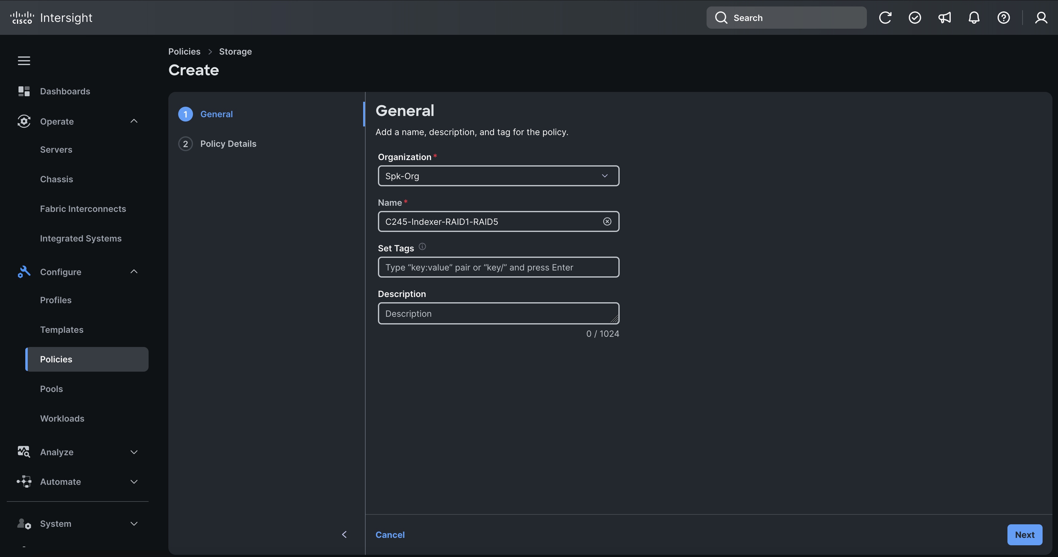
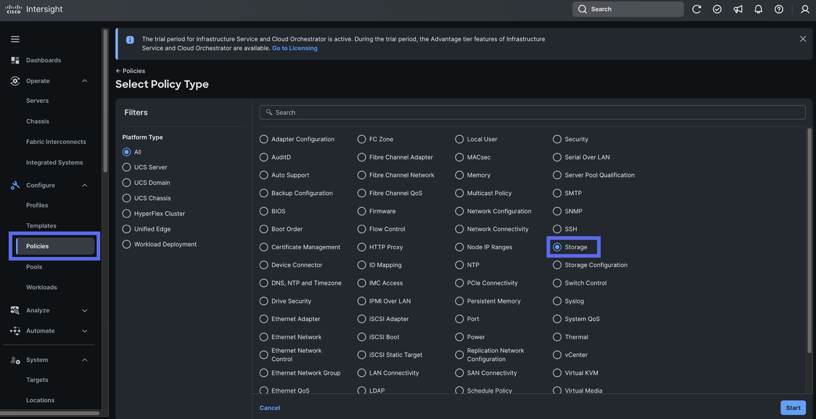
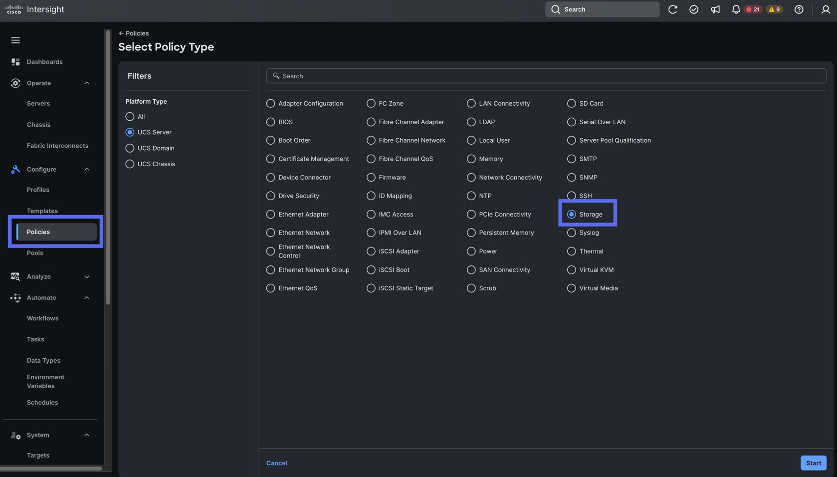
Step 1. Go to Configure > Polices > and click Create Policy. For the platform type select UCS Server and for the Policy select Storage.
Step 2. For the Organization, select Spk-Org, and for the name, enter “C245-Indexer-RAID1-RAID5.” Click Next.

Step 3. In the Policy Details section select UCS Server (Standalone) as the policy.
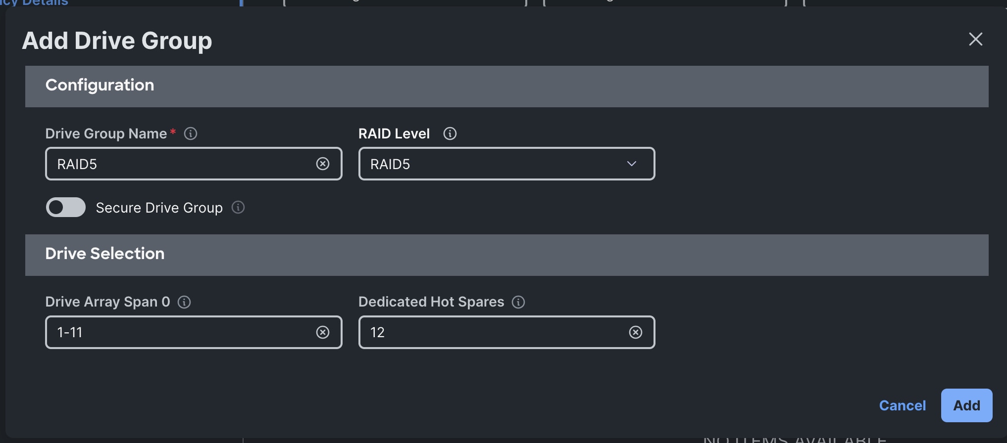
Step 4. On the same page, toggle the option for “MRAID/RAID Controller Configuration” and then click Add Drive Group.
Step 5. In the Add Drive Group modal, enter “RAID5” in the Drive Group Name and select RAID5 as the RAID Level. For the Drive Array Span 0, enter in “1-11” then enter in “12” for the Dedicated Hot Spares option.
Step 6. Click Add Virtual Drive. In the “Add Virtual Drive” modal, enter in the following options:
- Drive Groups: RAID5
- Virtual Drive Name: RAID5
- Expand to Available: Toggled on
- Strip Size: 64KiB
- Access Policy: Default
- Read Policy: No Read Ahead
- Write Policy: Write Through
- Disk Cache: Disabled
Step 7. Click Add.
Step 8. Click Create when the Drive Group and Virtual Drive have been configured.
Procedure 6. Create Volume Server Storage Policies
Configure the Volume Server storage policies for the Volume servers with this procedure.
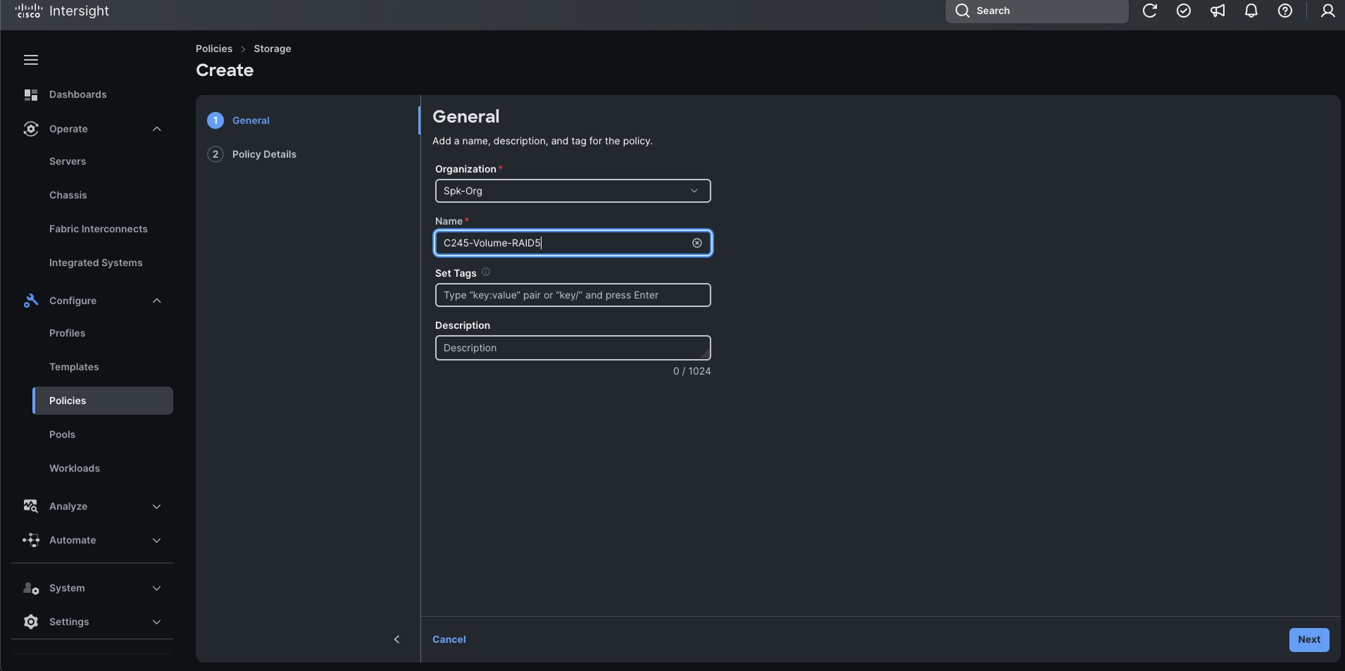
Step 1. Go to Configure > Polices > and click Create Policy. For the platform type, select UCS Server and for the Policy select Storage.
Step 2. In the Create section, for the Organization, select Spk-Org, for the policy name enter “C245-Volume-RAID5.” Click Next.
Step 3. In the Policy Details section select UCS Server (Standalone) as the policy.
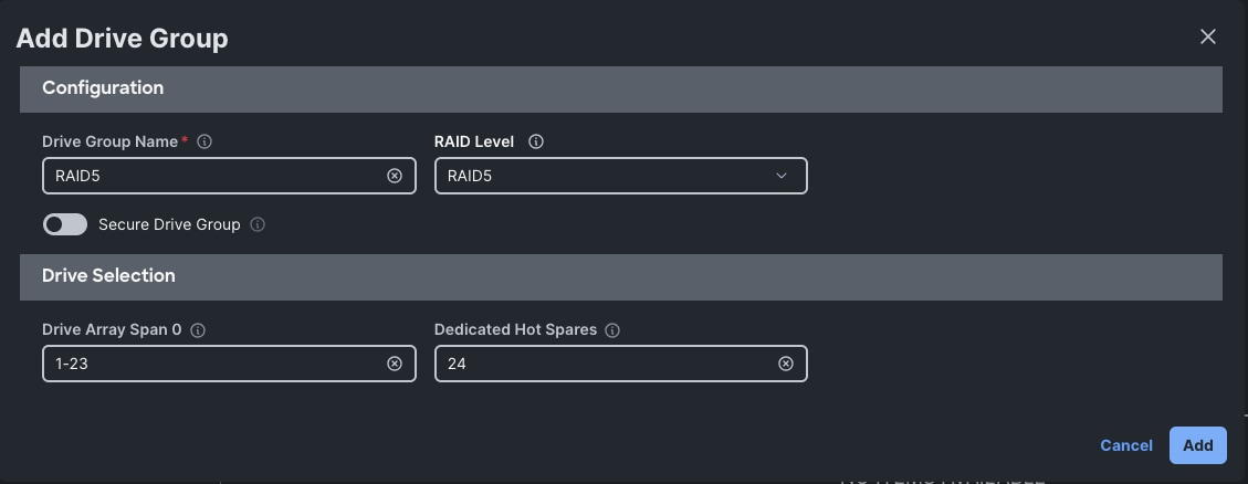
Step 4. On the same page, toggle the option for “MRAID/RAID Controller Configuration” and then click Add Drive Group.
Step 5. In the Add Drive Group modal, enter “RAID5” in the Drive Group Name and select “RAID5” as the RAID Level. For the Drive Array Span 0, enter in “1-23” then enter in “24” for the Dedicated Hot Spares option.
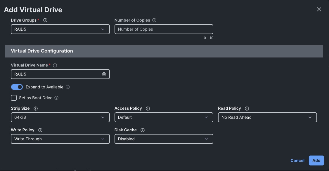
Step 6. Click Add Virtual Drive. In the “Add Virtual Drive” modal, enter in the following options:
- Drive Groups: RAID5
- Virtual Drive Name: RAID5
- Expand to Available: Toggled on
- Strip Size: 64KiB
- Access Policy: Default
- Read Policy: No Read Ahead
- Write Policy: Write Through
- Disk Cache: Disabled
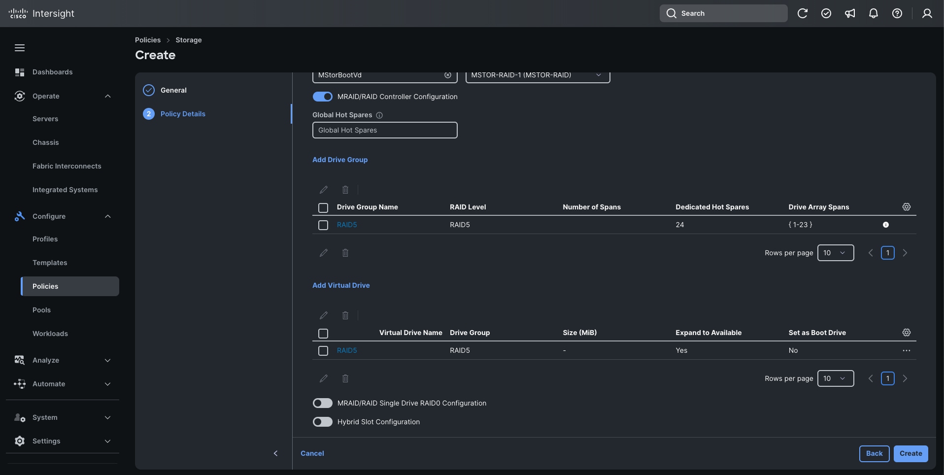
Step 7. Click Add.
Step 8. Click Create when both the Drive Group and Virtual Drive have been configured.
Procedure 7. Create C225 Storage Policies
Create another storage policy for the Cisco UCS C225 servers. All Cisco UCS C225 machines share the same storage policy.
Step 1. Go to Configure > Polices > and click Create Policy. For the platform type select UCS Server and for the Policy select Storage.
Step 2. In the Create section, for the Organization, select Spk-Org for the policy name enter “C225-Storage-RAID1.” Click Next.
Step 3. In the Policy Details section select UCS Server (Standalone) as the policy.
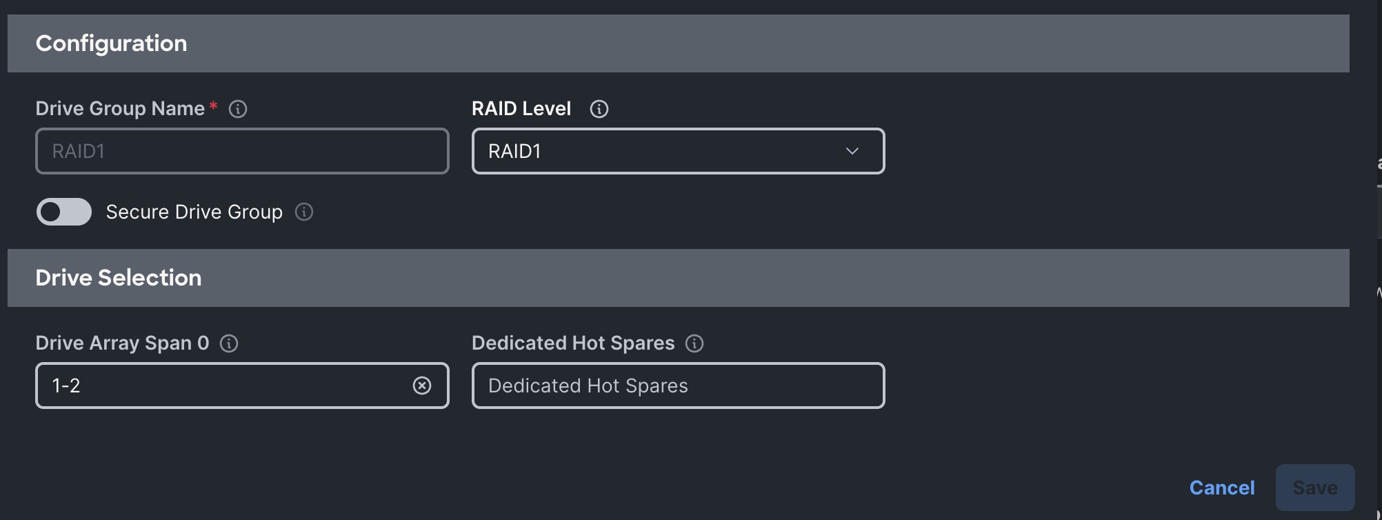
Step 4. On the same page, toggle the option for “MRAID/RAID Controller Configuration” and then click Add Drive Group.
Step 5. In the Add Drive Group modal, enter “RAID1” in the Drive Group Name and select RAID1 as the RAID Level. For the Drive Array Span 0, enter in “1-2.”
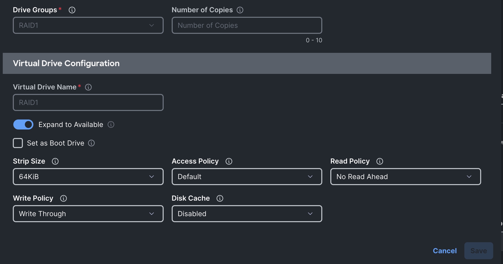
Step 6. Click Add Virtual Drive. In the “Add Virtual Drive” modal, enter in the following options:
- Drive Groups: RAID1
- Virtual Drive Name: RAID1
- Expand to Available: Toggled on
- Strip Size: 64KiB
- Access Policy: Default
- Read Policy: No Read Ahead
- Write Policy: Write Through
- Disk Cache: Disabled
Step 7. Click Add.
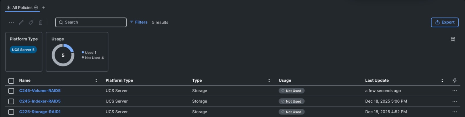
Step 8. Click Create when both the Drive Group and Virtual Drive have been configured. You should have the following policies:

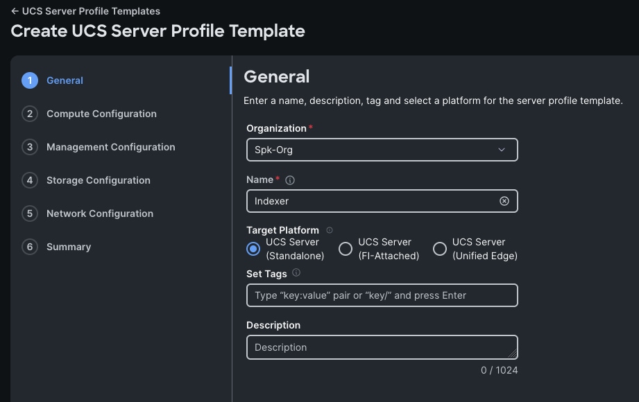
Procedure 8. Create Server Profile Templates
Create server profile templates for the Indexer, Volume, Bastion, Controller, and Search Head servers. You do this by creating the indexer template and then cloning the rest.
Step 1. Go to Configure > Templates > UCS Server Profile Templates and click Create Server Profile Template.
Step 2. For the Organization, select Spk-Org, enter in “Indexer” for the name, and select UCS Server (Standalone) for the Target Platform. Click Next.
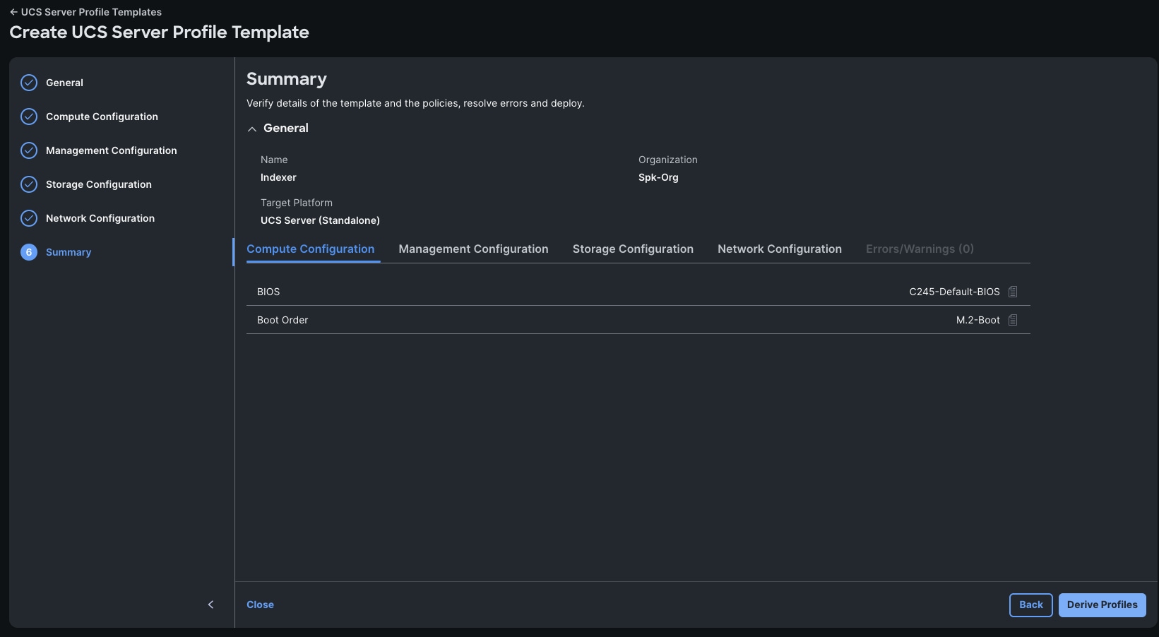
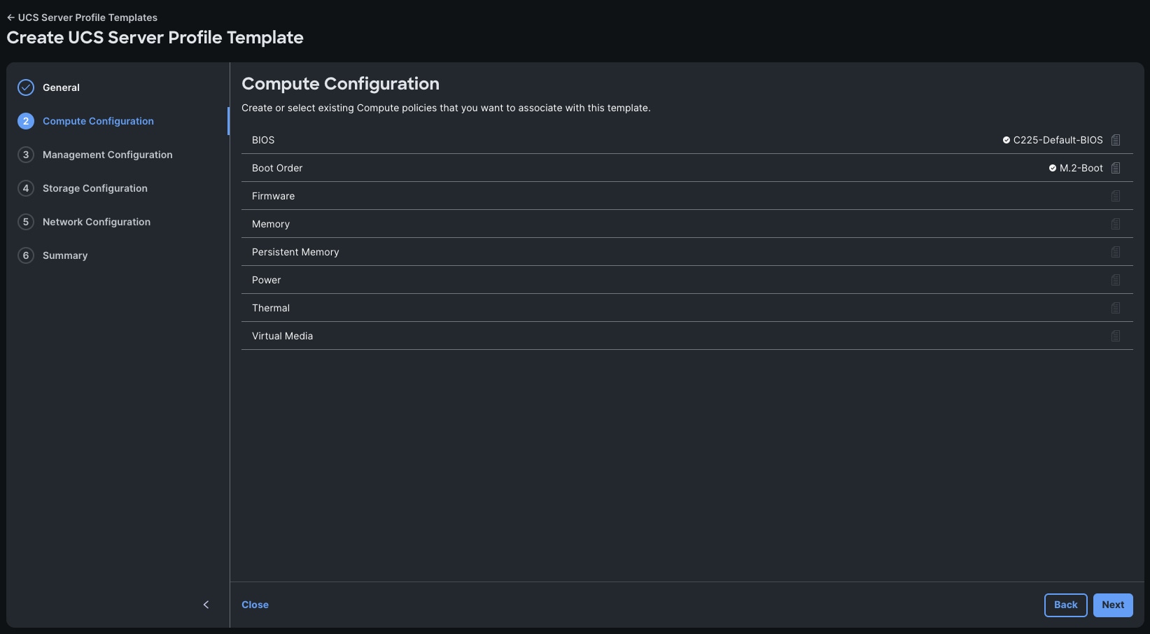
Step 3. In the Compute Configuration step, select the C245-Default-BIOS policy, and select M.2-Boot for the Boot Order which was created in prior steps. Click Next.
Step 4. Click Next in the Management Configuration screen.
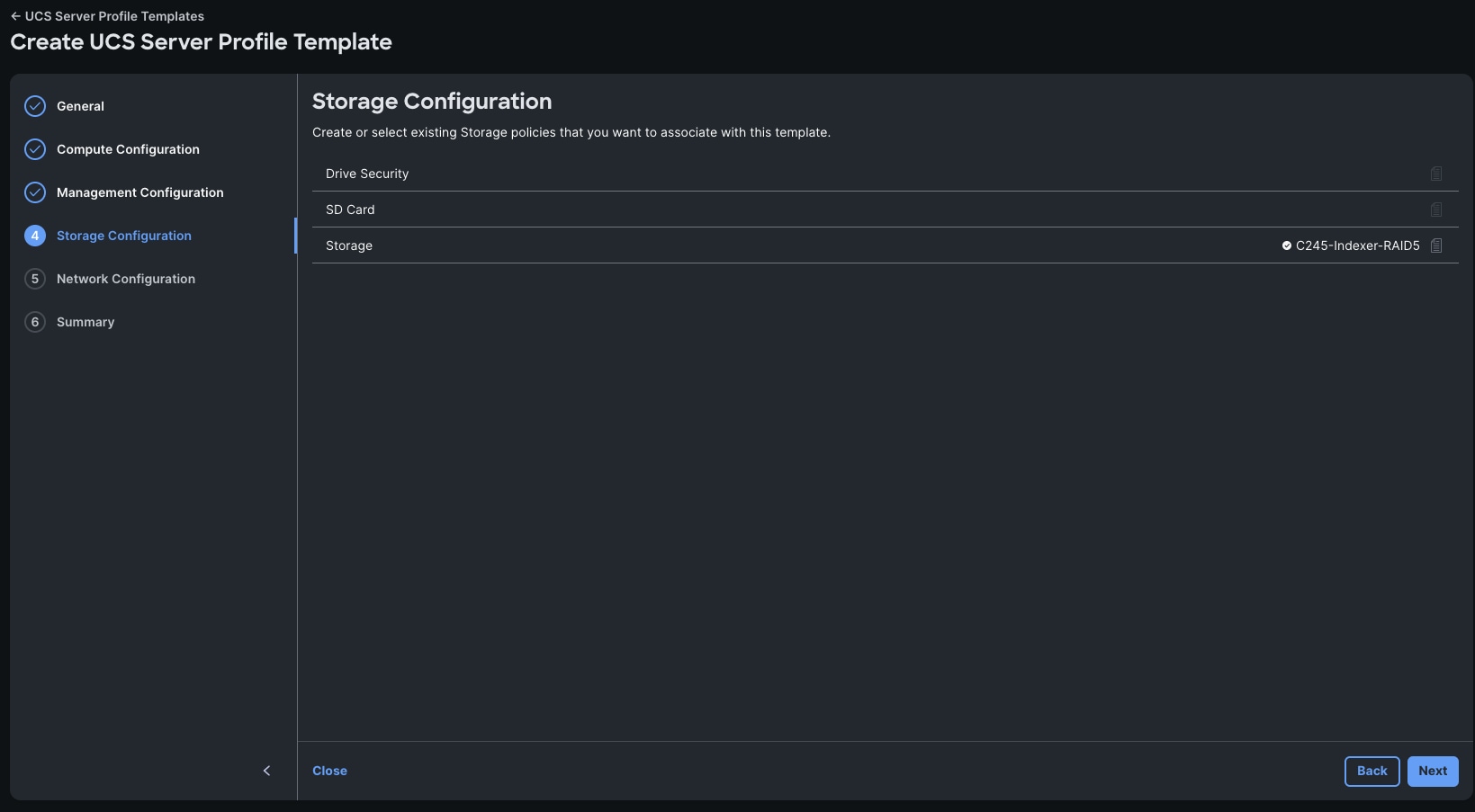
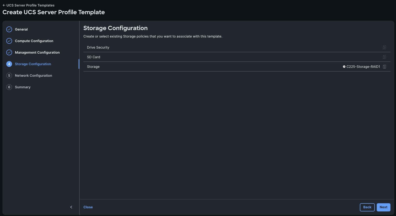
Step 5. From Storage Configuration, select the C245-Indexer-RAID5 storage policy.
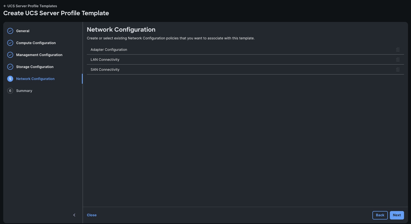
Step 6. Click Next in the Network Configuration screen.

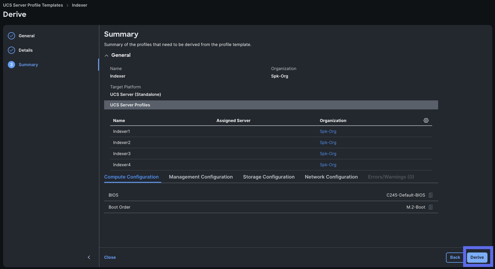
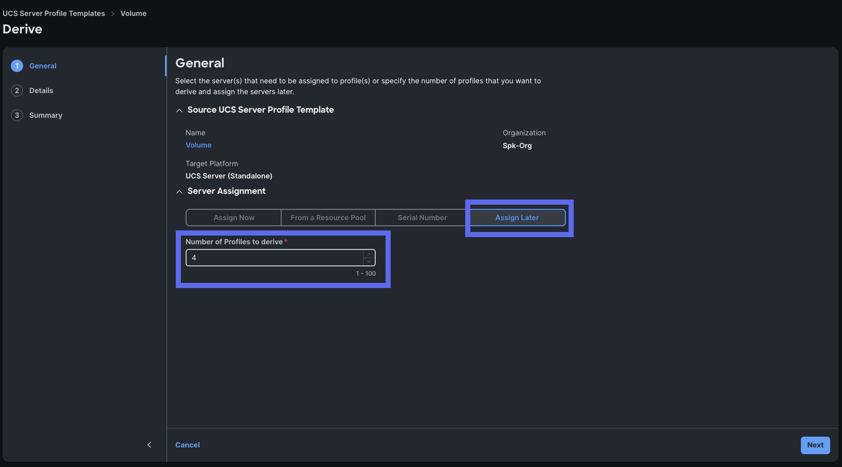
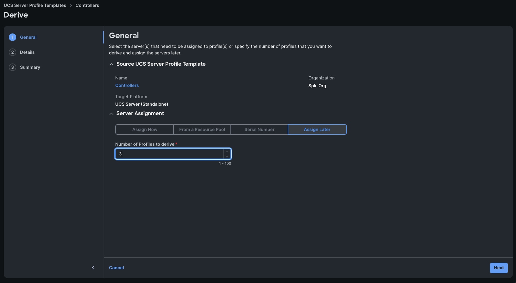
Step 7. Click Derive Profiles in the Summary screen.
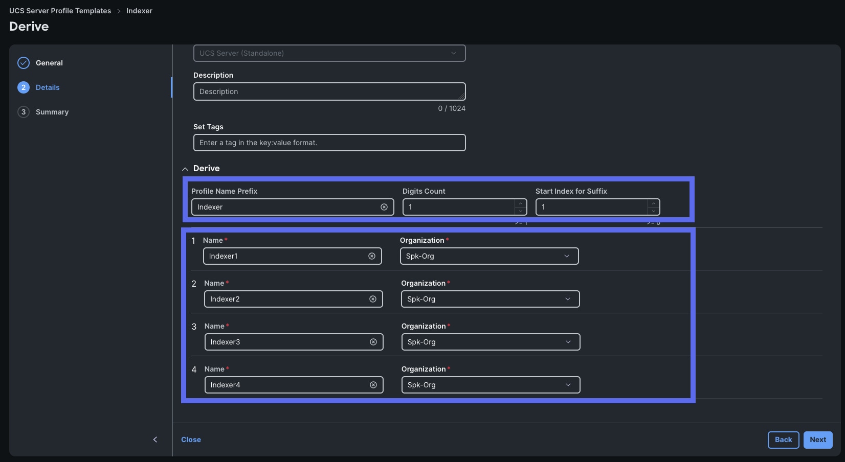
Step 8. In the following screen, enter the number of profiles to derive. This corresponds to the number of Indexers in your profile.
Note: As a reminder, the Small profile has 3 Indexers, the Medium profile has 4 indexers, the Large has 7, and the Extra-Large has 17. Since we are demonstrating the Medium profile, enter 4 indexers and choose Assign Later.
Step 9. Click Next.
Step 10. In the Details screen, expand the Derive option at the bottom, enter in “Indexer” as the Profile Name Prefix, enter “1” for Digits Count, and “1” for Start Index for Suffix.
Step 11. Click Next.
Step 12. Click Derive in the Summary screen.
Procedure 9. Create a Volume Server Profile Template
Create the Volume Server Template by cloning the Indexer template.
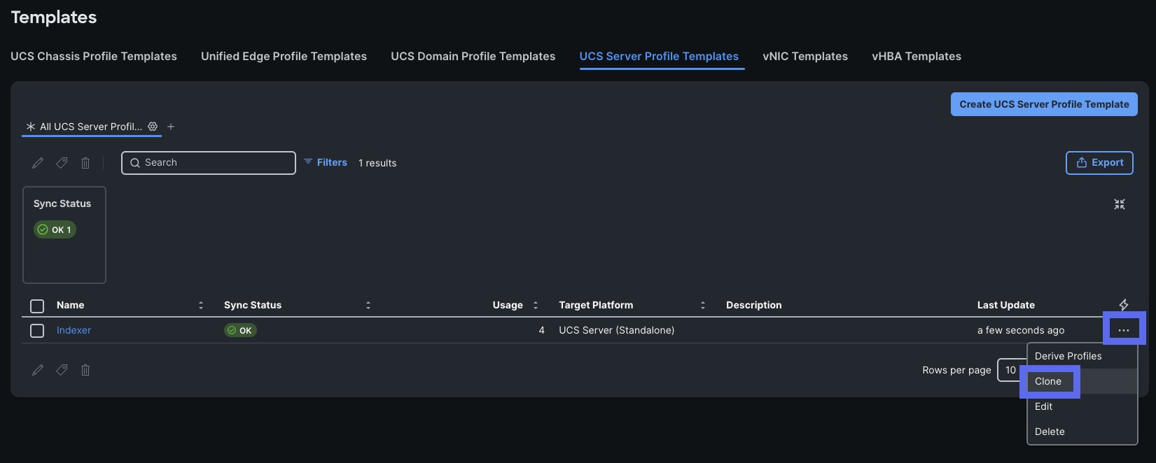
Step 1. Go to Configure > Templates > UCS Server Profile Templates. Locate the Indexer template we just created and click the 3 dots on the right-hand side. Click Clone.
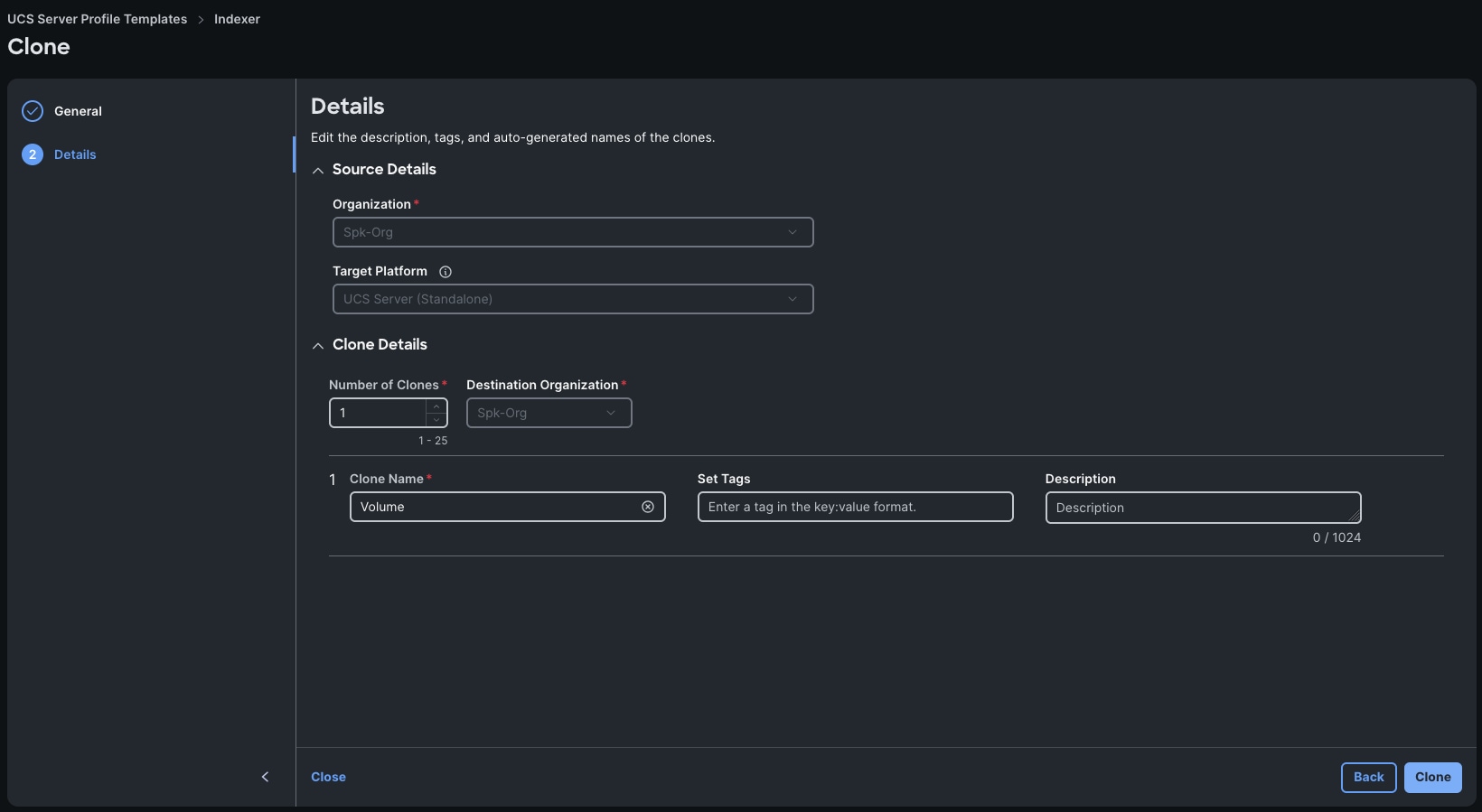
Step 2. In the General screen click Next.
Step 3. In the Details page, change the Clone Name to “Volume.”
Step 4. Click Clone.
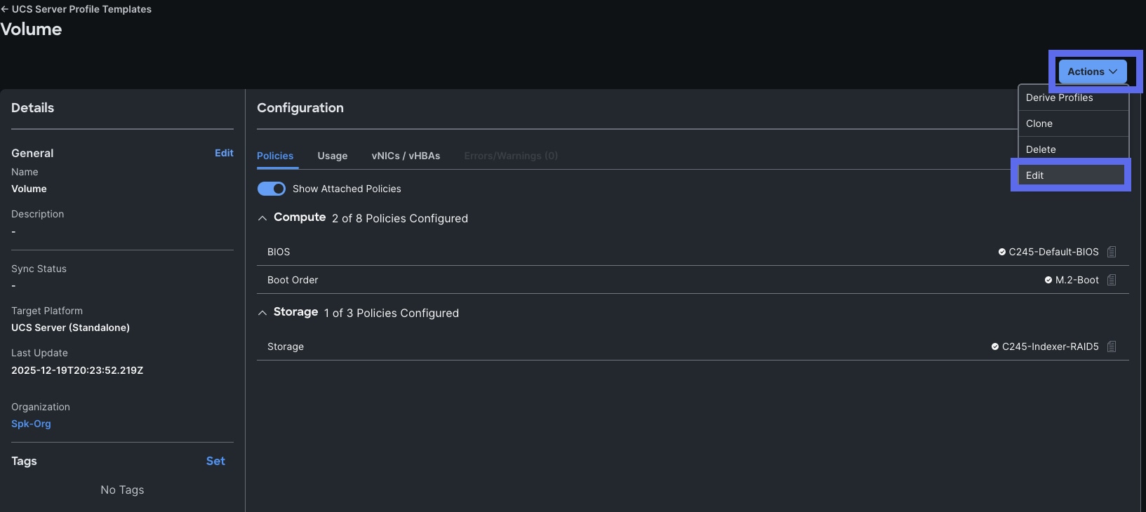
Step 5. When cloned, click Actions on the top-right and select Edit to configure the cloned the Template.
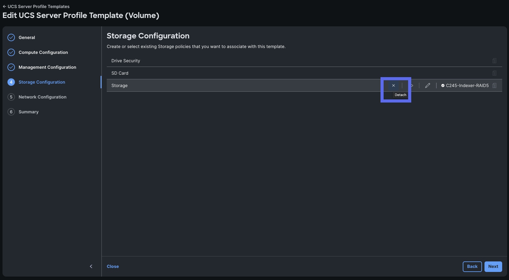
Step 6. Click Next to proceed with the cloned settings until you get to Storage Configuration. Click the X icon to Detach the Storage policy.
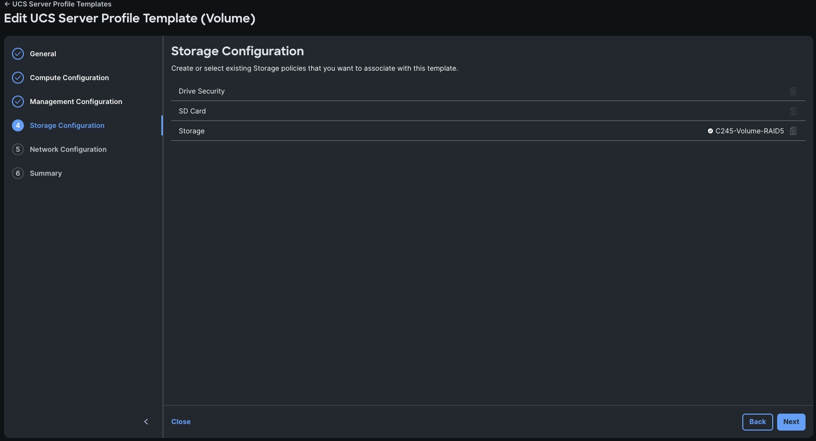
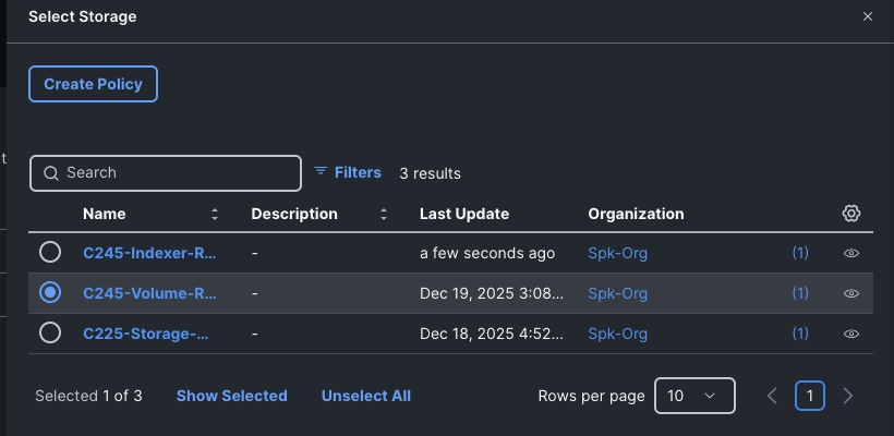
Step 7. Now that the previous policy is detached, attach the C245-Volume-RAID5 policy. When selected, click Next in Storage Configuration to proceed.
Step 8. Click Next on the following screens since you do not need to make any additional changes. When you reach the Summary section, click Derive Profiles.
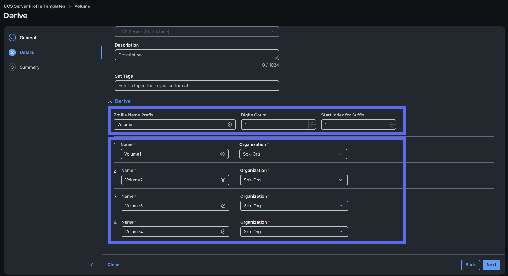
Step 9. Change the number of profiles to derive according to the profile you are using. We will change the Number of Profiles to Derive to 4 for this guide since we are configuring the Medium Profile.
Step 10. In the Details screen, expand the Derive option at the bottom, enter in “Volume” as the Profile Name Prefix, enter “1” for Digits Count, and “1” for Start Index for Suffix.
Step 11. Click Next.
Step 12. Click Derive in the Summary screen.
Procedure 10. Create a Controllers Server Profile Template
Now you will create the Controller Template by cloning the Controller template.
Step 1. Go to > Configure > Templates > UCS Server Profile Templates. Locate the Volume template, click the ellipses, and click Clone.
Step 2. In the General screen click Next.
Step 3. In the Details page, change the Clone Name to “Controller.” Click Clone.
Step 4. When cloned, click Actions on the top-right and select Edit to configure the cloned the Template.
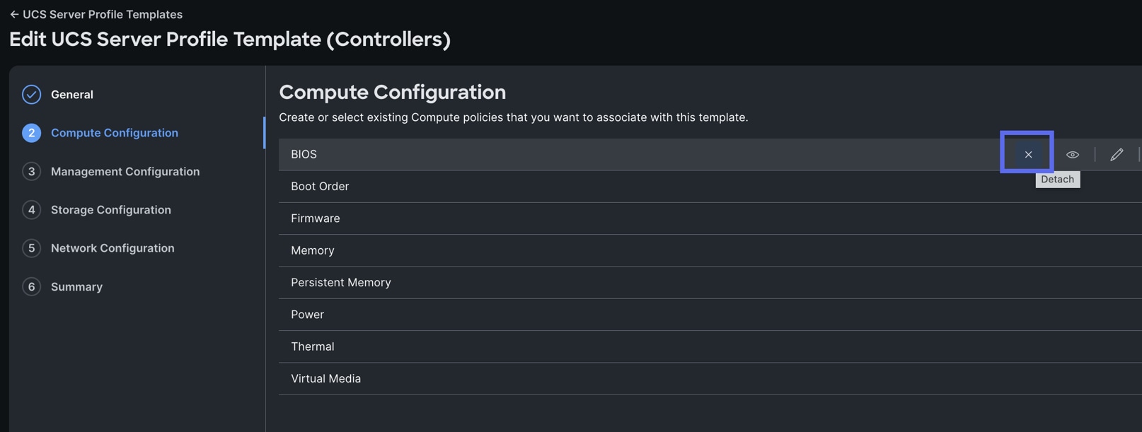
Step 5. Click Next to proceed past the General screen to the Compute Configuration page. Click the X icon to detach the cloned BIOS policy.
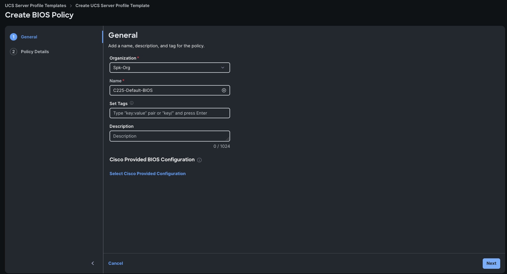
Step 6. When detached, you will create a new Boot Policy for the C225 machines. Click Select the BIOS and then click Create Policy.
Step 7. Enter “C225-Default-BIOS” for the Name and click Next.
Step 8. Click Next.
Note: This creates a default, BIOS Policy. You may configure it according to your needs.
Step 9. When you configured the BIOS Policy, click Next in the Compute Configuration.
Step 10. Proceed through the Management Configuration screen by clicking Next. When you get to the Storage Configuration screen, modify the storage policy to use the “C225-Storage-Policy.”
Step 11. Click Next.
Step 12. Proceed through the Network Configuration screen by clicking Next. When you get to the Summary screen, click Derive Profiles. Enter 3 for the Number of Profiles to derive, choose Assign Later, and click Next.
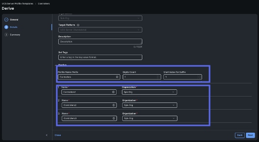
Step 13. In Details, enter “Controller” as the Profile Name Prefix, set Digits Count to 1 and Start Index to 1, then click Next and Derive on the Summary screen.

Procedure 11. Create the Search Head Server Profile Template
Now you will create the Search Head Server Template by cloning the Controller template.
Step 1. Go to Configure > Templates > UCS Server Profile Templates. Locate the Controller template, click the 3 dots on the right, and click Clone.
Step 2. In the General screen click Next.
Step 3. In the Details page, change the Clone Name to “Search Head.” Then click Clone.
Step 4. When cloned, click Actions on the top-right and select Edit to configure the cloned the Template.
Step 5. Click Next to proceed until the Summary Screen. Click Derive.
Step 6. In the Details screen, expand the Derive option at the bottom, enter in “SearchHead” as the Profile Name Prefix, enter “1” for Digits Count, and “1” for Start Index for Suffix.
Step 7. Click Next.
Procedure 12. Assign and Deploy Server Profiles
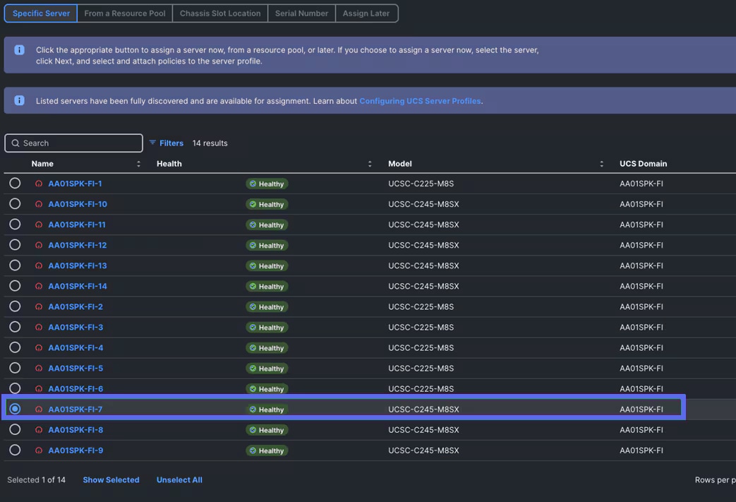
Step 1. Go to > Configure > UCS Server Profiles > then select the server profile “Indexer1” and choose Assign Server from the drop-down list.
Step 2. From the Assign Server to UCS server Profile, select the specific Server where you want to apply this server profile and click Assign.
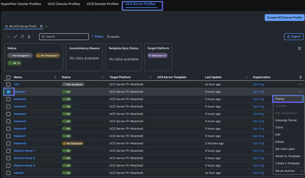
Step 3. After you assign the server profile to the appropriate server, go to Configure > Profiles > UCS Server Profile > select the same server and click Deploy to configure server as shown below:
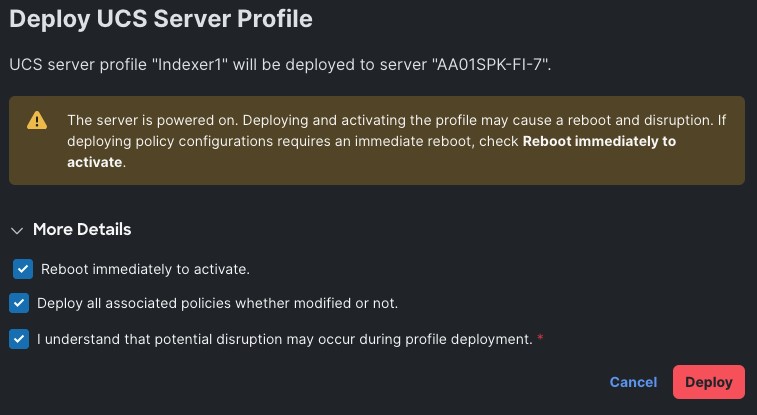
Step 4. Check the boxes and click Deploy to activate the server profile.
Step 5. Repeat steps 1 – 4 for each server profile.
Install and Configure Red Hat Enterprise Linux 9.6
This chapter contains the following:
● Install Red Hat Enterprise Linux (RHEL) 9.6
Note: Cisco Intersight enables you to install vMedia-based operating systems on managed servers in a data center. With this capability, you can perform an unattended OS installation on one or more Cisco UCS C-Series Standalone servers and Cisco Intersight Managed Mode (IMM) servers (Cisco UCS C-Series, Cisco UCS B-Series, and Cisco UCS X-Series) from your centralized data center through a simple process. For detailed instructions about adding images to the software repository and installing the operating system, see: https://intersight.com/help/saas/resources/OSinstallguide#os_install_steps
This chapter provides detailed procedures for installing Red Hat Enterprise Linux Server on Cisco UCS C225 and Cisco UCS C245 M8 servers. There are multiple ways to install the RHEL operating system. The installation procedure described in this deployment guide uses ISM automated workflow to install the operating system on all the servers through Intersight. For more information, see: https://intersight.com/help/saas/resources/installing_an_operating_system#performing_os_installation_in _cisco_mode
Note: In this solution, Red Hat Enterprise Linux version 9.6 (DVD/ISO) was utilized for OS the installation through Intersight Software Repository as explained in the following sections.
Install Red Hat Enterprise Linux (RHEL) 9.6
This section contains the following procedures:
● Procedure 1. Add OS Image Link
● Procedure 2. Add Server Configuration Utility Image
● Procedure 3. Install the Operating System
● Procedure 4. (Optional) Manual Operating System Install
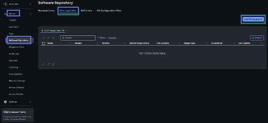
Procedure 1. Add OS Image Link
Step 1. Log into Intersight account.
Step 2. Go to Systems > Software Repository > OS Image Links tab and click the Add OS Image Link icon as shown below:
Step 3. Add the image source of the operating system along with details of the file share location and the protocol (CIFS/NFS/HTTPS) to the software repository.
Note: For this solution, we used HTTPS server and provided access of OS ISO as configured below:

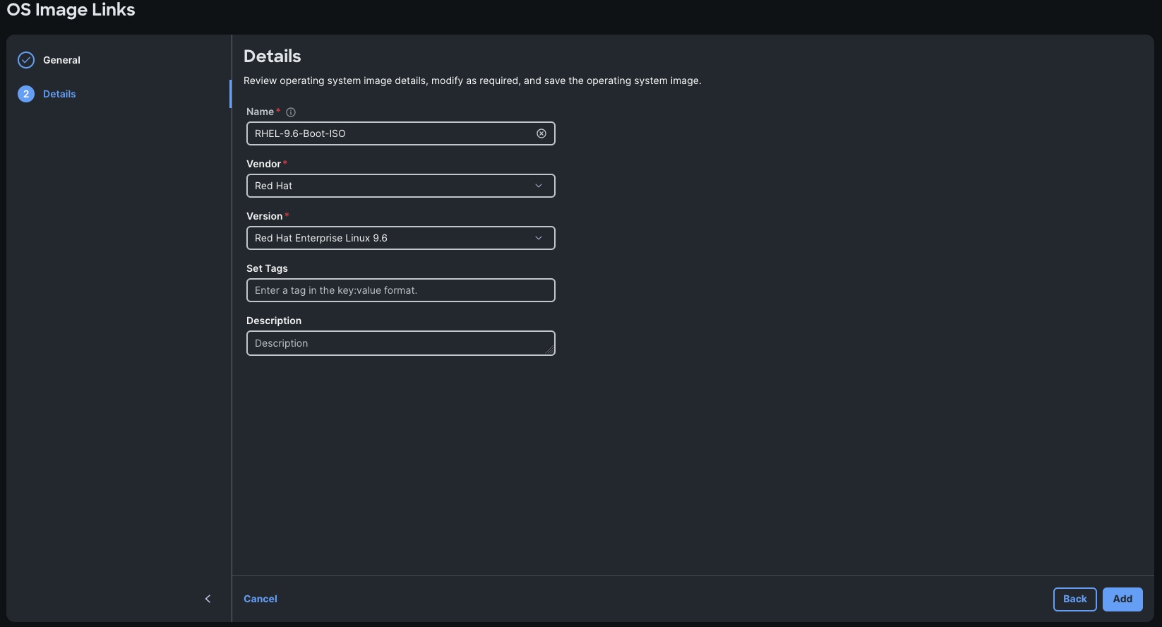
Step 4. Provide the details for Operating System image, modify as required, and save the Operating System image as shown below. Click Add.
Note: The software repository can be CIFS, NFS, or HTTPS and need not be publicly available. It should be accessible by Cisco IMC. Cisco IMC establishes vMedia connection with the software repository hosted ISO images. It is then mounted as Cisco IMC-managed vMedia files and booted to the server. For more information, see: https://intersight.com/help/saas/resources/adding_OSimage#about_this_task
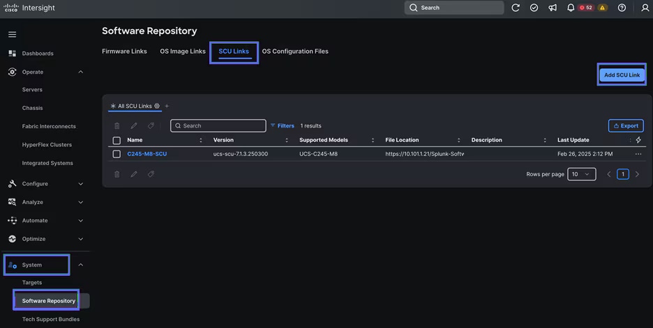
Procedure 2. Add Server Configuration Utility Image
Step 1. Log into Intersight Account.
Step 2. Go to Systems > Software Repository > SCU Links tab and click Add SCU Link as shown below:
Note: For this solution, we used HTTPS server and provided access of SCU ISO as configured below:

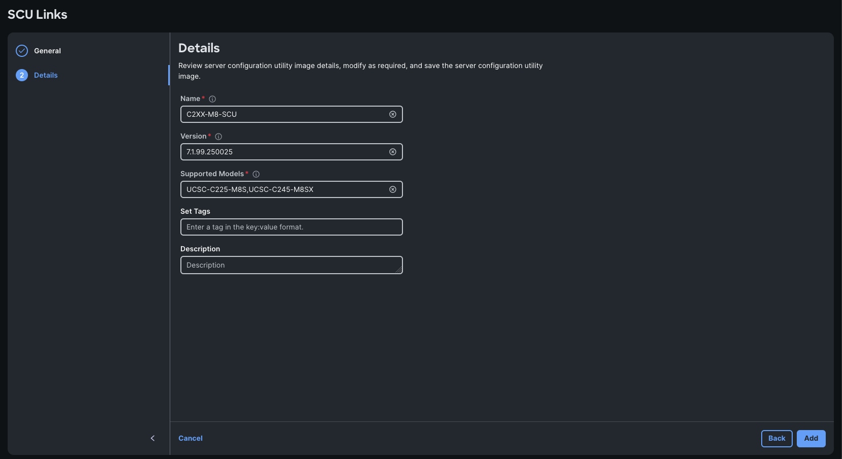
Step 3. Review the Server Configuration Utility image details, modify as required, and save the Server Configuration Utility image.
Procedure 3. Install the Operating System
Step 1. Log into Intersight Account.
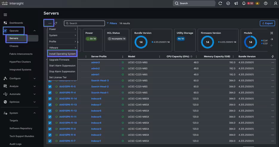
Step 2. Go to Operate > Servers > and then select a server.
Note: Using the ellipses in the upper left of the Servers screen allows you to select multiple servers to install the operating system in parallel. For this example, the installation will be on a single server.
Step 3. Click the ellipses and select Install Operating System as shown below:
Step 4. From the Install Operating System menu, make sure all the relevant servers are selected and click Next.
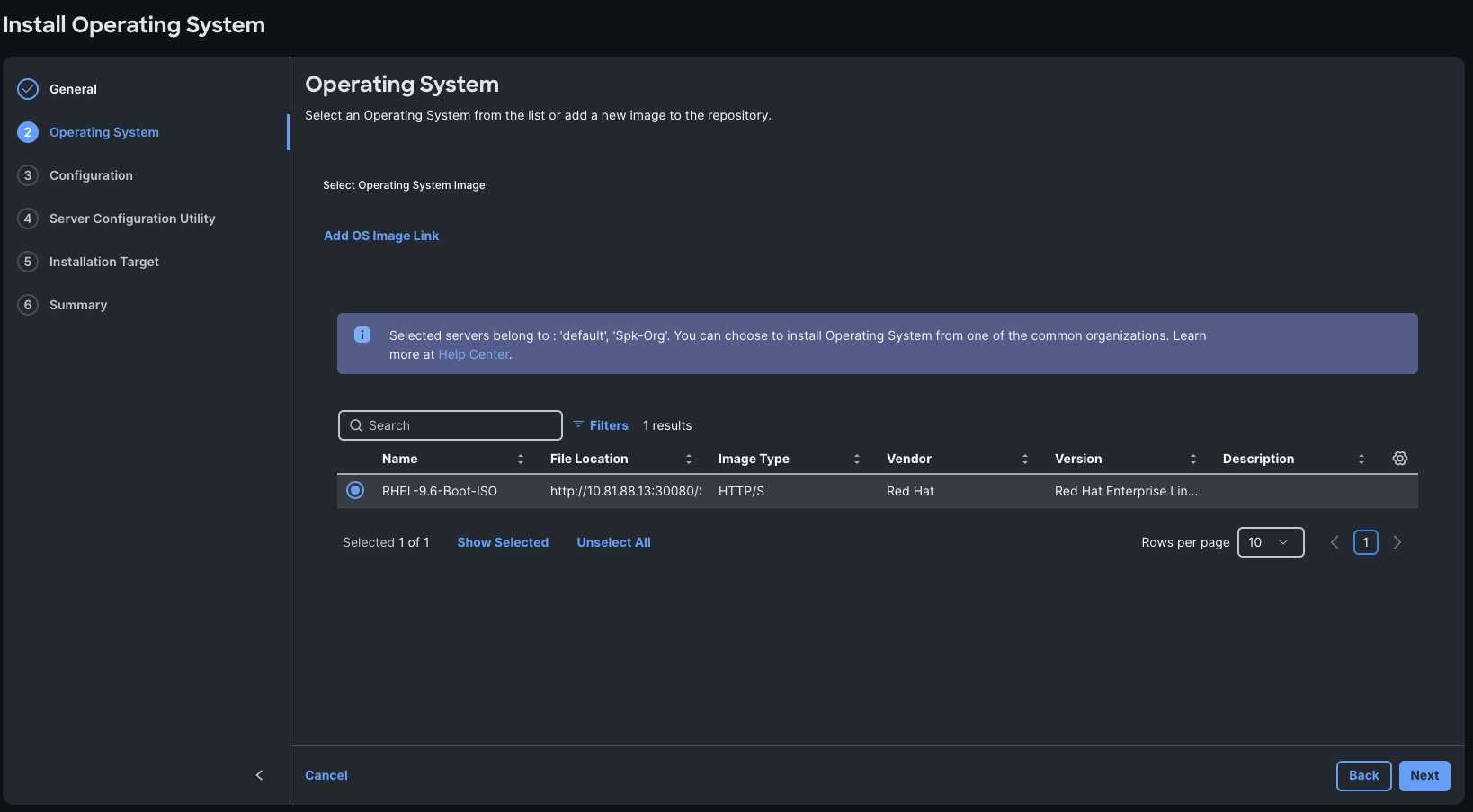
Step 5. Select the OS Image Link previously configured.
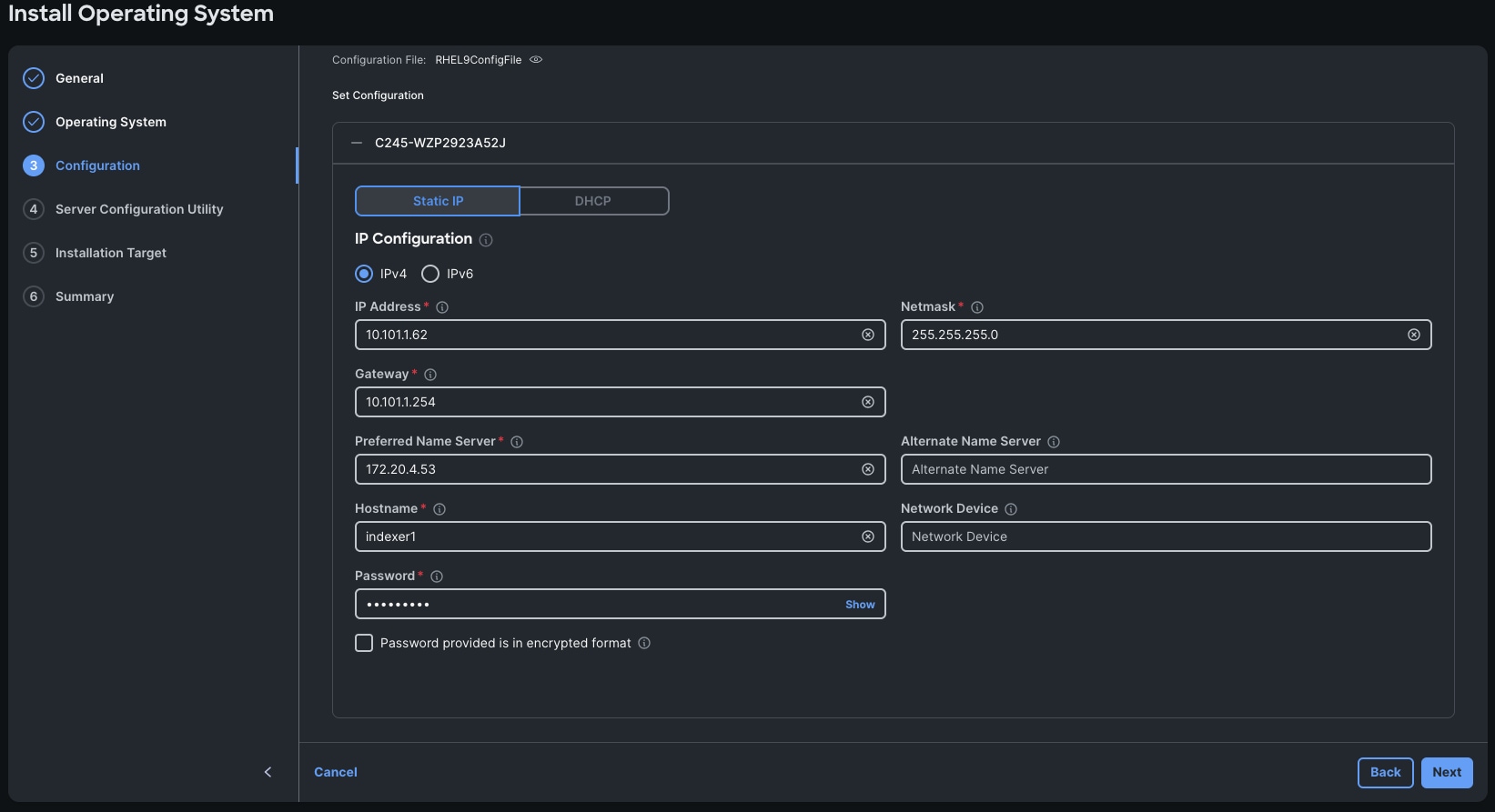
Step 6. From the Configuration menu, select the configuration sources.
Note: We used the default Cisco option and default RHEL9ConfigFile as shown below.
Note: You can either use custom or Cisco validated templates for selected Operating System version. For more information about Cisco validated templates, go to: https://us-east-1.intersight.com/help/saas/resources/installing_an_operating_system#performing_os_installation_in_ci sco_mode
Step 7. From the Configuration menu, provide the details for the RHEL host with the appropriate IP Address, Netmask, Gateway, Preferred Name Server, Hostname, and password then click Next.
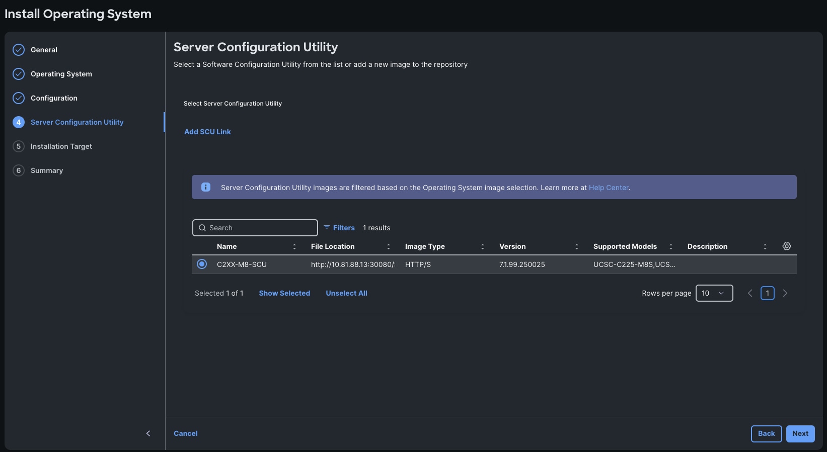
Step 8. From the Server Configuration Utility menu, select the SCU Link previously configured as shown below:
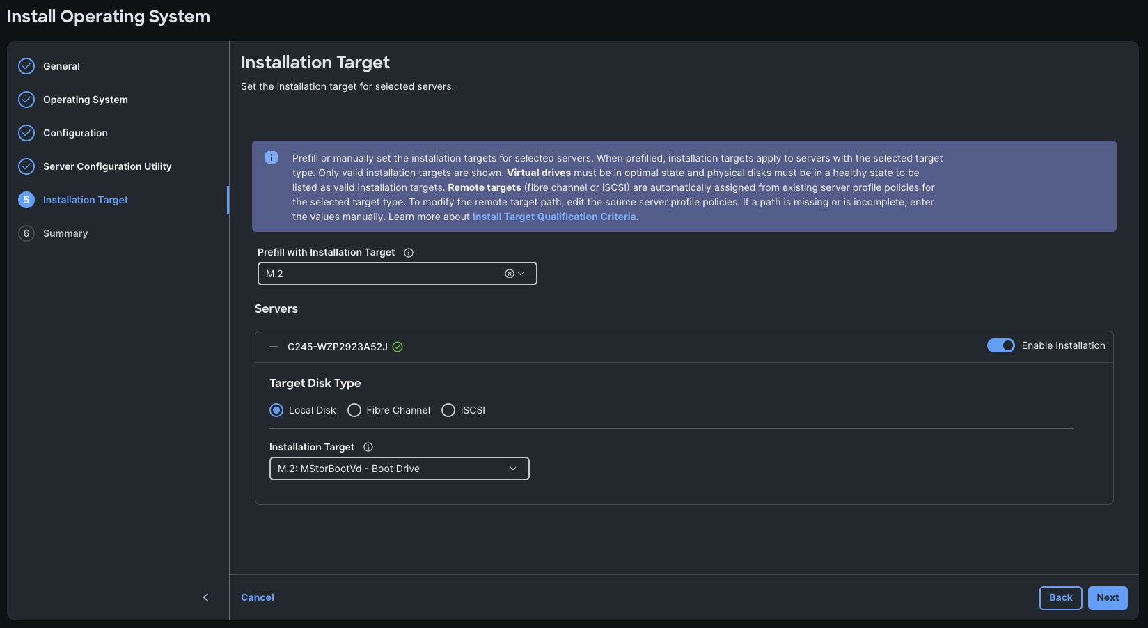
Step 9. From the Installation Target menu, select M.2 for the Installation target. When you select the M.2 option, all the servers will automatically detect the Boot Drive previously configured into the UCS Boot drive setup.

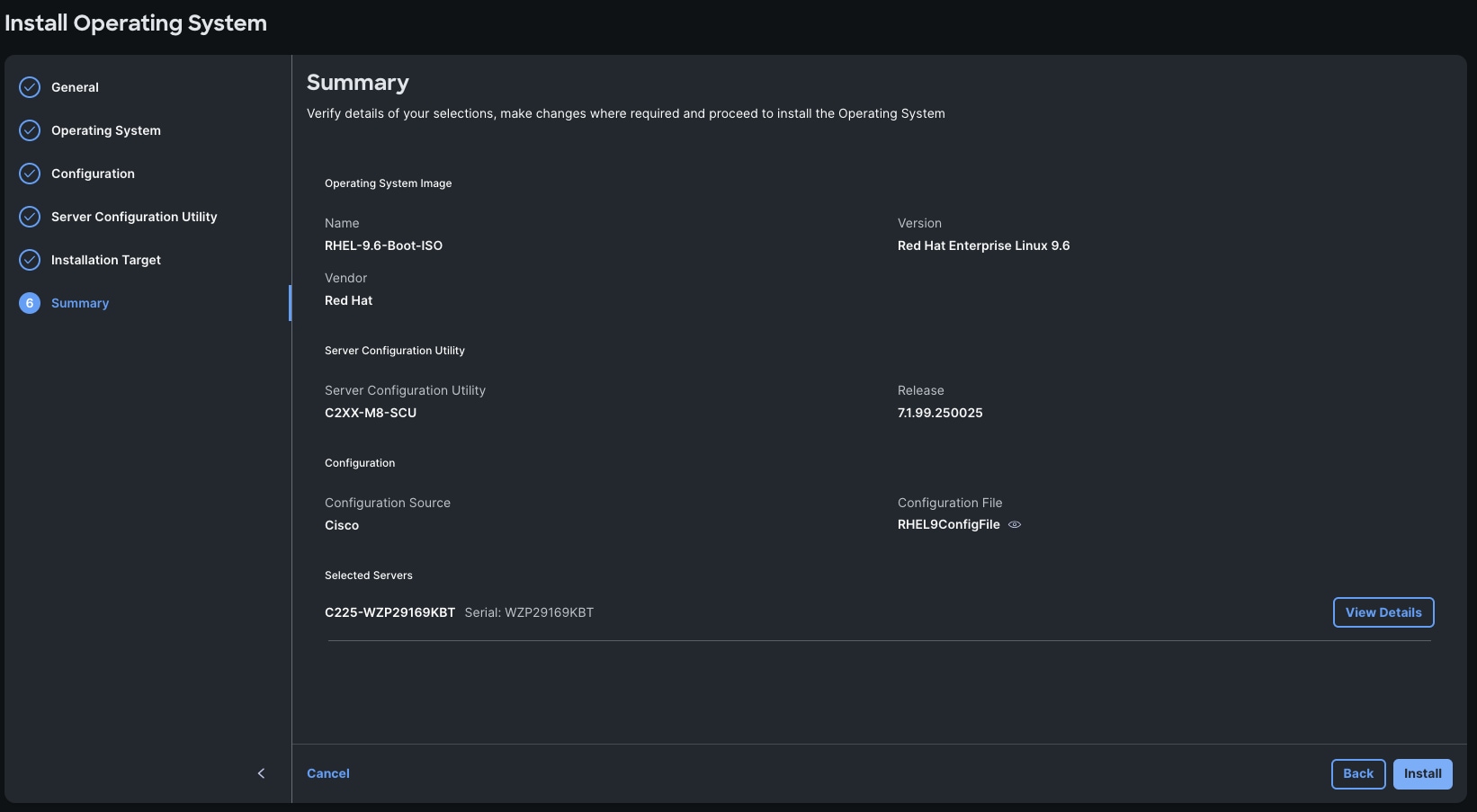
Step 10. Click Next and from the Summary menu, verify the details of your selections, make changes where required, and click Install to install the Operating System.
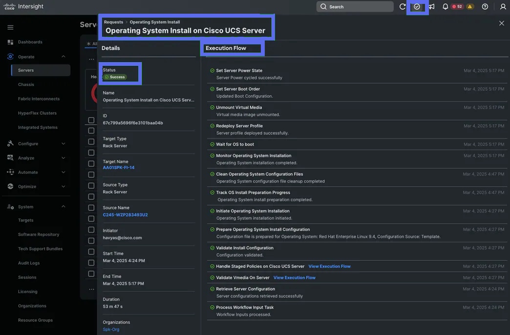
Step 11. To check the status of the task, click Request then click the individual task to see the execution flow as shown below:
Step 12. After the OS installation finishes, reboot the server, and complete the appropriate registration steps.
Procedure 4. (Optional) Manual Operating System Install Example
Note: This optional Manual installation of the OS can be performed through the virtual KVM console.
Step 1. Download the Red Hat Enterprise Linux 9.4 OS image and save the IOS file to local disk.
Step 2. Launch the vKVM console on your server by going to Cisco Intersight > Operate > Servers > click one of the server node and then from the Actions drop-down list select Launch vKVM.
Step 3. Click Accept security and open KVM. Click Virtual Media > vKVM-Mapped vDVD. Click Browse and map the RHEL ISO image, click Open and then click Map Drive. After mapping the iso file, click Power > Power Cycle System to reboot the server.
Step 4. During the server boot order, it detects the virtual media connected as RHEL ISO DVD media and it will launch the RHEL OS installer.
Step 5. Select language and for the Installation destination assign the local virtual drive. Apply the hostname and click Configure Network to configure any or all the network interfaces. Alternatively, you can configure only the “Public Network” in this step. You can configure additional interfaces as part of post OS install steps.
Tech tip: For an additional RPM package, we recommend selecting the “Customize Now” option and the relevant packages according to your environment.
Step 6. After the OS installation finishes, reboot the server, and complete the appropriate registration steps.
Step 7. Repeat steps 1-6 on all server nodes and install RHEL 9.6 on all the server nodes.
This section contains the following procedures:
● Procedure 1. Set up Remote Login from the Bastion
● Procedure 2. Disable the Linux Firewall
● Procedure 3. Disable SELinux
● Procedure 4. Upgrade Cisco UCS VIC Driver for Cisco UCS VIC
● Procedure 5. Configure Chrony
● Procedure 6. Disable Transparent Huge Pages
● Procedure 7. Configure File System Bastion, Controllers, Search Heads, and Indexers
● Procedure 8. Configure File System for Volume Servers
● Procedure 9. Run the Kubernetes Installer for Splunk POD
Procedure 1. Set up Remote Login from the Bastion
To manage all the nodes in a cluster from the Bastion node, SSH keys for remote access needs to be setup. This is required for the Kubernetes Installer for Splunk POD to function correctly.
This example deploys an open SSH key. It is strongly recommended to use a passphrase protected SSH key and the toolchain.
Step 1. Log into the Bastion:
# example
# ssh 10.10.10.10
Step 2. Run the ssh-keygen command to create both public and private keys on the admin node:
# ssh-keygen -N '' -f ~/.ssh/id_rsa
Step 3. Create an Ansible inventory file containing all hosts in the cluster. Example below:
[bastion]
10.10.10.10
[controllers]
10.10.10.11
10.10.10.12
10.10.10.13
# c225s
[searchheads]
10.10.10.21
10.10.10.22
10.10.10.23
# c245s indexers
[indexers]
10.10.10.31
10.10.10.32
10.10.10.33
# volume servers
[volumes]
10.10.10.41
10.10.10.42
10.10.10.43
10.10.10.44
Tech tip: A Splunk service account should be created on all hosts in the POD.
Step 4. Ensure that the service account user has passwordless sudo. This is required to install and manage Kubernetes.
# Example Ansible command
# ansible -i hosts all -m shell -a "sudo -l"
The result should look like this for all servers:
User splunk may run the following commands on host1:
(ALL) NOPASSWD: ALL
Step 5. When that is created, run the following command from the admin node to copy the public key id_rsa.pub to all the nodes of the cluster. ssh-copy-id appends the keys to the remote-hosts .ssh/authorized_keys
Tech tip: The user is not required to be splunk, but a service account is strongly recommended.
# Example Ansible command
# ansible -i hosts all -m authorized_key -a "user=splunk key=\"{{ lookup('file', lookup('env','HOME') + '/.ssh/id_rsa.pub') }}\" state=present" -k
Step 6. Enter the password of the remote host(s). Ensure the key has been deployed to all servers.
# Example Ansible command
# ansible -i hosts all -m ping
Step 7. Enable RHEL subscription for all machines:
# sudo subscription-manager register –username <password> --password <password> --autoattach
# sudo subscription-manager repos --enable codeready-builder-for-rhel-9-$(arch)-rpms
Procedure 2. Disable the Linux Firewall
Tech tip: Firewalld will interfere with the operation of Kubernetes and must be disabled.
Step 1. Run the following commands to disable the Linux firewall:
# Example Ansible command
# ansible all -m service -a "name=firewalld state=stopped enabled=false" -b
# Example shell command
# sudo systemctl stop firewalld && sudo systemctl disable firewalld
Procedure 3. Disable SELinux
Tech tip: SELinux must be disabled during the install procedure and cluster setup.
Step 1. SELinux can be disabled by editing /etc/selinux/config and changing the SELINUX line to SELINUX=disabled. To disable SELinux, run the following commands. It can also be disabled via the Ansible module:
# Example Ansible command
# ansible all -m selinux -a "state=disabled" -b
# reboot the hosts
# ansible all:\!bastion -m shell -a "shutdown -r now” -b
Note: This command may fail if SELinux is already disabled. This requires reboot to take effect.
Step 2. Reboot the machine, if needed for SELinux to be disabled in case it does not take effect. It can be checked using the following command:
# Example Ansible command
# ansible all -m shell -a "sestatus" -o -b
Procedure 4. Upgrade Cisco UCS VIC Driver for Cisco UCS VIC
The latest Cisco Network driver is required for performance and updates. The latest drivers can be downloaded from here: https://software.cisco.com/download/home/283862063/type/283853158/release/4.3(5e)
In the ISO image, the required driver can be located here: “\Network\Cisco\VIC\RHEL\RHEL9.4\kmodenic-4.8.0.0 1128.4.rhel9u4_5.14.0_427.13.1.x86_64.rpm”
Step 1. From a node connected to the Internet, download, extract, and transfer “kmod-enic-*.rpm to Bastion server.
Step 2. Copy the rpm on all nodes of the cluster using the following Ansible commands. For this example, the rpm is assumed to be in present working directory of the Bastion host:
# Example Ansible command
# ansible all -m copy -a "src=/root/kmod-enic-4.8.0.0-1128.4.rhel9u4_5.14.0_427.13.1.x86_64.rpm dest=/root/." -b
Step 3. Use the yum module to install the “enic” driver rpm file on all the nodes through Ansible:
# Example Ansible command
# ansible all -m shell -a "rpm -ivh =/root/kmod-enic-4.8.0.0-1128.4.rhel9u4_5.14.0_427.13.1.x86_64.rpm" -b
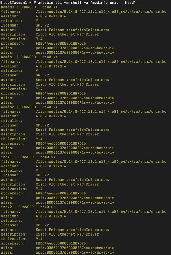
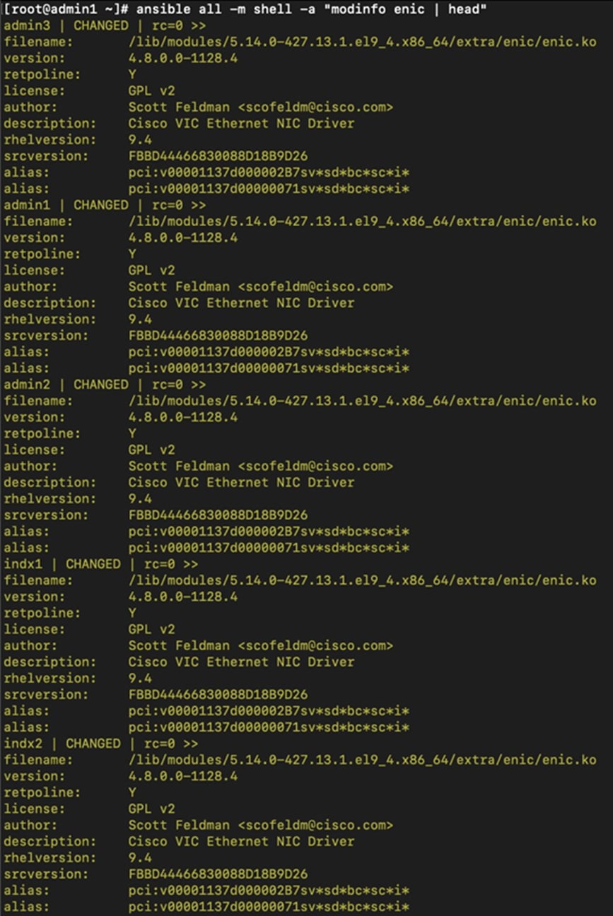
Step 4. Make sure that the above installed version of “kmod-enic” driver is being used on all nodes by running the command "modinfo enic" on all nodes:
Procedure 5. Configure Chrony
Step 1. Edit “/etc/chrony.conf” file:
# vi /etc/chrony.conf
pool <ntpserver> iburst
driftfile /var/lib/chrony/drift
makestep 1.0 3
rtcsync
#(optional) edit on ntpserver allow 10.29.134.0/24
local stratum 10 # local stratum 8 on ntpserver
keyfile /etc/chrony.keys
leapsectz right/UTC
logdir /var/log/chrony
Step 2. Copy “chrony.conf” file from the admin node to the “/etc/” of all nodes by running command below:
Example Ansible commands
# ansible all -m copy -a "src=/etc/chrony.conf dest=/etc/chrony.conf" -b
Step 3. Start Chrony service. Adjust timezone accordingly for the POD:
Example Ansible commands
# ansible all -m shell -a "timedatectl set-timezone America/Los_Angeles" -b
# ansible all -m service -a "name=chronyd state=running enabled=true" -b
# ansible all -m shell -a "hwclock --systohc" -b
Procedure 6. Disable Transparent Huge Pages
Step 1. Run the following command:
# ansible all -m shell -a "echo never > /sys/kernel/mm/transparent_hugepage/enabled"
# ansible all -m shell -a "echo never > /sys/kernel/mm/transparent_hugepage/defrag"
Step 2. Update the kernels to disable transparent huge pages permanently. This command should be run on all servers:
# /sbin/grubby --update-kernel=ALL --args=transparent_hugepage=never
Procedure 7. Configure File System for Bastion, Controllers, Search Heads, and Indexers
Cisco UCS C225 hosts ship with identical drive configurations, regardless of role. Each host has a RAID1 m2 boot volume, as configured above, and another RAID1 pairing of data drives. The Cisco UCS C245s that will host the indexers have 12 drives configured as RAID5 with a hot spare. All servers should have those volumes formatted as ext4 and mounted in the same location.
Step 1. Use fdisk to determine the data drive name. It is the larger volume and is probably /dev/sdb:
Example Shell command
# sudo fdisk -l | grep /dev/sdb
Step 2. Format data drive as ext4. This command is non-destructive by default. If a drive is already formatted, it will error without wiping the partition.
Example Shell command
# mkfs.ext4 /dev/sdb
Example Ansible command
# ansible -i hosts bastion:searchheads:controllers:indexers -m filesystem -a "fstype=ext4 dev=/dev/sdb" -b
Step 3. Update /etc/fstab and mount volumes:
Example Shell command
# sudo mkdir /data/shared
Append this line to /etc/fstab
# /dev/sdb /data/shared ext4 defaults,rw,relatime 0 0
# sudo mount -a
Verify the drive mounted correctly with df
Example Shell command
# df -h | grep shared
Example Ansible command
# ansible -i hosts bastion:searchheads:controllers:indexers -m shell -a "df -h | grep shared"
Procedure 8. Configure File System for Volume Servers
The Cisco UCS C245s that will host the volume servers have 24 drives configured as RAID5 with a hot spare. The volume servers should be using xfs instead of ext4.
Step 1. Use fdisk to determine the data drive name:
Example Shell command
# sudo fdisk -l | grep /dev/sdb
Step 2. Format data drive as xfs. This command is non-destructive by default. If a drive is already formatted, it will error without wiping the partition.
Example Shell command
# mkfs.xfs /dev/sdb
Example Ansible command
# ansible -i hosts volume -m filesystem -a “fstype=xfs dev=/dev/sdb” -b
Step 3. Update /etc/fstab and mount volumes.
Example Shell command
# sudo mkdir /data/storage
Append this line to /etc/fstab
# /dev/sdb /data/storage xfs defaults,noatime 0 0
Mount the drive
# sudo mount -a
Example Ansible Command
# ansible -i hosts volumes -m mount -a "src=/dev/sdb path=/data/storage fstype=xfs opts=defaults,noatime state=mounted" -b
Verify Drives are mounted correctly
Example Shell command
# df -h | grep shared
Example Ansible command
# ansible -i hosts volumes -m shell -a "df -h | grep storage"
Procedure 9. Run the Kubernetes Installer for Splunk POD
Step 1. Run the Splunk Kubernetes Installer once you have successfully prepared the hardware. The installer contains all necessary dependencies to install and run Splunk on Kubernetes on your recently configured hardware.
Step 2. Access the Splunk POD documentation here: https://help.splunk.com/?resourceId=Splunk_POD_overview and proceed with the steps detailed in the Deploy Splunk POD section to continue configuring the software required for Splunk POD.
Conclusion
Cisco UCS provides a tightly integrated platform combining compute, storage, and networking, which is purpose-built to support high-performance, scalable workloads like Splunk. This integration ensures predictable performance and high availability for Splunk Enterprise deployments. Deploying Splunk Enterprise on Cisco UCS servers managed by Cisco Intersight offers a unified, high-performance, and scalable infrastructure for operational analytics.
About the authors
Eugene Minchenko, Global Solutions Engineer Cisco Systems, Inc.
Eugene Minchenko is a Global Solution Architect at Cisco Systems with over 15 years of experience in architecting and implementing enterprise data center, AI and security solutions for global customers. He holds a master’s in computer science and specializes in sales engineering, developing reference architectures, and authoring technical documentation for data centers and cloud workloads.
Michael Guenther, Principal Software Engineer, Splunk LLC.
Michael Guenther is a Principal Engineer at Splunk responsible for the architecture of the Splunk POD solution. He has worked with numerous distributed systems. He joined Splunk in 2017 and has worked extensively on a wide range of Splunk products.
Michael Lusher, Software Engineer, Splunk LLC.
Michael Lusher is a Software Engineer at Splunk working on the Splunk POD solution. He joined Splunk in 2021 and has worked on a variety of Splunk products.
Acknowledgements
For their support and contribution to the design, validation, and creation of this Cisco Validated Design, the authors would like to thank
● Hardikkumar Vyas, Technical Marketing Engineer, Cisco Systems, Inc.
CVD Program
ALL DESIGNS, SPECIFICATIONS, STATEMENTS, INFORMATION, AND RECOMMENDATIONS (COLLECTIVELY, "DESIGNS") IN THIS MANUAL ARE PRESENTED "AS IS," WITH ALL FAULTS. CISCO AND ITS SUPPLIERS DISCLAIM ALL WARRANTIES, INCLUDING, WITHOUT LIMITATION, THE WARRANTY OF MERCHANTABILITY, FITNESS FOR A PARTICULAR PURPOSE AND NONINFRINGEMENT OR ARISING FROM A COURSE OF DEALING, USAGE, OR TRADE PRACTICE. IN NO EVENT SHALL CISCO OR ITS SUPPLIERS BE LIABLE FOR ANY INDIRECT, SPECIAL, CONSEQUENTIAL, OR INCIDENTAL DAMAGES, INCLUDING, WITHOUT LIMITATION, LOST PROFITS OR LOSS OR DAMAGE TO DATA ARISING OUT OF THE USE OR INABILITY TO USE THE DESIGNS, EVEN IF CISCO OR ITS SUPPLIERS HAVE BEEN ADVISED OF THE POSSIBILITY OF SUCH DAMAGES.
THE DESIGNS ARE SUBJECT TO CHANGE WITHOUT NOTICE. USERS ARE SOLELY RESPONSIBLE FOR THEIR APPLICATION OF THE DESIGNS. THE DESIGNS DO NOT CONSTITUTE THE TECHNICAL OR OTHER PROFESSIONAL ADVICE OF CISCO, ITS SUPPLIERS OR PARTNERS. USERS SHOULD CONSULT THEIR OWN TECHNICAL ADVISORS BEFORE IMPLEMENTING THE DESIGNS. RESULTS MAY VARY DEPENDING ON FACTORS NOT TESTED BY CISCO.
CCDE, CCENT, Cisco Eos, Cisco Lumin, Cisco Nexus, Cisco StadiumVision, Cisco TelePresence, Cisco WebEx, the Cisco logo, DCE, and Welcome to the Human Network are trademarks; Changing the Way We Work, Live, Play, and Learn and Cisco Store are service marks; and Access Registrar, Aironet, AsyncOS, Bringing the Meeting To You, Catalyst, CCDA, CCDP, CCIE, CCIP, CCNA, CCNP, CCSP, CCVP, Cisco, the Cisco Certified Internetwork Expert logo, Cisco IOS, Cisco Press, Cisco Systems, Cisco Systems Capital, the Cisco Systems logo, Cisco Unified Computing System (Cisco UCS), Cisco UCS B-Series Blade Servers, Cisco UCS C-Series Rack Servers, Cisco UCS S-Series Storage Servers, Cisco UCS X-Series, Cisco UCS Manager, Cisco UCS Management Software, Cisco Unified Fabric, Cisco Application Centric Infrastructure, Cisco Nexus 9000 Series, Cisco Nexus 7000 Series. Cisco Prime Data Center Network Manager, Cisco NX-OS Software, Cisco MDS Series, Cisco Unity, Collaboration Without Limitation, EtherFast, EtherSwitch, Event Center, Fast Step, Follow Me Browsing, FormShare, GigaDrive, HomeLink, Internet Quotient, IOS, iPhone, iQuick Study, LightStream, Linksys, MediaTone, MeetingPlace, MeetingPlace Chime Sound, MGX, Networkers, Networking Academy, Network Registrar, PCNow, PIX, PowerPanels, ProConnect, ScriptShare, SenderBase, SMARTnet, Spectrum Expert, StackWise, The Fastest Way to Increase Your Internet Quotient, TransPath, WebEx, and the WebEx logo are registered trade-marks of Cisco Systems, Inc. and/or its affiliates in the United States and certain other countries. (LDW_UP1)
All other trademarks mentioned in this document or website are the property of their respective owners. The use of the word partner does not imply a partnership relationship between Cisco and any other company. (0809R)
| Americas Headquarters Cisco Systems, Inc San Jose, CA |
Asia Pacific Headquarters Cisco System (USA) Ptd. Ltd. Singapore |
Europe Headquarters Cisco Systems International BV Amsterdam, The Netherlands |
| Cisco has more than 200 offices worldwide. Addresses, phone numbers, and fax numbers are listed on the Cisco Website at https://www.cisco.com/go/offices. |
||
| Cisco and the Cisco log are trademarks or registered trademarks of Cisco and/or its affiliates in the U.S. and other countries. To view a list of Cisco trademarks, go to this URL: https://www.cisco.com/go/trademarks. Third-party trademarks mentioned are the property of their respective owners. The use of the word partner does not imply a partnership between Cisco and any other company. (1110R) |
||