Cisco and Hitachi Adaptive Solutions for SAP HANA TDI
Available Languages

Cisco and Hitachi Adaptive Solutions for SAP HANA TDI
Deployment Guide for Cisco and Hitachi Converged Infrastructure with Cisco UCS Blade Servers, Cisco Nexus 9336C-FX2 Switches, Cisco MDS 9706 Fabric Switches, and Hitachi VSP G370 Storage Systems with SUSE Linux Enterprise Server for SAP Applications 12 SP4 and Red Hat Enterprise Linux 7.5
Published: April 2, 2019
Updated: February 7, 2020

About the Cisco Validated Design Program
The Cisco Validated Design (CVD) program consists of systems and solutions designed, tested, and documented to facilitate faster, more reliable, and more predictable customer deployments. For more information, go to:
http://www.cisco.com/go/designzone.
ALL DESIGNS, SPECIFICATIONS, STATEMENTS, INFORMATION, AND RECOMMENDATIONS (COLLECTIVELY, "DESIGNS") IN THIS MANUAL ARE PRESENTED "AS IS," WITH ALL FAULTS. CISCO AND ITS SUPPLIERS DISCLAIM ALL WARRANTIES, INCLUDING, WITHOUT LIMITATION, THE WARRANTY OF MERCHANTABILITY, FITNESS FOR A PARTICULAR PURPOSE AND NONINFRINGEMENT OR ARISING FROM A COURSE OF DEALING, USAGE, OR TRADE PRACTICE. IN NO EVENT SHALL CISCO OR ITS SUPPLIERS BE LIABLE FOR ANY INDIRECT, SPECIAL, CONSEQUENTIAL, OR INCIDENTAL DAMAGES, INCLUDING, WITHOUT LIMITATION, LOST PROFITS OR LOSS OR DAMAGE TO DATA ARISING OUT OF THE USE OR INABILITY TO USE THE DESIGNS, EVEN IF CISCO OR ITS SUPPLIERS HAVE BEEN ADVISED OF THE POSSIBILITY OF SUCH DAMAGES.
THE DESIGNS ARE SUBJECT TO CHANGE WITHOUT NOTICE. USERS ARE SOLELY RESPONSIBLE FOR THEIR APPLICATION OF THE DESIGNS. THE DESIGNS DO NOT CONSTITUTE THE TECHNICAL OR OTHER PROFESSIONAL ADVICE OF CISCO, ITS SUPPLIERS OR PARTNERS. USERS SHOULD CONSULT THEIR OWN TECHNICAL ADVISORS BEFORE IMPLEMENTING THE DESIGNS. RESULTS MAY VARY DEPENDING ON FACTORS NOT TESTED BY CISCO.
CCDE, CCENT, Cisco Eos, Cisco Lumin, Cisco Nexus, Cisco StadiumVision, Cisco TelePresence, Cisco WebEx, the Cisco logo, DCE, and Welcome to the Human Network are trademarks; Changing the Way We Work, Live, Play, and Learn and Cisco Store are service marks; and Access Registrar, Aironet, AsyncOS, Bringing the Meeting To You, Catalyst, CCDA, CCDP, CCIE, CCIP, CCNA, CCNP, CCSP, CCVP, Cisco, the Cisco Certified Internetwork Expert logo, Cisco IOS, Cisco Press, Cisco Systems, Cisco Systems Capital, the Cisco Systems logo, Cisco Unified Computing System (Cisco UCS), Cisco UCS B-Series Blade Servers, Cisco UCS C-Series Rack Servers, Cisco UCS S-Series Storage Servers, Cisco UCS Manager, Cisco UCS Management Software, Cisco Unified Fabric, Cisco Application Centric Infrastructure, Cisco Nexus 9000 Series, Cisco Nexus 7000 Series. Cisco Prime Data Center Network Manager, Cisco NX-OS Software, Cisco MDS Series, Cisco Unity, Collaboration Without Limitation, EtherFast, EtherSwitch, Event Center, Fast Step, Follow Me Browsing, FormShare, GigaDrive, HomeLink, Internet Quotient, IOS, iPhone, iQuick Study, LightStream, Linksys, MediaTone, MeetingPlace, MeetingPlace Chime Sound, MGX, Networkers, Networking Academy, Network Registrar, PCNow, PIX, PowerPanels, ProConnect, ScriptShare, SenderBase, SMARTnet, Spectrum Expert, StackWise, The Fastest Way to Increase Your Internet Quotient, TransPath, WebEx, and the WebEx logo are registered trademarks of Cisco Systems, Inc. and/or its affiliates in the United States and certain other countries.
All other trademarks mentioned in this document or website are the property of their respective owners. The use of the word partner does not imply a partnership relationship between Cisco and any other company. (0809R)
© 2020 Cisco Systems, Inc. All rights reserved.
Table of Contents
Deployment Hardware and Software
Hardware and Software Versions
Cisco Nexus 9000 Series Switch Network Configuration
Cisco Nexus 9000 Initial Configuration
Enable Appropriate Cisco Nexus 9000 Series Switches Features and Settings
Create VLANs for SAP HANA Traffic
Configure Virtual Port-Channel Domain
Configure Network Interfaces for the VPC Peer Links
Configure vPCs with Cisco UCS Fabric Interconnect
Configuration of Hitachi Storage
Create Dynamic Provisioning Pools
Provision the LUNS (Virtual Volumes)
Create Virtual Volumes for the Operating System LUNS and Map Ports
Create Virtual Volumes for HANA Shared File System and Map Ports
Create Virtual Volumes for Log LUNs and Map Ports
Create Virtual Volumes for Data LUNs and Map Ports
Cisco UCS Configuration Overview
Upgrade Cisco UCS Manager Software to Version 4.0(1c)
Initial Setup of Cisco UCS 6332-16UP Fabric Interconnects
Cisco UCS 6332-16UP Fabric Interconnect B
Configure Ethernet Uplink Ports
Add Block of IP Addresses for KVM Access
Update Default Maintenance Policy
Configure Cisco UCS LAN Connectivity
Set Jumbo Frames in Cisco UCS Fabric
Create LAN Uplink Port Channels
Configure Cisco UCS SAN Configurations
Create Boot Policy for SAN Boot
Create Service Profile Templates for SAP HANA Scale Up Servers
Create Service Profile from the Template
Configure Cisco MDS 9706 Switches
Cisco MDS Initial Configuration Dialogue
Cisco MDS Switch Configuration
Configure Fibre Channel Ports and Port Channels
Create and Configure Fiber Channel Zoning
Associate Service Profile to Cisco UCS Server
SLES for SAP 12 SP4 OS Installation
Network Services Configuration
SLES for SAP 12 SP 4 System Update and OS Customization
Install Cisco eNIC and fNIC Driver
Red Hat Enterprise Linux for SAP Solutions 7.5 OS Installation
Network Services Configuration
RHEL 7.5 System Update and OS Customization for SAP HANA
Install Cisco eNIC and fNIC Driver
Configure HANA Persistent Storage Volume Configuration
SAP HANA Persistent Storage Volume Configuration for Scale-Up Deployments
Configuration Example on SUSE Linux Enterprise Server for SAP Applications
Configuration Example on Red Hat Enterprise Linux
Certified SAP HANA Hardware Directory
Cisco Validated Designs consist of systems and solutions that are designed, tested, and documented to facilitate and improve customer deployments. These designs incorporate a wide range of technologies and products into a portfolio of solutions that have been developed to address the business needs of our customers.
Cisco and Hitachi are working together to deliver a converged infrastructure solution that helps enterprise businesses meet the challenges of today and position themselves for the future. Leveraging decades of industry expertise and superior technology, this Cisco CVD offers a resilient, agile, and flexible foundation for today’s businesses. In addition, the Cisco and Hitachi partnership extends beyond a single solution, enabling businesses to benefit from their ambitious roadmap of evolving technologies such as advanced analytics, IoT, cloud, and edge capabilities. With Cisco and Hitachi, organizations can confidently take the next step in their modernization journey and prepare themselves to take advantage of new business opportunities enabled by innovative technology.
This document explains the deployment of the Cisco and Hitachi Adaptive Solutions for SAP HANA Tailored Data Center Integration, as it was described in Cisco and Hitachi Adaptive Solutions for SAP HANA Tailored Data Center Integration Design Guide. The recommended solution architecture is built on Cisco Unified Computing System (Cisco UCS) using the unified software release to support the Cisco UCS hardware platforms for Cisco UCS B-Series blade servers, Cisco UCS 6300 Fabric Interconnects, Cisco Nexus 9000 Series switches, Cisco MDS Fiber channel switches, and Hitachi VSP controllers. This architecture supports Red Hat Enterprise Linux and SUSE Linux Enterprise Server for SAP Applications.
Introduction
Enterprise data centers have a need for scalable and reliable infrastructure that can be implemented in an intelligent, policy driven manner. This implementation needs to be easy to use, and deliver application agility, so IT teams can provision applications quickly and resources can be scaled up (or down) in minutes.
Cisco and Hitachi Adaptive Solutions for SAP HANA Tailored Data Center Integration provides a best practice datacenter architecture built on the collaboration of Hitachi Vantara and Cisco to meet the needs of enterprise customers. The solution provides Orchestrate efficiency across the data path with an intelligent system that helps anticipate and navigate challenges as you grow. The architecture builds a self-optimizing data center that automatically spreads workloads across devices to ensure consistent utilization and performance. The solution helps organization to effectively plan infrastructure growth and eliminate the budgeting guesswork with predictive risk profiles that identify historical trends.
Organizations experience a 5-year ROI of 528% with Cisco UCS Integrated Infrastructure solutions, Businesses experience 48% lower IT infrastructure costs with Cisco UCS Integrated Infrastructure solutions. Organizations can realize a 5-year total business benefit of $20.4M per organization with Cisco UCS Integrated Infrastructure solutions. The break-even period with Cisco UCS Integrated Infrastructure solutions is nine months. Businesses experience 67% lower ongoing administrative and management costs with Cisco UCS Manager (UCSM). For more information please refer to IDC #US41084916 2016
This architecture is composed of the Hitachi Virtual Storage Platform (VSP) connecting through the Cisco MDS multilayer switches to Cisco Unified Computing System (Cisco UCS), and further enabled with the Cisco Nexus family of switches.
Audience
The audience for this document includes, but is not limited to; sales engineers, field consultants, professional services, IT managers, partner engineers, and customers who want to modernize their infrastructure to meet SLAs and the business needs at any scale.
Purpose of this Document
This document provides a step by step configuration and implementation guide for the Cisco and Hitachi Adaptive Solutions for Converged Infrastructure solution. This solution features a validated reference architecture composed of:
· Cisco UCS Compute
· Cisco Nexus Switches
· Cisco Multilayer SAN Switches
· Hitachi Virtual Storage Platform
· SUSE Enterprise Linux and Red Hat Enterprise Linux Operating System
· SAP HANA
For the design decisions and technology discussion of the solution, please refer to the Cisco and Hitachi Adaptive Solutions for SAP HANA Tailored Data Center Integration Design Guide.
Solution Design
Architecture
Cisco and Hitachi Adaptive Solutions for SAP HANA Tailored Data Center Integration provides an end-to-end architecture with Cisco Compute, Networking and Hitachi Storage that demonstrate support for multiple SAP HANA workloads with high availability and secure multi-tenancy. The architecture is built around the Cisco Unified Computing System(UCS) and the Hitachi Virtual Storage Platform(VSP) connected together by Cisco MDS Multilayer SAN Switches, and further enabled with Cisco Nexus Switches. These components come together to form a powerful and scalable design, built on the best practices of Cisco and Hitachi to create an ideal platform for running a variety of enterprise workloads with confidence. Figure 1 illustrates the physical topology of the Cisco and Hitachi Adaptive Solutions for SAP HANA Tailored Data Center Integration.
Figure 1 Cisco and Hitachi Adaptive Solutions for SAP HANA Tailored Data Center Integration Architecture

The components of this integrated architecture shown in Figure 1 are:
· Cisco Nexus 9336C-FX2 – 100Gb capable, LAN connectivity to the Cisco UCS compute resources.
· Cisco UCS 6332-16UP Fabric Interconnect – Unified management of Cisco UCS compute, and the compute’s access to storage and networks.
· Cisco UCS B200 M5 – High powered, versatile blade server with two CPU for SAP HANA
· Cisco UCS B480 M5 – High powered, versatile blade server with four CPU for SAP HANA
· Cisco MDS 9706 – 16Gbps Fiber Channel connectivity within the architecture, as well as interfacing to resources present in an existing data center.
· Hitachi VSP G370 – Mid-range, high performance storage subsystem with optional all-flash configuration
· Cisco UCS Manager – Management delivered through the Fabric Interconnect, providing stateless compute, and policy driven implementation of the servers managed by it.
Hardware and Software Versions
Table 1 lists the validated hardware and software versions used for this solution. Configuration specifics are given in this deployment guide for the devices and versions listed in the following tables. Component and software version substitution from what is listed is considered acceptable within this reference architecture, but substitution will need to comply with the hardware and software compatibility matrices from both Cisco and Hitachi, please refer to the following documentation:
Cisco UCS Hardware Compatibility Matrix:
https://ucshcltool.cloudapps.cisco.com/public/
Cisco Nexus and MDS Interoperability Matrix:
Cisco Nexus Recommended Releases for Nexus 9K:
https://www.cisco.com/c/en/us/td/docs/switches/datacenter/nexus9000/sw/recommended_release/b_Minimum_and_Recommended_Cisco_NX-OS_Releases_for_Cisco_Nexus_9000_Series_Switches.html
Cisco MDS Recommended Releases:
https://www.cisco.com/c/en/us/td/docs/switches/datacenter/mds9000/sw/b_MDS_NX-OS_Recommended_Releases.html
Hitachi Vantara Interoperability:
https://support.hitachivantara.com/en_us/interoperability.html
In addition, any substituted hardware or software may have different configurations from what is detailed in this guide and will require a thorough evaluation of the substituted product reference documents.
Table 1 Validated Hardware and Software
| Component |
Software Version/Firmware Version |
|
| Network |
Cisco Nexus 9336C-FX2 |
7.0(3)I7(5a) |
| Compute |
Cisco UCS Fabric Interconnect 6332 |
4.0(1c) |
| Cisco UCS 2304 IOM |
4.0(1c) |
|
| Cisco UCS B480 M5 Blade Server |
4.0(1c) |
|
| Cisco UCS B200 M5 Blade Server |
4.0(1c) |
|
| SUSE Linux Enterprise Server for SAP Applications |
SLES for SAP 12 SP4 |
|
| Red Hat Enterprise Linux for SAP Solutions |
RHEL 7.5 |
|
| Storage |
Hitachi VSP G370 |
88-02-03-60/00 |
| Cisco MDS 9706 (DS-X97-SF1-K9 & DS-X9648-1536K9) |
8.3(1) |
|
Configuration Guidelines
This information in this section is intended to enable you to fully configure the customer environment. In this process, various steps require you to insert customer-specific naming conventions, IP addresses, and VLAN schemes, as well as to record appropriate MAC addresses. Table 2 lists the configuration variables that are used throughout this document. This table can be completed based on the specific site variables and used in implementing the document configuration steps.
The Cisco UCS Fabric Interconnects are similarly configured. Additionally, this document details the steps for provisioning multiple Cisco UCS hosts, and these are identified sequentially: HANA-Server01, HANA-Server02, and so on. Finally, to indicate that you should include information pertinent to your environment in a given step, <text> appears as part of the command structure. Review the following example for the network port vlan create command:
Usage:
network port vlan create ?
[-node] <nodename> Node
{ [-vlan-name] {<netport>|<ifgrp>} VLAN Name
| -port {<netport>|<ifgrp>} Associated Network Port
[-vlan-id] <integer> } Network Switch VLAN Identifier
Example:
network port vlan –node <node01> -vlan-name i0a-<vlan id>
Table 2 Configuration Variables
| Variable |
Description |
Customer Implementation Value |
| <<var_nexus_A_hostname>> |
Cisco Nexus 9336C-FX2-A host name |
|
| <<var_nexus_A_mgmt0_ip>> |
Out-of-band Cisco Nexus 9336C-FX2-A management IP address |
|
| <<var_nexus_B_hostname>> |
Cisco Nexus 9336C-FX2-B host name |
|
| <<var_nexus_B_mgmt0_ip>> |
Out-of-band Cisco Nexus 9336C-FX2-B management IP address |
|
| <<var_mgmt_mask>> |
Out-of-band management network netmask |
|
| <<var_mgmt_gateway>> |
Out-of-band management network default gateway |
|
| <<var_ucs_clustername>> |
Cisco UCS Manager cluster host name |
|
| <<var_ucsa_mgmt_ip>> |
Cisco UCS 6332-16UP-A out-of-band management IP address |
|
| <<var_ucsb_mgmt_ip>> |
Cisco UCS 6332-16UP-B out-of-band management IP address |
|
| <<var_ucs_cluster_ip>> |
Cisco UCS Manager cluster IP address |
|
| <<var_hitachi_svp_ip>> |
Out-of-band management IP for Hitachi storage management network |
|
| <<var_hitachi_controller-1_mgmt_ip>> |
Out-of-band management IP for Hitachi storage Controller 1 |
|
| <<var_hitachi_controller-2_mgmt_ip>> |
Out-of-band management IP for Hitachi storage Controller 2 |
|
| <<var_dns_domain_name>> |
DNS domain name |
|
| <<var_nameserver_ip>> |
DNS server IP(s) |
|
| <<var_global_ntp_server_ip>> |
NTP server IP address |
|
| <<var_mds-a_name>> |
Cisco MDS 9706 A hostname |
|
| <<var_mds-a_ip>> |
Cisco MDS 9706 A Management IP Address |
|
| <<var_mds-b_name>> |
Cisco MDS 9706 B hostname |
|
| <<var_mds-b_ip>> |
Cisco MDS 9706 B Management IP Address |
|
| <<var_nexus_vpc_domain_id>> |
Unique Cisco Nexus switch VPC domain ID for Cisco Nexus 9336C-FX2 Switch pair |
|
| <<var_mgmt_vlan_id>> |
Management Network VLAN |
|
| <<var_backup_vlan_id>> |
Backup Network for HANA VLAN ID |
|
| <<var_client_vlan_id>> |
Client Network for HANA VLAN ID |
|
| <<var_appserver_vlan_id>> |
Application Server Network for HANA VLAN ID |
|
| <<var_datasource_vlan_id>> |
Data source Network for HANA VLAN ID |
|
| <<var_replication_vlan_id>> |
Replication Network for HANA VLAN ID |
|
| <<var_fc-pc_a_id>> |
Fiber Channel - Port Channel ID for MDS A |
|
| <<var_fc-pc_b_id>> |
Fiber Channel - Port Channel ID for MDS B |
|
| <<var_san_a_id>> |
VSAN ID for MDS A |
|
| <<var_san_b_id>> |
VSAN ID for MDS B |
|
Physical Cabling
This section explains the cabling examples used in the validated environment. To make connectivity clear in this example, the tables include both the local and remote port locations.
This document assumes that out-of-band management ports are plugged into an existing management infrastructure at the deployment site. The upstream network from the Nexus 9336C-FX2 switches is out of scope of this document, with only the assumption that these switches will connect to the upstream switch or switches with a virtual Port Channel (vPC).
Figure 2 shows the cabling configuration used in this validated design.
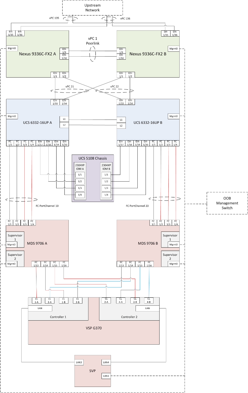
Table 3 through Table 8 provide the details of the specific port connections with the cables used in this deployment guide.
Table 3 Cisco Nexus 9336C-FX2 A Cabling Information
| Local Device |
Local Port |
Connection |
Remote Device |
Remote Port |
| Cisco Nexus 9336C-FX2 A
|
Eth1/1 |
40GbE |
Cisco UCS fabric interconnect A |
1/33 |
| Eth1/2 |
40GbE |
Cisco UCS fabric interconnect B |
1/33 |
|
| Eth1/9 |
40GbE |
Nx9336C-FX2-B |
1/9 |
|
| Eth1/10 |
40GbE |
Nx9336C-FX2-B |
1/10 |
|
| Eth1/31 |
40GbE |
Cisco UCS fabric interconnect A (optional) |
1/31 |
|
| Eth1/32 |
40GbE |
Cisco UCS fabric interconnect B (optional) |
1/31 |
|
| Eth1/35 |
40GbE |
Customer Uplink Switch -A |
Any |
|
| Eth1/36 |
40GbE |
Customer Uplink Switch -B |
Any |
|
| MGMT0 |
GbE |
Customer Management Switch |
Any |
Table 4 Cisco Nexus 9336C-FX2 A Cabling Information
| Local Device |
Local Port |
Connection |
Remote Device |
Remote Port |
| Cisco Nexus 9336C-FX2 B
|
Eth1/1 |
40GbE |
Cisco UCS fabric interconnect A |
1/34 |
| Eth1/2 |
40GbE |
Cisco UCS fabric interconnect B |
1/34 |
|
| Eth1/9 |
40GbE |
Nx9336C-FX2-B |
1/9 |
|
| Eth1/10 |
40GbE |
Nx9336C-FX2-B |
1/10 |
|
| Eth1/31 |
40GbE |
Cisco UCS fabric interconnect A (optional) |
1/32 |
|
| Eth1/32 |
40GbE |
Cisco UCS fabric interconnect B (optional) |
1/32 |
|
| Eth1/35 |
40GbE |
Customer Uplink Switch -A |
Any |
|
| Eth1/36 |
40GbE |
Customer Uplink Switch -B |
Any |
|
| MGMT0 |
GbE |
Customer Management Switch |
Any |
Table 5 Cisco UCS 6332-16UP A Cabling Information
| Local Device |
Local Port |
Connection |
Remote Device |
Remote Port |
| Cisco UCS 6332-16UP FI A
|
Eth1/1 |
FC uplink |
MDS-A |
1/1 |
| Eth1/2 |
FC uplink |
MDS-A |
1/2 |
|
| Eth1/3 |
FC uplink |
MDS-A |
1/3 |
|
| Eth1/4 |
FC uplink |
MDS-A |
1/4 |
|
| Eth1/17 |
40GbE |
Cisco UCS 5108 Chassis 1 – IOM A |
1/1 |
|
| Eth1/18 |
40GbE |
Cisco UCS 5108 Chassis 1 – IOM A |
1/2 |
|
| Eth1/19 |
40GbE |
Cisco UCS 5108 Chassis 1 – IOM A |
1/3 |
|
| Eth1/20 |
40GbE |
Cisco UCS 5108 Chassis 1 – IOM A |
1/4 |
|
| Eth1/21 |
40GbE |
Cisco UCS 5108 Chassis 1 – IOM A |
1/1 |
|
| Eth1/22 |
40GbE |
Cisco UCS 5108 Chassis 1 – IOM A |
1/2 |
|
| Eth1/23 |
40GbE |
Cisco UCS 5108 Chassis 1 – IOM A |
1/3 |
|
| Eth1/24 |
40GbE |
Cisco UCS 5108 Chassis 1 – IOM A |
1/4 |
|
| Eth1/31 |
40GbE |
Nx9336C-FX2-A (optional) |
1/31 |
|
| Eth1/32 |
40GbE |
Nx9336C-FX2-B (optional) |
1/31 |
|
| Eth1/33 |
40GbE |
Nx9336C-FX2-A |
1/1 |
|
| Eth1/34 |
40GbE |
Nx9336C-FX2-B |
1/1 |
|
| MGMT0 |
GbE |
Customer Management Switch |
Any |
|
| L1 |
GbE |
Cisco UCS fabric interconnect B |
L1 |
|
| L2 |
GbE |
Cisco UCS fabric interconnect B |
L2 |
Table 6 Cisco UCS 6332-16UP B Cabling Information
| Local Device |
Local Port |
Connection |
Remote Device |
Remote Port |
| Cisco UCS 6332-16UP FI B
|
Eth1/1 |
FC uplink |
MDS-B |
1/1 |
| Eth1/2 |
FC uplink |
MDS-B |
1/2 |
|
| Eth1/3 |
FC uplink |
MDS-B |
1/3 |
|
| Eth1/4 |
FC uplink |
MDS-B |
1/4 |
|
| Eth1/17 |
40GbE |
Cisco UCS 5108 Chassis 1 – IOM B |
1/1 |
|
| Eth1/18 |
40GbE |
Cisco UCS 5108 Chassis 1 – IOM B |
1/2 |
|
| Eth1/19 |
40GbE |
Cisco UCS 5108 Chassis 1 – IOM B |
1/3 |
|
| Eth1/20 |
40GbE |
Cisco UCS 5108 Chassis 1 – IOM B |
1/4 |
|
| Eth1/21 |
40GbE |
Cisco UCS 5108 Chassis 1 – IOM B |
1/1 |
|
| Eth1/22 |
40GbE |
Cisco UCS 5108 Chassis 1 – IOM B |
1/2 |
|
| Eth1/23 |
40GbE |
Cisco UCS 5108 Chassis 1 – IOM B |
1/3 |
|
| Eth1/24 |
40GbE |
Cisco UCS 5108 Chassis 1 – IOM B |
1/4 |
|
| Eth1/31 |
40GbE |
Nx9336C-FX2-A (optional) |
1/32 |
|
| Eth1/32 |
40GbE |
Nx9336C-FX2-B (optional) |
1/32 |
|
| Eth1/33 |
40GbE |
Nx9336C-FX2-A |
1/2 |
|
| Eth1/34 |
40GbE |
Nx9336C-FX2-B |
1/2 |
|
| MGMT0 |
GbE |
Customer Management Switch |
Any |
|
| L1 |
GbE |
Cisco UCS fabric interconnect B |
L1 |
|
| L2 |
GbE |
Cisco UCS fabric interconnect B |
L2 |
Table 7 Cisco MDS 9706 A Cabling Information
| Local Device |
Local Port |
Connection |
Remote Device |
Remote Port |
| Cisco MDS 9706 A
|
Eth1/1 |
FC uplink |
Cisco UCS fabric interconnect A |
1/1 |
| Eth1/2 |
FC uplink |
Cisco UCS fabric interconnect A |
1/2 |
|
| Eth1/3 |
FC uplink |
Cisco UCS fabric interconnect A |
1/3 |
|
| Eth1/4 |
FC uplink |
Cisco UCS fabric interconnect A |
1/4 |
|
| Eth1/13 |
FC uplink |
Hitachi VSP G370 – Controller 1 |
CL1-A |
|
| Eth1/14 |
FC uplink |
Hitachi VSP G370 – Controller 1 |
CL1-B |
|
| Eth1/15 |
FC uplink |
Hitachi VSP G370 – Controller 2 |
CL2-A |
|
| Eth1/16 |
FC uplink |
Hitachi VSP G370 – Controller 2 |
CL2-B |
|
| MGMT0 |
GbE |
Customer Management Switch |
Any |
Table 8 Cisco MDS 9706 B Cabling Information
| Local Device |
Local Port |
Connection |
Remote Device |
Remote Port |
| Cisco MDS 9706 B
|
Eth1/1 |
FC uplink |
Cisco UCS fabric interconnect B |
1/1 |
| Eth1/2 |
FC uplink |
Cisco UCS fabric interconnect B |
1/2 |
|
| Eth1/3 |
FC uplink |
Cisco UCS fabric interconnect B |
1/3 |
|
| Eth1/4 |
FC uplink |
Cisco UCS fabric interconnect B |
1/4 |
|
| Eth1/13 |
FC uplink |
Hitachi VSP G370 – Controller 1 |
CL3-A |
|
| Eth1/14 |
FC uplink |
Hitachi VSP G370 – Controller 1 |
CL3-B |
|
| Eth1/15 |
FC uplink |
Hitachi VSP G370 – Controller 2 |
CL4-A |
|
| Eth1/16 |
FC uplink |
Hitachi VSP G370 – Controller 2 |
CL4-B |
|
| MGMT0 |
GbE |
Customer Management Switch |
Any |
Cisco Nexus 9000 Series Switch Network Configuration
The following section provides a detailed procedure for configuring the Cisco Nexus 9000 Switches for SAP HANA environment. The Nexus switch configuration will explain the basic L2 and L3 functionality for the application environment used in the validation environment hosted by the UCS domains. The application gateways are hosted by the pair of Nexus switches, but primary routing is passed onto an existing router that is upstream of the converged infrastructure. This upstream router will need to be aware of any networks created on the Nexus switches, but configuration of an upstream router is beyond the scope of this deployment guide.
The switch configuration in this section based on cabling plan described in the Physical Cabling section. If the systems connected on different ports, configure the switches accordingly following the guidelines described in this section
![]() The configuration steps detailed in this section provides guidance for configuring the Cisco Nexus 9000 running release 7.0(3)I7(5a) within a multi-VDC environment.
The configuration steps detailed in this section provides guidance for configuring the Cisco Nexus 9000 running release 7.0(3)I7(5a) within a multi-VDC environment.
Cisco Nexus 9000 Initial Configuration
Complete this dialogue on each switch, using a serial connection to the console port of the switch, unless Power on Auto Provisioning is being used.
Abort Power on Auto Provisioning and continue with normal setup? (yes/no) [n]: yes
---- System Admin Account Setup ----
Do you want to enforce secure password standard (yes/no) [y]:
Enter the password for "admin":
Confirm the password for "admin":
---- Basic System Configuration Dialog VDC: 1 ----
This setup utility will guide you through the basic configuration of
the system. Setup configures only enough connectivity for management
of the system.
Please register Cisco Nexus9000 Family devices promptly with your
supplier. Failure to register may affect response times for initial
service calls. Nexus9000 devices must be registered to receive
entitled support services.
Press Enter at anytime to skip a dialog. Use ctrl-c at anytime
to skip the remaining dialogs.
Would you like to enter the basic configuration dialog (yes/no): yes
Create another login account (yes/no) [n]:
Configure read-only SNMP community string (yes/no) [n]:
Configure read-write SNMP community string (yes/no) [n]:
Enter the switch name : <<var_nexus_A_hostname>>|<<var_nexus_B_hostname>>
Continue with Out-of-band (mgmt0) management configuration? (yes/no) [y]:
Mgmt0 IPv4 address : << var_nexus_A_mgmt_ip>>|<< var_nexus_B_mgmt_ip>>
Mgmt0 IPv4 netmask : <<var_oob_mgmt netmask>
Configure the default gateway? (yes/no) [y]:
IPv4 address of the default gateway : <<var_oob_gw>>
Configure advanced IP options? (yes/no) [n]:
Enable the telnet service? (yes/no) [n]:
Enable the ssh service? (yes/no) [y]:
Type of ssh key you would like to generate (dsa/rsa) [rsa]:
Number of rsa key bits <1024-2048> [1024]:
Configure the ntp server? (yes/no) [n]: y
NTP server IPv4 address: <<var_oob_ntp>>
Configure default interface layer (L3/L2) [L2]:
Configure default switchport interface state (shut/noshut) [noshut]: shut
Configure CoPP system profile (strict/moderate/lenient/dense) [strict]:
The following configuration will be applied:
password strength-check
switchname <<var_nexus_A_hostname>>|<<var_nexus_B_hostname>>
vrf context management
ip route 0.0.0.0/0 <<var_oob_gw>>
exit
no feature telnet
ssh key rsa 1024 force
feature ssh
system default switchport
system default switchport shutdown
copp profile strict
interface mgmt0
ip address << var_nexus_A_mgmt_ip>>|<< var_nexus_B_mgmt_ip>> <<var_oob_mgmt netmask>
no shutdown
Would you like to edit the configuration? (yes/no) [n]:
Use this configuration and save it? (yes/no) [y]:
Enable Appropriate Cisco Nexus 9000 Series Switches Features and Settings
Cisco Nexus 9000 A and Cisco Nexus 9000 B
To enable the IP switching feature and set the default spanning tree behaviors, follow these steps:
1. On each Nexus 9000, enter configuration mode:
config terminal
2. Use the following commands to enable the necessary features:
feature udld
feature lacp
feature vpc
feature interface-vlan
feature lldp
3. Configure spanning tree defaults:
spanning-tree port type network default
spanning-tree port type edge bpduguard default
spanning-tree port type edge bpdufilter default
4. Save the running configuration to start-up:
copy run start
Create VLANs for SAP HANA Traffic
Cisco Nexus 9000 A and Cisco Nexus 9000 B
To create the necessary VLANs, complete the following step on both switches:
1. From the configuration mode, run the following commands:
vlan <<var_mgmt_vlan_id>>
name HANA-Node-Mgmt
vlan <<var_backup_vlan_id>>
name HANA-Node-Backup
vlan <<var_client_vlan_id>>
name HANA-Client
vlan <<var_appserver_vlan_id>>
name HANA-AppServer
vlan <<var_datasource_vlan_id>>
name HANA-DataSource
vlan <<var_replication_vlan_id>>
name HANA-System-Replication
Configure Virtual Port-Channel Domain
Cisco Nexus 9000 A
To configure vPCs for switch A, follow these steps:
1. From the global configuration mode, create a new vPC domain:
vpc domain <<var_nexus_vpc_domain_id>>
2. Make Nexus 9000A the primary vPC peer by defining a low priority value:
role priority 10
3. Use the management interfaces on the supervisors of the Nexus 9000s to establish a keepalive link:
peer-keepalive destination <<var_nexus_B_mgmt0_ip>> source <<var_nexus_A_mgmt0_ip>>
4. Enable following features for this vPC domain:
peer-switch
delay restore 150
peer-gateway
auto-recovery
Cisco Nexus 9000 B
To configure vPCs for switch B, follow these steps:
1. From the global configuration mode, define the same vPC domain in switch B:
vpc domain <<var_nexus_vpc_domain_id>>
2. Make Cisco Nexus 9000 B the secondary vPC peer by defining a higher priority value than that of the Nexus 9000 A:
role priority 20
3. Use the management interfaces on the supervisors of the Cisco Nexus 9000s to establish a keepalive link:
peer-keepalive destination <<var_nexus_A_mgmt0_ip>> source <<var_nexus_B_mgmt0_ip>>
4. Enable following features for this vPC domain:
peer-switch
delay restore 150
peer-gateway
auto-recovery
Configure Network Interfaces for the VPC Peer Links
Cisco Nexus 9000 A
1. Define a port description for the interfaces connecting to VPC Peer <<var_nexus_B_hostname>>.
interface Eth1/9
description VPC Peer <<var_nexus_B_hostname>>:1/9
interface Eth1/10
description VPC Peer <<var_nexus_B_hostname>>:1/10
2. Apply a port channel to both VPC Peer links and bring up the interfaces.
interface Eth1/9-10
channel-group 10 mode active
no shutdown
3. Define a description for the port-channel connecting to <<var_nexus_B_hostname>>.
interface Po10
description vPC peer-link
4. Make the port-channel a switchport, and configure a trunk to allow HANA VLANs
switchport
switchport mode trunk
switchport trunk allowed vlan <<var_mgmt_vlan_id>>,<<var_backup_vlan_id>>, <<var_client_vlan_id>>, <<var_appserver_vlan_id>>, <<var_datasource_vlan_id>>,
<<var_replication_vlan_id>>
5. Make this port-channel the VPC peer link and bring it up.
spanning-tree port type network
vpc peer-link
no shutdown
Cisco Nexus 9000 B
1. Define a port description for the interfaces connecting to VPC peer <<var_nexus_A_hostname>>.
interface Eth1/9
description VPC Peer <<var_nexus_A_hostname>>:1/9
interface Eth1/10
description VPC Peer <<var_nexus_A_hostname>>:1/10
2. Apply a port channel to both VPC peer links and bring up the interfaces.
interface Eth1/35-36
channel-group 10 mode active
no shutdown
3. Define a description for the port-channel connecting to <<var_nexus_A_hostname>>.
interface Po10
description vPC peer-link
4. Make the port-channel a switchport and configure a trunk to allow HANA VLANs.
switchport
switchport mode trunk
switchport trunk allowed vlan <<var_mgmt_vlan_id>>,<<var_backup_vlan_id>>, <<var_client_vlan_id>>, <<var_appserver_vlan_id>>, <<var_datasource_vlan_id>>,
<<var_replication_vlan_id>>
5. Make this port-channel the VPC peer link and bring it up.
spanning-tree port type network
vpc peer-link
no shutdown
Configure vPCs with Cisco UCS Fabric Interconnect
To configure the vPCs for use by the Client zone, Admin zone, and internal zone traffic, follow these steps:
Run on Cisco Nexus 9000 A and Cisco Nexus 9000 B
1. Define a port description for the interfaces connecting to <<var_ucs_clustername>>-A.
interface Eth1/1
description <<var_ucs_clustername>>-A:1/33
![]() While running this on Switch B, please note the change in remote port in the description command. In the current example, it would be “description <<var_ucs_clustername>>-A:1/33” based on the connectivity details. The same can be verified from command “show cdp neighbours”
While running this on Switch B, please note the change in remote port in the description command. In the current example, it would be “description <<var_ucs_clustername>>-A:1/33” based on the connectivity details. The same can be verified from command “show cdp neighbours”
2. Apply it to a port channel and bring up the interface.
interface eth1/1
channel-group 21 mode active
no shutdown
3. Define a description for the port-channel connecting to <<var_ucs_clustername>>-A.
interface Po21
description <<var_ucs_clustername>>-A
4. Make the port-channel a switchport and configure a trunk to allow all HANA VLANs.
switchport
switchport mode trunk
switchport trunk allowed vlan <<var_mgmt_vlan_id>>,<<var_client_vlan_id>>, <<var_appserver_vlan_id>>, <<var_datasource_vlan_id>>,
<<var_replication_vlan_id>>
5. Make the port channel and associated interfaces spanning tree edge ports.
spanning-tree port type edge trunk
6. Set the MTU to be 9216 to support jumbo frames.
mtu 9216
7. Make this a VPC port-channel and bring it up.
vpc 21
no shutdown
8. Define a port description for the interface connecting to <<var_ucs_clustername>>-B.
interface Eth1/2
description <<var_ucs_clustername>>-B:1/33
![]() While running this on Switch B, please note the change in remote port in the description command. In the current example, it would be “description <<var_ucs_clustername>>-A:1/34” based on the connectivity details. The same can be verified from command “show cdp neighbours”
While running this on Switch B, please note the change in remote port in the description command. In the current example, it would be “description <<var_ucs_clustername>>-A:1/34” based on the connectivity details. The same can be verified from command “show cdp neighbours”
9. Apply it to a port channel and bring up the interface.
interface Eth1/2
channel-group 22 mode active
no shutdown
10. Define a description for the port-channel connecting to <<var_ucs_clustername>>-B.
interface port-channel22
description <<var_ucs_clustername>>-B
11. Make the port-channel a switchport and configure a trunk to allow all HANA VLANs.
switchport
switchport mode trunk
switchport trunk allowed vlan <<var_mgmt_vlan_id>>,<<var_client_vlan_id>>, <<var_appserver_vlan_id>>, <<var_datasource_vlan_id>>,
<<var_replication_vlan_id>>
12. Make the port channel and associated interfaces spanning tree edge ports.
spanning-tree port type edge trunk
13. Set the MTU to be 9216 to support jumbo frames.
mtu 9216
14. Make this a VPC port-channel and bring it up.
vpc 22
no shutdown
(Optional) Configure SAP HANA Backup Networks to Use Separate vPCs
Configure additional vPCs to be used exclusively by the Backup Network. The following example configures two ports Ethernet 1/31 and Et/hernet1/32 connected to Eth1/31 and Eth1/32 on the UCS Fabric Interconnects.
Run on Cisco Nexus 9000 A and Cisco Nexus 9000 B
1. Define a port description for the interface connecting to <<var_node01>>.
interface Eth1/31
description <<var_ucs_clustername>>-A:1/31
![]() While running this on Switch B, please note the change in remote port in the description command. In the current example, it would be “description <<var_ucs_clustername>>-A:1/31” based on the connectivity details. The same can be verified from command “show cdp neighbours”
While running this on Switch B, please note the change in remote port in the description command. In the current example, it would be “description <<var_ucs_clustername>>-A:1/31” based on the connectivity details. The same can be verified from command “show cdp neighbours”
2. Apply it to a port channel and bring up the interface.
interface eth1/31
channel-group 31 mode active
no shutdown
3. Define a description for the port-channel connecting to <<var_backup_node01>>.
interface Po31
description PC-from-FI-A
4. Make the port-channel a switchport and configure a trunk to allow NFS VLAN for DATA.
switchport
switchport mode trunk
switchport trunk allowed vlan <<var_backup_vlan_id>>
5. Make the port channel and associated interfaces spanning tree edge ports.
spanning-tree port type edge trunk
6. Set the MTU to be 9216 to support jumbo frames.
mtu 9216
7. Make this a VPC port-channel and bring it up.
vpc 31
no shutdown
8. Define a port description for the interface connecting to <<var_node02>>.
interface Eth1/32
description <<var_ucs_clustername>>-B:1/31
![]() While running this on Switch B, please note the change in remote port in the description command. In the current example, it would be “description <<var_ucs_clustername>>-B:1/31” based on the connectivity details. The same can be verified with the command show cdp neighbours.
While running this on Switch B, please note the change in remote port in the description command. In the current example, it would be “description <<var_ucs_clustername>>-B:1/31” based on the connectivity details. The same can be verified with the command show cdp neighbours.
9. Apply it to a port channel and bring up the interface.
channel-group 32 mode active
no shutdown
10. Define a description for the port-channel connecting to <<var_node02>>.
interface Po32
description PC-from-FI-B
11. Make the port-channel a switchport, and configure a trunk to allow NFS VLAN for DATA
switchport
switchport mode trunk
switchport trunk allowed vlan <<var_backup_vlan_id>>
12. Make the port channel and associated interfaces spanning tree edge ports.
spanning-tree port type edge trunk
13. Set the MTU to be 9216 to support jumbo frames.
mtu 9216
14. Make this a VPC port-channel and bring it up.
vpc 32
no shutdown
![]() Make sure to save the configuration to the startup config using the command copy running-config startup-config.
Make sure to save the configuration to the startup config using the command copy running-config startup-config.
Set Global NTP Configurations
Run the following commands on both switches to set global configurations:
ntp server <<var_oob_ntp>> use-vrf management
![]() The ntp server should be an accessible NTP server for use by the switches. In this case, point to an out-of-band source.
The ntp server should be an accessible NTP server for use by the switches. In this case, point to an out-of-band source.
ntp master 3
ntp source <<var_nexus_ib_vip>>
![]() Setting the switches as ntp masters to redistribute as an ntp source is optional here, but can be a valuable fix if the tenant networks are not enabled to reach the primary ntp server.
Setting the switches as ntp masters to redistribute as an ntp source is optional here, but can be a valuable fix if the tenant networks are not enabled to reach the primary ntp server.
![]() *** Save all configurations to this point on both Nexus Switches ***
*** Save all configurations to this point on both Nexus Switches ***
copy running-config startup-config
A Hitachi Virtual Storage Platform F/G series specialist must install Hitachi Virtual Storage Platform G370. The initial configuration for VSP G370 is done in the Hitachi Distribution Centers.
If IP addresses of the SVP are not known at build time in the distribution center, they will be set to a default value and need change onsite by the Hitachi storage specialist.
Storage Architecture Overview
Each SAP HANA node needs the following storage layout:
· Operating system (OS) volume
· SAP HANA shared volume
· SAP HANA log volume
· SAP HANA data volume
This SAP HANA TDI setup utilizes the following two dynamic provisioning pools created with Hitachi Dynamic Provisioning for the storage layout. This ensures maximum utilization and optimization at a lower cost than other solutions.
· OS_SH_DT_Pool for the following:
- OS volume
- SAP HANA shared volume
- SAP HANA data volume
· LOG_Pool for the following:
- SAP HANA log volume
The validated dynamic provisioning pool layout options with minimal disks and storage cache on Hitachi Virtual Storage Platform F350, VSP G350, F370, VSP G370, VSP F700, VSP G700, VSP F900 and VSP G900 storage are listed in Table 9 .
Table 9 Dynamic Provisioning Pools with Disks and Storage Cache
| Storage |
Cache |
Nodes Number |
Number of Parity Groups in OS_SH_DT_Pool |
Number of Parity Groups in LOG_Pool |
| RAID-10 (2D+2D) |
RAID-10 (2D+2D) |
|||
| VSP F350, VSP G350, VSP F370, VSP G370 (with SSD) |
VSP F350, VSP G350: 128 GB VSP F370, VSP G370: 256GB |
up to 8 |
1 |
1 |
| up to 15 |
2 |
2 |
||
| up to 16 |
3 |
3 |
||
| VSP F700, VSP G700 (with SSD) |
512 GB |
up to 11 |
1 |
1 |
| up to 20 |
2 |
2 |
||
| up to 28 |
3 |
3 |
||
| up to 30 |
4 |
4 |
||
| up to 32 |
4 |
5 |
||
| VSP F900, VSP G900 (with SSD) |
1024GB |
up to 17 |
1 |
1 |
| up to 23 |
2 |
2 |
||
| up to 31 |
3 |
3 |
||
| up to 32 |
4 |
3 |
Additional parity groups of the same type may need to be added. Drive boxes may be needed if the internal drives on storage are not sufficient, depending on the following:
· The various combinations of node sizes
· The number of nodes to meet the capacity requirements
While it is not limited to these systems, this SAP HANA tailored data center integration solution uses the following four active SAP HANA systems, as examples:
· System 1 — 384 GB
· System 2 — 768 GB
· System 3 — 1536 GB
· System 4 — 3072 GB
Provision the storage for the four SAP HANA systems listed above:
· Determine the minimum sizes for operating system, data, log, and HANA shared using these formulas in SAP white pager SAP HANA Storage Requirements as following:
- Every HANA node requires approximately 100 GB capacity for the operating system.
- /hana/shared size uses formulas:
§ Single node (scale-up) — Size = MIN (1 × RAM; 1 TB)
§ Multi-node (scale-out) — Size = 1 × RAM of every 4 worker nodes
- Data size requires at least 1 × RAM of each HANA node
- Log size uses formulas:
§ Systems with equal or less than 512 GB memory — Size = 1/2 × RAM
§ Systems with greater than 512 GB memory — Size = 512 GB
· Provision the storage:
- Create two dynamic provisioning pools for the three SAP HANA systems on storage:
§ Use OS_SH_DT_Pool to provision the operating system volume, SAP HANA shared volume, and Data volume.
§ Use LOG_Pool to provision the Log volume.
- For SSDs, create the parity groups first, as the example shown in Table 10 for Hitachi Virtual Storage Platform G370, using the RAID-10 storage design
Table 10 Dynamic Provisioning Pool with RAID10(2D+2D) for 16 Nodes on VSP F370 and G370 with SSDs
| Dynamic Provisioning Pool |
Parity Group ID |
Parity Group RAID Level and Disks |
LDEV ID |
LDEV Name |
LDEV Size |
MPU Assignment |
| OS_SH_DT_Pool |
1 |
RAID-10 (2D+2D) on 1.9 TB SSD |
00:00:01 |
OS_SH_DT_DPVOL_1 |
878 GB |
MPU-10 |
| 00:00:02 |
OS_SH_DT_DPVOL_2 |
878 GB |
MPU-20 |
|||
| 00:00:03 |
OS_SH_DT_DPVOL_3 |
878 GB |
MPU-10 |
|||
| 00:00:04 |
OS_SH_DT_DPVOL_4 |
878 GB |
MPU-20 |
|||
| 2 |
RAID-10 (2D+2D) on 1.9 TB SSD |
00:00:05 |
OS_SH_DT_DPVOL_5 |
878 GB |
MPU-10 |
|
| 00:00:06 |
OS_SH_DT_DPVOL_6 |
878 GB |
MPU-20 |
|||
| 00:00:07 |
OS_SH_DT_DPVOL_7 |
878 GB |
MPU-10 |
|||
| 00:00:08 |
OS_SH_DT_DPVOL_8 |
878 GB |
MPU-20 |
|||
| 3 |
RAID-10 (2D+2D) on 1.9 TB SSD |
00:00:09 |
OS_SH_DT_DPVOL_9 |
878 GB |
MPU-10 |
|
| 00:00:10 |
OS_SH_DT_DPVOL_10 |
878 GB |
MPU-20 |
|||
| 00:00:11 |
OS_SH_DT_DPVOL_11 |
878 GB |
MPU-10 |
|||
| 00:00:12 |
OS_SH_DT_DPVOL_12 |
878 GB |
MPU-20 |
|||
| LOG_Pool |
4 |
RAID-10 (2D+2D) on 1.9 TB SSD |
00:00:13 |
LG_DPVOL_1 |
878 GB |
MPU-10 |
| 00:00:14 |
LG_DPVOL_2 |
878 GB |
MPU-20 |
|||
| 00:00:15 |
LG_DPVOL_3 |
878 GB |
MPU-10 |
|||
| 00:00:16 |
LG_DPVOL_4 |
878 GB |
MPU-20 |
|||
| 5 |
RAID-10 (2D+2D) on 1.9 TB SSD |
00:00:17 |
LG_DPVOL_5 |
878 GB |
MPU-10 |
|
| 00:00:18 |
LG_DPVOL_6 |
878 GB |
MPU-20 |
|||
| 00:00:19 |
LG_DPVOL_7 |
878 GB |
MPU-10 |
|||
| 00:00:20 |
LG_DPVOL_8 |
878 GB |
MPU-20 |
|||
| 6 |
RAID-10 (2D+2D) on 1.9 TB SSD |
00:00:21 |
LG_DPVOL_9 |
878 GB |
MPU-10 |
|
| 00:00:22 |
LG_DPVOL_10 |
878 GB |
MPU-20 |
|||
| 00:00:23 |
LG_DPVOL_11 |
878 GB |
MPU-10 |
|||
| 00:00:24 |
LG_DPVOL_12 |
878 GB |
MPU-20 |
· Assign all LDEVs to the dedicated pool for VSP G370.
· Create virtual volumes (VVOLs) for the operating system, SAP HANA shared, log, and data volumes. Table 11 shows examples for HANA systems with memory of 384 GB, 768 GB, 1536 GB, and 3072 GB.
Table 11 VVOLs for SAP HANA Nodes for Four Memory Sizes of HANA Systems
| Dynamic Provisioning Pool |
VVOL ID |
VVOL Name |
VVOL Size |
MPU Assignment |
System Memory |
| OS_SH_DT_Pool |
00:01:00 |
HANA_OS_N1 |
100 GB |
MPU-10 |
384 GB |
| 00:02:00 |
HANA_OS_N2 |
100 GB |
MPU-20 |
768 GB |
|
| 00:03:00 |
HANA_OS_N3 |
100 GB |
MPU-10 |
1536 GB |
|
| 00:04:00 |
HANA_OS_N4 |
100 GB |
MPU-20 |
3072 GB |
|
| 00:01:01 |
HANA_SH_N1 |
384 GB |
MPU-10 |
384 GB |
|
| 00:02:01 |
HANA_SH_N2 |
768 GB |
MPU-20 |
768 GB |
|
| 00:03:01 |
HANA_SH_N3 |
1536 GB |
MPU-10 |
1536 GB |
|
| 00:04:01 |
HANA_SH_N4 |
3072 GB |
MPU-20 |
3072 GB |
|
| 00:01:06 |
HANA_DATA_N1_1 |
96 GB |
MPU-10 |
384 GB |
|
| 00:01:07 |
HANA_DATA_N1_2 |
96 GB |
MPU-20 |
||
| 00:01:08 |
HANA_DATA_N1_3 |
96 GB |
MPU-10 |
||
| 00:01:09 |
HANA_DATA_N1_4 |
96 GB |
MPU-20 |
||
| 00:02:06 |
HANA_DATA_N2_1 |
192 GB |
MPU-10 |
768 GB |
|
| 00:02:07 |
HANA_DATA_N2_2 |
192 GB |
MPU-20 |
||
| 00:02:08 |
HANA_DATA_N2_3 |
192 GB |
MPU-10 |
||
| 00:02:09 |
HANA_DATA_N2_4 |
192 GB |
MPU-20 |
||
| 00:03:06 |
HANA_DATA_N3_1 |
384 GB |
MPU-10 |
1536 GB |
|
| 00:03:07 |
HANA_DATA_N3_2 |
384 GB |
MPU-20 |
||
| 00:03:08 |
HANA_DATA_N3_3 |
384 GB |
MPU-10 |
||
| 00:03:09 |
HANA_DATA_N3_4 |
384 GB |
MPU-20 |
||
| 00:04:06 |
HANA_DATA_N4_1 |
768 GB |
MPU-10 |
3072 GB |
|
| 00:04:07 |
HANA_DATA_N4_2 |
768 GB |
MPU-20 |
||
| 00:04:08 |
HANA_DATA_N4_3 |
768 GB |
MPU-10 |
||
| 00:04:09 |
HANA_DATA_N4_4 |
768 GB |
MPU-20 |
||
| LOG_Pool |
00:01:02 |
HANA_LOG_N1_1 |
48 GB |
MPU-10 |
384 GB |
| 00:01:03 |
HANA_LOG_N1_2 |
48 GB |
MPU-20 |
||
| 00:01:04 |
HANA_LOG_N1_3 |
48 GB |
MPU-10 |
||
| 00:01:05 |
HANA_LOG_N1_4 |
48 GB |
MPU-20 |
||
| 00:02:02 |
HANA_LOG_N2_1 |
96 GB |
MPU-10 |
768 GB |
|
| 00:02:03 |
HANA_LOG_N2_2 |
96 GB |
MPU-20 |
||
| 00:02:04 |
HANA_LOG_N2_3 |
96 GB |
MPU-10 |
||
| 00:02:05 |
HANA_LOG_N2_4 |
96 GB |
MPU-20 |
||
| 00:03:02 |
HANA_LOG_N3_1 |
128 GB |
MPU-10 |
1536 GB |
|
| 00:03:03 |
HANA_LOG_N3_2 |
128 GB |
MPU-20 |
||
| 00:03:04 |
HANA_LOG_N3_3 |
128 GB |
MPU-10 |
||
| 00:03:05 |
HANA_LOG_N3_4 |
128 GB |
MPU-20 |
||
| 00:04:02 |
HANA_LOG_N4_1 |
128 GB |
MPU-10 |
3072 GB |
|
| 00:04:03 |
HANA_LOG_N4_2 |
128 GB |
MPU-20 |
||
| 00:04:04 |
HANA_LOG_N4_3 |
128 GB |
MPU-10 |
||
| 00:04:05 |
HANA_LOG_N4_4 |
128 GB |
MPU-20 |
While mapping the LUN path assignment for each node, add VVOLs in the following order:
1. The operating system volume
2. The SAP HANA shared volume
3. The log volume
4. The data volume
Table 12 lists an example configuration of the LUN path assignment for Node 1. Configure the LUN assignment similarly for all other nodes.
Table 12 Example LUN Path Assignment for the SAP HANA Configuration on Node 1
| LDEV ID |
LDEV Name |
|
| 0000 |
00:01:00 |
HANA_OS_N1 |
| 0001 |
00:01:01 |
HANA_SH_N1 |
| 0002 |
00:01:02 |
HANA_LOG_N1_1 |
| 0003 |
00:01:03 |
HANA_LOG_N1_2 |
| 0004 |
00:01:04 |
HANA_LOG_N1_3 |
| 0005 |
00:01:05 |
HANA_LOG_N1_4 |
| 0006 |
00:01:06 |
HANA_DATA_N1_1 |
| 0007 |
00:01:07 |
HANA_DATA_N1_2 |
| 0008 |
00:01:08 |
HANA_DATA_N1_3 |
| 0009 |
00:01:09 |
HANA_DATA_N1_4 |
Log into Storage Navigator
After installing the VSP G370 onsite and running all necessary cable connections and powering up the VSP G370, open Hitachi Storage Navigator to start the configuration:
1. Access Hitachi Storage Navigator through a web browser.
2. https://<IP of Storage System SVP>/dev/storage/886000<Serial Number of Storage System>/emergency.do – for example, if Storage System SVP IP address is 192.168.50.21 and Serial Number of Storage System is 456789, the URL would be:
https://192.168.50.21/dev/storage/836000456789/emergency.do
3. Log into Hitachi Storage Navigator.

Check SFP Data Transfer Rate
When you first log in prior to starting the configuration of the storage, navigate to Port Condition to check the SFP Data Transfer Rate.
To check the SFP data transfer rate, follow these steps:
1. In the Storage Navigator window click Actions, Components and then View Port Condition.
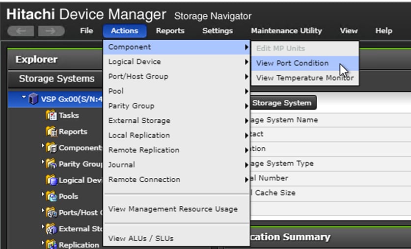
The Port Condition window opens.
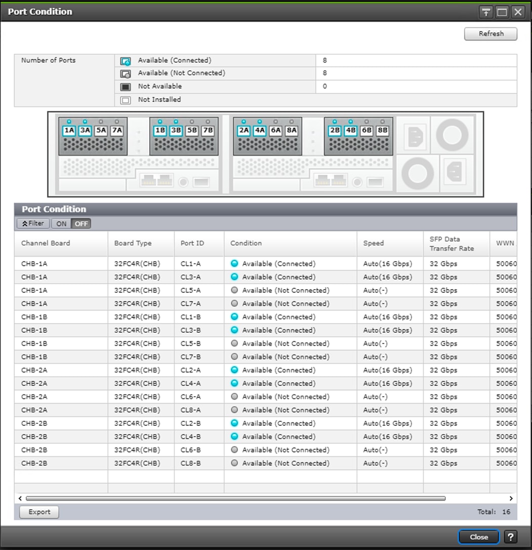
2. Make sure the transfer rate in the SFP Data Transfer Rate matches the speed of the SFPs in the storage controller. The actual Speed can differ, depending on the configuration of the other components.
3. Click Close to close the Port Condition window and start with the storage configuration.
Create Pool Volumes
This procedure creates the Parity Groups and LDEVs using Hitachi Storage Navigator for the following:
· Operating System LUNs
· SAP HANA Shared LUNs
· SAP HANA Log LUNs
· SAP HANA Data LUNs
Use the storage navigator session from the previous section. Repeat these steps to create all the required pool volumes.
To create a pool volume, follow these steps:
1. Open the LDEV creation window.
2. In the General Tasks pane, click Create LDEVs. The 1 Create LDEVs dialog box opens.
3. Create Pool Volume LUN:
a. Create an LDEV.
b. Enter the values shown in Table 13 into the Create LDEVs dialog box.
Table 13 Pool Volume Creation for LOG_Pool and OS_SH_DT_Pool
| For This |
Enter This |
| Provisioning Type |
Click Basic |
| Drive Type/RPM |
Click SSD |
| RAID Level |
Click 1 (2D+2P) |
| Select Free Spaces |
Click the option |
| Parity Group |
Select the 1 (2D+2P) Parity Group |
| LDEV Capacity |
Type value 878 GB |
| Number of LDEVs per Free Space |
Type 4 for each RAID group |
| LDEV Name area |
Type the pool name as prefix and the next free number as int number, i.e. 1 for the first RAID group, 5 for the second etc. |
| Options area |
In the LDKC:CU:DEV text box, type the initial as shown in the LDEV ID column of Table 12 |
| In the MPU assignment text box, select Auto |
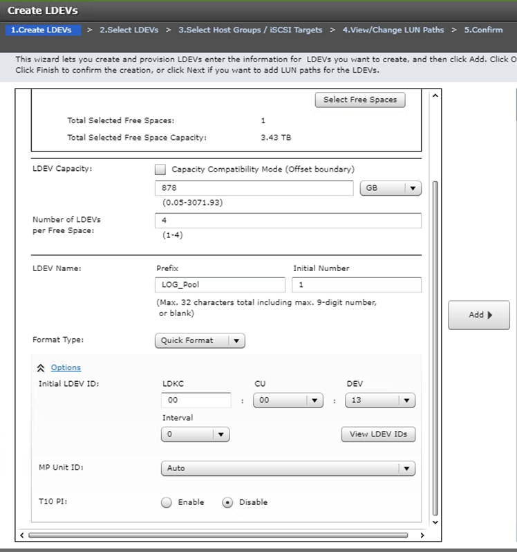
4. Click Add and then click Finish.
5. Acknowledge the Warning by clicking OK.
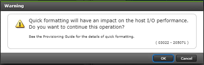
The Confirm window opens.
6. Confirm the selection again, and then click Apply.
7. Record the task name for later reference.
8. Repeat steps 1-7 to create every pool volume required by this installation.
9. Keep the Storage Navigator session open to Create Dynamic Provisioning Pools.
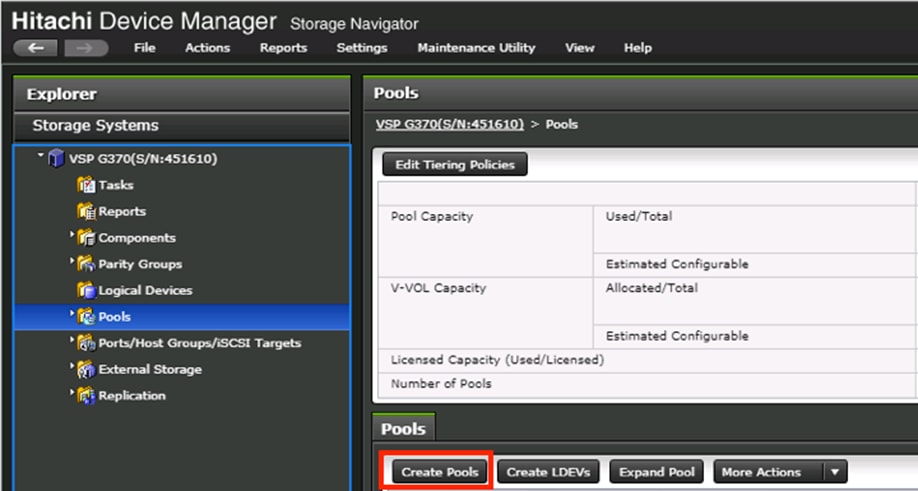
Create Dynamic Provisioning Pools
Use the Storage Navigator session from previous procedure to perform this procedure to create dynamic provisioning pools. This solution uses two dynamic provisioning pools:
· LOG_Pool
· OS_SH_DT_Pool
Follow the steps in this section to create the LOG_Pool and repeat these steps to create the OS_SH_DT_Pool.
To create a dynamic provisioning pool, follow these steps:
1. From Pools, click Create Pools to open the 1. Create Pools window.
2. Enter the values shown in Table 6 in the Create Pools dialog box.
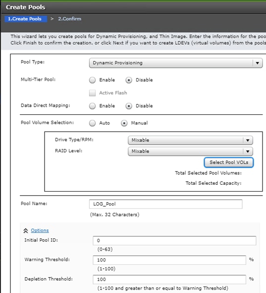
Table 14 Dynamic Provisioning Pool Creation: LOG_Pool and OS_SH_DT_Pool
| For This |
Enter This |
| Pool Type |
Select Dynamic Provisioning |
| Multi-Tier Pool |
Disabled |
| Data Direct Mapping |
Disabled |
| Pool Volume Selection |
Click Manual |
| Pool Name |
LOG_Pool or OS_SH_DT_Pool |
| Initial Pool ID |
Type 0 for LOG_Pool or type 1 for OS_SH_DT_Pool |
| Warning Threshold |
100 |
| Deletion Threshold |
100 |
3. Select the pool volumes for the pool.
4. Click Select Pool VOLs.
5. Select the volumes.
- For LOG_Pool, identify the pool volumes for the pool and select them. Click Add.
- For OS_SH_DT_Pool, identify the pool volumes for the pool and select them. Click Add.
6. Click OK.
7. Click Add.
8. Click Finish on the 2. Confirm window.
9. Click Apply.
Provision the LUNS (Virtual Volumes)
![]() Follow the storage configuration outlined below for this solution. Do not make any changes to these instructions in the Distribution Center. SAP does not support any changes made to this exact configuration.
Follow the storage configuration outlined below for this solution. Do not make any changes to these instructions in the Distribution Center. SAP does not support any changes made to this exact configuration.
This procedure creates the LDEVs using Hitachi Storage Navigator for the following:
· Operating system LUNS
· SAP HANA shared LUNS
· Log LUNs
· Data LUNs
Assign each of the LUNs to specific MPU for optimal performance, map to LUN paths using specific LUN ID in sequence as listed Table 12
Create Virtual Volumes for the Operating System LUNS and Map Ports
Use Hitachi Storage Navigator to create the operating system LDEV and map it to specified Hitachi Virtual Storage Platform Fx00 or Gx00 ports.
To create LDEVs for the operating system boot LUN, follow these steps:
1. From Pools, click OS_SH_DT_Pool.
2. In the Virtual Volumes pane, click Create LDEVs. The 1 Create LDEVs dialog box opens.
3. Create operating system boot LUNS.
4. Create one operating system LUN per HANA node and assign it to the ports following Table 11 . Repeat this step until all operating LUNS are completed.
5. Create an LDEV.
6. Enter the values shown in Table 15 in the Create LDEVs dialog box.
Table 15 LDEV Creation Values for Operating System LUN
| For This |
Enter This |
| Provisioning Type |
Click Dynamic Provisioning |
| Drive Type/RPM |
Click SSD/- |
| RAID Level |
Click 1 (2D+2P) |
| Select Pool |
OS_SH_DT_Pool |
| LDEV Capacity |
Type 100 GB |
| Number of LDEVs per Free Space |
Type the node number to be added to the name. |
| LDEV Name area |
Type the Prefix for the LUN name: HANA_OS_N |
| Type the node number to be added to the name. |
|
| Full Allocation |
Enabled |
| Options area |
Type or click the values for LDKC, CU and DEV according to the VVOL ID column of Table 3 . |
| Select the value Auto for the MPU Unit ID. |
7. Click Add and then click Next.
The 2 Select LDEV window displays all configured LDEVs in the right pane.
8. Select the host ports.
9. Click Next on the 2 Select LDEVs window. The 3 Select Host Groups/iSCSI Targets window opens.
10. From the Available Host Groups pane, select the OS LUN ports by referring to Table 11
11. Click Add.
12. The selected ports that were in the Available Hosts Groups pane are now in the Selected Host Groups pane.
13. Click Next.
14. The 4 View/Change LUN Paths window displays.
15. Confirm the selected ports.
![]() The operating system LUN always has a LUN ID of 000.
The operating system LUN always has a LUN ID of 000.
16. Confirm the selected ports and adjust the LUN ID as listed in Table 4
17. Click Finish.
The 5 Confirm window opens.
18. Confirm the selection again and then click Apply.
19. Record the task name for later reference
20. Keep the Storage Navigator session open for Create Virtual Volumes for HANA Shared File System and Map Ports.
Create Virtual Volumes for HANA Shared File System and Map Ports
Use Hitachi Storage Navigator to create the HANA shared virtual volumes under dynamic provisioning pool OS_SH_DT_Pool and then map them to specified storage ports.
Repeat this procedure until you create all of the virtual volumes.
To create a virtual volume for the HANA-shared file system and map ports, follow these steps:
1. From Pools, click OS_SH_DT_Pool.
2. Enter the values shown in Table 16 in the Create LDEVs dialog box.
Table 16 Virtual Volume Creation for HANA Shared LUNs
| For This |
Enter This |
| Provisioning Type |
Click Dynamic Provisioning |
| Drive Type/RPM |
Leave at SSD/- |
| RAID Level |
Leave at 1 (2D+2P) |
| Select Pool |
OS_SH_DT_Pool |
| LDEV Capacity |
Type the required volume size for /hana/shared volume in GB. This is equal or greater the memory size of the HANA node. |
| Number of LDEVs |
Type 1 |
| Full Allocation |
Click Enabled |
| LDEV Name area |
For LDEV Name Prefix, type the HANA Shared LUN LDEV name: HANA_SH_N |
| Type the node number to be added to the name. |
|
| Options area |
Type or click the values for LDK:CU:DEV according to the VVOL ID column of Table 3 |
| Click Auto for MP Unit ID of the MPU assignment. |
3. Keep the Storage Navigator session open for Create Virtual Volumes for Log LUNs and Map Ports.
Create Virtual Volumes for Log LUNs and Map Ports
This procedure creates and maps LDEVs to the specified storage ports for the log LUNs.
Use the Hitachi Storage Navigator session previously started.
To provision the LDEVs for log LUNs, follow the steps from the previous section with the following changes:
1. From Pools, click LOG_Pool.
2. Enter the values shown in Table 17 in the Create LDEVs dialog box.
Table 17 LDEV Creation Values for Log LUN
| For This |
Enter This |
| Provisioning Type |
Click Dynamic Provisioning |
| Drive Type/RPM |
Click SSD/- |
| RAID Level |
Click 1 (2D+2P) |
| Select Pool |
LOG_Pool |
| LDEV Capacity |
Type the required volume size divided by 4 in GB. For example, if a 512 GB log volume is needed, type 128 GB |
| Number of LDEVs per Free Space |
Type 4 |
| Full Allocation |
Click Enabled |
| LDEV Name area |
For LDEV Name Prefix, type the HANA Log LDEV name for this node: For example: HANA_LOG_N1_ |
| For Initial Number, type the HANA Log LDEV. |
|
| Options area |
Type or click the values for LDKC, CU and DEV in LDKC:CU:DEV according to the VVOL ID column of Table 3 |
| Click the value for the MPU Unit ID. |
3. Keep the Storage Navigator session open for Create Virtual Volumes for Data LUNs and Map Ports.
Create Virtual Volumes for Data LUNs and Map Ports
This procedure creates and maps LDEVs to the specified Hitachi Virtual Storage Platform F370/G370 ports for the Data LUNs.
Use the previously-opened Hitachi Storage Navigator session.
To provision the LDEVs for Data LUNs, follow the steps of the previous sections.
To create virtual volumes for data LUNs and map ports, follow these steps:
1. From Pools, click OS_SH_DT_Pool.
2. Enter the values shown in Table 10 in the Create LDEVs dialog box.
Table 18 LDEV Creation Values for Data LUN
| For This |
Enter This |
| Provisioning Type |
Click Dynamic Provisioning |
| Drive Type/RPM |
Click SSD/- |
| RAID Level |
Click 1 (2D+2P) |
| Select Pool |
OS_SH_DT_Pool |
| LDEV Capacity |
Type the required volume size divided by 4 in GB. For example, if a 4096 GB data volume is needed, type 1024 GB. |
| Number of LDEVs per Free Space |
Type 4 |
| Full Allocation |
Enabled |
| LDEV Name area |
For LDEV Name Prefix, type the HANA Data LDEV name: HANA_DT_VVOL_N |
| For Initial Number, type the HANA node number. |
|
| Options area |
Type or click the values for LDKC, CU and DEV in LDKC:CU:DEV according to the VVOL ID column of Table 11 . |
| Click the value for the MPU Unit ID. |
3. Keep the Storage Navigator session open for the Configure the Host Groups procedure.
Storage Port Configuration
The following table lists the configuration and port mapping for Hitachi VSP Fx00 and Gx00 models.
Table 19 Storage Port Mapping for Validated SAP HANA Nodes using SSDs
| HBA Port |
Fiber Channel Switch Port Name |
Virtual Storage Platform Target Port-Host Group |
|||||||
| Port Name |
Port Speed |
Host |
Storage |
VSP F/G370 |
VSP F/G700 |
VSP F/G900 |
Port Speed |
Port Security |
|
| Node1 |
Port 0 |
16 Gb/s |
SW-1-P0 |
SW-1-P32 |
1A-Host Group 1 |
32 Gb/s |
Enabled |
||
| Port 1 |
16 Gb/s |
SW-2-P0 |
SW-2-P32 |
2A-Host Group 1 |
32 Gb/s |
Enabled |
|||
| Node2 |
Port 0 |
16 Gb/s |
SW-1-P1 |
SW-1-P32 |
1A-Host Group 2 |
32 Gb/s |
Enabled |
||
| Port 1 |
16 Gb/s |
SW-2-P1 |
SW-2-P32 |
2A-Host Group 2 |
32 Gb/s |
Enabled |
|||
| Node3 |
Port 0 |
16 Gb/s |
SW-1-P2 |
SW-1-P33 |
3A-Host Group 1 |
32 Gb/s |
Enabled |
||
| Port 1 |
16 Gb/s |
SW-2-P2 |
SW-2-P33 |
4A-Host Group 1 |
32 Gb/s |
Enabled |
|||
| Node4 |
Port 0 |
16 Gb/s |
SW-1-P3 |
SW-1-P33 |
3A-Host Group 2 |
32 Gb/s |
Enabled |
||
| Port 1 |
16 Gb/s |
SW-2-P3 |
SW-2-P33 |
4A-Host Group 2 |
32 Gb/s |
Enabled |
|||
| Node5 |
Port 0 |
16 Gb/s |
SW-1-P4 |
SW-1-P34 |
5A-Host Group 1 |
32 Gb/s |
Enabled |
||
| Port 1 |
16 Gb/s |
SW-2-P4 |
SW-2-P34 |
6A-Host Group 1 |
32 Gb/s |
Enabled |
|||
| Node6 |
Port 0 |
16 Gb/s |
SW-1-P5 |
SW-1-P34 |
5A-Host Group 2 |
32 Gb/s |
Enabled |
||
| Port 1 |
16 Gb/s |
SW-2-P5 |
SW-2-P34 |
6A-Host Group 2 |
32 Gb/s |
Enabled |
|||
| Node7 |
Port 0 |
16 Gb/s |
SW-1-P6 |
SW-1-P35 |
7A-Host Group 1 |
32 Gb/s |
Enabled |
||
| Port 1 |
16 Gb/s |
SW-2-P6 |
SW-2-P35 |
8A-Host Group 1 |
32 Gb/s |
Enabled |
|||
| Node8 |
Port 0 |
16 Gb/s |
SW-1-P7 |
SW-1-P35 |
7A-Host Group 2 |
32 Gb/s |
Enabled |
||
| Port 1 |
16 Gb/s |
SW-2-P7 |
SW-2-P35 |
8A-Host Group 2 |
32 Gb/s |
Enabled |
|||
| Node9 |
Port 0 |
16 Gb/s |
SW-1-P8 |
SW-1-P36 |
1B-Host Group 1 |
32 Gb/s |
Enabled |
||
| Port 1 |
16 Gb/s |
SW-2-P8 |
SW-2-P36 |
2B-Host Group 1 |
32 Gb/s |
Enabled |
|||
| Node10 |
Port 0 |
16 Gb/s |
SW-1-P9 |
SW-1-P36 |
1B-Host Group 2 |
32 Gb/s |
Enabled |
||
| Port 1 |
16 Gb/s |
SW-2-P9 |
SW-2-P36 |
2B-Host Group 2 |
32 Gb/s |
Enabled |
|||
| Node11 |
Port 0 |
16 Gb/s |
SW-1-P10 |
SW-1-P37 |
3B-Host Group 1 |
32 Gb/s |
Enabled |
||
| Port 1 |
16 Gb/s |
SW-2-P10 |
SW-2-P37 |
4B-Host Group 1 |
32 Gb/s |
Enabled |
|||
| Node12 |
Port 0 |
16 Gb/s |
SW-1-P11 |
SW-1-P37 |
3B-Host Group 2 |
32 Gb/s |
Enabled |
||
| Port 1 |
16 Gb/s |
SW-2-P11 |
SW-2-P37 |
4B-Host Group 2 |
32 Gb/s |
Enabled |
|||
| Node13 |
Port 0 |
16 Gb/s |
SW-1-P12 |
SW-1-P38 |
5B-Host Group 1 |
32 Gb/s |
Enabled |
||
| Port 1 |
16 Gb/s |
SW-2-P12 |
SW-2-P38 |
6B-Host Group 1 |
32 Gb/s |
Enabled |
|||
| Node14 |
Port 0 |
16 Gb/s |
SW-1-P13 |
SW-1-P38 |
5B-Host Group 2 |
32 Gb/s |
Enabled |
||
| Port 1 |
16 Gb/s |
SW-2-P13 |
SW-2-P38 |
6B-Host Group 2 |
32 Gb/s |
Enabled |
|||
| Node15 |
Port 0 |
16 Gb/s |
SW-1-P14 |
SW-1-P39 |
7B-Host Group 1 |
32 Gb/s |
Enabled |
||
| Port 1 |
16 Gb/s |
SW-2-P14 |
SW-2-P39 |
8B-Host Group 1 |
32 Gb/s |
Enabled |
|||
| Node16 |
Port 0 |
16 Gb/s |
SW-1-P15 |
SW-1-P39 |
7B-Host Group 2 |
32 Gb/s |
Enabled |
||
| Port 1 |
16 Gb/s |
SW-2-P15 |
SW-2-P39 |
8B-Host Group 2 |
32 Gb/s |
Enabled |
|||
| Node17 |
Port 0 |
16 Gb/s |
SW-1-P16 |
SW-1-P40 |
N/A |
1C-Host Group 1 |
32 Gb/s |
Enabled |
|
| Port 1 |
16 Gb/s |
SW-2-P16 |
SW-2-P40 |
N/A |
2C-Host Group 1 |
32 Gb/s |
Enabled |
||
| Node18 |
Port 0 |
16 Gb/s |
SW-1-P17 |
SW-1-P40 |
N/A |
1C-Host Group 2 |
32 Gb/s |
Enabled |
|
| Port 1 |
16 Gb/s |
SW-2-P17 |
SW-2-P40 |
N/A |
2C-Host Group 2 |
32 Gb/s |
Enabled |
||
| Node19 |
Port 0 |
16 Gb/s |
SW-1-P18 |
SW-1-P41 |
N/A |
3C-Host Group 1 |
32 Gb/s |
Enabled |
|
| Port 1 |
16 Gb/s |
SW-2-P18 |
SW-2-P41 |
N/A |
4C-Host Group 1 |
32 Gb/s |
Enabled |
||
| Node20 |
Port 0 |
16 Gb/s |
SW-1-P19 |
SW-1-P41 |
N/A |
3C-Host Group 2 |
32 Gb/s |
Enabled |
|
| Port 1 |
16 Gb/s |
SW-2-P19 |
SW-2-P41 |
N/A |
4C-Host Group 2 |
32 Gb/s |
Enabled |
||
| Node21 |
Port 0 |
16 Gb/s |
SW-1-P20 |
SW-1-P42 |
N/A |
5C-Host Group 1 |
32 Gb/s |
Enabled |
|
| Port 1 |
16 Gb/s |
SW-2-P20 |
SW-2-P42 |
N/A |
6C-Host Group 1 |
32 Gb/s |
Enabled |
||
| Node22 |
Port 0 |
16 Gb/s |
SW-1-P21 |
SW-1-P42 |
N/A |
5C-Host Group 2 |
32 Gb/s |
Enabled |
|
| Port 1 |
16 Gb/s |
SW-2-P21 |
SW-2-P42 |
N/A |
6C-Host Group 2 |
32 Gb/s |
Enabled |
||
| Node23 |
Port 0 |
16 Gb/s |
SW-1-P22 |
SW-1-P43 |
N/A |
7C-Host Group 1 |
32 Gb/s |
Enabled |
|
| Port 1 |
16 Gb/s |
SW-2-P22 |
SW-2-P43 |
N/A |
8C-Host Group 1 |
32 Gb/s |
Enabled |
||
| Node24 |
Port 0 |
16 Gb/s |
SW-1-P23 |
SW-1-P43 |
N/A |
7C-Host Group 2 |
32 Gb/s |
Enabled |
|
| Port 1 |
16 Gb/s |
SW-2-P23 |
SW-2-P43 |
N/A |
8C-Host Group 2 |
32 Gb/s |
Enabled |
||
| Node25 |
Port 0 |
16 Gb/s |
SW-1-P24 |
SW-1-P44 |
N/A |
1D-Host Group 1 |
32 Gb/s |
Enabled |
|
| Port 1 |
16 Gb/s |
SW-2-P24 |
SW-2-P44 |
N/A |
2D-Host Group 1 |
32 Gb/s |
Enabled |
||
| Node26 |
Port 0 |
16 Gb/s |
SW-1-P25 |
SW-1-P44 |
N/A |
1D-Host Group 2 |
32 Gb/s |
Enabled |
|
| Port 1 |
16 Gb/s |
SW-2-P25 |
SW-2-P44 |
N/A |
2D-Host Group 2 |
32 Gb/s |
Enabled |
||
| Node27 |
Port 0 |
16 Gb/s |
SW-1-P26 |
SW-1-P45 |
N/A |
3D-Host Group 1 |
32 Gb/s |
Enabled |
|
| Port 1 |
16 Gb/s |
SW-2-P26 |
SW-2-P45 |
N/A |
4D-Host Group 1 |
32 Gb/s |
Enabled |
||
| Node28 |
Port 0 |
16 Gb/s |
SW-1-P27 |
SW-1-P45 |
N/A |
3D-Host Group 2 |
32 Gb/s |
Enabled |
|
| Port 1 |
16 Gb/s |
SW-2-P27 |
SW-2-P45 |
N/A |
4D-Host Group 2 |
32 Gb/s |
Enabled |
||
| Node29 |
Port 0 |
16 Gb/s |
SW-1-P28 |
SW-1-P46 |
N/A |
5D-Host Group 1 |
32 Gb/s |
Enabled |
|
| Port 1 |
16 Gb/s |
SW-2-P28 |
SW-2-P46 |
N/A |
6D-Host Group 1 |
32 Gb/s |
Enabled |
||
| Node30 |
Port 0 |
16 Gb/s |
SW-1-P29 |
SW-1-P46 |
N/A |
5D-Host Group 2 |
32 Gb/s |
Enabled |
|
| Port 1 |
16 Gb/s |
SW-2-P29 |
SW-2-P46 |
N/A |
6D-Host Group 2 |
32 Gb/s |
Enabled |
||
| Node31 |
Port 0 |
16 Gb/s |
SW-1-P30 |
SW-1-P47 |
N/A |
7D-Host Group 1 |
32 Gb/s |
Enabled |
|
| Port 1 |
16 Gb/s |
SW-2-P30 |
SW-2-P47 |
N/A |
8D-Host Group 1 |
32 Gb/s |
Enabled |
||
| Node32 |
Port 0 |
16 Gb/s |
SW-1-P31 |
SW-1-P47 |
N/A |
7D-Host Group 2 |
32 Gb/s |
Enabled |
|
| Port 1 |
16 Gb/s |
SW-2-P31 |
SW-2-P47 |
N/A |
8D-Host Group 2 |
32 Gb/s |
Enabled |
||
Configure the Host Groups
To configure the host ports, follow these steps:
1. Open the Ports/Host Group/iSCSI Targets window.
2. In Storage Systems under the Explorer pane, expand the VSP Gx00 tree.
3. Click Ports/Host Groups/iSCSI Targets.
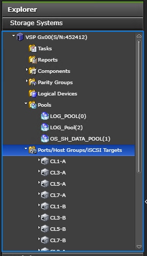
4. In the right pane of the Ports/Host Groups/iSCSI Targets window, click the Ports tab to see the list of ports.
5. Select all required ports and click Edit Ports.
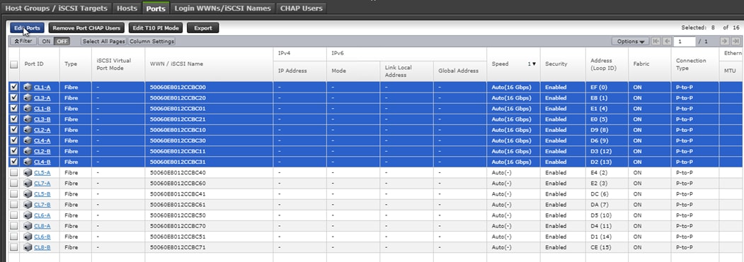
6. Enter the properties in the Edit Ports window, see Table 12
| For This |
Enter This |
| Port Security |
Select the check box and click the Enabled option. |
| Port Speed |
Select the check box and click the speed matching your connection speed. For example, select 32 Gbps. |
| Fabric |
Select the check box and click ON. |
| Connection Type |
Select the check box and click P-to-P. |
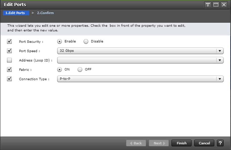
This section describes the specific configurations on Cisco UCS servers to address the SAP HANA requirements.
It is beyond the scope of this document to cover detailed information about the Cisco UCS infrastructure. Detailed configuration guides are at: https://www.cisco.com/c/en/us/support/servers-unified-computing/ucs-manager/products-installation-and-configuration-guides-list.html
Physical Connectivity
Physical cabling should be completed by following the diagram and table references in section Deployment Hardware and Software.
Upgrade Cisco UCS Manager Software to Version 4.0(1c)
This document based on Cisco UCS 4.0(1c). To upgrade the Cisco UCS Manager software and the Cisco UCS Fabric Interconnect software to version 4.0(1c), go to Cisco UCS Manager Install and Upgrade Guides.
Initial Setup of Cisco UCS 6332-16UP Fabric Interconnects
The initial configuration dialogue for the Cisco UCS 6332-16UP Fabric Interconnects will be provide the primary information to the first fabric interconnect, with the second taking on most settings after joining the cluster.
To start on the configuration of the Fabric Interconnect A, connect to the console of the fabric interconnect and step through the Basic System Configuration Dialogue:
---- Basic System Configuration Dialog ----
This setup utility will guide you through the basic configuration of
the system. Only minimal configuration including IP connectivity to
the Fabric interconnect and its clustering mode is performed through these steps.
Type Ctrl-C at any time to abort configuration and reboot system.
To back track or make modifications to already entered values,
complete input till end of section and answer no when prompted
to apply configuration.
Enter the configuration method. (console/gui) ? console
Enter the setup mode; setup newly or restore from backup. (setup/restore) ? setup
You have chosen to setup a new Fabric interconnect. Continue? (y/n): y
Enforce strong password? (y/n) [y]: <enter>
Enter the password for "admin": <<var_password>>
Confirm the password for "admin": <<var_password>>
Is this Fabric interconnect part of a cluster(select 'no' for standalone)? (yes/no) [n]: yes
Enter the switch fabric (A/B) []: A
Enter the system name: <<var_ucs_clustername>>
Physical Switch Mgmt0 IP address : <<var_ucsa_mgmt_ip>>
Physical Switch Mgmt0 IPv4 netmask : <<var_oob_mgmt_mast>>
IPv4 address of the default gateway : <<var_oob_gateway>>
Cluster IPv4 address : <<var_ucs_mgmt_ip>>
Configure the DNS Server IP address? (yes/no) [n]: y
DNS IP address : <<var_nameserver_ip>>
Configure the default domain name? (yes/no) [n]: y
Default domain name : <<var_dns_domain_name>>
Join centralized management environment (UCS Central)? (yes/no) [n]: <enter>
Following configurations will be applied:
Switch Fabric=A
System Name=<<var_ucs_clustername>>
Enforced Strong Password=yes
Physical Switch Mgmt0 IP Address=<<var_ucsa_mgmt_ip>>
Physical Switch Mgmt0 IP Netmask=<<var_oob_mgmt_mast>>
Default Gateway=<<var_oob_gateway>>
Ipv6 value=0
DNS Server=<<var_nameserver_ip>>
Domain Name=<<var_dns_domain_name>>
Cluster Enabled=yes
Cluster IP Address=<<var_ucs_mgmt_ip>>
NOTE: Cluster IP will be configured only after both Fabric Interconnects are initialized.
UCSM will be functional only after peer FI is configured in clustering mode.
Apply and save the configuration (select 'no' if you want to re-enter)? (yes/no):yes
Wait for the login prompt to make sure that the configuration has been saved.
Cisco UCS 6332-16UP Fabric Interconnect B
Continue the configuration on the console of the Fabric Interconnect B:
---- Basic System Configuration Dialog ----
This setup utility will guide you through the basic configuration of
the system. Only minimal configuration including IP connectivity to
the Fabric interconnect and its clustering mode is performed through these steps.
Type Ctrl-C at any time to abort configuration and reboot system.
To back track or make modifications to already entered values,
complete input till end of section and answer no when prompted
to apply configuration.
Enter the configuration method. (console/gui) ? console
Installer has detected the presence of a peer Fabric interconnect. This Fabric interconnect will be added to the cluster. Continue (y/n) ? y
Enter the admin password of the peer Fabric interconnect:
Connecting to peer Fabric interconnect... done
Retrieving config from peer Fabric interconnect... done
Peer Fabric interconnect Mgmt0 IPv4 Address: <<var_ucsa_mgmt_ip>>
Peer Fabric interconnect Mgmt0 IPv4 Netmask: <<var_oob_mgmt_mast>>
Cluster IPv4 address : <<var_ucs_mgmt_ip>>
Peer FI is IPv4 Cluster enabled. Please Provide Local Fabric Interconnect Mgmt0 IPv4 Address
Physical Switch Mgmt0 IP address : <<var_ucsb_mgmt_ip>>
Apply and save the configuration (select 'no' if you want to re-enter)? (yes/no):yes
Wait for the login prompt to make sure that the configuration has been saved.
Cisco UCS Manager Setup
Log into Cisco UCS Manager
To log into the Cisco Unified Computing System environment, follow these steps:
1. Open a web browser and navigate to the Cisco UCS 6332 Fabric Interconnect cluster IP address.
Figure 3 Accessing Cisco UCS Manager
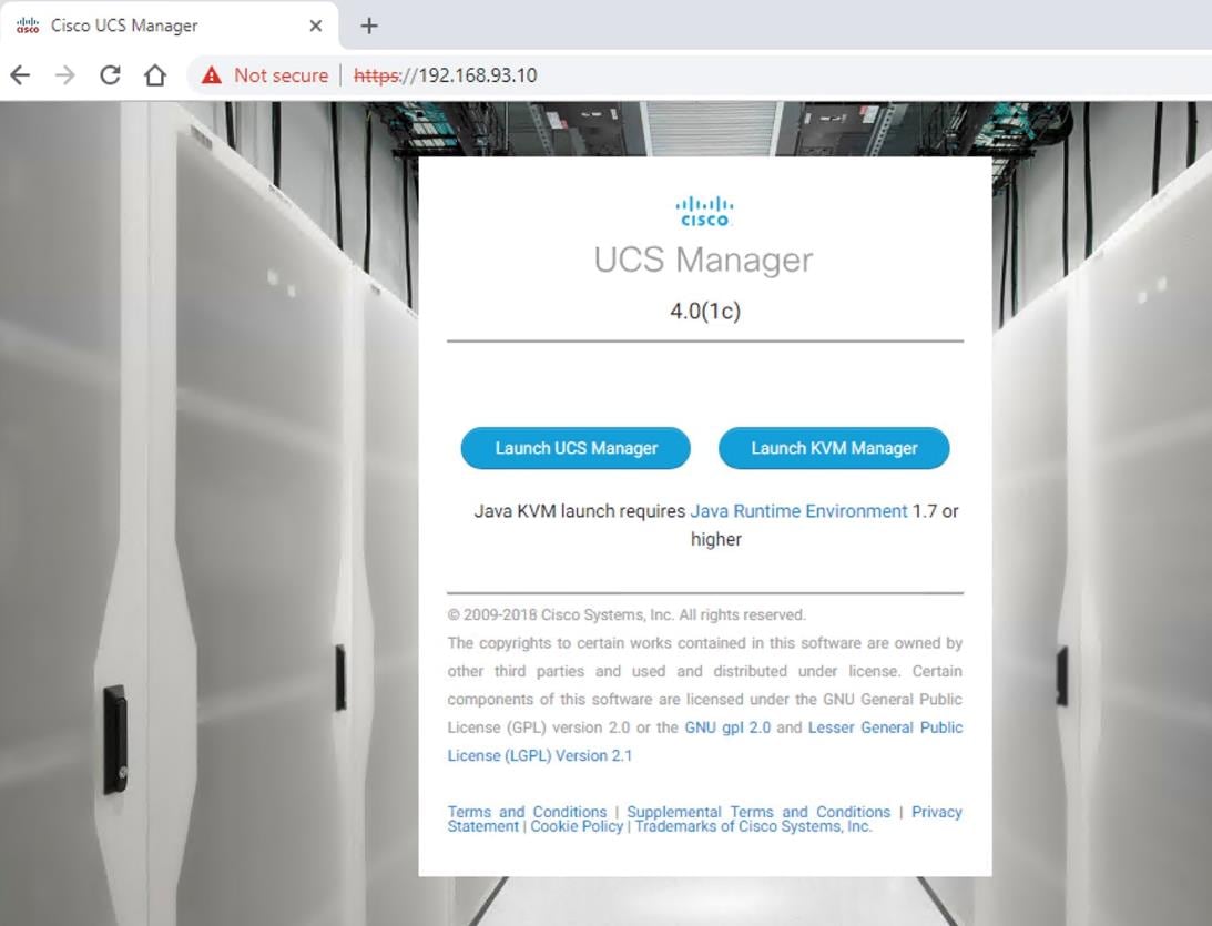
2. Click Launch UCS Manager.
3. If prompted to accept security certificates, accept as necessary.
4. When prompted, enter admin as the user name and enter the administrative password.
5. Click Login to log into the Cisco UCS Manager.
Figure 4 Cisco UCS Manager Page
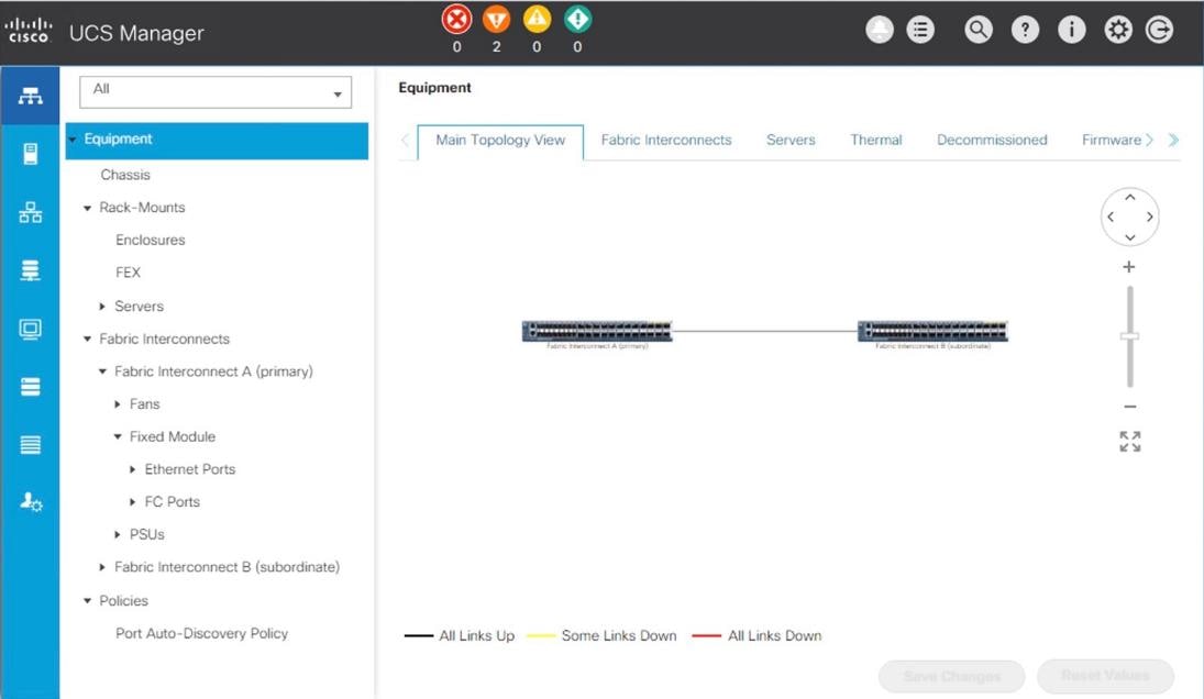
Anonymous Reporting
During the first connection to the Cisco UCS Manager GUI, a pop-up window will appear to allow for the configuration of Anonymous Reporting to Cisco on use to help with future development. To create anonymous reporting, complete the following step:
1. In the Anonymous Reporting window, select whether to send anonymous data to Cisco for improving future products, and provide the appropriate SMTP server gateway information if configuring:
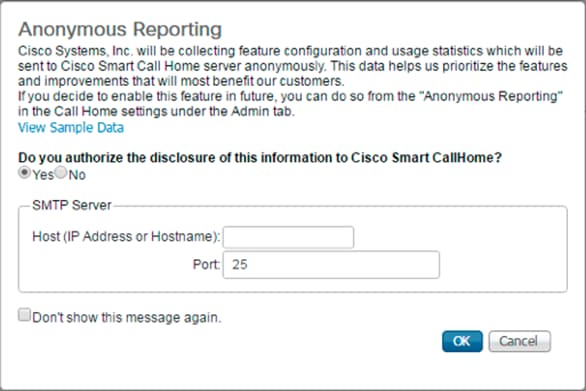
If you want to enable or disable Anonymous Reporting at a later date, it can be found within Cisco UCS Manager under: Admin -> Communication Management -> Call Home, which has a tab on the far right for Anonymous Reporting.
Synchronize Cisco UCS to NTP
To synchronize the Cisco UCS environment to the NTP server, follow these steps:
1. In Cisco UCS Manager, click the Admin tab in the navigation pane.
2. Select Timezone Management drop-down list and click Timezone.
3. In the Properties pane, select the appropriate time zone in the Timezone menu.
4. Click Save Changes, and then click OK.
5. Click Add NTP Server.
6. Enter <<var_oob_ntp>> and click OK.
Configure Cisco UCS Servers
Chassis Discovery Policy
Setting the discovery policy simplifies the addition of B-Series Cisco UCS chassis. To modify the chassis discovery policy, follow these steps:
1. In Cisco UCS Manager, click the Equipment tab in the navigation pane and select Equipment in the list on the left.
2. In the right pane, click the Policies tab.
3. Under Global Policies, set the Chassis/FEX Discovery Policy to match the number of uplink ports that are cabled between the chassis or fabric extenders (FEXes) and the fabric interconnects. Set the Link Grouping Preference to Port Channel.
4. Click Save Changes.
5. Click OK.
Figure 5 Chassis/FEX and Rack Server Discovery Policy
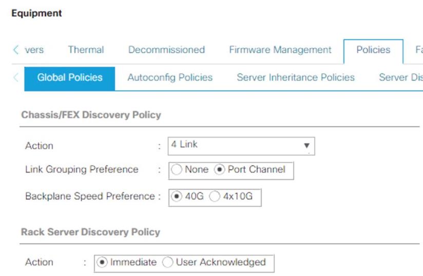
Configure Server Ports
To enable server and uplink ports, follow these steps:
1. In Cisco UCS Manager, click the Equipment tab in the navigation pane.
2. Select Equipment > Fabric Interconnects > Fabric Interconnect A (primary) > Fixed Module.
3. Click Ethernet Ports.
4. On the main pane, select the ports that are connected to the chassis and / or to the Cisco C-Series Server (two per FI), right-click them, and select Configure as Server Port.
5. Click Yes to confirm server ports and click OK.
6. Verify that the ports connected to the chassis and / or to the Cisco C-Series Server are now configured as server ports.
Figure 6 Cisco UCS – Server Port Configuration Example
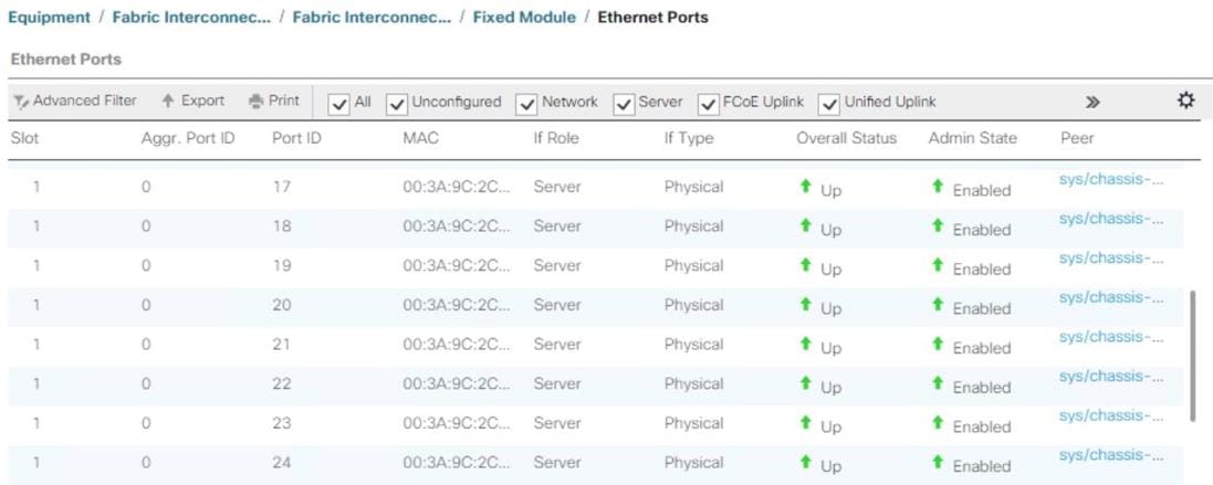
7. Select Equipment > Fabric Interconnects > Fabric Interconnect B (subordinate) > Fixed Module.
8. Click Ethernet Ports.
9. On the main pane, select the ports that are connected to the chassis or to the Cisco C-Series Server (two per FI), right-click them, and select Configure as Server Port.
10. Click Yes to confirm server ports and click OK.
Configure FC SAN Uplink Ports
To configure the FC SAN Uplink ports, follow these steps:
1. Configure the ports connected to the MDS as FC SAN Uplink Ports. This step creates the first set of ports from the left for example, ports 1-6 of the Fixed Module for FC uplinks and the rest for Ethernet uplinks to N9Ks.
![]() While configuring the Fixed Module Ports, the slider bar movement enables sets of ports from the left of the module as FC ports. The remainder is available for Ethernet Uplinks. This step used 4 ports for uplink to MDS, it would be enough to configure first set of 6 ports as FC ports.
While configuring the Fixed Module Ports, the slider bar movement enables sets of ports from the left of the module as FC ports. The remainder is available for Ethernet Uplinks. This step used 4 ports for uplink to MDS, it would be enough to configure first set of 6 ports as FC ports.
2. Select Equipment > Fabric Interconnects > Fabric Interconnect A and on the right pane, General > Under Actions > Configure Unified Ports. Choose Yes for the warning pop-up In Cisco UCS Manager, click the Equipment tab in the navigation pane. Move the slider bar to right to enable the first set of 6 ports for FC Uplink Role. Click OK.
Figure 7 Cisco UCS – Configure Fixed Module Ports

3. Configuring the unified ports require immediate reboot. Click on Yes on the warning pop-up to reboot the Fabric Interconnect.
4. Select Equipment > Fabric Interconnects > Fabric Interconnect B and on the right pane, General > Under Actions > Configure Unified Ports. Choose Yes for the warning pop-up In Cisco UCS Manager, click the Equipment tab in the navigation pane. Move the slider bar to right to enable the first set of 6 ports for FC Uplink Role. Click OK.
5. Configuring the unified ports require immediate reboot. Click on Yes on the warning pop-up to reboot the Fabric Interconnect.
6. After the FIs are accessible after reboot, re-login to Cisco UCS Manager.
Configure Ethernet Uplink Ports
To configure the ethernet uplink ports, follow these steps:
1. Configure the ports connected to the N9Ks Ethernet Uplink Ports.
![]() Select ports in the range 17-34 for the 40GE Uplink Port connectivity.
Select ports in the range 17-34 for the 40GE Uplink Port connectivity.
2. In Cisco UCS Manager, click the Equipment tab in the navigation pane.
3. Select Equipment > Fabric Interconnects > Fabric Interconnect A (primary) > Fixed Module.
4. Expand Ethernet Ports.
5. Select ports that are connected to the Cisco Nexus switches, right-click them, and select Configure as Uplink Port.
6. Click Yes to confirm uplink ports and click OK.
Figure 8 Cisco UCS – Ethernet Uplink Port FI-A Configuration Example
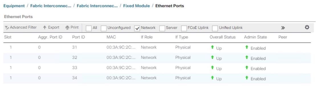
7. Select Equipment > Fabric Interconnects > Fabric Interconnect B (subordinate) > Fixed Module.
8. Expand Ethernet Ports.
9. Select ports that are connected to the Cisco Nexus switches, right-click them, and select Configure as Uplink Port.
10. Click Yes to confirm the uplink ports and click OK.
Acknowledge Cisco UCS Chassis
To acknowledge all Cisco UCS chassis, follow these steps:
1. In Cisco UCS Manager, click the Equipment tab in the navigation pane.
2. Expand Chassis and select each chassis that is listed. Right-click each chassis and select Acknowledge Chassis.
3. After a while, ensure the Discovery completes successfully and there are no major or critical faults reported for any of the servers.
Figure 9 Servers Discovery Status Complete
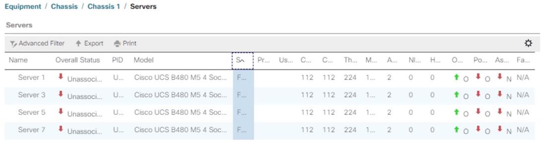
Power Policy
To run Cisco UCS with two independent power distribution units, the redundancy must be configured as Grid. Follow these steps:
1. In Cisco UCS Manager, click the Equipment tab in the navigation pane and select Equipment in the list on the left.
2. In the right pane, click the Policies tab.
3. Under Global Policies, set the Redundancy field in Power Policy to Grid.
4. Click Save Changes.
5. Click OK.
Figure 10 Power Policy
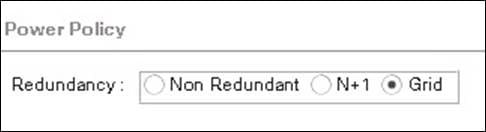
Create New Organization
For secure multi-tenancy within the Cisco UCS domain, a logical entity known as organization is created.
To create an organization unit, follow these steps:
1. In Cisco UCS Manager, on the Tool bar on right pane top click New.
Figure 11 Cisco UCS – Create Organization
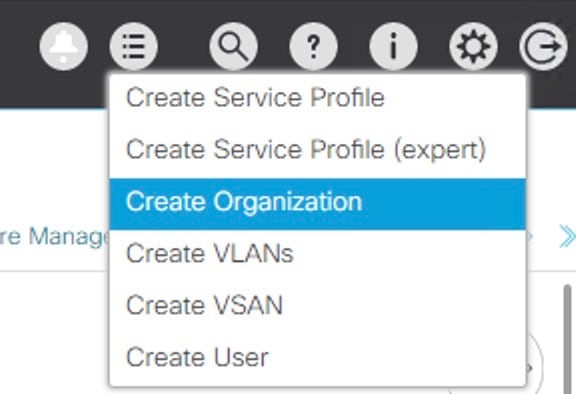
2. From the drop-down menu select Create Organization.
3. Enter the Name as T01-HANA
4. (Optional) Enter the Description as Org for T01-HANA.
5. Click OK to create the Organization.
Create Pools
Add Block of IP Addresses for KVM Access
To create a block of IP addresses for server Keyboard, Video, Mouse (KVM) access in the Cisco UCS environment, follow these steps:
![]() This block of IP addresses should be in the same subnet as the management IP addresses for the Cisco UCS Manager.
This block of IP addresses should be in the same subnet as the management IP addresses for the Cisco UCS Manager.
1. In Cisco UCS Manager, click the LAN tab in the navigation pane.
2. Select Pools > root > IP Pools > IP Pool ext-mgmt.
3. In the Actions pane, select Create Block of IPv4 Addresses.
4. Enter the starting IP address of the block and the number of IP addresses required, and the subnet and gateway information.
Figure 12 Cisco UCS - Create IP Pool
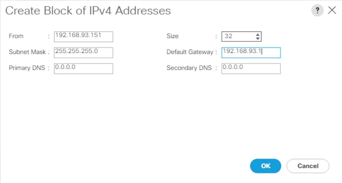
5. Click OK to create the IP block.
6. Click OK in the confirmation message.
Create MAC Address Pools
To configure the necessary MAC address pools for the Cisco UCS environment, follow these steps:
1. In Cisco UCS Manager, click the LAN tab in the navigation pane.
2. Select Pools > root
3. In this procedure, two MAC address pools are created, one for each switching fabric.
4. Right-click MAC Pools under the root
5. Select Create MAC Pool to create the MAC address pool.
6. Enter FI-A as the name of the MAC pool.
7. (Optional) Enter a description for the MAC pool.
8. Choose Assignment Order Sequential.
9. Click Next.
10. Click Add.
11. Specify a starting MAC address.
12. The recommendation is to place 0A in the second-last octet of the starting MAC address to identify all of the MAC addresses as Fabric Interconnect A addresses.
13. Specify a size for the MAC address pool that is sufficient to support the available blade or server resources.
Figure 13 Cisco UCS – Create MAC Pool for Fabric A
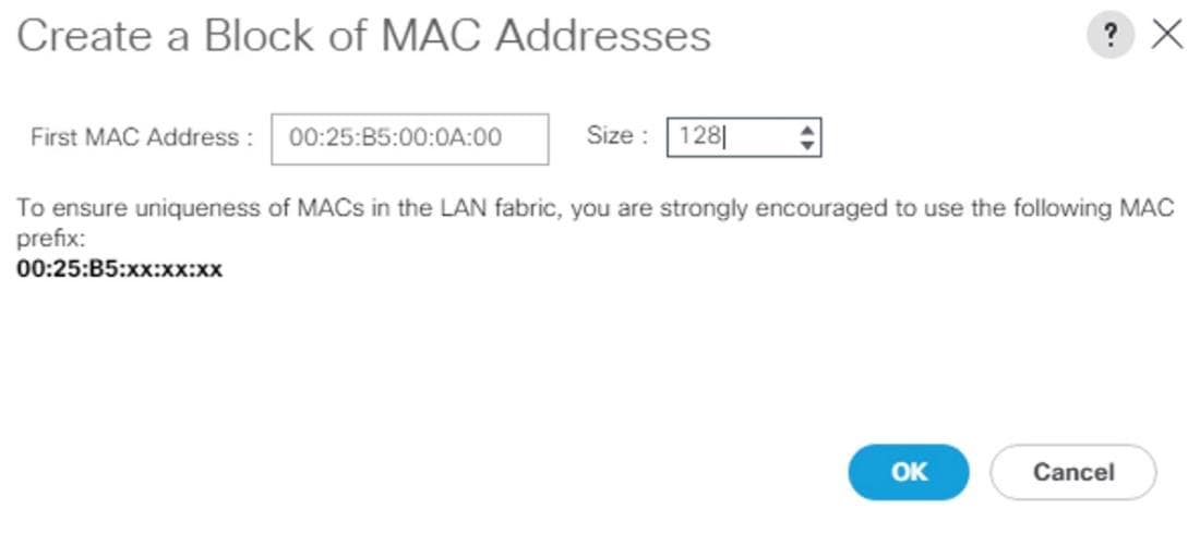
14. Click OK.
15. Click Finish.
16. In the confirmation message, click OK.
17. Right-click MAC Pools under root
18. Select Create MAC Pool to create the MAC address pool.
19. Enter FI-B as the name of the MAC pool.
20. (Optional) Enter a description for the MAC pool. Select ‘Sequential’ for Assignment order.
21. Click Next.
22. Click Add.
23. Specify a starting MAC address.
![]() The recommendation is to place 0B in the next to last octet of the starting MAC address to identify all the MAC addresses in this pool as fabric B addresses.
The recommendation is to place 0B in the next to last octet of the starting MAC address to identify all the MAC addresses in this pool as fabric B addresses.
24. Specify a size for the MAC address pool that is sufficient to support the available blade or server resources.
25. Click OK.
26. Click Finish.
27. In the confirmation message, click OK.
Figure 14 Cisco UCS – MAC Pools Summary
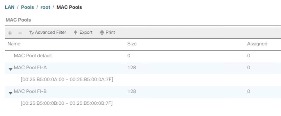
Create WWNN Pool
To configure the necessary WWNN pool for the Cisco UCS environment, follow these steps:
1. In Cisco UCS Manager, click the SAN tab in the navigation pane.
2. Select Pools > root
3. Right-click WWNN Pools and Select Create WWNN Pool.
4. Enter HANA-Servers as the name of the WWNN pool.
5. (Optional) Enter a description for the WWNN pool.
6. Choose Assignment Order Sequential.
7. Click Next.
8. Click Add.
9. Specify a starting WWNN address.
10. The recommendation is to place AB in the third-last octet of the starting WWNN address to ensure uniqueness.
11. Specify a size for the WWNN pool that is sufficient to support the available blade or server resources.
Figure 15 Cisco UCS – Create WWNN Pool
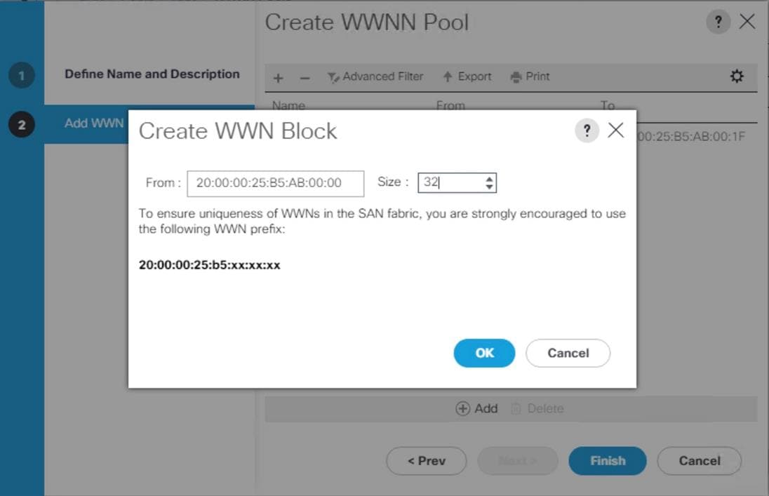
12. Click OK.
13. Click Finish.
14. In the confirmation message, click OK.
Create WWPN Pool
To configure the necessary WWPN pool for the Cisco UCS environment, follow these steps:
1. In Cisco UCS Manager, click the SAN tab in the navigation pane.
2. Select Pools > root
3. In this procedure, two WWPN pools are created, one for each switching fabric.
4. Right-click WWPN Pools and Select Create WWPN Pool
5. Enter FI-A as the name of the WWPN pool.
6. (Optional) Enter a description for the WWPN pool.
7. Choose Assignment Order Sequential.
8. Click Next.
9. Click Add.
10. Specify a starting WWPN address.
11. The recommendation is to place 0A in the last bust one octet of the starting MAC address to identify all of the WWPN addresses as Fabric Interconnect A addresses.
12. Specify a size for the WWPN address pool that is sufficient to support the available blade or server resources.
Figure 16 Cisco UCS – Create WWPN Pool for Fabric A

13. Click OK.
14. Click Finish.
15. In the confirmation message, click OK.
16. Right-click WWPN Pools and Select Create WWPN Pool.
17. Enter FI-B as the name of the WWPN pool.
18. (Optional) Enter a description for the WWPN pool. Select ‘Sequential’ for Assignment order.
19. Click Next.
20. Click Add.
21. Specify a starting WWPN address.
![]() It is recommended to place 0B in the next to third-last octet of the starting WWPN address to identify all the WWPN addresses in this pool as fabric B addresses.
It is recommended to place 0B in the next to third-last octet of the starting WWPN address to identify all the WWPN addresses in this pool as fabric B addresses.
22. Specify a size for the WWPN address pool that is sufficient to support the available blade or server resources.
23. Click OK.
24. Click Finish.
25. In the confirmation message, click OK.
Figure 17 WWPN Pool Summary
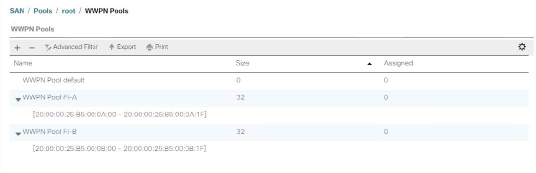
Create UUID Suffix Pool
To configure the necessary universally unique identifier (UUID) suffix pool for the Cisco UCS environment, follow these steps:
1. In Cisco UCS Manager, click the Servers tab in the navigation pane.
2. Select Pools > root
3. Right-click UUID Suffix Pools.
4. Select Create UUID Suffix Pool.
5. Enter HANA-UUID as the name of the UUID suffix pool.
6. (Optional) Enter a description for the UUID suffix pool.
7. Keep the Prefix as the Derived option.
8. Select Sequential for Assignment Order
9. Click Next.
10. Click Add to add a block of UUIDs.
11. Keep the ‘From’ field at the default setting.
12. Specify a size for the UUID block that is sufficient to support the available blade or server resources.
Figure 18 Cisco UCS – Create UUID Block
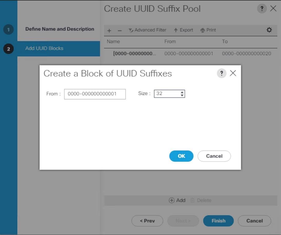
13. Click OK.
14. Click Finish.
15. Click OK.
Set Packages and Policies
Create Host Firmware Package
Firmware management policies allow the administrator to select the corresponding packages for a given server configuration. These policies often include packages for adapter, BIOS, board controller, FC adapters, host bus adapter (HBA) option ROM, and storage controller properties.
To create a firmware management policy for a given server configuration in the Cisco UCS environment, follow these steps:
1. In Cisco UCS Manager, click the Servers tab in the navigation pane.
2. Select Policies > root.
3. Right-click Host Firmware Packages.
4. Select Create Host Firmware Package.
5. Enter HANA-FW as the name of the host firmware package.
6. Leave Simple selected.
7. Select the version 4.0(1c)B for the Blade Package and 4.0(1c)C for Rack Packages.
![]() The Firmware Package Version dependent on UCSM version installed
The Firmware Package Version dependent on UCSM version installed
8. Click OK to create the host firmware package.
9. Click OK.
Figure 19 Host Firmware Package
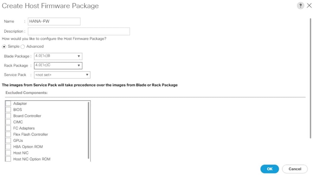
Create Server BIOS Policy
To get best performance for HANA it is required to configure the Server BIOS accurately. To create a server BIOS policy for the Cisco UCS environment, follow these steps:
1. In Cisco UCS Manager, click the Servers tab in the navigation pane.
2. Select Policies > root
3. Right-click BIOS Policies.
4. Select Create BIOS Policy.
5. Enter HANA-BIOS as the BIOS policy name.
6. Select “Reboot on BIOS Settings Change”. Click OK.
7. Select the BIOS policy selected on the navigation pane.
8. On the ‘Main’ sub-heading, change the Quiet Boot setting to Disabled.
Figure 20 Create Server BIOS Policy
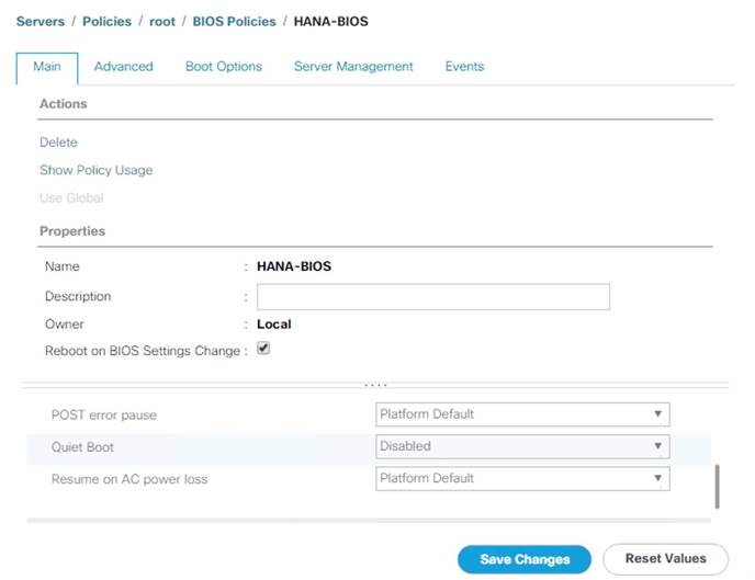
9. Click the Advanced Tab.
10. The recommendation from SAP for SAP HANA is to disable all Processor C States. This will force the CPU to stay on maximum frequency and allow SAP HANA to run with best performance.
11. On the Advanced tab, under Processor sub-tab, make sure Processor C State is disabled.
12. Set HPC for CPU Performance, Performance for Power Technology, Performance for Energy Performance.
Figure 21 Processor Settings in BIOS Policy
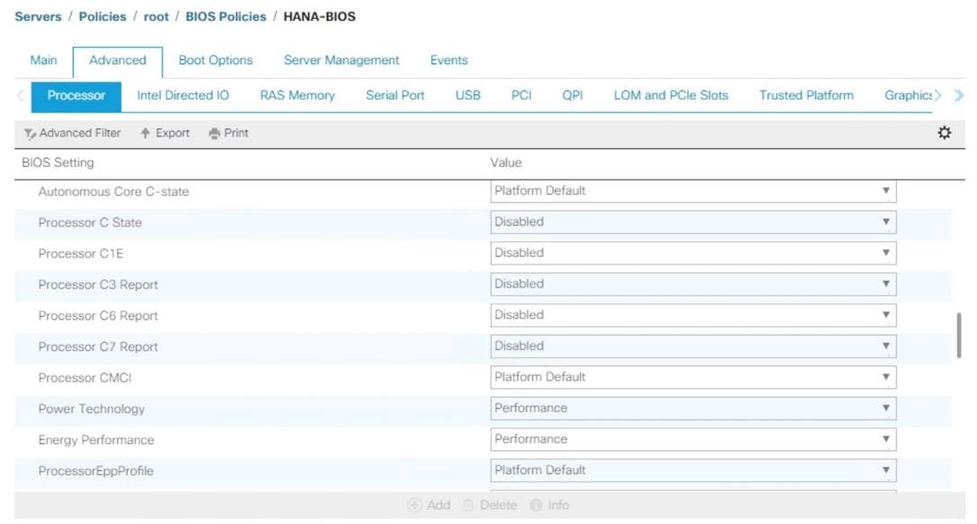
13. In the RAS Memory tab, select Performance Mode for LV DDR Mode, enabled for NUMA optimized and maximum-performance for Memory RAS configuration
Figure 22 BIOS Policy – Advanced - RAS Memory
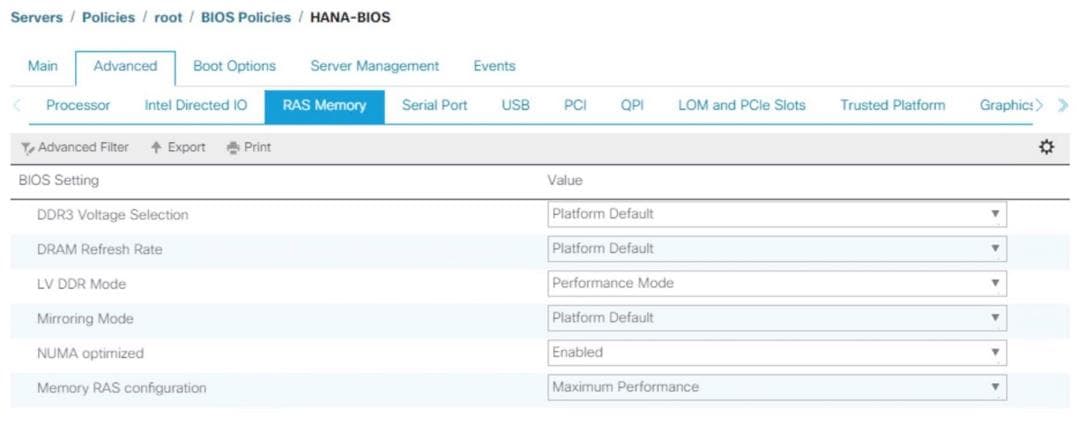
14. In the Serial Port sub-tab, the Serial Port A enable must be set to Enabled.
15. On the Server Management tab, select 115.2k for BAUD Rate, Serial Port A for Console redirection, Enabled for Legacy OS redirection, VT100-PLUS for Terminal type. This is used for Serial Console Access over LAN to all SAP HANA servers.
Figure 23 BIOS Policy – Server Management
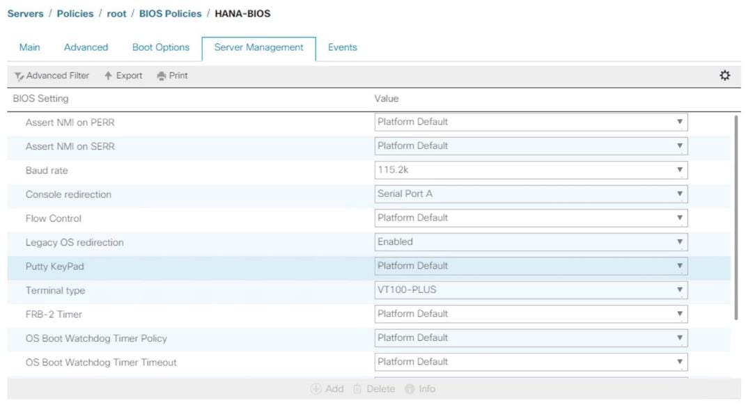
16. Click Save Change to modify BIOS Policy.
17. Click OK.
Power Control Policy
The Power Capping feature in Cisco UCS is designed to save power with a legacy data center use case. This feature does not contribute much to the high-performance behavior of SAP HANA. By choosing the option “No Cap” for power control policy, the SAP HANA server nodes will not have a restricted power supply. It is recommended to have this power control policy to make sure sufficient power supply for high performance and critical applications like SAP HANA.
To create a power control policy for the Cisco UCS environment, follow these steps:
1. In Cisco UCS Manager, click the Servers tab in the navigation pane.
2. Select Policies > root.
3. Right-click Power Control Policies.
4. Select Create Power Control Policy.
5. Enter HANA as the Power Control Policy name. (Optional) provide description.
6. Set Fan Speed Policy to Performance.
7. Change the Power Capping setting to No Cap.
Figure 24 Power Control Policy for SAP HANA Nodes
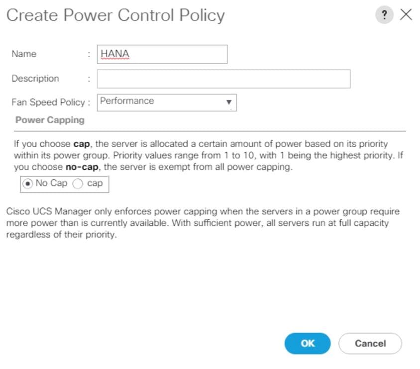
8. Click OK to create the power control policy.
9. Click OK
Create Serial over LAN Policy
The Serial over LAN policy is required to get console access to all the SAP HANA servers through SSH from the management network. This is used in case of the server hang or a Linux kernel crash, where the dump is required. To configure Create Serial over LAN Policy, follow these steps:
1. In Cisco UCS Manager, click the Servers tab in the navigation pane.
2. Select Policies > root
3. Right-click the Serial over LAN Policies.
4. Select Create Serial over LAN Policy.
5. Enter SoL-Console as the Policy name.
6. Select Serial over LAN State to Enable.
7. Change the Speed to 115200.
8. Click OK.
Figure 25 Serial Over LAN Policy
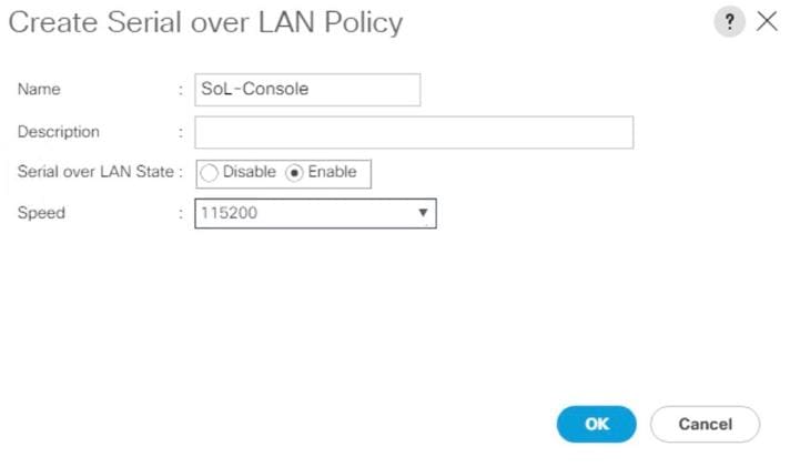
Update Default Maintenance Policy
It is recommended to update the default Maintenance Policy with the Reboot Policy “User Ack” for the SAP HANA server. This policy will wait for the administrator to acknowledge the server reboot for the configuration changes to take effect.
To update the default Maintenance Policy, follow these steps:
1. In Cisco UCS Manager, click the Servers tab in the navigation pane.
2. Select Policies > root.
3. Select Maintenance Policies > default.
4. Change the Reboot Policy to User Ack.
5. Click Save Changes.
6. Click OK to accept the change.
Figure 26 Maintenance Policy
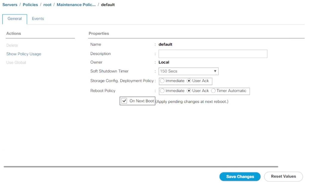
Network Control Policy
Update Default Network Control Policy to Enable CDP
CDP needs to be enabled to learn the MAC address of the End Point. To update default Network Control Policy, follow these steps:
1. In Cisco UCS Manager, click the LAN tab in the navigation pane.
2. Select LAN > Policies > root > Network Control Policies > default.
3. In the right pane, click the General tab.
4. For CDP: select Enabled radio button.
5. Click Save Changes in the bottom of the window.
6. Click OK.
Figure 27 Network Control Policy to Enable CDP
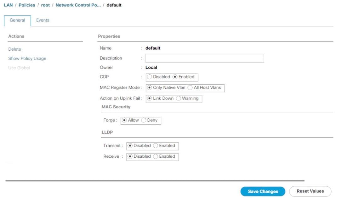
Configure Cisco UCS LAN Connectivity
Set Jumbo Frames in Cisco UCS Fabric
The core network requirements for SAP HANA are covered by Cisco UCS defaults. Cisco UCS is based on 40GbE and provides redundancy through the Dual Fabric concept. The Service Profile is configured to distribute the traffic across Fabric Interconnect A and B.
To configure jumbo frames and enable quality of service in the Cisco UCS fabric, follow these steps:
1. In Cisco UCS Manager, click the LAN tab in the navigation pane.
2. Select LAN > LAN Cloud > QoS System Class.
3. In the right pane, click the General tab.
4. On the MTU Column, enter 9216 in the box.
5. Click Save Changes in the bottom of the window.
6. Click Yes to accept the QoS Change Warning
7. Click OK.
Figure 28 Cisco UCS – Setting Jumbo Frames
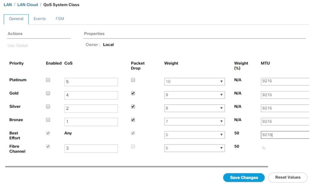
Create LAN Uplink Port Channels
Configure the LAN uplinks from FI-A and FI-B towards northbound Nexus Switches, in port-channel, for use by all of the network zones as prescribed by SAP. For example, we create port-channel 21 on FI-A and port-channel 22 on FI- B. This port channel pair will have corresponding vPCs defined on N9Ks that ensures seamless redundancy and failover for the north-south network traffic
It would suffice to have a port-channel pair on FI with corresponding vPC pair on N9Ks to handle traffic of all network zones provided we have enough ports to account for the desired bandwidth. In the current example, we have used two pairs of 2 x 40GE ports for the FI<->N9K connectivity for port-channels. You could add more based on the need or use-case.
We create port channel pair 21 and 22 with two 40GE ports from FIs to the Nexus switches to cater to SAP HANA’s Client, Admin and Internal zones.
We create another port channel pair 31 and 32 with two 40GE ports from FIs to the Nexus switches that could exclusively handle bandwidth intensive SAP HANA Storage zone traffic comprising of HANA node backup network.
To configure the necessary port channels out of the Cisco UCS environment, follow these steps:
1. In this procedure, two port channels are created: one each from FI-A to and FI-B to uplink Cisco Nexus switches.
2. In Cisco UCS Manager, click the LAN tab in the navigation pane
3. Under LAN > LAN Cloud, expand the Fabric A tree.
4. Right-click Port Channels.
5. Select Create Port Channel.
Figure 29 Cisco UCS – Creating Ethernet Port Channel
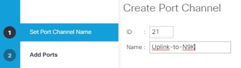
6. Enter 21 as the unique ID of the port channel.
7. Enter Uplink-to-N9K as the name of the port channel.
8. Click Next.
9. Select the following ports to be added to the port channel:
- Slot ID 1 and port 33
- Slot ID 1 and port 34
![]() The ports are selected based on Uplink Port connectivity and are specific to this sample configuration.
The ports are selected based on Uplink Port connectivity and are specific to this sample configuration.
Figure 30 Cisco UCS Port Channel – Add ports
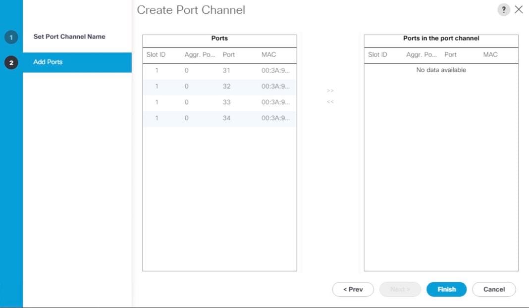
10. Click >> to add the ports to the port channel.
11. Click Finish to create the port channel.
12. Click OK.
13. In the navigation pane, under LAN > LAN Cloud, expand the Fabric B tree.
14. Right-click Port Channels.
15. Select Create Port Channel.
16. Enter 22 as the unique ID of the port channel.
17. Enter Uplink-to-N9K as the name of the port channel.
18. Click Next.
19. Select the following ports to be added to the port channel:
- Slot ID 1 and port 33
- Slot ID 1 and port 34
20. Click >> to add the ports to the port channel.
21. Click Finish to create the port channel.
22. Click OK.
![]() Configure a second set of port-channels from FI-A and FI-B to the nexus switches. This uplink port-channel could be exclusively used for backup network traffic.
Configure a second set of port-channels from FI-A and FI-B to the nexus switches. This uplink port-channel could be exclusively used for backup network traffic.
23. In Cisco UCS Manager, click the LAN tab in the navigation pane
24. Under LAN > LAN Cloud, expand the Fabric A tree.
25. Right-click Port Channels.
26. Select Create Port Channel.
Figure 31 Cisco UCS – Creating Ethernet Port Channel
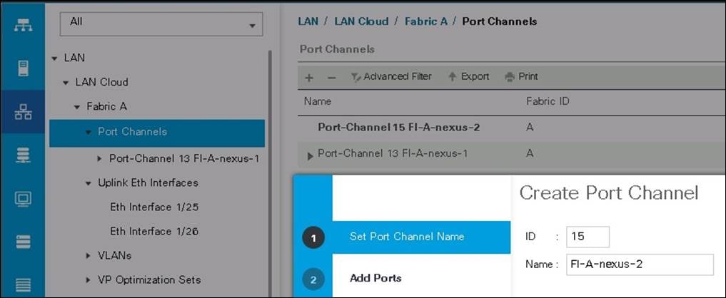
27. Enter 31 as the unique ID of the port channel.
28. Enter Uplink-Backup as the name of the port channel.
29. Click Next.
30. Select the following ports to be added to the port channel:
- Slot ID 1 and port 31
- Slot ID 1 and port 32
![]() The ports are selected based on Uplink Port connectivity and are specific to this sample configuration.
The ports are selected based on Uplink Port connectivity and are specific to this sample configuration.
Figure 32 Cisco UCS Port Channel – Add Ports
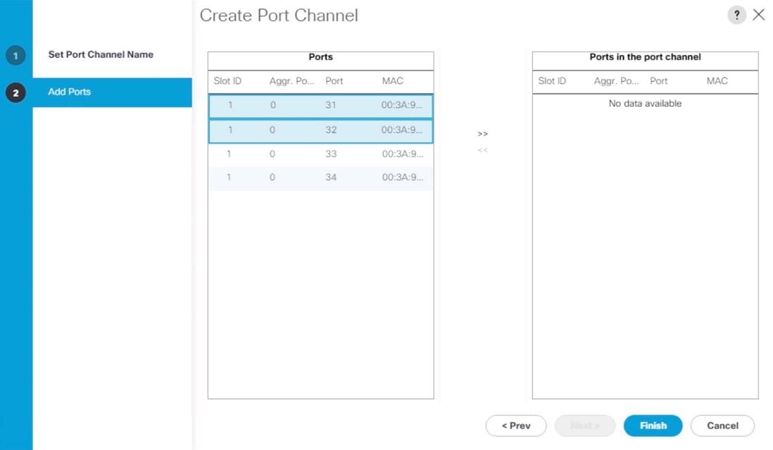
31. Click >> to add the ports to the port channel.
32. Click Finish to create the port channel.
33. Click OK.
34. In the navigation pane, under LAN > LAN Cloud, expand the Fabric B tree.
35. Right-click Port Channels.
36. Select Create Port Channel
37. Enter 31 as the unique ID of the port channel.
38. Enter Uplink-Backup as the name of the port channel.
39. Click Next.
40. Select the following ports to be added to the port channel:
- Slot ID 1 and port 31
- Slot ID 1 and port 32
41. Click >> to add the ports to the port channel.
42. Click Finish to create the port channel.
43. Click OK.
Figure 33 Cisco UCS FI-A Port Channel Overview
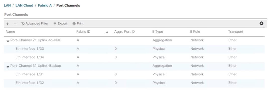
Figure 34 Cisco UCS FI-B Port Channel Overview
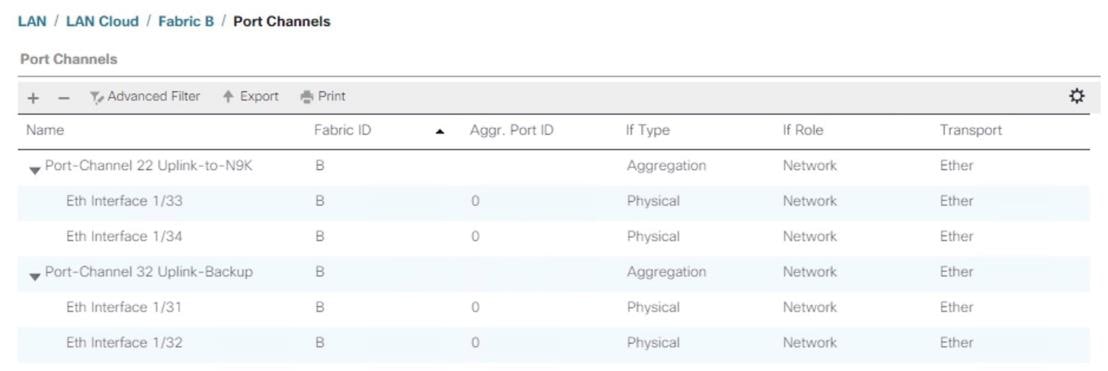
VLAN Configurations
Within Cisco UCS, all the network types for an SAP HANA system are manifested by defined VLANs. Even though six VLANs are defined, VLANs for all the networks are not necessary if the solution will not use those networks. For example, if the Replication Network is not used in the solution, then VLAN ID 225 need not be created.
The VLAN IDs can be changed if required to match the VLAN IDs in the customer’s network – for example, ID 221 for backup should match the configured VLAN ID at the customer uplink network switches.
Create VLANs
To configure the necessary VLANs for the Cisco UCS environment, follow these steps:
1. In Cisco UCS Manager, click the LAN tab in the navigation pane.
![]() In this procedure, six VLANs are created.
In this procedure, six VLANs are created.
2. Select LAN > LAN Cloud.
3. Right-click VLANs.
4. Select Create VLANs.
5. Enter HANA-Mgmt as the name of the VLAN to be used for Management network.
6. Keep the Common/Global option selected for the scope of the VLAN.
7. Enter <<var_mgmt_vlan_id>> as the ID of the Management network.
8. Keep the Sharing Type as None.
9. Click OK, and then click OK again.
Figure 35 Create VLAN for Internode
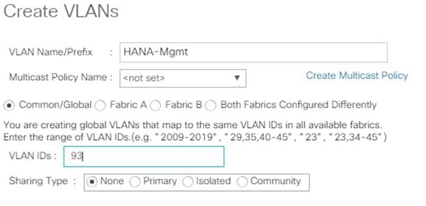
10. Repeat steps 1-9 above for each VLAN creation.
11. Create VLAN for HANA-Backup
Figure 36 Create VLAN for Backup
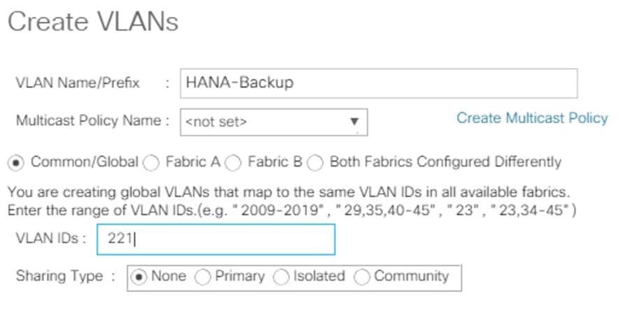
12. Create VLAN for HANA-Client.
Figure 37 Create VLAN for Client Network
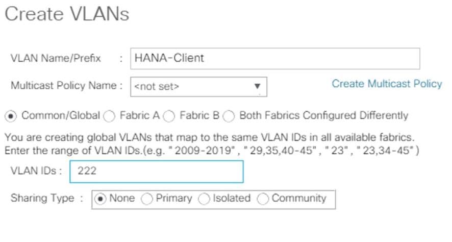
13. Create VLAN for HANA-AppServer.
Figure 38 Create VLAN for Application Server

14. Create VLAN for HANA-DataSource.
Figure 39 Create VLAN for Data Source
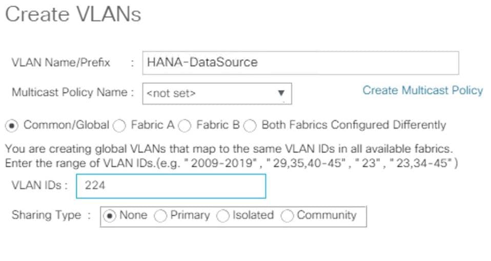
15. Create VLAN for HANA-Replication.
Figure 40 Create VLAN for Replication
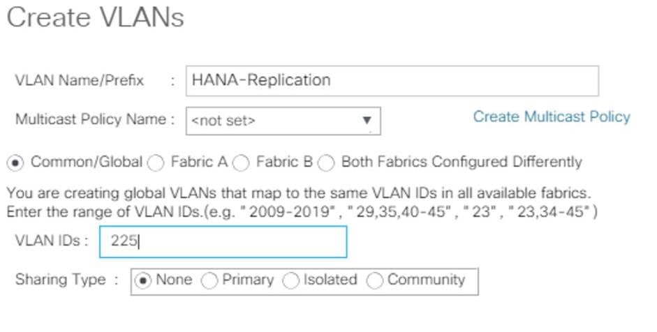
The list of created VLANs is shown below:
Figure 41 VLAN Definition in Cisco UCS
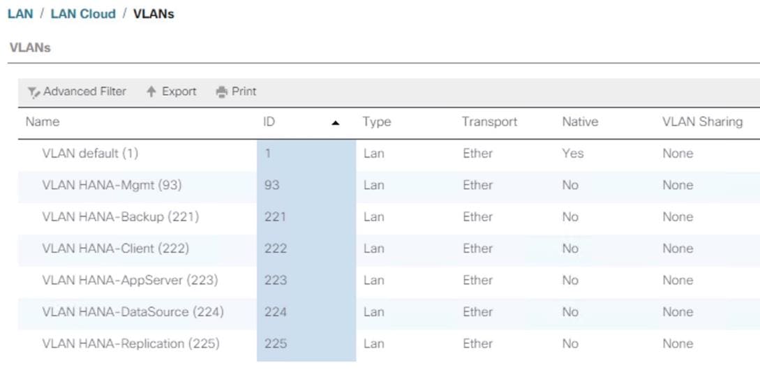
Create VLAN Groups
For easier management and bandwidth allocation to a dedicated uplink on the Fabric Interconnect, VLAN Groups are created within the Cisco UCS. SAP groups the networks needed by HANA system into following zones which could be translated to VLAN groups in Cisco UCS configuration:
· Client Zone – including AppServer, Client and DataSource networks
· Internal Zone – including Inter-node and System Replication networks
· Storage Zone – including Backup and IP storage networks
· And optional Admin zone – including Management, , OS cluster network, if any
To configure the necessary VLAN Groups for the Cisco UCS environment, follow these steps:
1. In Cisco UCS Manager, click the LAN tab in the navigation pane.
![]() In this procedure, three VLAN Groups are created. Based on the solution requirement create VLAN groups as needed by the implementation scenario.
In this procedure, three VLAN Groups are created. Based on the solution requirement create VLAN groups as needed by the implementation scenario.
2. Select LAN > LAN Cloud.
3. Right-click VLAN Groups.
4. Select Create VLAN Groups.
5. Enter Admin-Zone as the name of the VLAN Group used for Infrastructure network.
6. Select HANA-Mgmt.
Figure 42 Create VLAN Group for Admin Zone
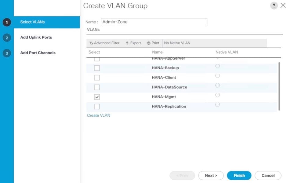
7. Click Next
8. Click Next on Add Uplink Ports, since you will use port-channel.
9. Choose port-channels created [21 & 22 in this example configuration] for uplink network. Click >>
Figure 43 Add Port-Channel for VLAN Group Admin Zone
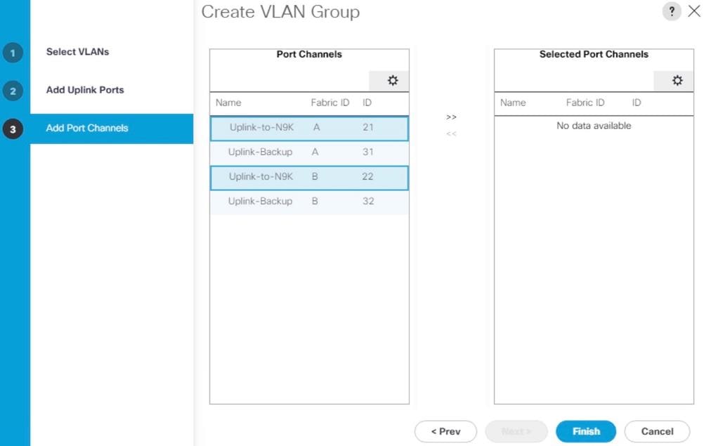
10. Click Finish.
11. Create VLAN Group for Client Zone. Select HANA-AppServer, HANA-Client and HANA-DataSource networks to be part of this VLAN group.
Figure 44 Create VLAN Group for Client Zone
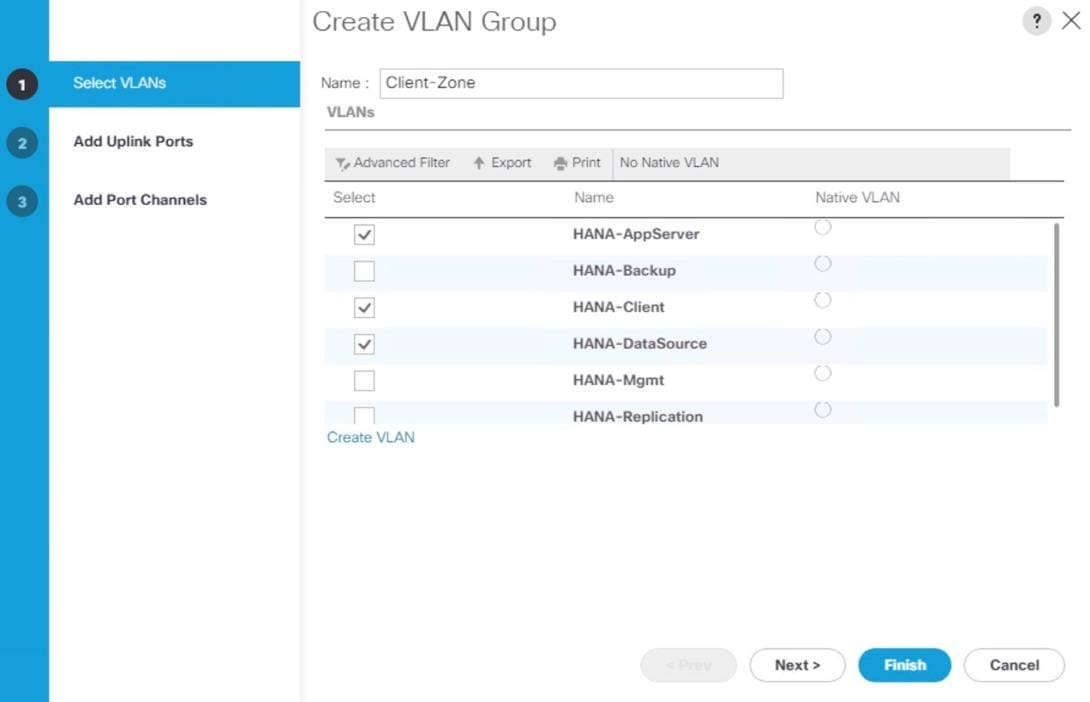
12. Click Next.
13. Click Next on Add Uplink Ports, since you will use port-channel.
14. Choose port-channels (21 and 22 in this example configuration) created for uplink network. Click >>
Figure 45 Add Port-Channel for VLAN Group Internal Zone
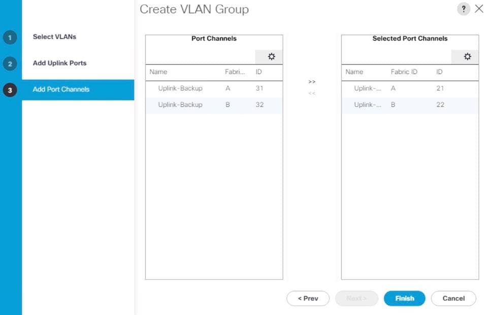
15. Click Finish.
16. Create VLAN Group for Backup Network. Select HANA-Backup network.
Figure 46 Create VLAN Group for Backup Network
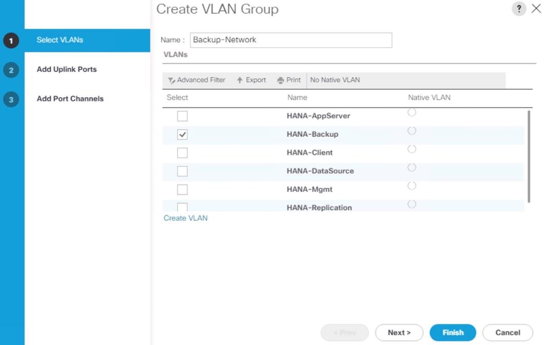
17. Click Next.
18. Click Next on Add Uplink Ports, since you will use port-channel.
19. Choose port-channels (31 and 32 in this example configuration) created for uplink network. Click >>
Figure 47 Add Port-Channel for VLAN Group Internal Zone
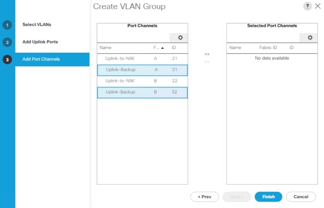
20. Click Finish
21. Create VLAN Group for Internal-Zone. Select HANA-Replication network
22. Click Next.
23. Click Next on Add Uplink Ports, since you will use port-channel.
24. Choose port-channels (21 and 22 in this example configuration) created for uplink network. Click >>
25. Click Finish
26. More VLAN groups, if needed could be created following the above steps. VLAN Groups created in the Cisco UCS.
Figure 48 VLAN Groups in Cisco UCS
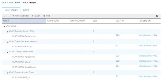
![]() For each VLAN Group a dedicated Ethernet Uplink Port or Port Channel can be selected, if the use-case demands. Alternatively, a single uplink Port Channel with more ports to enhance the bandwidth could also be used if that suffices.
For each VLAN Group a dedicated Ethernet Uplink Port or Port Channel can be selected, if the use-case demands. Alternatively, a single uplink Port Channel with more ports to enhance the bandwidth could also be used if that suffices.
Create vNIC Template
Each VLAN is mapped to a vNIC template to specify the characteristic of a specific network. The vNIC template configuration settings include MTU size, Failover capabilities and MAC-Address pools.
To create vNIC templates for the Cisco UCS environment, follow these steps:
1. In Cisco UCS Manager, click the LAN tab in the navigation pane.
2. Select Policies > root > Sub-Organization > T01-HANA.
3. Right-click vNIC Templates.
4. Select Create vNIC Template.
5. Enter HANA-Mgmt as the vNIC template name.
6. For Fabric ID select Fabric A and Check the Enable Failover checkbox.
7. Under Target, make sure that the VM checkbox is unchecked.
8. Select Updating Template as the Template Type.
9. Under VLANs, check the checkboxes for HANA-Mgmt.
10. Set HANA-Internal as the native VLAN.
11. For MTU, enter 9000.
12. In the MAC Pool list, select FI-A.
13. For Network Control Policy Select default from drop-down list.
Figure 49 Create vNIC Template for HANA-Mgmt
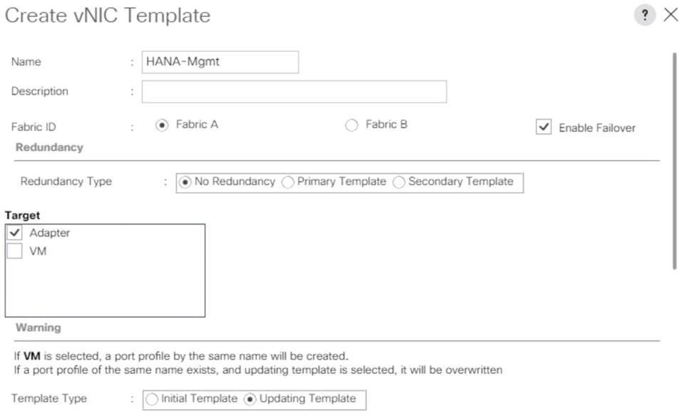
Figure 50 Create vNIC Template for HANA-Mgmt
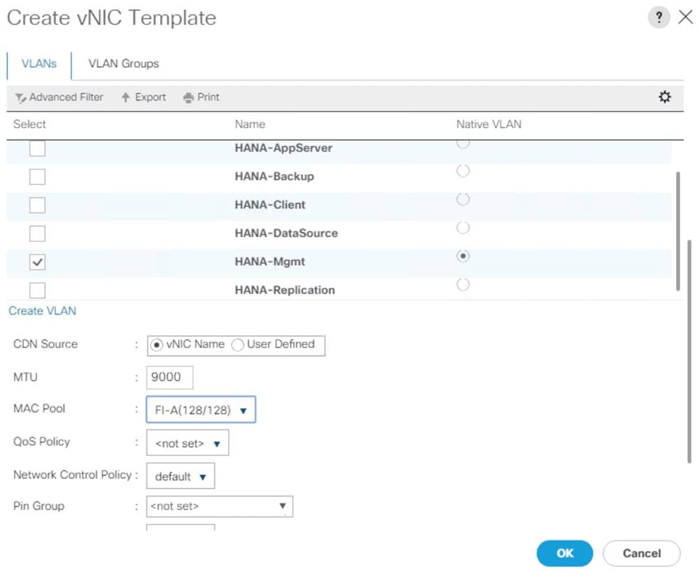
14. Click OK to create the vNIC template.
15. Click OK.
![]() For most SAP HANA use cases the network traffic is well distributed across the two Fabrics (Fabric A and Fabric B) using the default setup. In special cases, it can be required to rebalance this distribution for better overall performance. This can be done in the vNIC template with the Fabric ID setting. The MTU settings must match the configuration in customer data center. MTU setting of 9000 is recommended for best performance.
For most SAP HANA use cases the network traffic is well distributed across the two Fabrics (Fabric A and Fabric B) using the default setup. In special cases, it can be required to rebalance this distribution for better overall performance. This can be done in the vNIC template with the Fabric ID setting. The MTU settings must match the configuration in customer data center. MTU setting of 9000 is recommended for best performance.
16. Create vNIC template for each Network.
Create a vNIC Template for Client Network
To create a vNIC template for the client network, follow these steps:
1. Select Policies > root > Sub-Organization > T01-HANA.
2. Right-click vNIC Templates and select Create vNIC Template.
3. Enter HANA-Client as the vNIC template name.
4. For Fabric ID select Fabric B and Check the Enable Failover checkbox.
5. Under Target, make sure that the VM checkbox is unchecked.
6. Select Updating Template as the Template Type.
7. Under VLANs, check the checkboxes for HANA-Client.
8. Set HANA-Client as the native VLAN.
9. For MTU, enter 9000.
10. In the MAC Pool list, select FI-B
11. For Network Control Policy Select default from drop-down list.
12. Click OK to create the vNIC template.
Create a vNIC Template for Application Server Network
To create a vNIC template for the application server network, follow these steps:
1. Select Policies > root > Sub-Organization > T01-HANA.
2. Right-click vNIC Templates and select Create vNIC Template.
3. Enter HANA-AppServer as the vNIC template name.
4. For Fabric ID select Fabric A and Check the Enable Failover checkbox.
5. Under Target, make sure that the VM checkbox is unchecked.
6. Select Updating Template as the Template Type.
7. Under VLANs, check the checkboxes for HANA-AppServer.
8. Set HANA-AppServer as the native VLAN.
9. For MTU, enter 9000.
10. In the MAC Pool list, select FI-A
11. For Network Control Policy Select default from drop-down list.
12. Click OK to create the vNIC template.
Create a vNIC Template for DataSource Network
To create a vNIC template for the DataSource network, follow these steps:
1. Select Policies > root > Sub-Organization > T01-HANA.
2. Right-click vNIC Templates and select Create vNIC Template.
3. Enter HANA-DataSource as the vNIC template name.
4. For Fabric ID select Fabric A and Check the Enable Failover checkbox.
5. Under Target, make sure that the VM checkbox is unchecked.
6. Select Updating Template as the Template Type.
7. Under VLANs, check the checkboxes for HANA-DataSource.
8. Set HANA-DataSource as the native VLAN.
9. For MTU, enter 9000.
10. In the MAC Pool list, select FI-A
11. For Network Control Policy Select default from drop-down list.
12. Click OK to create the vNIC template
Create a vNIC Template for Replication Network
To create a vNIC template for the replication network, follow these steps:
1. Select Policies > root > Sub-Organization > T01-HANA.
2. Right-click vNIC Templates and select Create vNIC Template.
3. Enter HANA-Replication as the vNIC template name.
4. For Fabric ID select Fabric B and Check the Enable Failover checkbox.
5. Under Target, make sure that the VM checkbox is unchecked.
6. Select Updating Template as the Template Type.
7. Under VLANs, check the checkboxes for HANA-Replication
8. Set HANA-Replication as the native VLAN.
9. For MTU, enter 9000.
10. In the MAC Pool list, select FI-B
11. For Network Control Policy Select default from drop-down list.
12. Click OK to create the vNIC template.
Create a vNIC Template for Backup Network
To create a vNIC template for the backup network, follow these steps:
1. Select Policies > root > Sub-Organization > T01-HANA.
2. Right-click vNIC Templates and select Create vNIC Template.
3. Enter HANA-Backup as the vNIC template name.
4. For Fabric ID select Fabric B and Check the Enable Failover checkbox.
5. Under Target, make sure that the VM checkbox is unchecked.
6. Select Updating Template as the Template Type.
7. Under VLANs, check the checkboxes for HANA-Backup
8. Set HANA-Backup as the native VLAN.
9. For MTU, enter 9000.
10. In the MAC Pool list, select FI-B
11. For Network Control Policy Select default from drop-down list.
12. Click OK to create the vNIC template.
The figure below shows the list of vNIC Templates created for SAP HANA.
Figure 51 vNIC Templates Overview
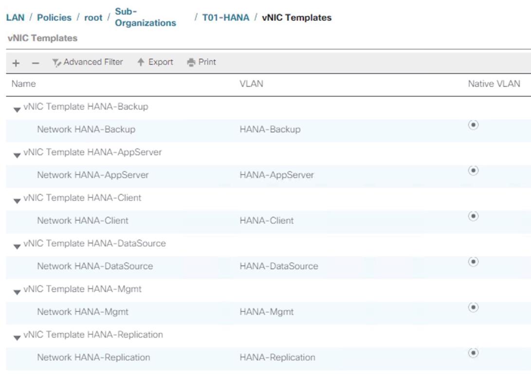
Configure Cisco UCS SAN Configurations
Create FC Port Channels
Create a port channel on FIs A and B for the uplink FC interfaces that connect to respective MDS Fabric Switches, for use by all of the specific VSAN traffic we created earlier in MDS. This port channel pair will have corresponding F-port-channel-trunks defined on MDS switches that would allow for the fabric logins from NPV enabled FIs to be virtualized over the port channel. This provides non-disruptive redundancy should individual member links fail.
To configure the necessary port channels out of the Cisco UCS environment, follow these steps:
1. In this procedure, two port channels are created: one from fabric A to both Cisco Nexus switches and one from fabric B to both Cisco Nexus switches.
2. In Cisco UCS Manager, click the SAN tab in the navigation pane.
3. Under SAN > SAN Cloud, expand the Fabric A tree.
4. Right-click FC Port Channels.
5. Select Create FC Port Channel.
Figure 52 Cisco UCS – Creating FC Port Channel
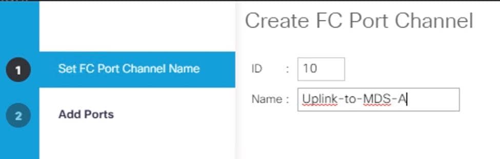
6. Enter 10 as the unique ID of the port channel.
7. Enter Uplink-to-MDS-A as the name of the port channel.
8. Click Next.
9. Set Port Channel Admin Speed to 16gbps. Select the following ports to be added to the port channel:
- Slot ID 1 and port 1
- Slot ID 1 and port 2
- Slot ID 1 and port 3
- Slot ID 1 and port 4
![]() The ports are selected based on Uplink Port connectivity and hence very specific to this sample configuration.
The ports are selected based on Uplink Port connectivity and hence very specific to this sample configuration.
Figure 53 Cisco UCS – Port Channel – Add Ports
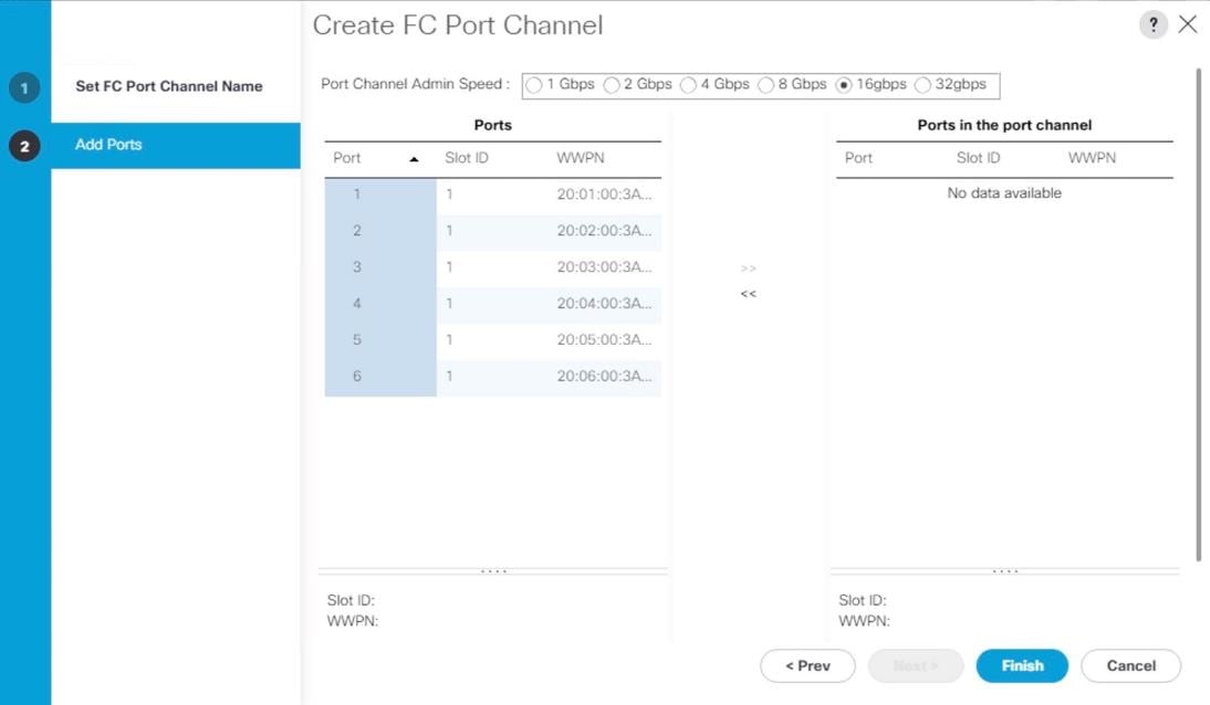
10. Click >> to add the ports to the port channel.
11. Click Finish to create the port channel.
12. Click OK.
13. In the navigation pane, under SAN > SAN Cloud, expand the Fabric B tree.
14. Right-click FC Port Channels.
15. Select Create FC Port Channel.
16. Enter 20 as the unique ID of the port channel.
17. Enter Uplink-to-MDS-B as the name of the port channel.
18. Click Next.
19. Set Port Channel Admin Speed to 16gbps. Select the following ports to be added to the port channel:
- Slot ID 1 and port 1
- Slot ID 1 and port 2
- Slot ID 1 and port 3
- Slot ID 1 and port 4
20. Click >> to add the ports to the port channel.
21. Click Finish to create the port channel.
22. Click OK.
Create VSANs
To configure the necessary VSANs for the Cisco UCS environment, follow these steps:
![]() In this procedure, two VSANs are created. One each for Fabric A and Fabric B.
In this procedure, two VSANs are created. One each for Fabric A and Fabric B.
1. In Cisco UCS Manager, click the SAN tab in the navigation pane.
2. Select SAN > SAN Cloud.
3. Right-click VSANs.
4. Select Create VSAN.
5. Enter Fab-A as the name of the VSAN to be used for Fabric A.
6. Retain ‘Disabled’ for FC Zoning option and select Fabric A.
7. Enter <<var_fabric-A_vsan_id>> as the ID of the VSAN ID. Use the same value for FCOE VLAN ID.
8. Click OK and then click OK again.
Figure 54 Create VSAN for Fabric A
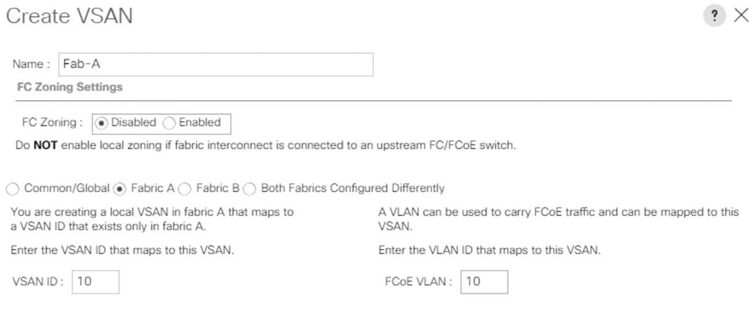
9. Select SAN > SAN Cloud.
10. Right-click VSANs.
11. Select Create VSANs.
12. Enter Fab-B as the name of the VSAN to be used for Fabric-B.
13. Retain ‘Disabled’ for FC Zoning option and select Fabric B.
14. Enter <<var_fabric-B_vsan_id>> as the ID of the VSAN ID. Use the same value for FCOE VLAN ID.
15. Click OK and then click OK again.
Figure 55 VSANs for Fabrics
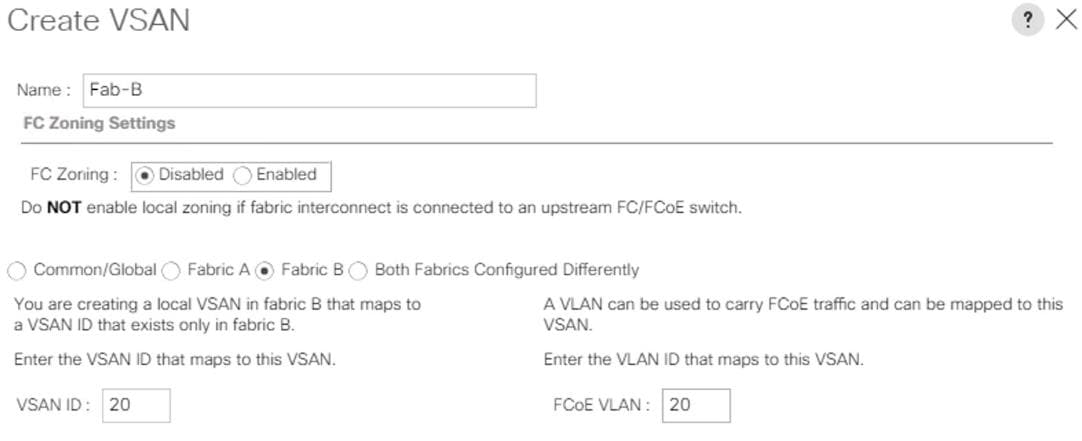
Assign Respective Fabric FC Channels to Created VSAN
To assign the fc port channels to the fabric VSAN that you just created, follow these steps:
1. In Cisco UCS Manager, click the SAN tab > SAN Cloud > Fabric A> FC Port Channels>
2. Select the configured FC Port Channel.
3. On the right pane, change the VSAN information from default (1) to Fab-A VSAN 10 created for Fabric-A.
Figure 56 VSAN Membership for FI-A FC Uplink Port Channel
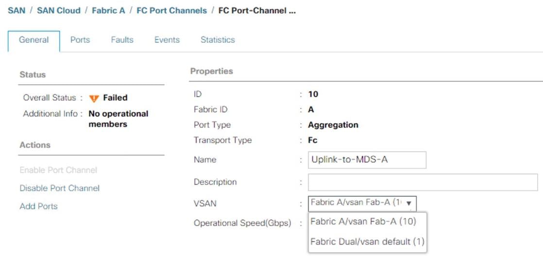
4. Select Save changes. Click OK. After the settings are saved, the Port Channel status changes to Up.
5. Click the SAN tab > SAN Cloud > Fabric B > FC Port Channels >.
6. Select the configured FC Port Channel.
7. On the right pane, change the VSAN information from default (1) to Fab-B VSAN 20 created for Fabric-B.
8. Select Save changes. Click OK.
Figure 57 VSAN Membership Setting for FI-B FC Uplink Port Channel
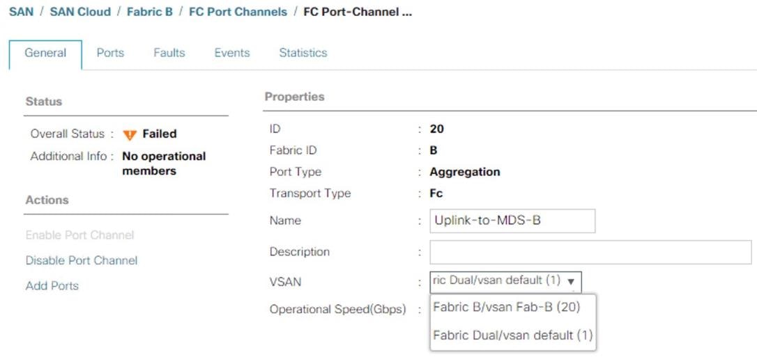
Create vHBA Template
![]() In this procedure, two vHBA templates are created. One each for Fabric A and Fabric B.
In this procedure, two vHBA templates are created. One each for Fabric A and Fabric B.
1. In Cisco UCS Manager, click on tab SAN > Policies > root > Sub-Organizations > T01-HANA.
2. Right-click on vHBA Templates to “Create vHBA Template.”
3. First create a template for Fabric A. Choose vHBA-A for name.
4. Optionally provide a description.
5. Select Fabric ID A
6. Select VSAN Fab-A
7. Template Type as Updating template.
8. Select WWPN Pool FI-A.
9. Click Ok and Click OK.
Figure 58 Fabric A - vHBA Template
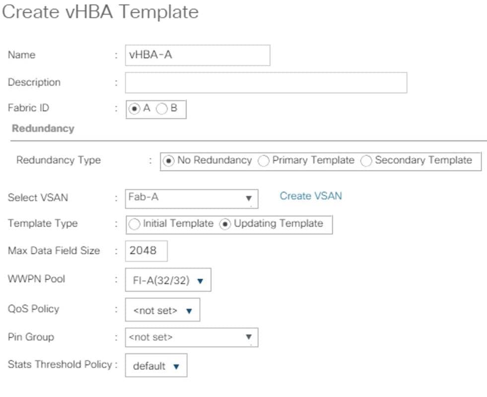
10. Create a template for Fabric B. Choose vHBA-B for name.
11. In Cisco UCS Manager, click on tab SAN > Policies > root > Sub-Organizations > HANA.
12. Right-click on vHBA Templates to “Create vHBA Template.”
13. Choose vHBA-B for name.
14. Optionally provide a description.
15. Select Fabric ID B.
16. Select VSAN Fab-B
17. Template Type as Updating template.
18. Select WWPN Pool as FI-B.
19. Click Ok and Click OK.
Figure 59 Fabric B - vHBA Template
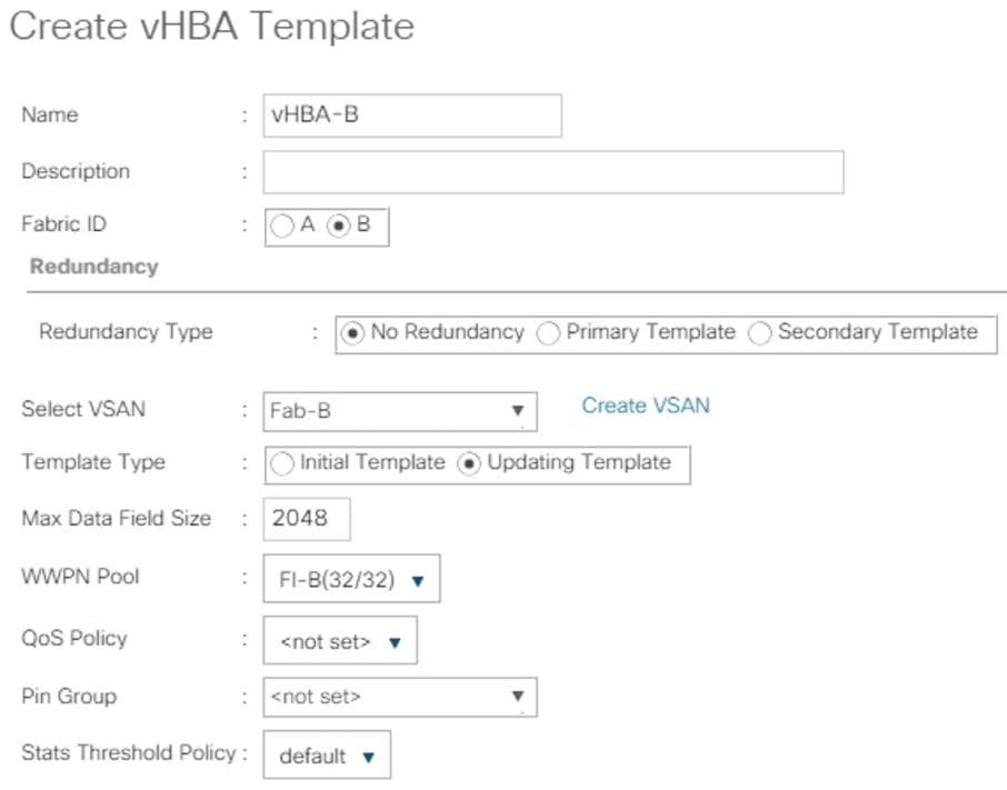
Create SAN Connectivity Policy
When the physical connectivity is established, the following will configure the zoning for the servers and SAN:
· Storage connection policies: This configures the storage connectivity taking into account the WWPN Target numbers for the SAN. Since the Zoning is handled by the MDS switches and that FIs aren’t direct attached to the Storage, we do not configure this Storage side connection policy.
· SAN connectivity policies configuration: This configures vHBAs for the servers which will provide WWPN Initiator numbers for the servers. This server-side configuration is needed to prepare the servers for connection to storage.
To configure the storage connection policy, follow these steps:
1. Log into UCS Manager.
2. Click the SAN tab in the Navigation pane.
3. SAN tab > Policies > root > Sub-Organizations > HANA > SAN Connectivity Policies.
4. Right-click on SAN Connectivity Policies > Create SAN Connectivity Policy.
5. Provide name as HANA-SAN.
6. Optionally add a Description.
7. Select HANA-Servers for WWNN Assignment
Figure 60 Create SAN Connectivity Policy
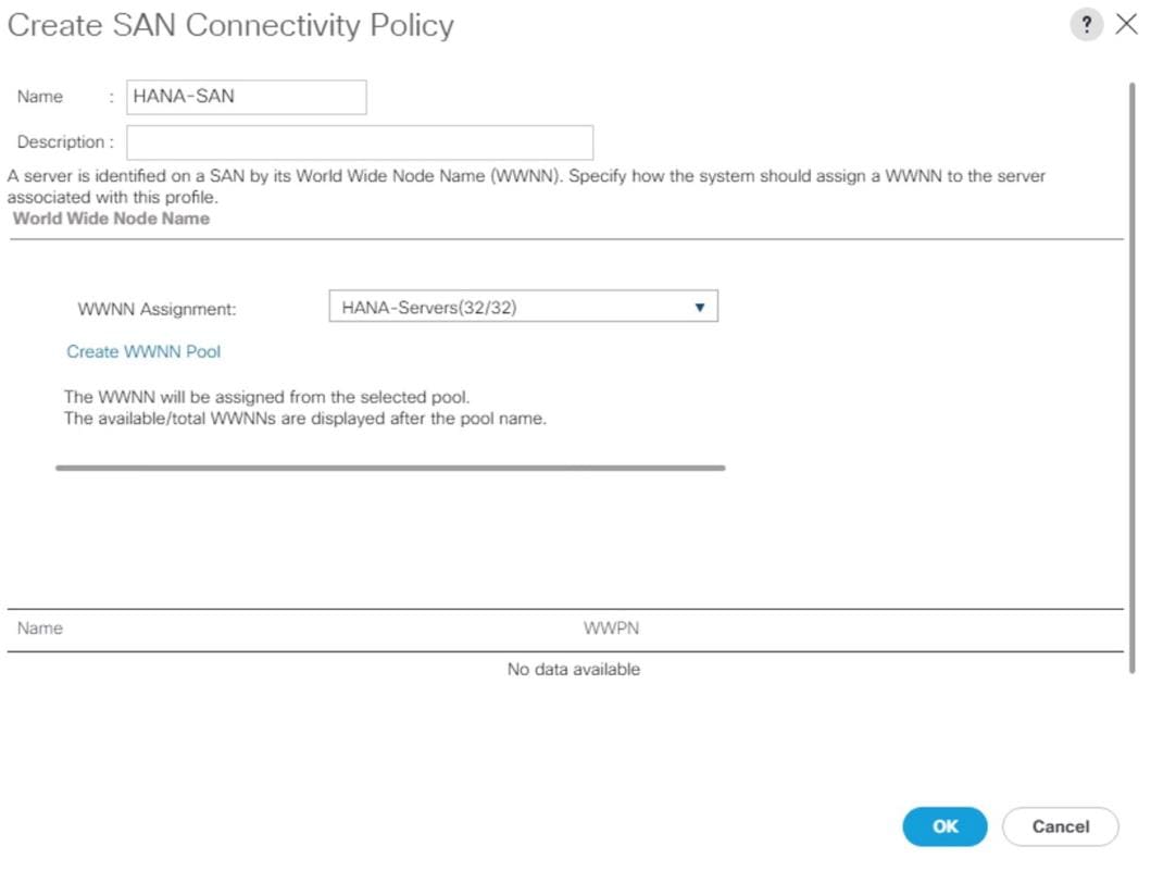
8. Click Add at the bottom for WWPN to add the vHBAs from the vHBA templates previously created.
9. In the Create vHBA window, provide a name as vhba-a and check “Use vHBA Template” option. Select vHBA-A from the vHBA Template drop-down list and Linux for the Adapter Policy. Click OK.
Figure 61 Create vHBA for Fabric A
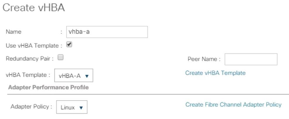
10. Click Add at the bottom for WWPN to add the vHBAs to add another vHBA.
11. In the Create vHBA window, provide name as vhba-b and check “Use vHBA Template” option. Select vHBA-B from the vHBA Template drop-down list and Linux for the Adapter Policy.
Figure 62 Create vHBA for Fabric B
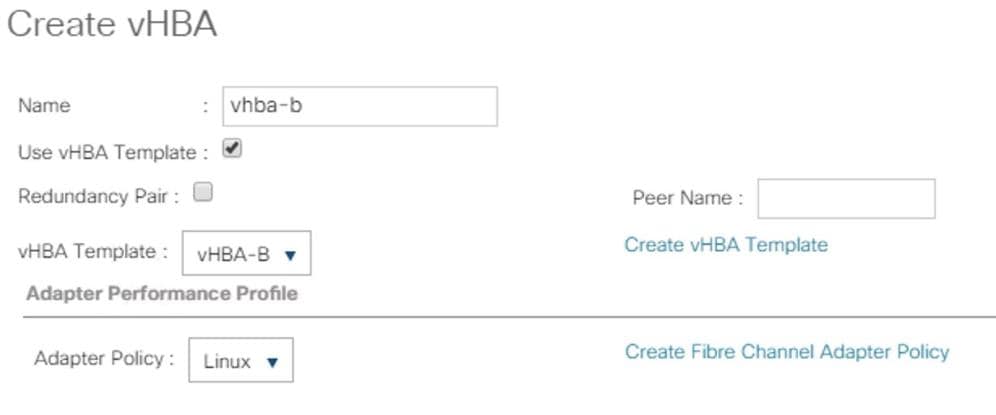
12. Click OK.
Figure 63 SAN Connectivity Policy (continued)
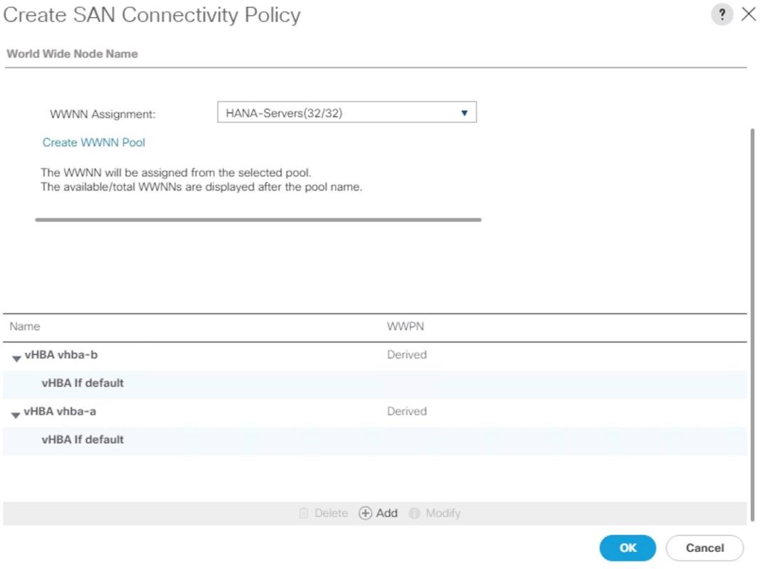
13. Click OK.
Create Boot Policy for SAN Boot
It is strongly recommended to use “Boot from SAN” to realize full benefits of Cisco UCS stateless computing feature such as service profile mobility. The ports on the storage controllers of Hitachi VSP are cross connected with the MDS switches so that we have alternate paths to the LUNs, in addition to the built-in redundancy and path management features of the storage array itself.
You can determine the WWPN information of these storage array target ports from the Hitachi Device Manager.
Configure the SAN primary's primary-target to be port CL1-A and SAN primary's secondary-target to be port CL2-A of the Hitachi VSP Storage. Similarly, the SAN secondary’s primary-target should be port CL3-A and SAN secondary's secondary-target should be port CL4-A
You have to create SAN Boot primary (hba0) and SAN Boot secondary (hba1) in create boot policy by entering WWPN of Hitachi Storage FC Ports.
To create boot policies for the Cisco UCS environments, follow these steps:
1. Go to tab Servers > Policies > root > Sub-Organizations > T01-HANA > Boot Policies.
2. Right-click Boot Policies and select Create Boot Policy
3. Enter HANA-SanBoot as the name of the boot policy
4. Make sure the “Enforce vNIC/vHBA/iSCSI Name” option is unchecked.
5. Expand the Local Devices drop-down menu and Choose Add CD-ROM.
6. Expand the vHBAs drop-down list and Choose Add SAN Boot. In the Add SAN Boot dialog box, select type as ‘Primary’ and enter "hba0" in the vHBA field and Click OK
7. From the vHBAs drop-down list choose “Add SAN Boot Target.”
8. Keep 0 as the value for Boot Target LUN. Enter the WWPN for FC port CL1-A of Hitachi VSP Storage and add click OK.
Figure 64 hba0 Primary Boot Target
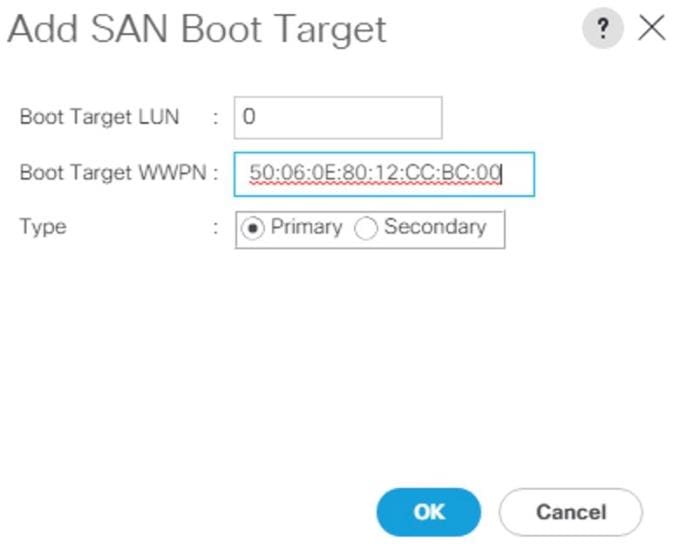
9. From the vHBAs drop-down menu choose “Add SAN Boot Target” To add a secondary SAN Boot target into hba0
10. Enter boot target LUN as 0 and WWPN for FC port CL2-A of Hitachi VSP Storage. Click OK.
11. From the vHBAs drop-down list and Choose Add SAN Boot. In the Add SAN Boot dialog box, enter "hba1" in the vHBA field. Click OK.
Figure 65 SAN Boot hba1
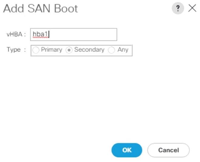
12. From the vHBAs drop-down list choose “Add SAN Boot Target.”
13. Keep 0 as the value for Boot Target LUN. Enter the WWPN for FC port CL2-A of Hitachi VSP Storage and add click OK.
14. From the vHBAs drop-down list choose “Add SAN Boot Target” to add a secondary SAN Boot target into hba1
15. Enter boot target LUN as 0 and WWPN for FC port CL4-A of Hitachi VSP Storage. Click OK.
16. Click OK and click OK for the Create Boot Policy pop-up.
17. After creating the FC boot policies, you can view the boot order in the Cisco UCS Manager GUI. To view the boot order, navigate to Servers > Policies > root > Sub-Organizations > T01-HANA > Boot Policies> HANA-SanBoot to view the boot order in the right pane of the Cisco UCS Manager as shown below.
Figure 66 SAN Boot Policy
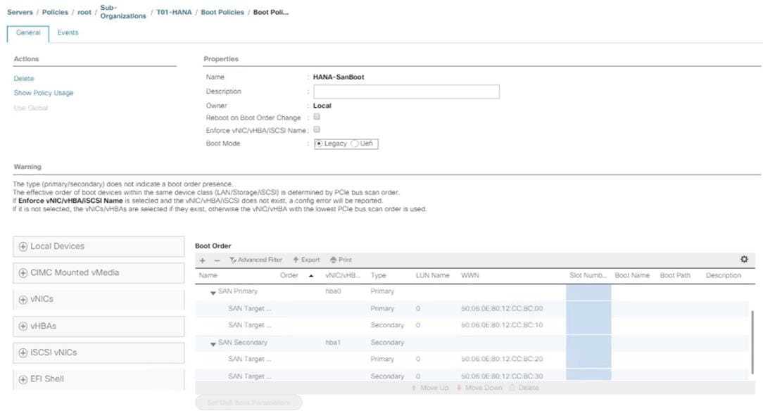
Create Service Profile Templates for SAP HANA Scale Up Servers
The LAN, SAN configurations and relevant SAP HANA policies must be defined prior to creating, a Service Profile Template.
To create the service profile template, follow these steps:
1. In Cisco UCS Manager, click the Servers tab in the navigation pane.
2. Select Service Profile Templates > root > Sub-Organization > T01-HANA.
3. Right-click T01-HANA Select Create Service Profile Template
4. This will pop-up Create Service Profile Template wizard
5. Enter HANA-ScaleUp as the name of the service profile template.
6. Select the Updating Template option from the Type
7. Under UUID, select HANA-UUID as the UUID pool. Optionally add a Description.
8. Click Next.
Figure 67 Service Profile Template UUID
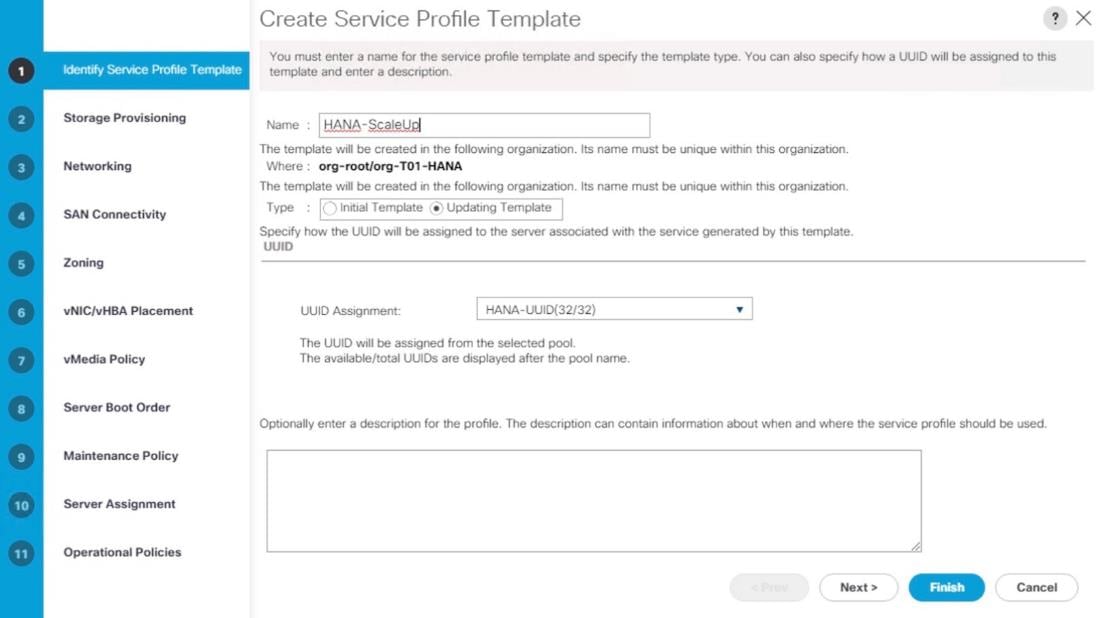
9. In the Storage Provisioning, nothing needs to be configured
10. Click Next.
11. In the Networking
12. Keep the default settings for Dynamic vNIC Connection Policy.
13. Select the Expert option for ‘How would you like to configure LAN connectivity’ question.
a. Click Add to add a vNIC to the template.
b. In the Create vNIC dialog box, enter HANA-AppServer as the name of the vNIC.
c. Check the Use vNIC Template checkbox.
d. In the vNIC Template list, select HANA-AppServer.
e. In the Adapter Policy list, select Linux.
f. Click OK to add this vNIC to the template.
Figure 68 Service Profile Template vNIC Internal
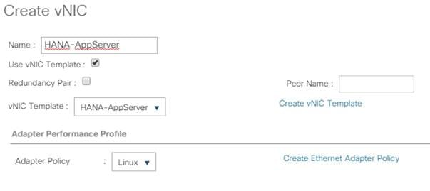
14. Repeat step 13 for each vNIC.
15. Add vNIC for HANA-Backup
Figure 69 Service Profile Template vNIC HANA-Backup
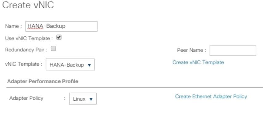
16. Add vNIC for HANA-Client.
Figure 70 Service Profile Template vNIC Hana-Client
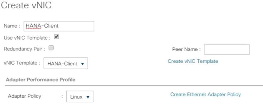
17. Add vNIC for HANA-DataSource.
Figure 71 Service Profile Template vNIC DataSource
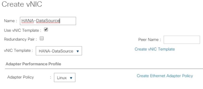
18. Add vNIC for Mgmt.
Figure 72 Service Profile Template vNIC Mgmt
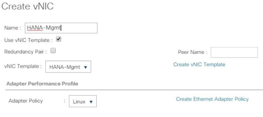
19. Add vNIC for HANA-Replication.
Figure 73 Service Profile Template vNIC Replication
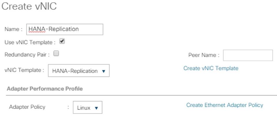
20. Review the table in the Networking pane to make sure that all vNICs were created.
Figure 74 Service Profile Networking
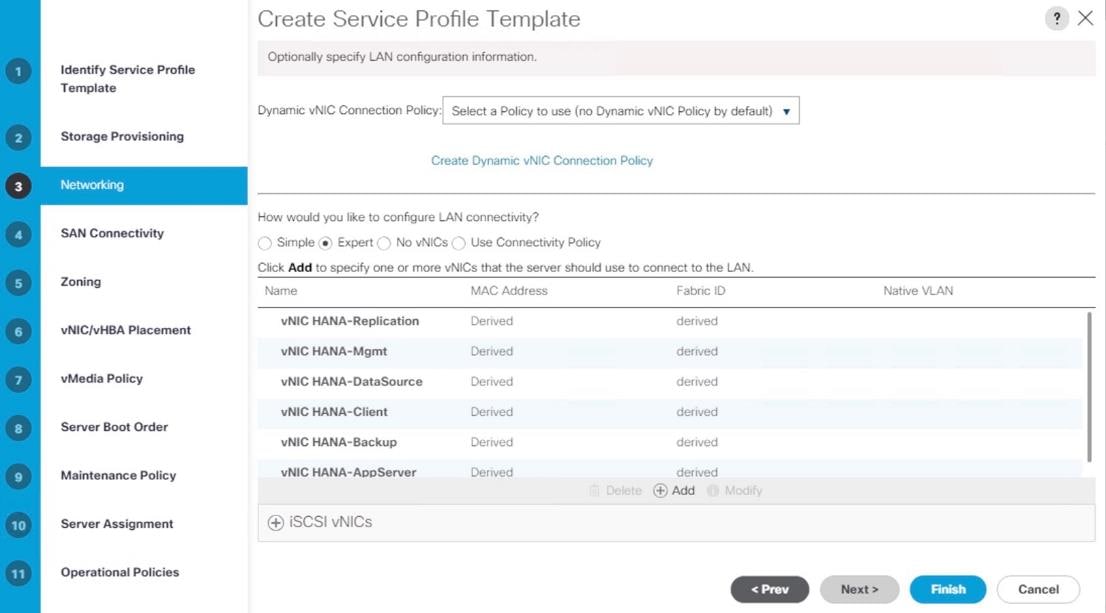
21. Click Next.
22. Configure the SAN Connectivity:
23. Select ‘Use Connectivity Policy’ option for the “How would you like to configure SAN connectivity?” field.
24. Select HANA-SAN for SAN Connectivity Policy. Click Next.
Figure 75 Service Profile Template - SAN Connectivity (continued)
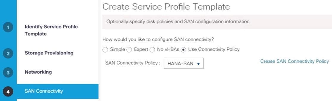
25. Zoning – Click Next.
26. vNIC/vHBA Placement for B480-M5:
![]() With the Cisco UCS B480 M5 Blade Server populated with VIC 1340 + Port expander recognized as Adapter1 and VIC 1380 as Adapter 3. Therefore, using vCONs 1 and 3 for the vNIC/vHBA assignment.
With the Cisco UCS B480 M5 Blade Server populated with VIC 1340 + Port expander recognized as Adapter1 and VIC 1380 as Adapter 3. Therefore, using vCONs 1 and 3 for the vNIC/vHBA assignment.
a. In the Select Placement list, choose the Specify Manually.
b. From the vHBAs tab, assign vhba-a to vCON1.
Figure 76 Service Profile Template – vNIC/vHBA Placement – vHBA Assignment to vCON1
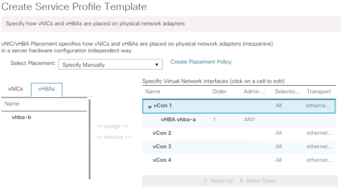
c. From the vNICs tab, choose vCon1 and assign the vNICs to the virtual network interfaces policy in the following order:
i. HANA-Client
ii. HANA-AppServer
iii. HANA-Replication
Figure 77 Service Profile Template – vNIC/vHBA Placement – vNIC Assignment to vCON1
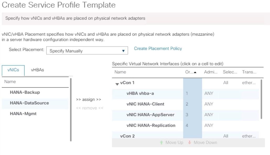
d. Select vCON3. From the vHBAs tab, assign vhba-b to vCON3
e. Choose vCon3 and assign the vNICs to the virtual network interfaces policy in the following order:
i. HANA-Backup
ii. HANA-DataSource
iii. HANA-Mgmt
Figure 78 Service Profile Template – vNIC/vHBA Placement – vNIC Assignment to vCON2
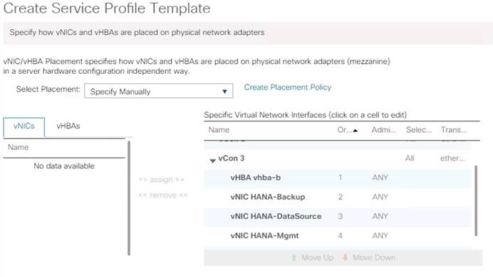
f. Review the table to verify that all vNICs are assigned to the policy in the appropriate order.
g. Click Next.
27. vNIC/vHBA Placement for B200-M5:
![]() With the Cisco UCS B200 M5 Blade Server populated with VIC 1340 + Port expander recognized as Adapter1. Therefore, using vCONs 1 only for the vNIC/vHBA assignment.
With the Cisco UCS B200 M5 Blade Server populated with VIC 1340 + Port expander recognized as Adapter1. Therefore, using vCONs 1 only for the vNIC/vHBA assignment.
a. In the Select Placement list, choose the Specify Manually.
b. From the vHBAs tab, assign vhba-a and vbha-b to vCON1
c. From the vNICs tab, choose vCon1 and assign the vNICs to the virtual network interfaces policy in the following order:
i. HANA-Client
ii. HANA-AppServer
iii. HANA-Replication
iv. HANA-Backup
v. HANA-DataSource
vi. HANA-Mgmt
d. Review the table to verify that all vNICs are assigned to the policy in the appropriate order.
f. Click Next.
28. No Change required on the vMedia Policy, click Next.
29. Set the server boot order:
a. Select HANA-SanBoot for Boot Policy.
Figure 79 Service Profile Template – Server Boot Order
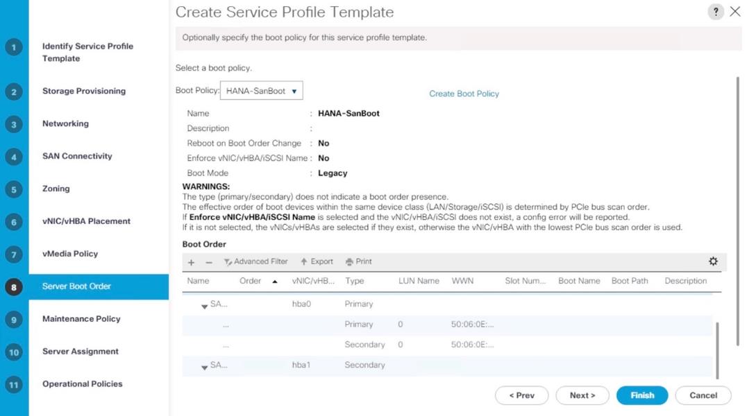
30. Click Next.
31. For Maintenance policy:
a. Select the ‘default’ Maintenance Policy. Click Next.
32. For Server Assignment: Expand Firmware Management at the bottom of the page and select HANA-FW from the Host Firmware list. Click Next.
Figure 80 Service Profile Template Server Assignment
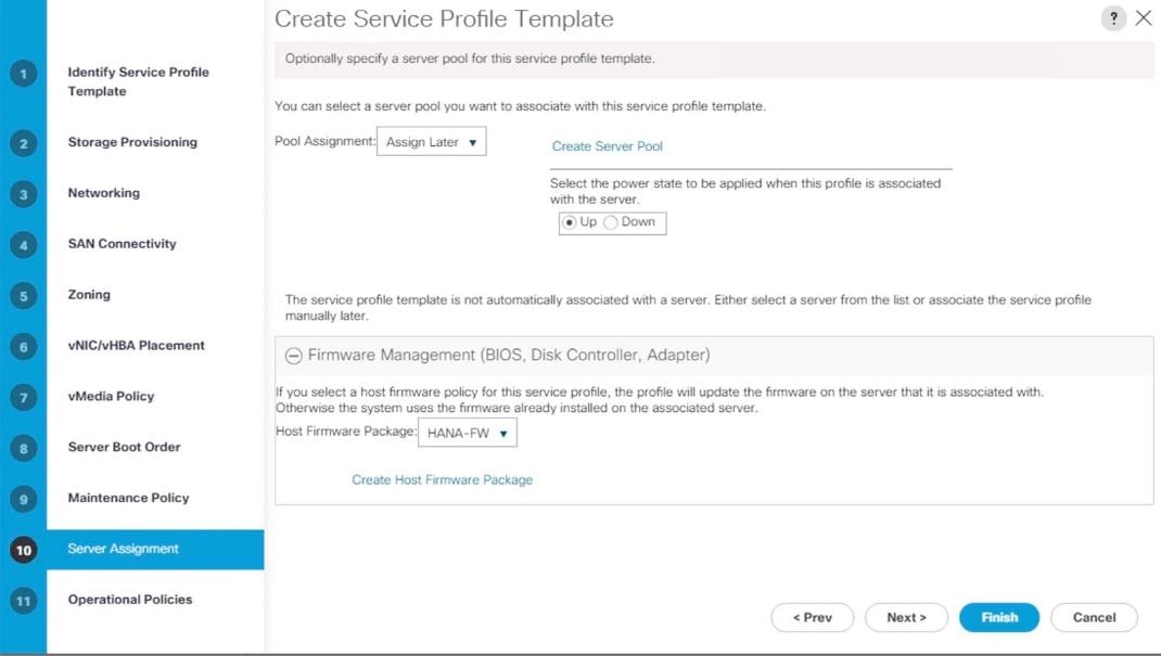
33. For Operational Policies:
a. BIOS Configuration - In the BIOS Policy list, select HANA-BIOS.
34. External IPMI Management Configuration - Expand the External IPMI Management Configuration. Select SoL-Console in the SoL Configuration Profile.
35. Management IP Address - In the Outband IPv4 tab choose ext-mgmt in the Management IP Address Policy.
36. Power Control Policy Configuration - Select HANA from the drop-down list.
37. Leave the Scrub policy, KVM Management Policy and Graphics Card Policy with default selections.
Figure 81 Service Profile Template Operational Policies
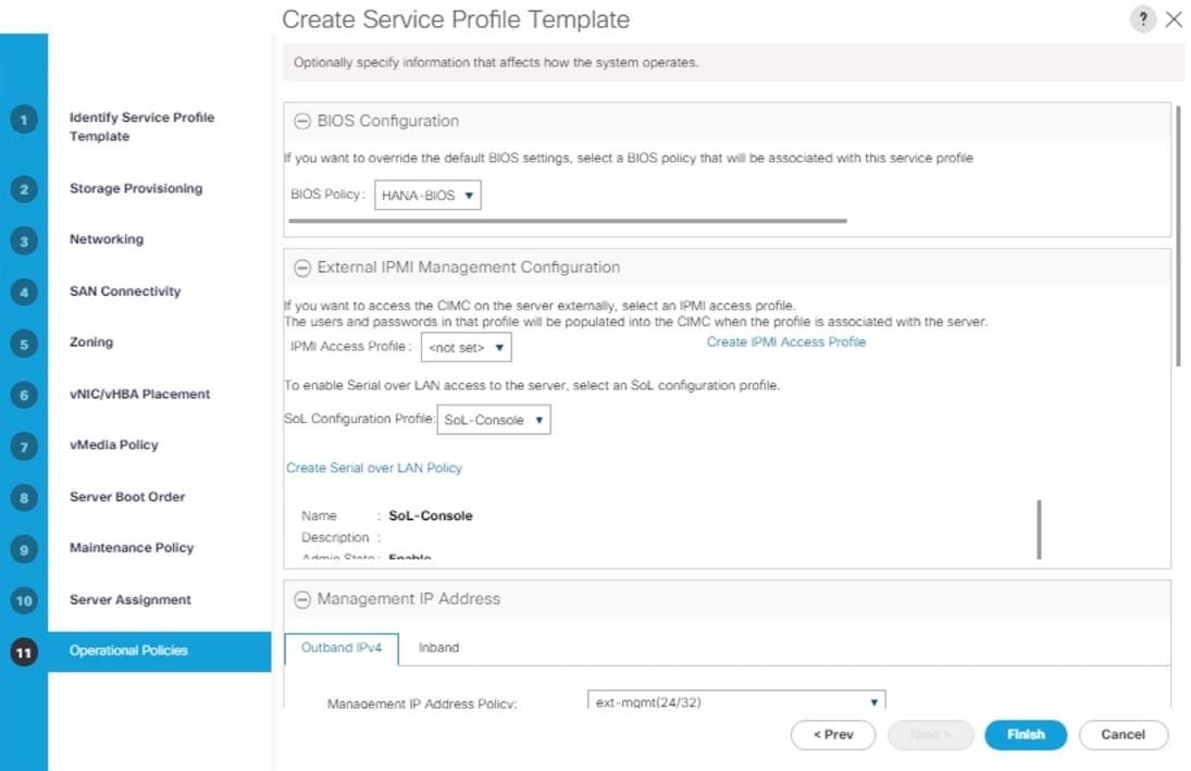
38. Click Finish to create the service profile template.
39. Click OK in the confirmation message.
Create Service Profile from the Template
To create service profiles from the service profile template, follow these steps:
1. In Cisco UCS Manager, click the Servers tab in the navigation pane.
2. Select Service Profile Templates > root > Sub-Organization > T01-HANA > Service Template HANA-ScaleUp.
3. Right-click Service Template HANA-ScaleUp and select Create Service Profiles from Template
4. Enter HANA-ScaleUp-0 as the service profile prefix.
5. Enter 1 as Name Suffix Starting Number.
6. Enter 4 as the Number of Instances
7. Click OK to create the service profile.
Figure 82 Creating Service Profiles from Template
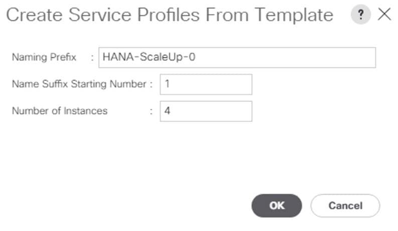
The MDS configuration implements a common redundant physical fabric design with fabrics represented as “A” and “B”. The validating lab provided a basic MDS fabric supporting VSP Storage Systems that is connected to UCS Fabric Interconnect within the SAN environment. Larger deployments may require a multi-tier core-edge or edge-core-edge design with port channels connecting the differing layers of the topology. Further discussion of these kinds of topologies, as well as considerations in implementing more complex SAN environments can be found in this white paper: https://www.cisco.com/c/en/us/products/collateral/storage-networking/mds-9700-series-multilayer-directors/white-paper-c11-729697.pdf
The configuration steps described below are implemented for the Cisco MDS 9706 but are similar to steps required for other Cisco MDS 9000 series switches that may be appropriate for a deployment. When making changes to the design that comply with the compatibility matrices of Cisco and Hitachi, it is required to consult the appropriate configuration documents of the differing equipment to confirm the correct implementation steps.
Physical Connectivity
Physical cabling should be completed by following the diagram and table references section Deployment Hardware and Software.
Cisco MDS Initial Configuration Dialogue
Complete this dialogue on each switch, using a serial connection to the console port of the switch, unless Power on Auto Provisioning is being used.
---- System Admin Account Setup ----
Do you want to enforce secure password standard (yes/no) [y]:
Enter the password for "admin": <<var_password>>
Confirm the password for "admin": <<var_password>>
---- Basic System Configuration Dialog ----
This setup utility will guide you through the basic configuration of
the system. Setup configures only enough connectivity for management
of the system.
Please register Cisco MDS 9000 Family devices promptly with your
supplier. Failure to register may affect response times for initial
service calls. MDS devices must be registered to receive entitled
support services.
Press Enter at anytime to skip a dialog. Use ctrl-c at anytime
to skip the remaining dialogs.
Would you like to enter the basic configuration dialog (yes/no): yes
Create another login account (yes/no) [n]: <enter>
Configure read-only SNMP community string (yes/no) [n]: <enter>
Configure read-write SNMP community string (yes/no) [n]: <enter>
Enter the switch name : <<var_mds_A_hostname>>|<<var_mds_B_hostname>>
Continue with Out-of-band (mgmt0) management configuration? (yes/no) [y]: <enter>
Mgmt0 IPv4 address : <<var_mds_A_mgmt_ip>>|<<var_mds_B_mgmt_ip>>
Mgmt0 IPv4 netmask : <<var_oob_netmask>>
Configure the default gateway? (yes/no) [y]: <enter>
IPv4 address of the default gateway : <<var_oob_gateway>>
Configure advanced IP options? (yes/no) [n]: <enter>
Enable the ssh service? (yes/no) [y]: <enter>
Type of ssh key you would like to generate (dsa/rsa) [rsa]: <enter>
Number of rsa key bits <1024-2048> [1024]: 2048
Enable the telnet service? (yes/no) [n]: y
Enter the type of drop to configure congestion/no_credit drop? (con/no) [c]: <enter>
Enter milliseconds in multiples of 10 for congestion-drop for logical-type edge
in range (<200-500>/default), where default is 500. [d]: <enter>
Congestion-drop for logical-type core must be greater than or equal to
Congestion-drop for logical-type edge. Hence, Congestion drop for
logical-type core will be set as default.
Enable the http-server? (yes/no) [y]: <enter>
Configure clock? (yes/no) [n]: y
Clock config format [HH:MM:SS Day Mon YYYY] [example: 18:00:00 1 november 2012]: <enter>
Enter clock config :17:26:00 2 january 2019
Configure timezone? (yes/no) [n]: y
Enter timezone config [PST/MST/CST/EST] :EST
Enter Hrs offset from UTC [-23:+23] : <enter>
Enter Minutes offset from UTC [0-59] : <enter>
Configure summertime? (yes/no) [n]: <enter>
Configure the ntp server? (yes/no) [n]: y
NTP server IPv4 address : <var_oob_ntp>
Configure default switchport interface state (shut/noshut) [shut]: noshut
Configure default switchport trunk mode (on/off/auto) [on]: auto
Configure default switchport port mode F (yes/no) [n]: y
Configure default zone policy (permit/deny) [deny]: <enter>
Enable full zoneset distribution? (yes/no) [n]: <enter>
Configure default zone mode (basic/enhanced) [basic]: <enter>
The following configuration will be applied:
password strength-check
switchname <<var_mds_A_hostname>>|<<var_mds_B_hostname>>
interface mgmt0
ip address <<var_mds_A_mgmt_ip>>|<<var_mds_B_mgmt_ip>> <<var_oob_netmask>>
no shutdown
ip default-gateway <<var_oob_gateway>>
ssh key rsa 2048 force
feature ssh
feature telnet
system timeout congestion-drop default logical-type edge
system timeout congestion-drop default logical-type core
feature http-server
clock set 13:51:00 6 january 2019
clock timezone PST 0 0
ntp server 192.168.93.16
no system default switchport shutdown
system default switchport trunk mode auto
system default switchport mode F
no system default zone default-zone permit
no system default zone distribute full
no system default zone mode enhanced
Would you like to edit the configuration? (yes/no) [n]: <enter>
Use this configuration and save it? (yes/no) [y]: <enter>
[########################################] 100%
Copy complete.
Cisco MDS Switch Configuration
Configure Fibre Channel Ports and Port Channels
To configure the fibre channel ports and port channels, follow these steps:
1. On MDS 9706 A enter the configuration mode and enable the required features as shown below:
feature fport-channel-trunk
feature npiv
2. Use the following commands to configure the FC Port channel and add all FC ports connected to Cisco UCS Fabric Interconnect A:
int port-channel <<var_fc-pc_a_id>>
channel mode active
int fc1/1-4
channel-group <<var_fc-pc_a_id>> force
int port-channel <<var_fc-pc_a_id>>
switchport mode F
switchport trunk mode off
no shut
3. On MDS 9706 B enter the configuration mode and enable the required features as shown below:
feature fport-channel-trunk
feature npiv
4. Use the following commands to configure the FC Port channel and add all FC ports connected to Cisco UCS Fabric Interconnect B:
int port channel <<var_fc-pc_b_id>>
channel mode active
int fc1/1-4
channel-group <<var_fc-pc_b_id>> force
int port channel <<var_fc-pc_b_id>>
switchport mode F
switchport trunk mode off
no shut
Configure VSANs
To configure VSANs, follow these steps:
1. On MDS 9706 A enter the configuration mode and execute the following commands to configure the VSAN:
vsan database
vsan <<var_san_a_id>>
vsan <<var_san_a_id>> interface port-channel <<var_fc-pc_a_id>>
vsan 10 interface fc 1/13
Traffic on fc1/13 may be impacted. Do you want to continue? (y/n) [n] y
vsan 10 interface fc 1/14
Traffic on fc1/14 may be impacted. Do you want to continue? (y/n) [n] y
vsan 10 interface fc 1/15
Traffic on fc1/15 may be impacted. Do you want to continue? (y/n) [n] y
vsan 10 interface fc 1/16
Traffic on fc1/16 may be impacted. Do you want to continue? (y/n) [n] y
int fc 1/13-16
switchport trunk mode off
switchport trunk allowed vsan <<var_san_a_id>>
Warning: This command will remove all VSANs currently being trunked and trunk only the specified VSANs.
Do you want to continue? (y/n) [n] y
no shut
2. On MDS 9706 B enter the configuration mode and execute the following commands to configure the VSAN:
vsan database
vsan <<var_san_b_id>>
vsan <<var_san_b_id>> interface port-channel <<var_fc-pc_b_id>>
vsan <<var_san_b_id>> interface fc 1/13
Traffic on fc1/13 may be impacted. Do you want to continue? (y/n) [n] y
vsan <<var_san_b_id>> interface fc 1/14
Traffic on fc1/14 may be impacted. Do you want to continue? (y/n) [n] y
vsan <<var_san_b_id>> interface fc 1/15
Traffic on fc1/15 may be impacted. Do you want to continue? (y/n) [n] y
vsan <<var_san_b_id>> interface fc 1/16
Traffic on fc1/16 may be impacted. Do you want to continue? (y/n) [n] y
int fc 1/13-16
switchport trunk mode off
switchport trunk allowed vsan <<var_san_b_id>>
Warning: This command will remove all VSANs currently being trunked and trunk only the specified VSANs.
Do you want to continue? (y/n) [n] y
no shut
![]() Make sure to save the configuration to the startup config using the command “copy running-config startup-config”
Make sure to save the configuration to the startup config using the command “copy running-config startup-config”
Create and Configure Fiber Channel Zoning
To create the Fiber Channel connections between the Cisco MDS 9706 switches, the Cisco UCS Fabric Interconnects, and the Hitachi Storage, follow these steps:
1. Log into the Cisco UCS Manager > Servers > Service Profiles > root > Sub-Organizations >T01-HANA > Service Profile HANA–ScaleUp-01. On the right-hand pane, click the Storage tab and vHBA's tab to get the WWPN of HBA's as shown in the figure below.
Figure 83 WWPN of a Server Node
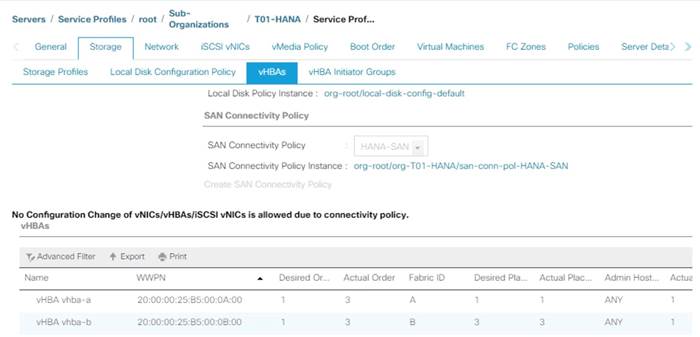
2. Note the WWPN of the all the configured Servers from their Service Profiles.
In the current example configuration, the WWPN numbers of four server nodes configured are 20:00:00:25:B5:0A:00:00 - 20:00:00:25:B5:0A:00:03 for the Fabric A and 20:00:00:25:B5:0B:00:00 - 20:00:00:25:B5:0B:00:03
3. Connect to the Hitachi Storage and extract the WWPN of FC Ports connected to the Cisco MDS Switches. We have connected 8 FC ports from Hitachi Storage to Cisco MDS Switches. FC ports CL1-A, CL1-B, CL2-A, CL2-B are connected to MDS Switch-A and similarly FC ports CL3-A, CL3-B, CL3-A, CL3-B are connected to MDS Switch-B.
Figure 84 WWPN of Hitachi Storage
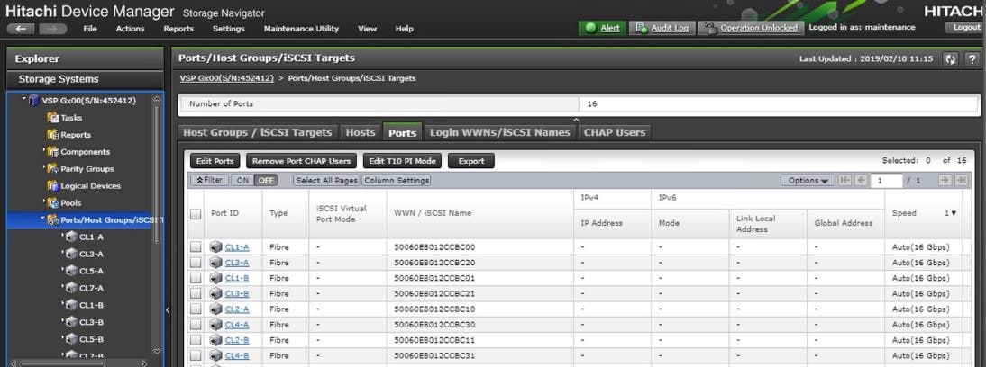
Create Device Aliases for Fibre Channel Zoning
To configure device aliases and zones for the primary boot paths of MDS switch A, follow this step:
1. Login as admin user and run the following commands.
conf t
device-alias database
device-alias name G370-Cntrl-1-CL1A pwwn 50:06:0e:80:12:cc:bc:00
device-alias name G370-Cntrl-1-CL1B pwwn 50:06:0e:80:12:cc:bc:01
device-alias name G370-Cntrl-1-CL2A pwwn 50:06:0e:80:12:cc:bc:10
device-alias name G370-Cntrl-1-CL2B pwwn 50:06:0e:80:12:cc:bc:11
device-alias name HANA-Server01-hba-a pwwn 20:00:00:25:b5:00:0a:00
device-alias name HANA-Server02-hba-a pwwn 20:00:00:25:b5:00:0a:01
device-alias name HANA-Server03-hba-a pwwn 20:00:00:25:b5:00:0a:02
device-alias name HANA-Server04-hba-a pwwn 20:00:00:25:b5:00:0a:03
exit
device-alias commit
To configure device aliases and zones for the primary boot paths of MDS switch B, follow this step:
1. Login as admin user and run the following commands.
conf t
device-alias database
device-alias name G370-Cntrl-2-CL3A pwwn 50:06:0e:80:12:cc:bc:20
device-alias name G370-Cntrl-2-CL3B pwwn 50:06:0e:80:12:cc:bc:21
device-alias name G370-Cntrl-2-CL4A pwwn 50:06:0e:80:12:cc:bc:30
device-alias name G370-Cntrl-2-CL4B pwwn 50:06:0e:80:12:cc:bc:31
device-alias name HANA-Server01-hba-b pwwn 20:00:00:25:b5:00:0b:00
device-alias name HANA-Server02-hba-b pwwn 20:00:00:25:b5:00:0b:01
device-alias name HANA-Server03-hba-b pwwn 20:00:00:25:b5:00:0b:02
device-alias name HANA-Server04-hba-b pwwn 20:00:00:25:b5:00:0b:03
exit
device-alias commit
Create Zoning
To configure zones for the MDS switch A, follow these steps:
1. Create a zone for each service profile.
2. Login as admin user and run the following commands.
conf t
zone name HANA-Server01-A vsan 10
member device-alias G370-Cntrl-1-CL1A
member device-alias G370-Cntrl-1-CL1B
member device-alias G370-Cntrl-1-CL2A
member device-alias G370-Cntrl-1-CL2B
member device-alias HANA-Server01-hba-a
exit
zone name HANA-Server02-A vsan 10
member device-alias G370-Cntrl-1-CL1A
member device-alias G370-Cntrl-1-CL1B
member device-alias G370-Cntrl-1-CL2A
member device-alias G370-Cntrl-1-CL2B
member device-alias HANA-Server02-hba-a
exit
zone name HANA-Server03-A vsan 10
member device-alias G370-Cntrl-1-CL1A
member device-alias G370-Cntrl-1-CL1B
member device-alias G370-Cntrl-1-CL2A
member device-alias G370-Cntrl-1-CL2B
member device-alias HANA-Server03-hba-a
exit
zone name HANA-Server04-A vsan 10
member device-alias G370-Cntrl-1-CL1A
member device-alias G370-Cntrl-1-CL1B
member device-alias G370-Cntrl-1-CL2A
member device-alias G370-Cntrl-1-CL2B
member device-alias HANA-Server04-hba-a
exit
3. After the zone for the Cisco UCS service profile has been created, create the zone set and add the necessary members.
zoneset name HANA-Servers-A vsan 10
member HANA-Server01-A
member HANA-Server02-A
member HANA-Server03-A
member HANA-Server04-A
exit
4. Activate the zone set by running following commands.
zoneset activate name HANA-Servers-A vsan 10
exit
copy run start
To configure zones for the MDS switch B, follow these steps:
1. Create a zone for each service profile.
2. Login as admin user and run the following commands.
conf t
zone name HANA-Server01-B vsan 20
member device-alias G370-Cntrl-2-CL3A
member device-alias G370-Cntrl-2-CL3B
member device-alias G370-Cntrl-2-CL4A
member device-alias G370-Cntrl-2-CL4B
member device-alias HANA-Server01-hba-b
exit
zone name HANA-Server02-B vsan 20
member device-alias G370-Cntrl-2-CL3A
member device-alias G370-Cntrl-2-CL3B
member device-alias G370-Cntrl-2-CL4A
member device-alias G370-Cntrl-2-CL4B
member device-alias HANA-Server02-hba-b
exit
zone name HANA-Server03-B vsan 20
member device-alias G370-Cntrl-2-CL3A
member device-alias G370-Cntrl-2-CL3B
member device-alias G370-Cntrl-2-CL4A
member device-alias G370-Cntrl-2-CL4B
member device-alias HANA-Server03-hba-b
exit
zone name HANA-Server04-B vsan 20
member device-alias G370-Cntrl-2-CL3A
member device-alias G370-Cntrl-2-CL3B
member device-alias G370-Cntrl-2-CL4A
member device-alias G370-Cntrl-2-CL4B
member device-alias HANA-Server04-hba-b
exit
3. After the zone for the Cisco UCS service profile has been created, create the zone set and add the necessary members.
zoneset name HANA-Servers-B vsan 20
member HANA-Server01-B
member HANA-Server02-B
member HANA-Server03-B
member HANA-Server04-B
exit
4. Activate the zone set by running following commands.
zoneset activate name HANA-Servers-B vsan 20
exit
copy run start
This section provides the procedure for Operating System installation using SAN Boot and operating system customizing for SAP HANA requirement.
Associate Service Profile to Cisco UCS Server
To associate service profile created for a specific server, follow these steps:
1. In Cisco UCS Manager, click the Servers tab in the navigation pane.
2. Select Service Profile > root > Sub-Organization > T01-HANA > HANA-ScaleUp-01.
3. Right-click HANA-ScaleUp-01 and select Change Service Profile Association.
4. For Server Assignment, select the existing Server from the drop-down list.
5. Click Available Servers.
6. Select the server, as required. Click OK. Click Yes for the Warning. Click OK.
Figure 85 Creating Service Profiles from Template
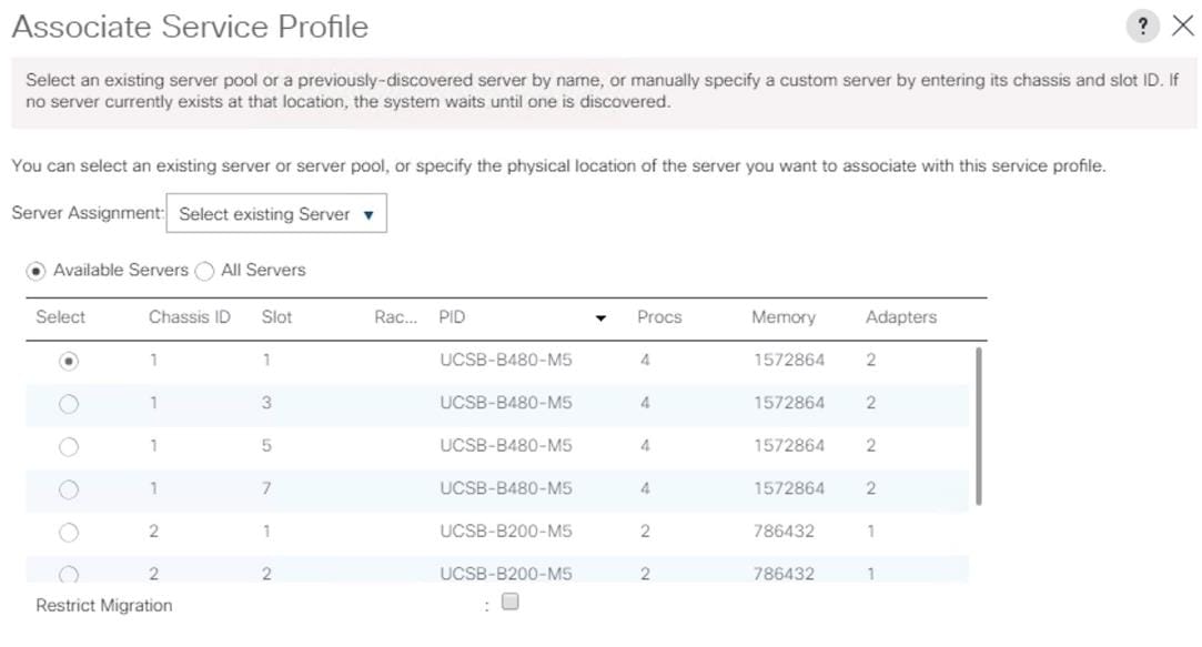
7. Repeat steps 1-6 to associate each Service Profile with a Server.
SLES for SAP 12 SP4 OS Installation
This section provides the procedure for SUSE Linux Enterprise Server for SAP Applications 12 SP 4 Operating System and customizing for SAP HANA requirement.
![]() The following procedure requires SLES for SAP 12 SP 4 installation ISO image.
The following procedure requires SLES for SAP 12 SP 4 installation ISO image.
To install the SLES for SAP 12 SP4, follow these steps:
1. In Cisco UCS Manager, click the Servers tab in the navigation pane.
2. Select Service Profile > root > Sub-Organization > T01-HANA > HANA-ScaleUp-01.
3. Click KVM Console.
4. When the KVM Console is launched, click Boot Server.
5. Choose Virtual Media > Activate Virtual Devices.
a. For Unencrypted Virtual Media Session, select Accept this Session and then click Apply.
6. Click Virtual Media and choose Map CD/DVD.
7. Click Browse to navigate to the ISO media location. Select SLE-12-SP4-SAP-DVD-x86_64-GM-DVD1.ISO Click Open.
8. Click Map Device.
9. At server boot time, during verification of VIC FC boot driver version, it recognizes the Hitachi Storage by its target WWPN numbers. This verifies the server to storage connectivity.
Figure 86 Cisco VIC Boot Driver Recognizes Hitachi Storage

10. The System will automatically boot from the ISO image. Select the Installation option.
Figure 87 Booting to ISO image
11. On the first “Language, Keyboard and License Agreement” page, select the Language of choice and Keyboard Layout, “I Agree to license terms” and click Next.
12. On the Network Settings screen Under Overview, click VNIC Ethernet NIC.
a. To configure the network interface on the OS, it is required to identify the mapping of the Ethernet device on the OS to vNIC interface on the Cisco UCS.
b. In Cisco UCS Manager, click the Servers tab in the navigation pane.
c. Select Service Profile > root > Sub-Organization > T01-HANA > HANA-ScaleUp-01.
d. On the main pane click on Network, list of the vNICs with MAC Address are listed.
e. Note that the MAC Address of the HANA-Mgmt vNIC is “00:25:B5:00:0A:02”
Figure 88 Cisco UCS vNIC MAC Address
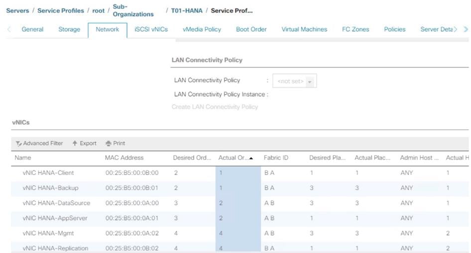
f. By comparing MAC Address on the OS and Cisco UCS, eth0 on OS will carry the VLAN for Management.
13. Click Edit, under the Address tab.
a. Click Statically Assigned IP Address:
b. In the IP Address field enter <<Management IP address>>.
c. In the Subnet Mask field enter <<subnet mask for Management Interface>>.
d. In the Hostname field enter the hostname for Management Interface.
Figure 89 Network Settings
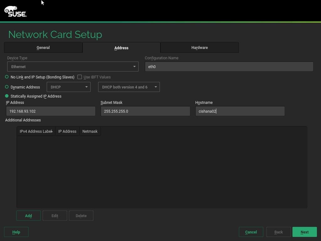
14. Repeat steps 12 and 13 for each vNIC. Alternatively, IP address for vNICs can be set post installation, by using ssh to connect to the server on Management IP.
15. On the Network Settings screen Select Hostname/DNS:
a. In the Hostname field enter the Hostname.
b. In the Domain Name Field enter the Domain Name.
c. In the Name Server 1 field enter <<DNS server1>> and Name Server 2 field enter <<DNS server2>>
d. In the Search domains field enter <<domain1.com,domain2.com>>.
Figure 90 Network Settings Hostname

16. Click Routing.
17. For the Default IPv4 Gateway enter the <<Default Gateway for>>.
Figure 91 Network Settings Routing
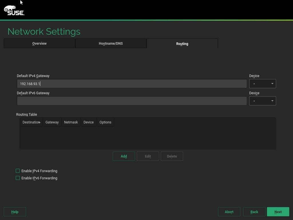
18. Click Next
19. System Probing – Select ‘No’ for the pop-up for Do you want to activate multipath?
Figure 92 System Probing – Multipath Activation Choice
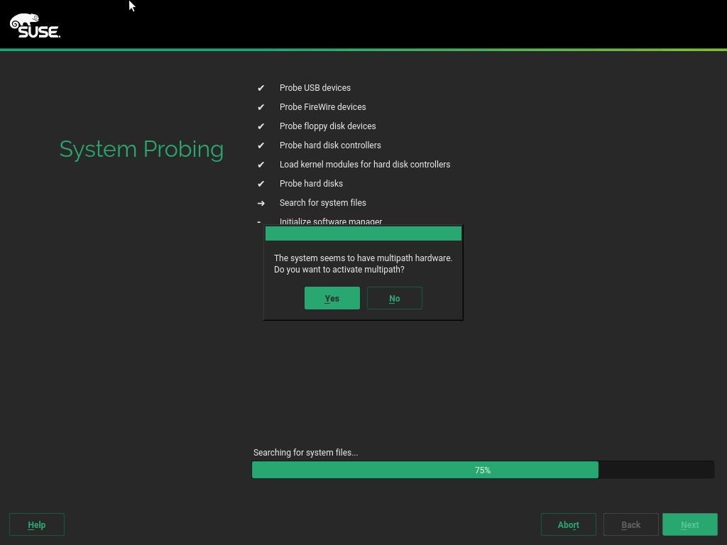
20. Registration – Select Skip Registration. We will do this later as part of post-installation tasks. Click ‘Yes’ for the confirmation warning pop-up to proceed.
21. Choose Operation System Edition – Select “SUSE Linux Enterprise Server for SAP Applications” option.
Figure 93 Choosing OS Edition
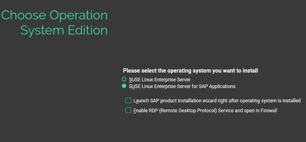
22. Add On Product: Click Next.
23. On Suggested Partitioning select Expert Partitioner.
Figure 94 Suggested Partitioning Initial Proposal -Example
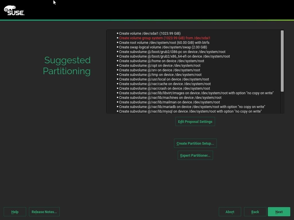
24. On the left ‘System View’ > <<hostname>> > Hard Disks > Select a device from the list which is 100G. In the navigation pane click Delete if found with the suggested partitions which results in an Unpartitioned disk of 100GB.
Figure 95 Expert Partitioner – Choose 100G Hard Disk Device
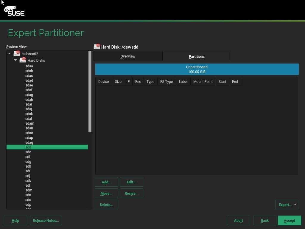
25. On the right pane, under Partitions tab, add a new Partition by selecting Add under the Partitions tab for the device. Select Primary Partition for New Partition Type in the next step.
Figure 96 Expert Partitioner – Add Primary Partition on /dev/ device
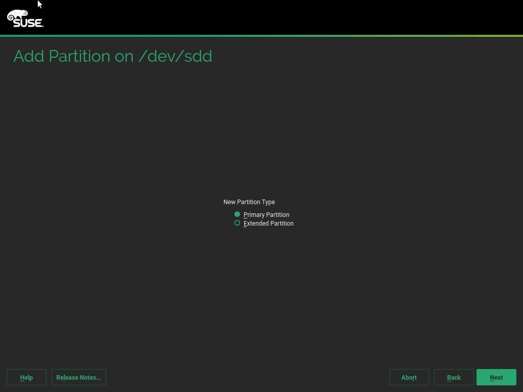
26. Select Maximum Size. Click Next.
Figure 97 Add Partition – Specify New Partition Size
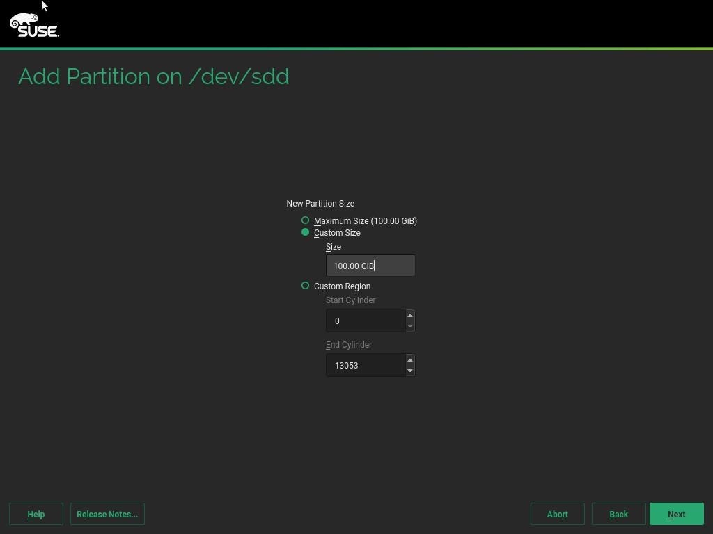
27. Click Next.
28. Select Operating System Role and click Next.
Figure 98 Add Partition – Specify Role
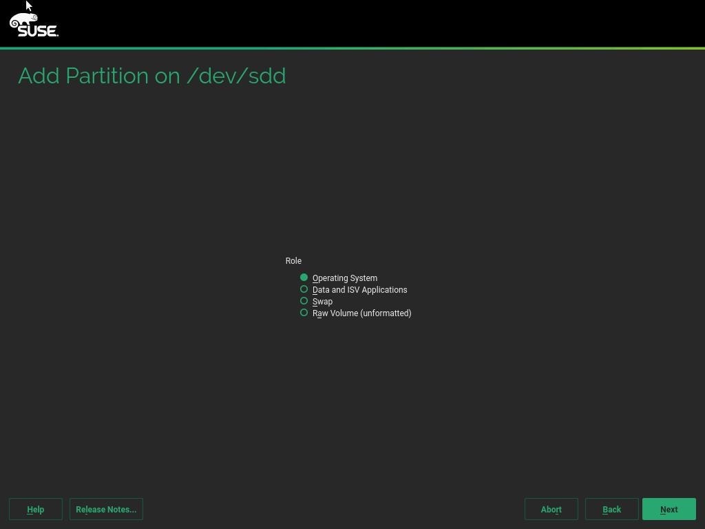
29. Select ext3 File system and / or Mount Point. Click Finish.
Figure 99 Add Partition- Formatting and Mounting Options
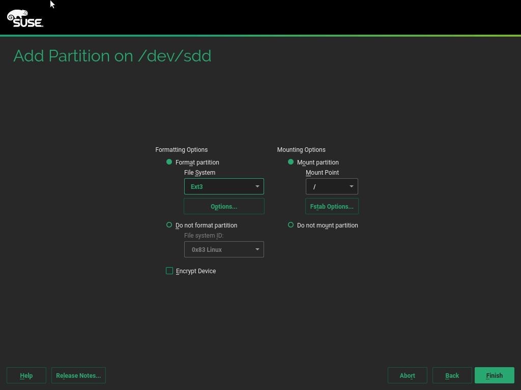
30. Click Accept to come back to the Installation Settings page.
Figure 100 Expert Partitioner – Summary
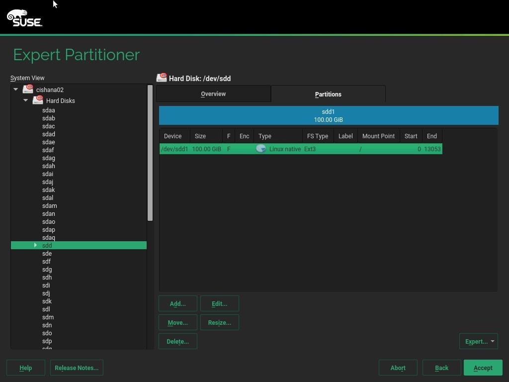
31. Click Yes to continue setup without swap partition. Click Accept.
32. Click Next on the final Suggested Partition page.
33. Clock and Time Zone – choose the appropriate time zone and select Hardware clock set to UTC.
34. Password for the System Administrator “root” – Key in appropriate password <<var_sys_root-pw>>
35. On the Installation Settings screen.
Figure 101 Installation Settings – Default Proposal
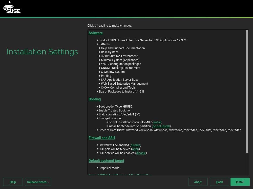
36. Customize the software selection. Click Software headline to make the following changes:
a. Deselect GNOME DE and X Window System.
a. Make sure C/C++ Compiler and Tools is selected.
b. Select SAP HANA Server Base.
c. Deselect SAP Application Sever Base.
Figure 102 Software Selection and System Tasks - Customized
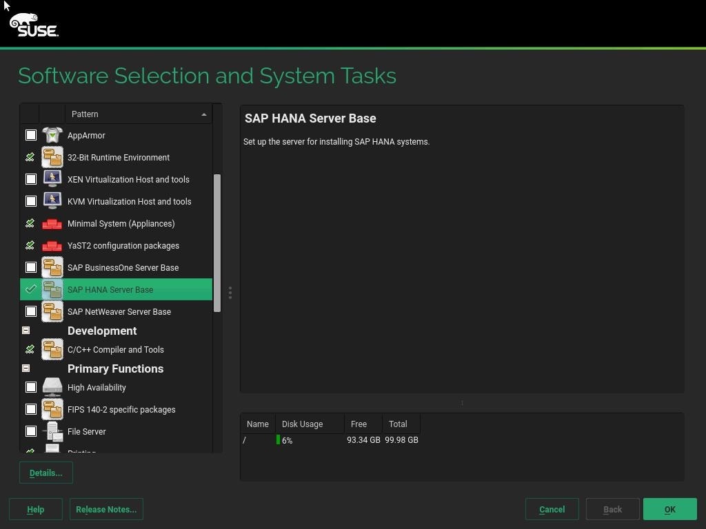
37. Click OK.
38. Under the Firewall and SSH headline, click ‘disable’ for Firewall. This will automatically enable SSH service.
Figure 103 Firewall and SSH - Customized
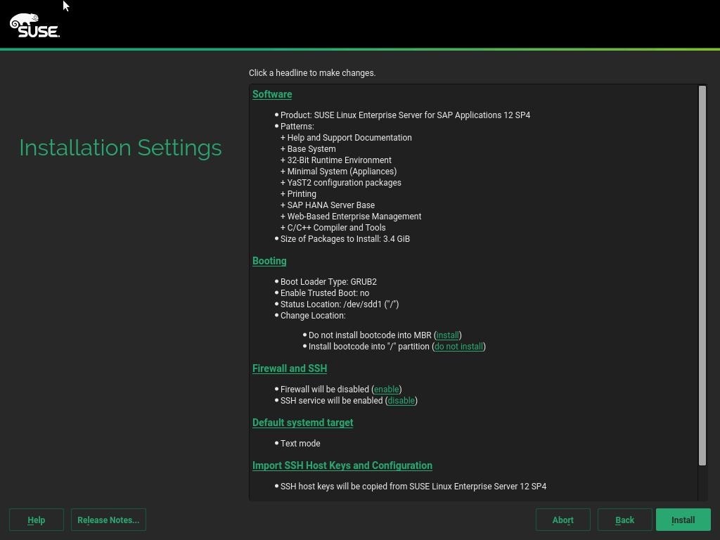
39. Leave the default selections unchanged.
Figure 104 Installation Settings – Final Selections
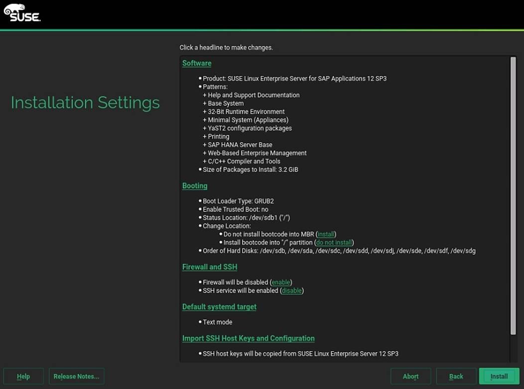
40. Click Install and select Install again for the subsequent ‘Confirm Installation’ prompt. The installation is started, and you can monitor the status.
Figure 105 Perform Installation
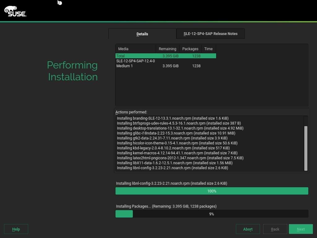
41. After the Operating System is installed the system will reboot.
Figure 106 Booting from Hard Disk
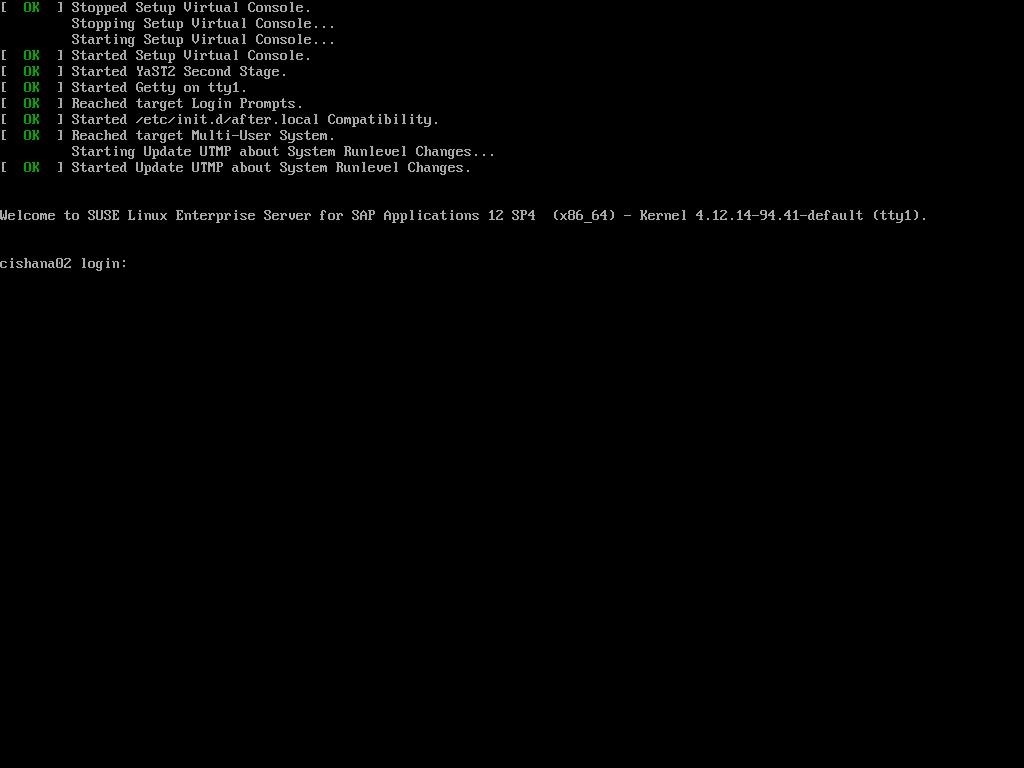
Network Services Configuration
To configure the server with Network services, follow these steps:
Hostnames
The operating system must be configured such a way that the short name of the server is displayed for the command ‘hostname’ and Full Qualified Host Name is displayed with the command ‘hostname –d’.
1. ssh to the Server using Management IP address assigned to the server during installation.
2. Login as root and password.
3. Set the hostname using hostnamectl
hostnamectl set-hostname <<hostname>>
IP Address
Each SAP HANA Server is configured with 6 vNIC device. Table 21 lists the IP Address information required to configure the IP address on the Operating System.
![]() The IP Address and Subnet Mask provided below are examples only, please configure the IP address for your environment.
The IP Address and Subnet Mask provided below are examples only, please configure the IP address for your environment.
Table 21 List the IP Address for SAP HANA Server
| vNIC Name |
VLAN ID |
IP Address Range |
Subnet Mask |
| HANA-AppServer |
<<var_appserver_vlan_id>> |
192.168.223.101 |
255.255.255.0 |
| HANA-Backup |
<<var_backup_vlan_id>> |
192.168.221.101 |
255.255.255.0 |
| HANA-Client |
<<var_client_vlan_id>> |
192.168.222.101 |
255.255.0.0 |
| HANA-DataSource |
<<var_datasource_vlan_id>> |
192.168.224.101 |
255.255.255.0 |
| HANA-Replication |
<<var_replication_vlan_id>> |
192.168.225.101 |
255.255.255.0 |
| Management |
<<var_mgmt_vlan_id>> |
192.168.93.101 |
255.255.0.0 |
1. To configure the network interface on the OS, it is required to identify the mapping of the ethernet device on the OS to vNIC interface on the Cisco UCS.
2. From the OS execute the below command to get list of Ethernet device with MAC Address.
ifconfig -a |grep HWaddr
eth0 Link encap:Ethernet HWaddr 00:25:B5:00:0A:02
eth1 Link encap:Ethernet HWaddr 00:25:B5:00:0B:01
eth2 Link encap:Ethernet HWaddr 00:25:B5:00:0A:00
eth3 Link encap:Ethernet HWaddr 00:25:B5:00:0A:01
eth4 Link encap:Ethernet HWaddr 00:25:B5:00:0B:02
eth5 Link encap:Ethernet HWaddr 00:25:B5:00:0B:00
3. In Cisco UCS Manager, click the Servers tab in the navigation pane.
4. Select Service Profile > root > Sub-Organization > T01-HANA > HANA-ScaleUp-01.
5. On the main pane, click Network; the list of the vNICs with MAC Address are listed.
Figure 107 Cisco UCS vNIC MAC Address
6. Note the MAC Address of the HANA-Client vNIC is “00:25:B5:00:0B:00”.
7. By comparing MAC Address on the OS and Cisco UCS, eth5 on OS will carry the VLAN for HANA-Client.
8. Go to network configuration directory and create a configuration for eth5
vi ifcfg-eth5
BOOTPROTO='static'
BROADCAST=''
ETHTOOL_OPTIONS=''
IPADDR='<<IP subnet for HANA-Client/subnet mask example:192.168.221.101/24>>
MTU='9000'
NAME='VIC Ethernet NIC'
NETWORK=''
REMOTE_IPADDR=''
STARTMODE='auto'
9. Repeat the steps 9 to 11 for each vNIC interface.
10. Add default gateway.
vi etc/sysconfig/network/routes
default 192.168.93.1 - -
DNS
Domain Name Service configuration must be done based on the local requirements.
1. Add DNS Servers entry:
vi /etc/resolv.conf
nameserver <<IP of DNS Server1>>
nameserver <<IP of DNS Server2>>
search <<Domain_name>>
Hosts file
HANA nodes should be able to resolve internal network IP address, below is an example of Scale Up HANA System host file with the entire network defined in the /etc/hosts file.
127.0.0.1 localhost
# special IPv6 addresses
::1 localhost ipv6-localhost ipv6-loopback
192.168.93.101 cishana01m.ciscolab.local cishana01m
192.168.222.101 cishana01c.ciscolab.local cishana01c
192.168.223.101 cishana01.ciscolab.local cishana01
192.168.224.101 cishana01d.ciscolab.local cishana01d
192.168.225.101 cishana01r.ciscolab.local cishana01r
192.168.221.101 cishana01b.ciscolab.local cishana01b
Network Time
It is important that the time on all components used for SAP HANA is in sync. The configuration of NTP is important and to be performed on all systems.
1. Configure NTP by adding at least one NTP server to the NTP config file /etc/ntp.conf.
vi /etc/ntp.conf
server <<var_oob_ntp>>
fudge <<var_oob_ntp>> stratum 10
keys /etc/ntp.keys
trustedkey 1
SLES for SAP 12 SP 4 System Update and OS Customization
To updated and customize the SLES 12 SP 4 System for HANA Servers, follow these steps:
1. Register SUSE Linux Enterprise installations with the SUSE Customer Center:
SUSEConnect -r <<Registration Code>> -e <<email address>>
![]() If proxy server is required to access the internet, please update the proxy settings at /etc/sysconfig/proxy
If proxy server is required to access the internet, please update the proxy settings at /etc/sysconfig/proxy
2. Execute the below command to update the SLES4SAP 12 SP 4 to latest patch level.
zypper update
3. Follow the on-screen instruction to complete the update process.
4. Disable transparent hugepages, Configure C-States for lower latency in Linux, Auto NUMA settings. Modify /etc/default/grub search for the line starting with "GRUB_CMDLINE_LINUX_DEFAULT" and append to this line:
numa_balancing=disable transparent_hugepage=never intel_idle.max_cstate=1 processor.max_cstate=1
5. Save your changes and run:
grub2-mkconfig -o /boot/grub2/grub.cfg
6. Add the following line into /etc/init.d/boot.local, for CPU Frequency, Energy Performance Bias, Kernel samepage merging settings:
cpupower set -b 0
cpupower frequency-set -g performance
echo 0 > /sys/kernel/mm/ksm/run
7. Activate tuned:
saptune daemon start
8. Enable tuned profile:
saptune solution apply HANA
9. Reboot the OS by issuing reboot command.
![]() The Operating System Installation and configurations documented in this CVD are from SAP Notes at the time of publication, for latest setting please follow the SAP Notes in the References section
The Operating System Installation and configurations documented in this CVD are from SAP Notes at the time of publication, for latest setting please follow the SAP Notes in the References section
Install Cisco eNIC and fNIC Driver
To download the Cisco UCS Drivers ISO bundle, which contains most of the Cisco UCS Virtual Interface Card drivers, follow these steps:
1. In a web browser, navigate to https://software.cisco.com/download/home/283853163/type/283853158/release/suse
![]() You must be signed in to download Cisco Unified Computing System (UCS) drivers.
You must be signed in to download Cisco Unified Computing System (UCS) drivers.
2. After the download is complete browse to:
a. cisco-ucs-drivers-1.1901.1.0-suse.iso\12.4\network\cisco\vic\3.1.142.369 and copy cisco-enic-usnic-kmp-default-3.1.142.369_k4.12.14_94.41-700.19.x86_64.rpm to HANA server
b. cisco-ucs-drivers-1.1901.1.0-suse.iso\12.4\storage\cisco\vic\1.6.0.47 and copy cisco-fnic-kmp-default-1.6.0.47_k4.12.14_94.37-1.x86_64.rpm to HANA server
3. ssh to the Server as root.
4. Update the enic driver with below command:
rpm -Uvh cisco-enic-usnic-kmp-default-3.1.142.369_k4.12.14_94.41-700.19.x86_64.rpm
5. Update the fnic driver with below command:
rpm -Uvh cisco-fnic-kmp-default-1.6.0.47_k4.12.14_94.37-1.x86_64.rpm
Multipath Configuration
This reference architecture uses Device-mapper Multipath, a native component of the Linux operating system. Using Device-mapper Multipath allows the configuration of multiple I/O paths between the server blades and storages.
Each node has two I/O paths connected with the storage. Multipathing aggregates all physical I/O paths into a single logical path. The LUNs are always available unless both paths fail.
Device-mapper Multipath is used for the following I/O paths:
· SAP HANA server boot volume
· SAP HANA data volume
· SAP HANA log volume
· SAP HANA shared volume
1. ssh to the Server as root.
2. Create the following entry in /etc/multipath.conf
vi /etc/multipath.conf
blacklist {
devnode "^(ram|raw|loop|fd|md|dm-|sr|scd|st)[0-9]*"
devnode "^hd[a-z]"
devnode "^dcssblk[0-9]*"
}
devices {
device {
vendor "HITACHI"
product ".*"
user_friendly_names no
path_checker directio
path_grouping_policy multibus
path_selector "queue-length 0"
uid_attribute ID_SERIAL
failback immediate
rr_weight uniform
rr_min_io_rq 128
features 0
no_path_retry 5
}
}
3. Start the multipath daemon and enable to start at the boot
systemctl start multipathd
systemctl enable multipathd
4. Check the status of multipath devices using multipath -ll
multipath -ll
360060e8012ccbc005040ccbc00000033 dm-8 HITACHI,OPEN-V
size=384G features='1 queue_if_no_path' hwhandler='0' wp=rw
`-+- policy='queue-length 0' prio=1 status=active
|- 0:0:0:9 sdad 65:208 active ready running
|- 0:0:1:9 sdan 66:112 active ready running
|- 6:0:0:9 sdj 8:144 active ready running
`- 6:0:1:9 sdt 65:48 active ready running
360060e8012ccbc005040ccbc00000032 dm-7 HITACHI,OPEN-V
size=384G features='1 queue_if_no_path' hwhandler='0' wp=rw
`-+- policy='queue-length 0' prio=1 status=active
|- 0:0:0:8 sdac 65:192 active ready running
|- 0:0:1:8 sdam 66:96 active ready running
|- 6:0:0:8 sdi 8:128 active ready running
`- 6:0:1:8 sds 65:32 active ready running
360060e8012ccbc005040ccbc00000029 dm-0 HITACHI,OPEN-V
size=1.0T features='1 queue_if_no_path' hwhandler='0' wp=rw
`-+- policy='queue-length 0' prio=1 status=active
|- 0:0:0:1 sdv 65:80 active ready running
|- 0:0:1:1 sdaf 65:240 active ready running
|- 6:0:0:1 sdb 8:16 active ready running
`- 6:0:1:1 sdl 8:176 active ready running
360060e8012ccbc005040ccbc00000031 dm-6 HITACHI,OPEN-V
size=384G features='1 queue_if_no_path' hwhandler='0' wp=rw
`-+- policy='queue-length 0' prio=1 status=active
|- 0:0:0:7 sdab 65:176 active ready running
|- 0:0:1:7 sdal 66:80 active ready running
|- 6:0:0:7 sdh 8:112 active ready running
`- 6:0:1:7 sdr 65:16 active ready running
360060e8012ccbc005040ccbc00000030 dm-5 HITACHI,OPEN-V
size=384G features='1 queue_if_no_path' hwhandler='0' wp=rw
`-+- policy='queue-length 0' prio=1 status=active
|- 0:0:0:6 sdaa 65:160 active ready running
|- 0:0:1:6 sdak 66:64 active ready running
|- 6:0:0:6 sdg 8:96 active ready running
`- 6:0:1:6 sdq 65:0 active ready running
360060e8012ccbc005040ccbc0000001b dm-4 HITACHI,OPEN-V
size=128G features='1 queue_if_no_path' hwhandler='0' wp=rw
`-+- policy='queue-length 0' prio=1 status=active
|- 0:0:0:5 sdz 65:144 active ready running
|- 0:0:1:5 sdaj 66:48 active ready running
|- 6:0:0:5 sdf 8:80 active ready running
`- 6:0:1:5 sdp 8:240 active ready running
360060e8012ccbc005040ccbc0000001a dm-3 HITACHI,OPEN-V
size=128G features='1 queue_if_no_path' hwhandler='0' wp=rw
`-+- policy='queue-length 0' prio=1 status=active
|- 0:0:0:4 sdy 65:128 active ready running
|- 0:0:1:4 sdai 66:32 active ready running
|- 6:0:0:4 sde 8:64 active ready running
`- 6:0:1:4 sdo 8:224 active ready running
360060e8012ccbc005040ccbc00000019 dm-2 HITACHI,OPEN-V
size=128G features='1 queue_if_no_path' hwhandler='0' wp=rw
`-+- policy='queue-length 0' prio=1 status=active
|- 0:0:0:3 sdx 65:112 active ready running
|- 0:0:1:3 sdah 66:16 active ready running
|- 6:0:0:3 sdd 8:48 active ready running
`- 6:0:1:3 sdn 8:208 active ready running
360060e8012ccbc005040ccbc00000018 dm-1 HITACHI,OPEN-V
size=128G features='1 queue_if_no_path' hwhandler='0' wp=rw
`-+- policy='queue-length 0' prio=1 status=active
|- 0:0:0:2 sdw 65:96 active ready running
|- 0:0:1:2 sdag 66:0 active ready running
|- 6:0:0:2 sdc 8:32 active ready running
`- 6:0:1:2 sdm 8:192 active ready running
5. Use dracut to include multipath in the initrd image:
dracut --force --add multipath
Red Hat Enterprise Linux for SAP Solutions 7.5 OS Installation
This section provides the procedure for RedHat Enterprise Linux 7.5 Operating System and customizing for SAP HANA requirement.
![]() The following procedure requires RHEL 7.5 installation ISO image.
The following procedure requires RHEL 7.5 installation ISO image.
To install the RHEL 7.5 system, follow these steps:
1. In Cisco UCS Manager, click the Servers tab in the navigation pane.
2. Select Service Profile > root > Sub-Organization > T01-HANA > HANA-ScaleUp-03.
3. Click KVM Console.
4. When the KVM Console is launched, click Boot Server.
5. Choose Virtual Media > Activate Virtual Devices:
a. For Unencrypted Virtual Media Session, select Accept this Session and then click Apply.
6. Click Virtual Media and choose Map CD/DVD.
7. Click Browse to navigate to the ISO media location. Select rhel-server-7.5-x86_64-dvd.iso Click Open.
8. Click Map Device.
9. At server boot time, during verification of VIC FC boot driver version, it recognizes the Hitachi Storage by its target WWPN numbers. This verifies the server to storage connectivity.
Figure 108 Cisco VIC Boot Driver recognize Hitachi Storage
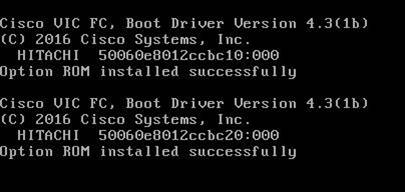
10. On the Initial screen choose Install Red Hat Enterprise Linux 7.5 to begin the installation process.
Figure 109 Red Hat Enterprise Linux 7.5 Installation screen
11. Choose Language and click Continue.
12. The Installation Summary page displays. Click Date & Time; choose the appropriate timezone and click Done.
Figure 110 Red Hat Enterprise Linux 7.5 Installation Summary Screen
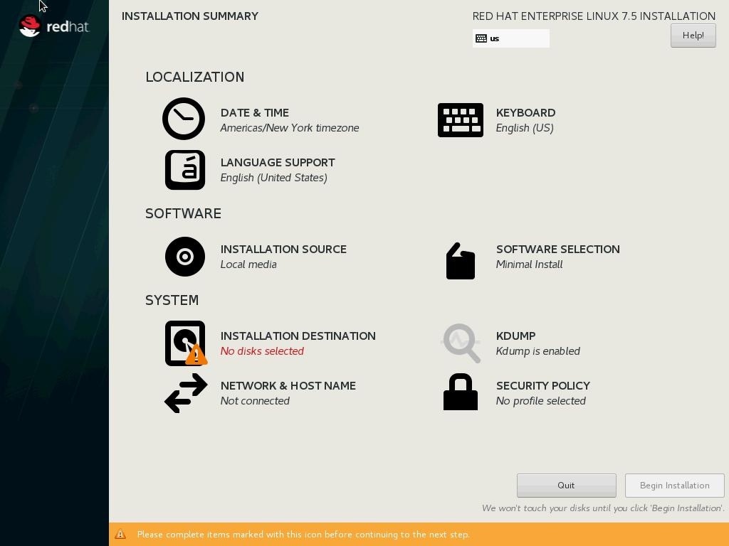
13. Click Keyboard; choose Keyboard layout and click Done.
14. Under Software Menu, click Software selection.
15. In the Base Environment choose Infrastructure Server.
16. For Add-Ons for Selected Environment choose Large Systems Performance, Network File System Client, Performance Tools, Compatibility Libraries and click Done.
Figure 111 Red Hat Enterprise Linux 7.5 Installation Software Selection
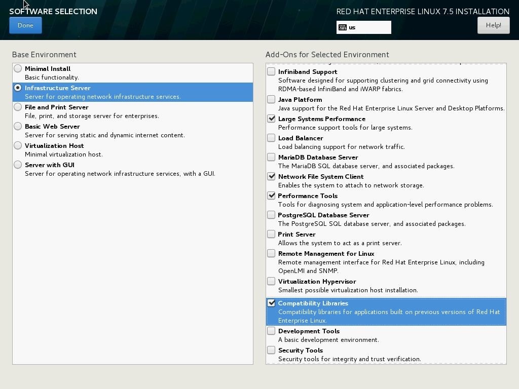
17. Under System; click Installation destination. Select Specialized & Network Disks’s “Add a disk.”
Figure 112 Red Hat Enterprise Linux 7.5 Installation Destination Disk

18. Under Multipath Devices, select the lone 100G device identifies by its WWID. Click Done.
Figure 113 Red Hat Enterprise Linux 7.5 Installation Destination Multipath Device
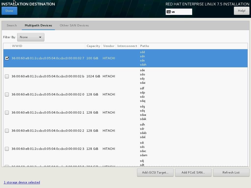
19. From the Other Storage Options choose ‘I will configure partitioning’ and click Done.
Figure 114 Red Hat Enterprise Linux 7.5 Installation Device Selection
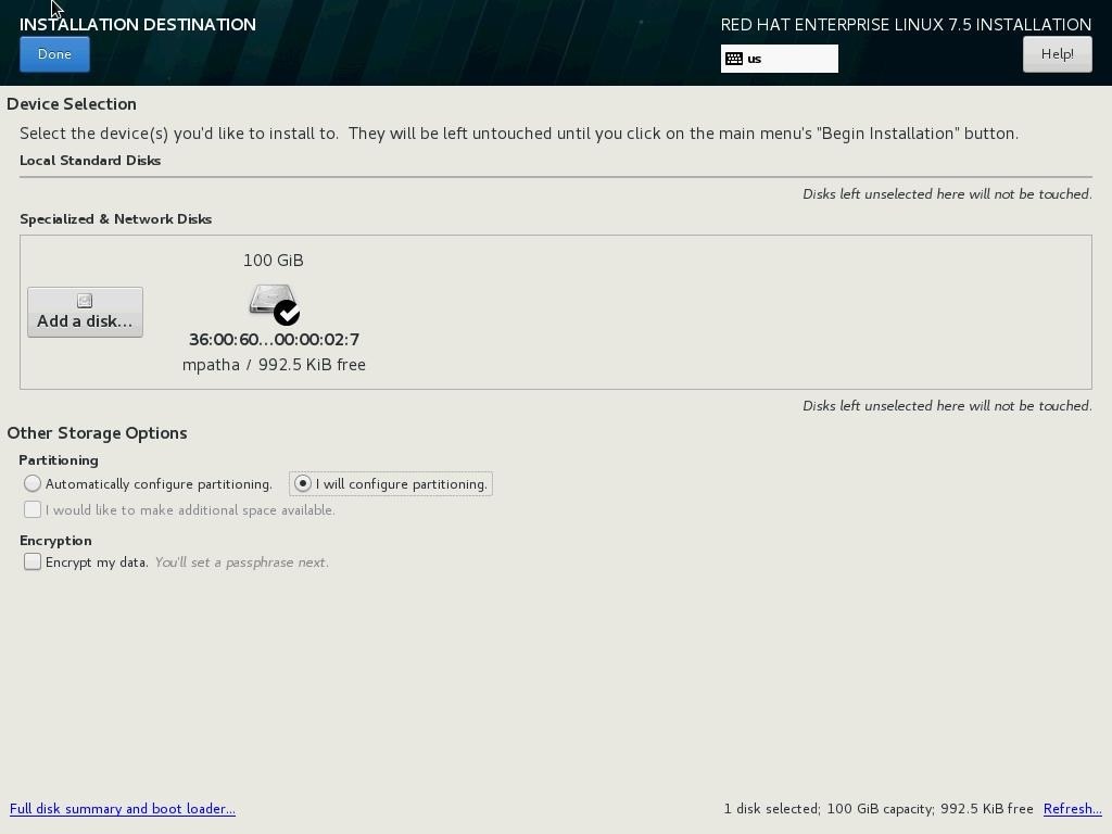
20. In the Manual Partitioning Screen, choose Standard Partition for New mount points will use the following partitioning scheme.
Figure 115 Red Hat Enterprise Linux 7.5 Installation Disk Partitioning
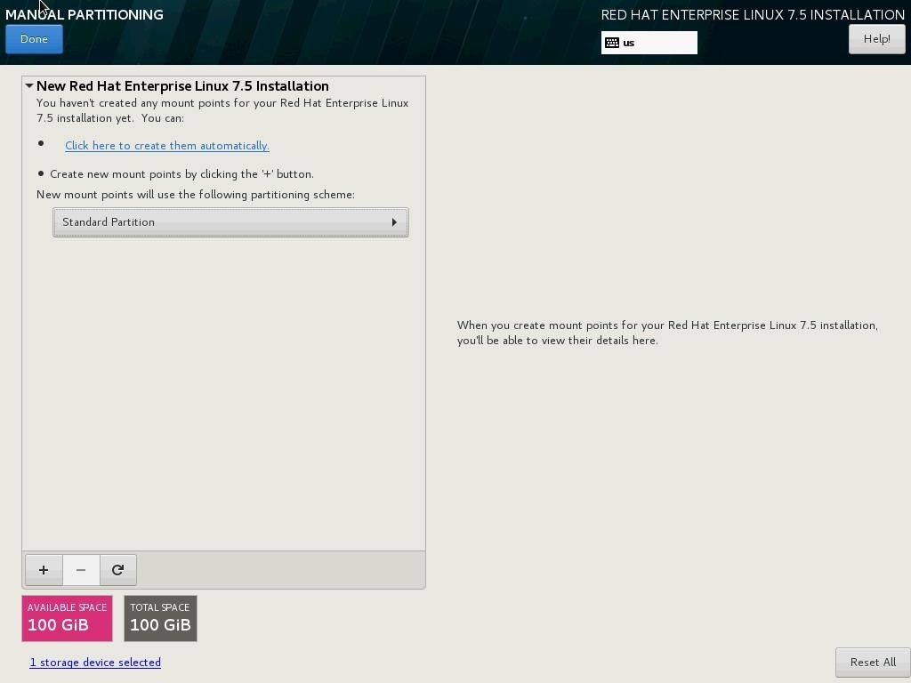
21. Click the + symbol to add a new partition.
22. Choose the mount point as ‘/boot.
23. Enter the Desired capacity as 1024 MiB and click Add Mount Point.
Figure 116 Red Hat Enterprise Linux 7.5 Installation Disk Partitioning for /boot
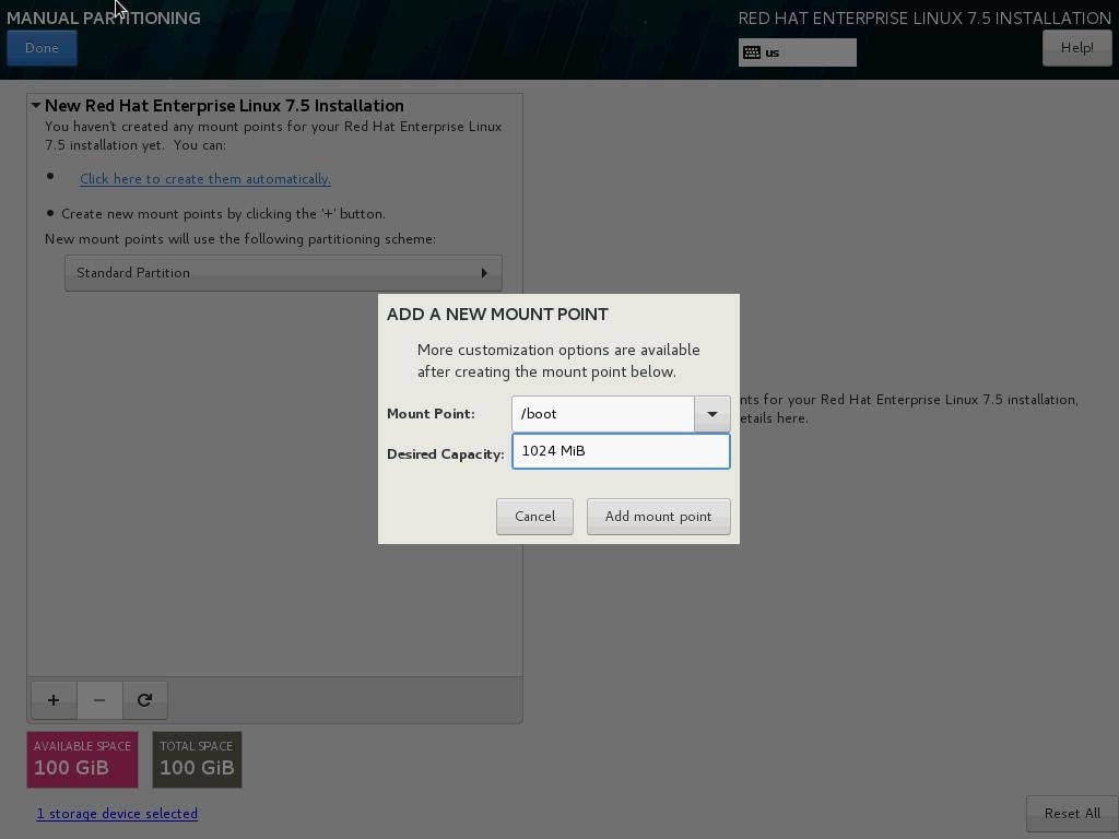
24. Choose the filesystem ext3.
25. Click the + symbol to add a new partition.
26. Choose the mount point swap.
27. Enter the Desired capacity 2048 MiB and click Add Mount Point.
28. Choose the filesystem swap.
29. Click the + symbol to add / (root) partition.
30. Choose the mount point as /.
31. Enter the Desired capacity blank and click Add Mount Point.
32. Choose the filesystem ext3.
Figure 117 Red Hat Enterprise Linux 7.5 Installation Disk Partitioning Summary
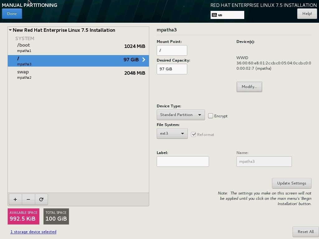
33. Click Done.
34. Review the partition layout and the size.
35. Click Accept Changes to proceed to the next steps.
36. Click KDUMP.
Figure 118 Red Hat Enterprise Linux 7.5 Installation Disable kdump
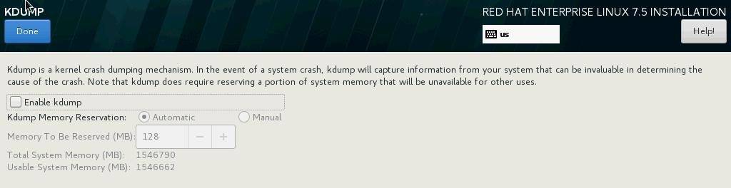
37. Deselect Enable kdump and click Done
38. Click Network & Hostname.
Figure 119 Red Hat Enterprise Linux 7.5 Installation Network and Hostname
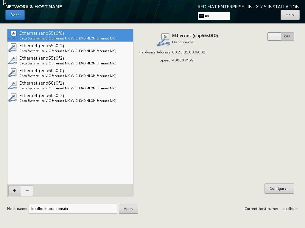
39. Enter the Host name and click Apply.
40. On the NETWORK & HOSTNAME, click Ethernet:
a. To configure the network interface on the OS, it is required to identify the mapping of the Ethernet device on the OS to vNIC interface on the Cisco UCS.
b. In Cisco UCS Manager, click the Servers tab in the navigation pane.
c. Select Service Profile > root > Sub-Organization > T01-HANA > HANA-ScaleUp-03.
d. On the main pane click on Network, list of the vNICs with MAC Address are listed.
e. Note that the MAC Address of the HANA-Mgmt vNIC is “00:25:B5:00:0A:0B”
Figure 120 Cisco UCS vNIC MAC Access
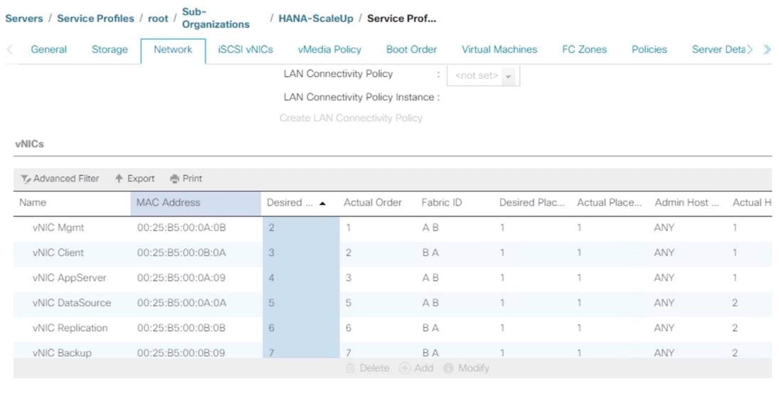
f. By comparing MAC Address on the OS and Cisco UCS, Ethernet (enp55s0f0) on OS will carry the VLAN for Management.
Figure 121 Red Hat Enterprise Linux 7.5 Installation Network and Hostname
41. Click Configure:
a. Click IPv4 Settings, and choose Manual for Method.
b. Under Addresses Click Add.
c. In the Address field enter <<Management IP address>>.
d. In the Netmask field enter <<subnet mask for Management Interface>>.
e. In the Gateway field enter <<default gateway for Management Interface>>.
f. Click Save.
Figure 122 Red Hat Enterprise Linux 7.5 Installation Network IP Address Settings
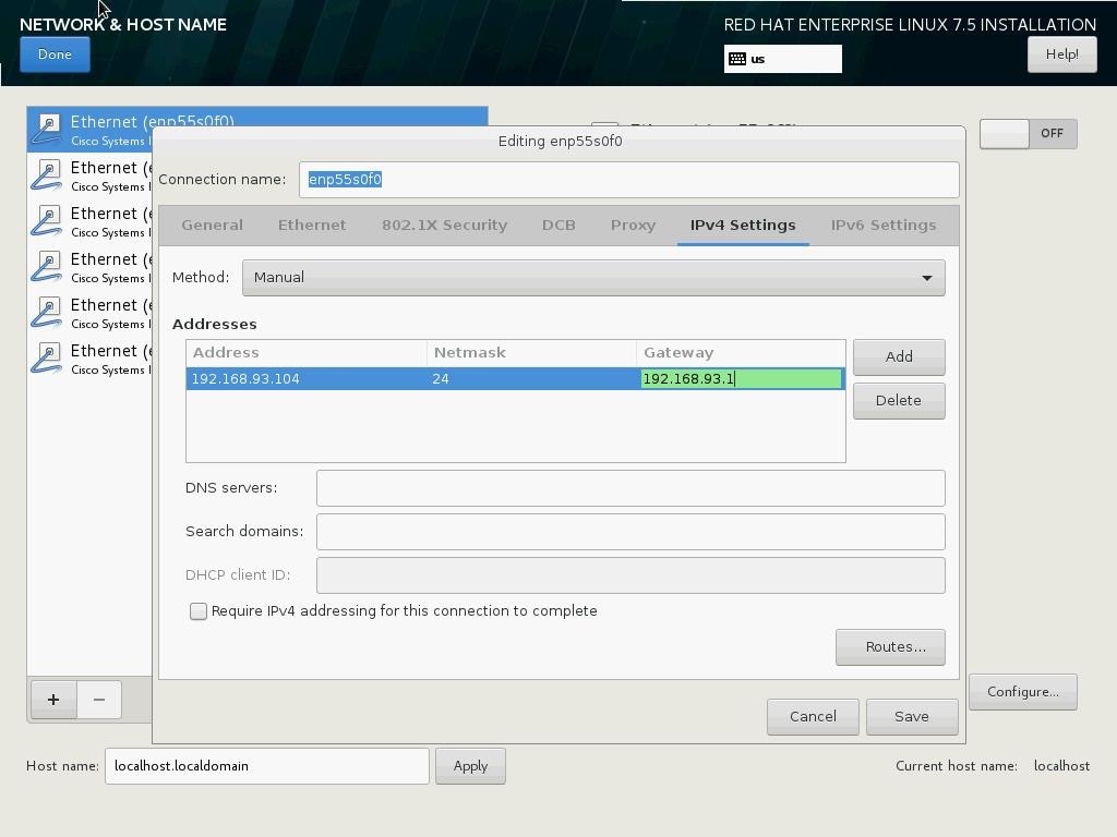
42. Enter the Host name and click Apply.
Figure 123 Red Hat Enterprise Linux 7.5 Installation Hostname Settings
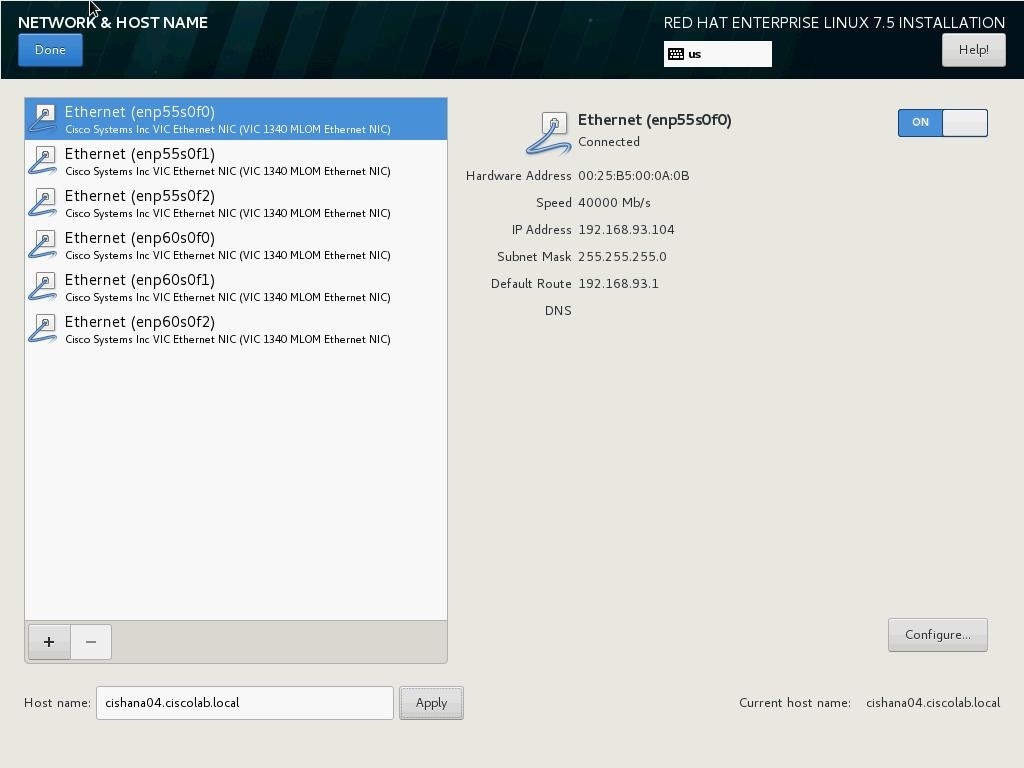
43. Click Done at the top left corner of the screen.
44. IP address for rest of the Ethernet will be set post installation, by using ssh to connect to the server on Management IP.
45. Review the installation summary and click Begin Installation.
Figure 124 Red Hat Enterprise Linux 7.5 Installation Summary
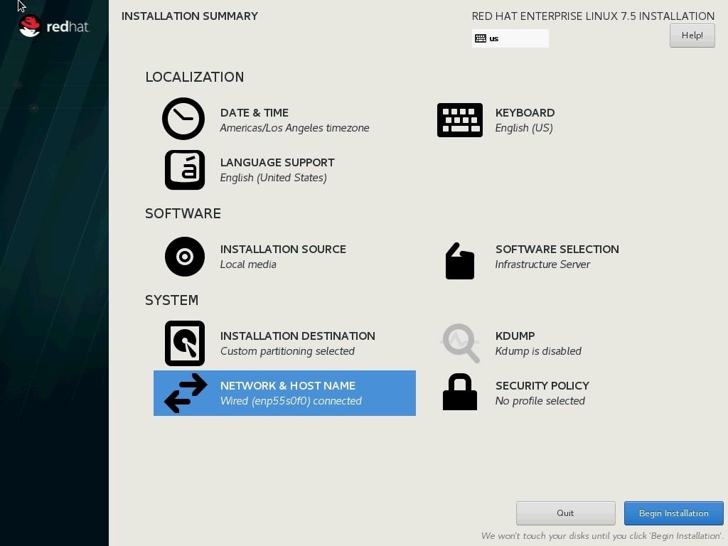
46. The next screen will show the start of the OS installation.
47. Click Root Password.
Figure 125 Red Hat Enterprise Linux 7.5 Installation Set Root Password
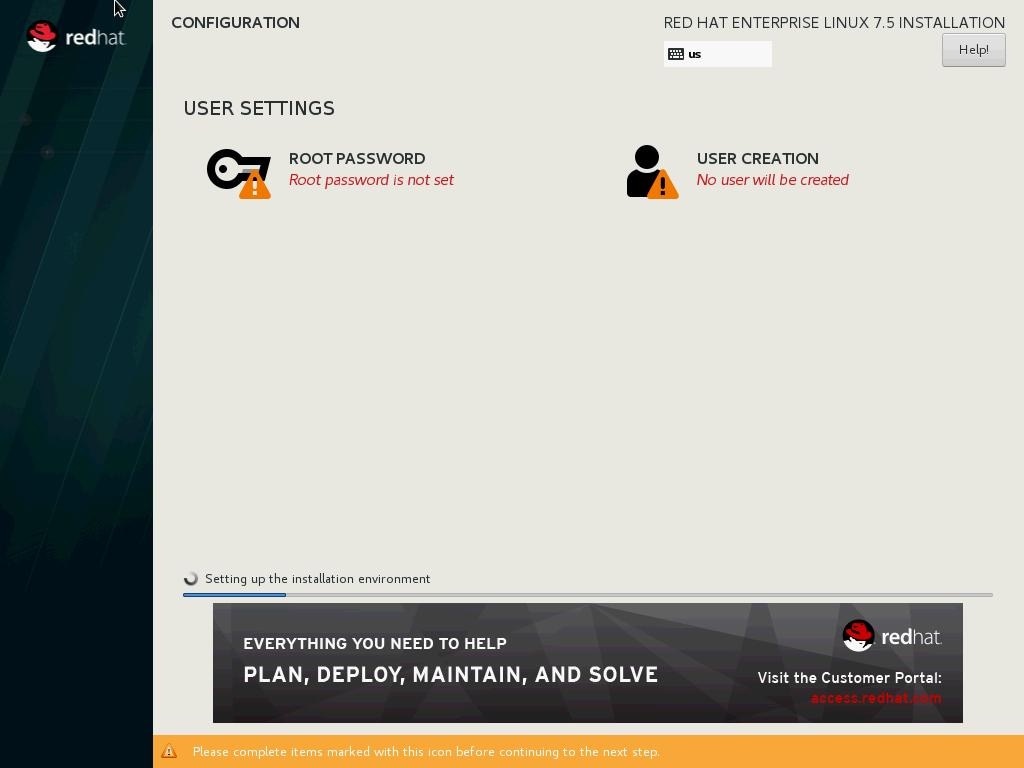
48. Enter the Root Password and Confirm.
49. Click Done.
50. The installation will start and continue.
Figure 126 Red Hat Enterprise Linux 7.5 Installation Progress
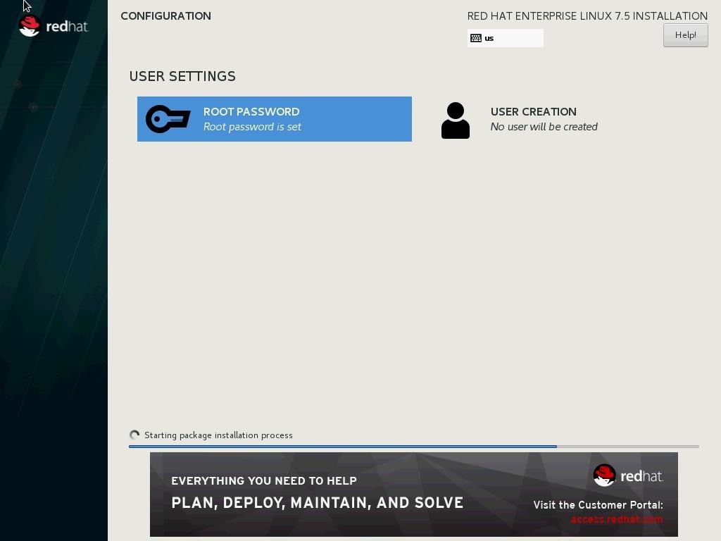
51. When the installation is complete click Reboot to finish the installation.
Network Services Configuration
To configure the server with Network services, follow these steps:
Hostnames
The operating system must be configured such a way that the short name of the server is displayed for the command ‘hostname’ and Full Qualified Host Name is displayed with the command ‘hostname –d’.
1. Use the KVM console to log in to the installed system as the user root and the password <<var_sys_root-pw>>.
2. Set the hostname using hostnamectl:
hostnamectl set-hostname <<hostname>>
IP Address
Each SAP HANA Server is configured with 6 vNIC device. Table 22 lists the IP Address information required to configure the IP address on the Operating System.
![]() The IP Address and Subnet Mask provided below are examples only, please configure the IP address for your environment.
The IP Address and Subnet Mask provided below are examples only, please configure the IP address for your environment.
Table 22 IP Addresses for SAP HANA Server
| vNIC Name |
VLAN ID |
IP Address Range |
Subnet Mask |
| HANA-AppServer |
<<var_appserver_vlan_id>> |
192.168.223.103 |
255.255.255.0 |
| HANA-Backup |
<<var_backup_vlan_id>> |
192.168.221.103 |
255.255.255.0 |
| HANA-Client |
<<var_client_vlan_id>> |
192.168.222.103 |
255.255.0.0 |
| HANA-DataSource |
<<var_datasource_vlan_id>> |
192.168.224.103 |
255.255.255.0 |
| HANA-Replication |
<<var_replication_vlan_id>> |
192.168.225.103 |
255.255.255.0 |
| Management |
<<var_mgmt_vlan_id>> |
192.168.93.103 |
255.255.0.0 |
1. To configure the network interface on the OS, it is required to identify the mapping of the ethernet device on the OS to vNIC interface on the Cisco UCS.
2. In RHEL 7, systemd and udev support a number of different naming schemes. By default, fixed names are assigned based on firmware, topology, and location information, like ‘enp72s0’. With this naming convention, though names stay fixed even if hardware is added or removed it is often harder to read unlike traditional kernel-native ethX naming “eth0”. Another way to name network interfaces, “biosdevnames”, is already available with installation.
3. Configure boot parameters "net.ifnames=0 biosdevname=0" to disable both, to get the original kernel native network names.
4. Also, IPV6 support could be disabled at this time as we use IPV4 in the solution. This can be done by appending ipv6.disable=1 to GRUB_CMDLINE_LINUX as shown below:
cat /etc/default/grub
GRUB_TIMEOUT=5
GRUB_DISTRIBUTOR="$(sed 's, release .*$,,g' /etc/system-release)"
GRUB_DEFAULT=saved
GRUB_DISABLE_SUBMENU=true
GRUB_TERMINAL_OUTPUT="console"
GRUB_CMDLINE_LINUX="rhgb quiet net.ifnames=0 biosdevname=0 ipv6.disable=1"
GRUB_DISABLE_RECOVERY="true"
5. To Run the grub2-mkconfig command to regenerate the grub.cfg file:
grub2-mkconfig -o /boot/grub2/grub.cfg
6. Finally reboot system to effect the changes.
7. To configure the network interface on the OS, it is required to identify the mapping of the ethernet device on the OS to vNIC interface on the Cisco UCS.
8. From the OS, run the following command to get list of Ethernet device with MAC Address:
[root@cishana03 ~]# ip addr
lo: <LOOPBACK,UP,LOWER_UP> mtu 65536 qdisc noqueue state UNKNOWN group default qlen 1000
link/loopback 00:00:00:00:00:00 brd 00:00:00:00:00:00
inet 127.0.0.1/8 scope host lo
valid_lft forever preferred_lft forever
2: eth0: <BROADCAST,MULTICAST,UP,LOWER_UP> mtu 9000 qdisc mq state UP group default qlen 1000
link/ether 00:25:b5:00:0b:09 brd ff:ff:ff:ff:ff:ff
3: eth1: <BROADCAST,MULTICAST,UP,LOWER_UP> mtu 9000 qdisc mq state UP group default qlen 1000
link/ether 00:25:b5:00:0a:0a brd ff:ff:ff:ff:ff:ff
4: eth2: <BROADCAST,MULTICAST,UP,LOWER_UP> mtu 9000 qdisc mq state UP group default qlen 1000
link/ether 00:25:b5:00:0b:0b brd ff:ff:ff:ff:ff:ff
5: eth3: <BROADCAST,MULTICAST,UP,LOWER_UP> mtu 9000 qdisc mq state UP group default qlen 1000
link/ether 00:25:b5:00:0b:0a brd ff:ff:ff:ff:ff:ff
6: eth4: <BROADCAST,MULTICAST,UP,LOWER_UP> mtu 9000 qdisc mq state UP group default qlen 1000
link/ether 00:25:b5:00:0a:09 brd ff:ff:ff:ff:ff:ff
7: eth5: <BROADCAST,MULTICAST,UP,LOWER_UP> mtu 9000 qdisc mq state UP group default qlen 1000
link/ether 00:25:b5:00:0a:0b brd ff:ff:ff:ff:ff:ff
9. In Cisco UCS Manager, click the Servers tab in the navigation pane.
10. Select Service Profile > root > Sub-Organization > T01-HANA > HANA-ScaleUp-03
11. On the main pane click Network; the list of the vNICs with MAC Address are listed.
Figure 127 Cisco UCS vNIC MAC Address
12. Note the MAC Address of the HANA-Client vNIC is “00:25:B5:00:0B:0A”.
13. By comparing MAC Address on the OS and Cisco UCS, eth5 on OS will carry the VLAN for HANA-Client.
14. Go to network configuration directory and create a configuration for eth3:
cd /etc/sysconfig/network-scripts/
vi ifcfg-eth3
DEVICE=eth3
TYPE=Ethernet
ONBOOT=yes
BOOTPROTO=static
IPV6INIT=no
USERCTL=no
NM_CONTROLLED=no
IPADDR=192.168.221.103
IPADDR=<<IP address for HANA-Client network example:192.168.222.103>>
NETMASK=<<subnet mask for HANA-Client network 255.255.255.0>>
15. Repeat steps 12 through 18 for each vNIC interface.
16. Add default gateway:
vi /etc/sysconfig/network
NETWORKING=yes
HOSTNAME=<<HOSTNAME>>
GATEWAY=<<IP Address of default gateway>>
DNS
Domain Name Service configuration must be done based on the local requirements.
Add DNS Servers entry:
vi /etc/resolv.conf
nameserver <<IP of DNS Server1>>
nameserver <<IP of DNS Server2>>
search <<Domain_name>>
Hosts File
HANA nodes should be able to resolve internal network IP address, below is an example of Scale Up HANA System host file with the entire network defined in the /etc/hosts file.
root@cishana03 ~]# cat /etc/hosts
127.0.0.1 localhost localhost.localdomain localhost4 localhost4.localdomain4
::1 localhost localhost.localdomain localhost6 localhost6.localdomain6
192.168.93.103 cishana03m.ciscolab.local cishana03m
192.168.222.103 cishana03c.ciscolab.local cishana03c
192.168.223.103 cishana03.ciscolab.local cishana03
192.168.224.103 cishana03d.ciscolab.local cishana03d
192.168.225.103 cishana03r.ciscolab.local cishana03r
192.168.221.103 cishana03b.ciscolab.local cishana03b
RHEL 7.5 System Update and OS Customization for SAP HANA
To update and customize SAP HANA, follow these steps:
1. In order to patch the system, the repository must be updated. Note that the installed system doesn’t include any update information. In order to patch the RedHat System, it must be registered and attached to a valid Subscription. The following line will register the installation and update the repository information.
subscription-manager register --auto-attach
Username: <<username>>
Password: <<password>>
2. If proxy server is required to access the internet, please update the proxy settings using
subscription-manager config --server.proxy_hostname=<<proxy_server_IP_address>>
subscription-manager config --server.proxy_port=<<proxy_server_port>>
3. Update only the OS kernel and firmware packages to the latest release that appeared in RHEL 7.5. Set the release version to 7.5
subscription-manager release –set=7.5
4. Add the repos required for SAP HANA.
subscription-manager repos --disable "*"
subscription-manager repos --enable rhel-7-server-rpms --enable rhel-sap-hana-for-rhel-7-server-rpms
5. Apply the latest updates for RHEL 7.5 Typically, the kernel is updated as well:
yum -y update
6. Install dependencies in accordance with the SAP HANA Server Installation and Update Guide. The numactl package if the benchmark HWCCT is to be used.
yum -y install gtk2 libicu xulrunner sudo tcsh libssh2 expect cairo graphviz iptraf krb5-workstation libpng12 krb5-libs nfs-utils lm_sensors rsyslog compat-sap-c++-* openssl098e openssl PackageKit-gtk-module libcanberra-gtk2 libtool-ltdl xorg-x11-xauth compat-libstdc++-33 numactl libuuid uuidd e2fsprogs icedtea-web xfsprogs net-tools bind-utils glibc-devel libgomp
7. Disable SELinux:
sed -i 's/^SELINUX=enforcing/SELINUX=disabled/g' /etc/sysconfig/selinux
sed -i 's/^SELINUX=permissive/SELINUX=disabled/g' /etc/sysconfig/selinux
sed -i 's/^SELINUX=enforcing/SELINUX=disabled/g' /etc/selinux/config
sed -i 's/^SELINUX=permissive/SELINUX=disabled/g' /etc/selinux/config
8. For compatibility reasons, four symbolic links are required:
ln -s /usr/lib64/libssl.so.0.9.8e /usr/lib64/libssl.so.0.9.8
ln -s /usr/lib64/libssl.so.1.0.1e /usr/lib64/libssl.so.1.0.1
ln -s /usr/lib64/libcrypto.so.0.9.8e /usr/lib64/libcrypto.so.0.9.8
ln -s /usr/lib64/libcrypto.so.1.0.1e /usr/lib64/libcrypto.so.1.0.1
9. The Linux kernel shipped with RHEL 7 includes a cpuidle driver for recent Intel CPUs: intel_idle. This driver leads to a different behavior in C-states switching. The normal operating state is C0, when the processor is put to a higher C state, which saves power. But for low latency applications, the additional time needed to stop and start the execution of the code will cause performance degradations. Modify the file /etc/default/grub and append the following parameter to the line starting with GRUB_CMDLINE_LINUX:
transparent_hugepage=never intel_idle.max_cstate=1 processor.max_cstate=1
10. To implement these changes, rebuild the GRUB2 configuration:
grub2-mkconfig -o /boot/grub2/grub.cfg
11. Turn off auto-numa balancing: SAP HANA is a NUMA (non-uniform memory access) aware database. Thus it does not rely on the Linux kernel's features to optimize NUMA usage automatically. Depending on the workload, it can be beneficial to turn off automatically NUMA balancing. For this purpose, add "kernel.numa_balancing = 0" to /etc/sysctl.d/sap_hana.conf (please create this file if it does not already exist) and reconfigure the kernel by running:
echo "kernel.numa_balancing = 0" >> /etc/sysctl.d/sap_hana.conf
sysctl -p /etc/sysctl.d/sap_hana.conf
12. The "numad" daemon must be disable:
systemctl stop numad
systemctl disable numad
13. Configure tuned to use profile "sap-hana." The tuned profile "sap-hana", which is provided by Red Hat as part of RHEL 7 for SAP Solutions, contains many of the configures some additional settings. Therefore the "sap-hana" tuned profile must be activated on all systems running SAP HANA:
yum install tuned-profiles-sap-hana
systemctl start tuned
systemctl enable tuned
tuned-adm profile sap-hana
14. Disable ABRT, Crash Dump:
systemctl disable abrtd
systemctl disable abrt-ccpp
systemctl stop abrtd
systemctl stop abrt-ccpp
15. Disable core file creation. To disable core dumps for all users, open /etc/security/limits.conf, and add the line:
* soft core 0
* hard core 0
16. Enable group "sapsys" to create an unlimited number of processes:
echo "@sapsys soft nproc unlimited" > /etc/security/limits.d/99-sapsys.conf
17. Disable Firewall:
systemctl stop firewalld
systemctl disable firewalld
18. Reboot the OS by issuing reboot command.
19. Optional: old kernels can be removed after OS update:
package-cleanup --oldkernels --count=1 -y
![]() The Operating System Installation and configurations documented in this CVD are from SAP Notes at the time of publication, for latest setting please follow the SAP Notes in the References section
The Operating System Installation and configurations documented in this CVD are from SAP Notes at the time of publication, for latest setting please follow the SAP Notes in the References section
Install Cisco eNIC and fNIC Driver
To download the Cisco UCS Drivers ISO bundle, which contains most of the Cisco UCS Virtual Interface Card drivers, follow these steps:
1. In a web browser, navigate to https://software.cisco.com/download/home/283853163/type/283853158/release/redhat
![]() You must be signed in to download Cisco Unified Computing System (UCS) drivers.
You must be signed in to download Cisco Unified Computing System (UCS) drivers.
2. After the download is complete browse to
a. cisco-ucs-drivers-1.1901.1.0-redhat.iso\7.5\network\cisco\vic\3.1.137.5 and copy kmod-enic-3.1.137.5-700.16.rhel7u5.x86_64.rpm to HANA server
b. cisco-ucs-drivers-1.1901.1.0-redhat.iso\7.5\storage\cisco\vic\1.6.0.47 and copy kmod-fnic-1.6.0.47-rhel7u5.el7.x86_64.rpm to HANA server
3. ssh to the Server as root.
4. Update the enic driver with below command
rpm -Uvh kmod-enic-3.1.137.5-700.16.rhel7u5.x86_64.rpm
5. Update the fnic driver with below command
rpm -Uvh kmod-fnic-1.6.0.47-rhel7u5.el7.x86_64.rpm
Network Time
The configuration of NTP is important and must be performed on all systems. To configure network time, follow these steps:
1. Install NTP-server with utilities.
yum -y install ntp ntpdate
2. Configure NTP by adding at least one NTP server to the NTP config file /etc/ntp.conf.
vi /etc/ntp.conf
server <<var_oob_ntp>>
3. Stop the NTP services and update the NTP Servers.
systemctl stop ntpd
ntpdate ntp.example.com
4. Start NTP service and configure it to be started automatically.
systemctl enable ntpd.service
systemctl start ntpd.service
systemctl restart systemd-timedated.service
Multipath Configuration
This reference architecture uses Device-mapper Multipath, a native component of the Linux operating system. Using Device-mapper Multipath allows the configuration of multiple I/O paths between the server blades and storages.
Each node has two I/O paths connected with the storage. Multipathing aggregates all physical I/O paths into a single logical path. The LUNs are always available unless both paths fail.
Device-mapper Multipath is used for the following I/O paths:
· SAP HANA server boot volume
· SAP HANA data volume
· SAP HANA log volume
· SAP HANA shared volume
1. ssh to the Server as root.
2. Create the following entry in /etc/multipath.conf:
vi /etc/multipath.conf
defaults {
find_multipaths yes
user_friendly_names yes
}
blacklist {
devnode "^(ram|raw|loop|fd|md|dm-|sr|scd|st)[0-9]*"
devnode "^hd[a-z]"
devnode "^dcssblk[0-9]*"
}
devices {
device {
vendor "HITACHI"
product ".*"
user_friendly_names no
path_checker directio
path_grouping_policy multibus
path_selector "queue-length 0"
uid_attribute ID_SERIAL
failback immediate
rr_weight uniform
rr_min_io_rq 1
features 0
no_path_retry 5
}
}
3. Restart the multipath daemon and enable to start at the boot:
systemctl stop multipathd
systemctl start multipathd
systemctl enable multipathd
4. Check the status of multipath devices using multipath –ll:
multipath -ll
360060e8012ccbc005040ccbc00000027 dm-8 HITACHI ,OPEN-V
size=100G features='1 queue_if_no_path' hwhandler='0' wp=rw
`-+- policy='queue-length 0' prio=1 status=active
|- 3:0:0:0 sda 8:0 active ready running
|- 3:0:1:0 sdk 8:160 active ready running
|- 6:0:0:0 sdu 65:64 active ready running
`- 6:0:1:0 sdae 65:224 active ready running
360060e8012ccbc005040ccbc0000003b dm-0 HITACHI ,OPEN-V
size=384G features='1 queue_if_no_path' hwhandler='0' wp=rw
`-+- policy='queue-length 0' prio=1 status=active
|- 3:0:0:9 sdj 8:144 active ready running
|- 3:0:1:9 sdt 65:48 active ready running
|- 6:0:0:9 sdad 65:208 active ready running
`- 6:0:1:9 sdan 66:112 active ready running
360060e8012ccbc005040ccbc0000003a dm-5 HITACHI ,OPEN-V
size=384G features='1 queue_if_no_path' hwhandler='0' wp=rw
`-+- policy='queue-length 0' prio=1 status=active
|- 3:0:0:8 sdi 8:128 active ready running
|- 3:0:1:8 sds 65:32 active ready running
|- 6:0:0:8 sdac 65:192 active ready running
`- 6:0:1:8 sdam 66:96 active ready running
360060e8012ccbc005040ccbc00000039 dm-1 HITACHI ,OPEN-V
size=384G features='1 queue_if_no_path' hwhandler='0' wp=rw
`-+- policy='queue-length 0' prio=1 status=active
|- 3:0:0:7 sdh 8:112 active ready running
|- 3:0:1:7 sdr 65:16 active ready running
|- 6:0:0:7 sdab 65:176 active ready running
`- 6:0:1:7 sdal 66:80 active ready running
360060e8012ccbc005040ccbc00000038 dm-4 HITACHI ,OPEN-V
size=384G features='1 queue_if_no_path' hwhandler='0' wp=rw
`-+- policy='queue-length 0' prio=1 status=active
|- 3:0:0:6 sdg 8:96 active ready running
|- 3:0:1:6 sdq 65:0 active ready running
|- 6:0:0:6 sdaa 65:160 active ready running
`- 6:0:1:6 sdak 66:64 active ready running
360060e8012ccbc005040ccbc00000023 dm-6 HITACHI ,OPEN-V
size=128G features='1 queue_if_no_path' hwhandler='0' wp=rw
`-+- policy='queue-length 0' prio=1 status=active
|- 3:0:0:5 sdf 8:80 active ready running
|- 3:0:1:5 sdp 8:240 active ready running
|- 6:0:0:5 sdz 65:144 active ready running
`- 6:0:1:5 sdaj 66:48 active ready running
360060e8012ccbc005040ccbc00000022 dm-2 HITACHI ,OPEN-V
size=128G features='1 queue_if_no_path' hwhandler='0' wp=rw
`-+- policy='queue-length 0' prio=1 status=active
|- 3:0:0:4 sde 8:64 active ready running
|- 3:0:1:4 sdo 8:224 active ready running
|- 6:0:0:4 sdy 65:128 active ready running
`- 6:0:1:4 sdai 66:32 active ready running
360060e8012ccbc005040ccbc00000021 dm-7 HITACHI ,OPEN-V
size=128G features='1 queue_if_no_path' hwhandler='0' wp=rw
`-+- policy='queue-length 0' prio=1 status=active
|- 3:0:0:3 sdd 8:48 active ready running
|- 3:0:1:3 sdn 8:208 active ready running
|- 6:0:0:3 sdx 65:112 active ready running
`- 6:0:1:3 sdah 66:16 active ready running
360060e8012ccbc005040ccbc00000020 dm-3 HITACHI ,OPEN-V
size=128G features='1 queue_if_no_path' hwhandler='0' wp=rw
`-+- policy='queue-length 0' prio=1 status=active
|- 3:0:0:2 sdc 8:32 active ready running
|- 3:0:1:2 sdm 8:192 active ready running
|- 6:0:0:2 sdw 65:96 active ready running
`- 6:0:1:2 sdag 66:0 active ready running
360060e8012ccbc005040ccbc0000002b dm-9 HITACHI ,OPEN-V
size=1.0T features='1 queue_if_no_path' hwhandler='0' wp=rw
`-+- policy='queue-length 0' prio=1 status=active
|- 3:0:0:1 sdb 8:16 active ready running
|- 3:0:1:1 sdl 8:176 active ready running
|- 6:0:0:1 sdv 65:80 active ready running
`- 6:0:1:1 sdaf 65:240 active ready running
Configure HANA Persistent Storage Volume Configuration
For both operating systems, SUSE Linux Enterprise Server for SAP Applications and Red Hat Enterprise Linux, Hitachi uses an LVM-based storage layout. Once installing the operating system and correctly configuring multipathing, you can see the assigned LUNs in the directories:
/dev/mapper
/dev/disk/by-id
For example:
/dev/mapper/360060e801227fc00504027fc00000101
/dev/disk/by-id/scsi-360060e801227fc00504027fc00000101
The last 6 digits of this number indicates the LDEV ID you have used during the LUN assignment. In the example above, 000101 maps to LDEV ID: 00:01:01.
For all the LUNs besides of the one hosting the operating system, you need to initialize the LUNs for use by LVM, running the pvcreate command, which is part of the lvm2 rpm package, for example:
pvcreate -ff -y /dev/mapper/360060e801227fc00504027fc00000101
After you have prepared all the LUNs, you need to configure the volume groups using the vgcreate command. The names for the volume group differs between scale-up and scale-out installations.
· The volume groups for scale-up use vgdata, vglog, vgshared.
The command to create the volume group takes no specific options. The following example creates the volume group for SAP HANA log in a scale-up scenario using 4 physical disks / LUNs:
vgcreate vglog /dev/mapper/360060e801227fc00504027fc0000010[2,3,4,5]
For creating other volume groups, use the same syntax, exchanging the volume group name as well as the physical disks or LUNs.
Once creating the volume groups, you need to create a logical volume on top. The general syntax is the following:
lvcreate --yes --extents=100%VG --stripes <# luns> --stripesize 1024 --name <lv name> <volume group>
Use Table 23 to complete the creation of logical volumes.
Table 23 Details for Creating Logical Volumes
|
|
Number of LUNs |
lv Name |
vg Name |
| DATA |
4 - following this reference architecture, or the number of assigned LUNs |
lvdata |
Scale-up: vgdata |
| LOG |
4 - following this reference architecture, or the number of assigned LUNs |
lvlog |
Scale-up: vglog |
| SHARED |
1 - following this reference architecture, or the number of assigned LUNs |
lvshared |
Scale-up: vgshared |
![]() If you only use 1 LUN to create the logical volumes for data, log, or shared, the options ‑‑stripes and ‑‑stripesize are not needed.
If you only use 1 LUN to create the logical volumes for data, log, or shared, the options ‑‑stripes and ‑‑stripesize are not needed.
Create the file system on top of the logical volume. Hitachi storage arrays use the XFS file system. In Table 24 , find the options to create and mount the file system.
Table 24 File System Create and Mount Options
|
|
System Type |
Create Options |
Mount Options |
Mount Point |
| DATA |
Scale-up |
-F |
inode64, nobarrier |
/hana/data |
| LOG |
Scale-up |
-F |
inode64, nobarrier |
/hana/log |
| SHARED |
Scale-up |
-F |
inode64, nobarrier |
/hana/shared |
To create a file system, use the following command:
mkfs.xfs <create options> /dev/mapper/<vg name>-<lv name>
For example:
mkfs.xfs -F /dev/mapper/vglog-lvlog
SAP HANA Persistent Storage Volume Configuration for Scale-Up Deployments
For scale-up systems, you need to persist the file systems, including the mount options, in one of the operating system's startup file, /etc/fstab/, to mount the file systems automatically during boot operations.
Add the following entry for each filesystem to /etc/fstab:
/dev/mapper/<vg name>-<lv name> <mount point> xfs <mount options> 0 0
Refer to Table 22 and Table 22 for volume group and logical volume names as well as the mount options.
Configuration Example on SUSE Linux Enterprise Server for SAP Applications
List of assigned LUNs:
cishana02:/dev/mapper # cd /dev/mapper/
cishana02:/dev/mapper # ll
total 0
lrwxrwxrwx 1 root root 8 Mar 26 19:19 360060e8012ccbc005040ccbc00000018 -> ../dm-10
lrwxrwxrwx 1 root root 7 Mar 26 19:19 360060e8012ccbc005040ccbc00000019 -> ../dm-5
lrwxrwxrwx 1 root root 7 Mar 26 19:19 360060e8012ccbc005040ccbc0000001a -> ../dm-0
lrwxrwxrwx 1 root root 7 Mar 26 19:19 360060e8012ccbc005040ccbc0000001b -> ../dm-1
lrwxrwxrwx 1 root root 7 Mar 26 19:19 360060e8012ccbc005040ccbc00000025 -> ../dm-7
lrwxrwxrwx 1 root root 7 Mar 26 19:19 360060e8012ccbc005040ccbc00000025_part1 -> ../dm-9
lrwxrwxrwx 1 root root 7 Mar 26 19:19 360060e8012ccbc005040ccbc00000025-part1 -> ../dm-9
lrwxrwxrwx 1 root root 7 Mar 26 19:19 360060e8012ccbc005040ccbc00000029 -> ../dm-8
lrwxrwxrwx 1 root root 7 Mar 26 19:19 360060e8012ccbc005040ccbc00000030 -> ../dm-3
lrwxrwxrwx 1 root root 7 Mar 26 19:19 360060e8012ccbc005040ccbc00000031 -> ../dm-6
lrwxrwxrwx 1 root root 7 Mar 26 19:19 360060e8012ccbc005040ccbc00000032 -> ../dm-4
lrwxrwxrwx 1 root root 7 Mar 26 19:19 360060e8012ccbc005040ccbc00000033 -> ../dm-2
crw------- 1 root root 10, 236 Mar 26 19:19 control
Initialize the LUNs using pvcreate:
cishana02:/dev/mapper # pvcreate -ff -y 360060e8012ccbc005040ccbc00000018
Physical volume "360060e8012ccbc005040ccbc00000018" successfully created.
cishana02:/dev/mapper # pvcreate -ff -y 360060e8012ccbc005040ccbc00000019
Physical volume "360060e8012ccbc005040ccbc00000019" successfully created.
cishana02:/dev/mapper # pvcreate -ff -y 360060e8012ccbc005040ccbc0000001a
Physical volume "360060e8012ccbc005040ccbc0000001a" successfully created.
cishana02:/dev/mapper # pvcreate -ff -y 360060e8012ccbc005040ccbc0000001b
Physical volume "360060e8012ccbc005040ccbc0000001b" successfully created.
cishana02:/dev/mapper # pvcreate -ff -y 360060e8012ccbc005040ccbc00000029
Physical volume "360060e8012ccbc005040ccbc00000029" successfully created.
cishana02:/dev/mapper # pvcreate -ff -y 360060e8012ccbc005040ccbc00000030
Physical volume "360060e8012ccbc005040ccbc00000030" successfully created.
cishana02:/dev/mapper # pvcreate -ff -y 360060e8012ccbc005040ccbc00000031
Physical volume "360060e8012ccbc005040ccbc00000031" successfully created.
cishana02:/dev/mapper # pvcreate -ff -y 360060e8012ccbc005040ccbc00000032
Physical volume "360060e8012ccbc005040ccbc00000032" successfully created.
cishana02:/dev/mapper # pvcreate -ff -y 360060e8012ccbc005040ccbc00000033
Physical volume "360060e8012ccbc005040ccbc00000033" successfully created.
Create volume group for data:
cishana02:/dev/mapper # vgcreate vgdata /dev/mapper/360060e8012ccbc005040ccbc0000003[0,1,2,3]
Volume group "vgdata" successfully created
Create volume group for log:
cishana02:/dev/mapper # vgcreate vglog /dev/mapper/360060e8012ccbc005040ccbc0000001[8,9,a,b]
Volume group "vglog" successfully created
Create volume group for shared:
cishana02:/dev/mapper # vgcreate vgshared /dev/mapper/360060e8012ccbc005040ccbc00000029
Volume group "vgshared" successfully created
Create logical volume for data:
cishana02:/dev/mapper # lvcreate --yes --extents=100%VG --stripes 4 --stripesize 1024 --name lvdata vgdata
Logical volume "lvdata" created.
Create logical volume for log:
cishana02:/dev/mapper # lvcreate --yes --extents=100%VG --stripes 4 --stripesize 1024 --name lvlog vglog
Logical volume "lvlog" created.
Create logical volume for shared:
cishana02:/dev/mapper # lvcreate --yes --extents=100%VG --name lvshared vgshared
Logical volume "lvshared" created.
Create filesystem for data:
cishana02:/dev/mapper # mkfs.xfs -f /dev/mapper/vgdata-lvdata
meta-data=/dev/mapper/vgdata-lvdata isize=512 agcount=33, agsize=12582656 blks
= sectsz=512 attr=2, projid32bit=1
= crc=1 finobt=0, sparse=0, rmapbt=0, reflink=0
data = bsize=4096 blocks=402649088, imaxpct=5
= sunit=256 swidth=1024 blks
naming =version 2 bsize=4096 ascii-ci=0 ftype=1
log =internal log bsize=4096 blocks=196608, version=2
= sectsz=512 sunit=0 blks, lazy-count=1
realtime =none extsz=4096 blocks=0, rtextents=0
Create filesystem for log:
cishana02:/dev/mapper # mkfs.xfs -f /dev/mapper/vglog-lvlog
meta-data=/dev/mapper/vglog-lvlog isize=512 agcount=16, agsize=8388352 blks
= sectsz=512 attr=2, projid32bit=1
= crc=1 finobt=0, sparse=0, rmapbt=0, reflink=0
data = bsize=4096 blocks=134213632, imaxpct=25
= sunit=256 swidth=1024 blks
naming =version 2 bsize=4096 ascii-ci=0 ftype=1
log =internal log bsize=4096 blocks=65536, version=2
= sectsz=512 sunit=0 blks, lazy-count=1
realtime =none extsz=4096 blocks=0, rtextents=0
Create filesystem for shared:
cishana02:/dev/mapper # mkfs.xfs -f /dev/mapper/vgshared-lvshared
meta-data=/dev/mapper/vgshared-lvshared isize=512 agcount=4, agsize=67108608 blks
= sectsz=512 attr=2, projid32bit=1
= crc=1 finobt=0, sparse=0, rmapbt=0, reflink=0
data = bsize=4096 blocks=268434432, imaxpct=25
= sunit=0 swidth=0 blks
naming =version 2 bsize=4096 ascii-ci=0 ftype=1
log =internal log bsize=4096 blocks=131071, version=2
= sectsz=512 sunit=0 blks, lazy-count=1
realtime =none extsz=4096 blocks=0, rtextents=0
Create mount directories for the data, log, and HANA shared file systems:
mkdir -p /hana/data
mkdir -p /hana/log
mkdir -p /hana/shared
Add the following entry to /etc/fstab:
#HANA Volume
/dev/mapper/vgshared-lvshared /hana/shared xfs inode64,nobarrier 0 0
/dev/mapper/vgdata-lvdata /hana/data xfs inode64,nobarrier 0 0
/dev/mapper/vglog-lvlog /hana/log xfs inode64,nobarrier 0 0
Use the following command to mount the file systems from /etc/fstab:
mount -a
Use the df –h command to check the status of all mounted volumes:
cishana02:/ # df -h
Filesystem Size Used Avail Use% Mounted on
devtmpfs 756G 0 756G 0% /dev
tmpfs 1.2T 0 1.2T 0% /dev/shm
tmpfs 756G 13M 756G 1% /run
tmpfs 756G 0 756G 0% /sys/fs/cgroup
/dev/mapper/360060e8012ccbc005040ccbc00000025-part1 98G 5.3G 92G 6% /
tmpfs 152G 0 152G 0% /run/user/0
/dev/mapper/vgshared-lvshared 1.0T 33M 1.0T 1% /hana/shared
/dev/mapper/vgdata-lvdata 1.5T 34M 1.5T 1% /hana/data
/dev/mapper/vglog-lvlog 512G 33M 512G 1% /hana/log
Change the directory permissions before installing SAP HANA. Use the chmod command on each volume after the file systems are mounted:
chmod -R 777 /hana/data/
chmod -R 777 /hana/log
chmod -R 777 /hana/shared/
Configuration Example on Red Hat Enterprise Linux
List of assigned LUNs:
[root@cishana04 mapper]# cd /dev/mapper/
[root@cishana04 mapper]# ll
total 0
lrwxrwxrwx 1 root root 7 Mar 26 19:16 360060e8012ccbc005040ccbc00000020 -> ../dm-3
lrwxrwxrwx 1 root root 7 Mar 26 19:16 360060e8012ccbc005040ccbc00000021 -> ../dm-7
lrwxrwxrwx 1 root root 7 Mar 26 19:16 360060e8012ccbc005040ccbc00000022 -> ../dm-2
lrwxrwxrwx 1 root root 7 Mar 26 19:16 360060e8012ccbc005040ccbc00000023 -> ../dm-6
lrwxrwxrwx 1 root root 7 Mar 26 19:16 360060e8012ccbc005040ccbc00000027 -> ../dm-8
lrwxrwxrwx 1 root root 8 Mar 26 19:16 360060e8012ccbc005040ccbc00000027p1 -> ../dm-10
lrwxrwxrwx 1 root root 8 Mar 26 19:16 360060e8012ccbc005040ccbc00000027p2 -> ../dm-11
lrwxrwxrwx 1 root root 8 Mar 26 19:16 360060e8012ccbc005040ccbc00000027p3 -> ../dm-12
lrwxrwxrwx 1 root root 7 Mar 26 19:16 360060e8012ccbc005040ccbc0000002b -> ../dm-9
lrwxrwxrwx 1 root root 7 Mar 26 19:16 360060e8012ccbc005040ccbc00000038 -> ../dm-4
lrwxrwxrwx 1 root root 7 Mar 26 19:16 360060e8012ccbc005040ccbc00000039 -> ../dm-1
lrwxrwxrwx 1 root root 7 Mar 26 19:16 360060e8012ccbc005040ccbc0000003a -> ../dm-5
lrwxrwxrwx 1 root root 7 Mar 26 19:16 360060e8012ccbc005040ccbc0000003b -> ../dm-0
crw------- 1 root root 10, 236 Mar 22 19:23 control
Initialize the LUNs using pvcreate:
[root@cishana04 mapper]# pvcreate -ff -y 360060e8012ccbc005040ccbc00000020
Physical volume "360060e8012ccbc005040ccbc00000020" successfully created.
[root@cishana04 mapper]# pvcreate -ff -y 360060e8012ccbc005040ccbc00000021
Physical volume "360060e8012ccbc005040ccbc00000021" successfully created.
[root@cishana04 mapper]# pvcreate -ff -y 360060e8012ccbc005040ccbc00000022
Physical volume "360060e8012ccbc005040ccbc00000022" successfully created.
[root@cishana04 mapper]# pvcreate -ff -y 360060e8012ccbc005040ccbc00000023
Physical volume "360060e8012ccbc005040ccbc00000023" successfully created.
[root@cishana04 mapper]# pvcreate -ff -y 360060e8012ccbc005040ccbc0000002b
Physical volume "360060e8012ccbc005040ccbc0000002b" successfully created.
[root@cishana04 mapper]# pvcreate -ff -y 360060e8012ccbc005040ccbc00000038
Physical volume "360060e8012ccbc005040ccbc00000038" successfully created.
[root@cishana04 mapper]# pvcreate -ff -y 360060e8012ccbc005040ccbc00000039
Physical volume "360060e8012ccbc005040ccbc00000039" successfully created.
[root@cishana04 mapper]# pvcreate -ff -y 360060e8012ccbc005040ccbc0000003a
Physical volume "360060e8012ccbc005040ccbc0000003a" successfully created.
[root@cishana04 mapper]# pvcreate -ff -y 360060e8012ccbc005040ccbc0000003b
Physical volume "360060e8012ccbc005040ccbc0000003b" successfully created.
Create volume group for data:
[root@cishana04 mapper]# vgcreate vgdata /dev/mapper/360060e8012ccbc005040ccbc0000003[8,9,a,b]
Volume group "vgdata" successfully created
Create volume group for log:
[root@cishana04 mapper]# vgcreate vglog /dev/mapper/360060e8012ccbc005040ccbc0000002[0,1,2,3]
Volume group "vglog" successfully created
Create volume group for shared:
[root@cishana04 mapper]# vgcreate vgshared /dev/mapper/360060e8012ccbc005040ccbc0000002b
Volume group "vgshared" successfully created
Create logical volume for data:
[root@cishana04 mapper]# lvcreate --yes --extents=100%VG --stripes 4 --stripesize 1024 --name lvdata vgdata
Logical volume "lvdata" created.
Create logical volume for log:
[root@cishana04 mapper]# lvcreate --yes --extents=100%VG --stripes 4 --stripesize 1024 --name lvlog vglog
Logical volume "lvlog" created.
Create logical volume for shared:
[root@cishana04 mapper]# lvcreate --yes --extents=100%VG --name lvshared vgshared
Logical volume "lvshared" created.
Create filesystem for data:
[root@cishana04 mapper]# mkfs.xfs -f /dev/mapper/vgdata-lvdata
meta-data=/dev/mapper/vgdata-lvdata isize=512 agcount=33, agsize=12582656 blks
= sectsz=512 attr=2, projid32bit=1
= crc=1 finobt=0, sparse=0
data = bsize=4096 blocks=402649088, imaxpct=5
= sunit=256 swidth=1024 blks
naming =version 2 bsize=4096 ascii-ci=0 ftype=1
log =internal log bsize=4096 blocks=196608, version=2
= sectsz=512 sunit=8 blks, lazy-count=1
realtime =none extsz=4096 blocks=0, rtextents=0
Create filesystem for log:
[root@cishana04 mapper]# mkfs.xfs -f /dev/mapper/vglog-lvlog
meta-data=/dev/mapper/vglog-lvlog isize=512 agcount=16, agsize=8388352 blks
= sectsz=512 attr=2, projid32bit=1
= crc=1 finobt=0, sparse=0
data = bsize=4096 blocks=134213632, imaxpct=25
= sunit=256 swidth=1024 blks
naming =version 2 bsize=4096 ascii-ci=0 ftype=1
log =internal log bsize=4096 blocks=65536, version=2
= sectsz=512 sunit=8 blks, lazy-count=1
realtime =none extsz=4096 blocks=0, rtextents=0
Create filesystem for shared:
[root@cishana04 mapper]# mkfs.xfs -f /dev/mapper/vgshared-lvshared
meta-data=/dev/mapper/vgshared-lvshared isize=512 agcount=4, agsize=67108608 blks
= sectsz=512 attr=2, projid32bit=1
= crc=1 finobt=0, sparse=0
data = bsize=4096 blocks=268434432, imaxpct=25
= sunit=0 swidth=0 blks
naming =version 2 bsize=4096 ascii-ci=0 ftype=1
log =internal log bsize=4096 blocks=131071, version=2
= sectsz=512 sunit=0 blks, lazy-count=1
realtime =none extsz=4096 blocks=0, rtextents=0
Create mount directories for the data, log, and HANA shared file systems:
mkdir -p /hana/data
mkdir -p /hana/log
mkdir -p /hana/shared
Add the following entry to /etc/fstab:
#HANA Volume
/dev/mapper/vgshared-lvshared /hana/shared xfs inode64,nobarrier 0 0
/dev/mapper/vgdata-lvdata /hana/data xfs inode64,nobarrier 0 0
/dev/mapper/vglog-lvlog /hana/log xfs inode64,nobarrier 0 0
Use the following command to mount the file systems from /etc/fstab:
mount -a
Use the df –h command to check the status of all mounted volumes:
[root@cishana04 mapper]# df -h
Filesystem Size Used Avail Use% Mounted on
/dev/mapper/mpatha2 96G 2.4G 89G 3% /
devtmpfs 756G 0 756G 0% /dev
tmpfs 756G 0 756G 0% /dev/shm
tmpfs 756G 20M 756G 1% /run
tmpfs 756G 0 756G 0% /sys/fs/cgroup
/dev/mapper/mpatha1 976M 138M 787M 15% /boot
tmpfs 152G 0 152G 0% /run/user/0
/dev/mapper/vgshared-lvshared 1.0T 33M 1.0T 1% /hana/shared
/dev/mapper/vgdata-lvdata 1.5T 34M 1.5T 1% /hana/data
/dev/mapper/vglog-lvlog 512G 33M 512G 1% /hana/log
Change the directory permissions before installing SAP HANA. Use the chmod command on each volume after the file systems are mounted:
chmod -R 777 /hana/data/
chmod -R 777 /hana/log
chmod -R 777 /hana/shared/
SAP HANA Installation
Please refer to the official SAP documentation which describes the installation process with and without the SAP unified installer.
![]() Please refer to Important SAP Notes in the References section.
Please refer to Important SAP Notes in the References section.
SAP HANA Server Installation Guide
All SAP installation and administration documentation is available here: http://service.sap.com/instguides
HDBPARAM Parameters
The following parameters were set on the HANA system. These parameters change I/O behavior and enhance the database behavior for the Hitachi storage.
For Data and Log Volumes use the following hdbparams:
max_parallel_io_requests = 512
max_submit_batch_size = 384
size_kernel_io_queue = 1024
async_read_submit = on
async_write_submit_blocks = all
min_submit_batch_size = 16
async_write_submit_active = on
SAP HANA 1.0
In order to use these parameters in SAP HANA you need to run the following commands in the Linux shell as <sid>adm user:
hdbparam --paramset fileio [DATA].max_parallel_io_requests=512
hdbparam --paramset fileio [DATA].max_submit_batch_size=384
hdbparam --paramset fileio [DATA].size_kernel_io_queue=1024
hdbparam --paramset fileio [DATA].async_read_submit=on
hdbparam --paramset fileio [DATA].async_write_submit_blocks=all
hdbparam --paramset fileio [DATA].min_submit_batch_size=16
hdbparam --paramset fileio [DATA].async_write_submit_active=on
hdbparam --paramset fileio [LOG].max_parallel_io_requests=512
hdbparam --paramset fileio [LOG].max_submit_batch_size=384
hdbparam --paramset fileio [LOG].size_kernel_io_queue=1024
hdbparam --paramset fileio [LOG].async_read_submit=on
hdbparam --paramset fileio [LOG].async_write_submit_blocks=all
hdbparam --paramset fileio [LOG].min_submit_batch_size=16
hdbparam --paramset fileio [LOG].async_write_submit_active=on
SAP HANA 2.0
With HANA 2.0, global.ini is used to set the parameter vector for optimal storage performance. Add the following parameters in the /hana/shared/<SID>/global/hdb/custom/config/global.ini:
max_parallel_io_requests = 512
max_submit_batch_size = 384
size_kernel_io_queue = 1024
async_read_submit = on
async_write_submit_blocks = all
min_submit_batch_size = 16
async_write_submit_active = on
![]() Please restart the HANA Database for the configuration to take effect.
Please restart the HANA Database for the configuration to take effect.
Certified SAP HANA Hardware Directory
Certified SAP HANA Hardware Directory: Enterprise Storage
SAP HANA TDI Documentation
· SAP HANA TDI: Overview
· SAP HANA TDI: FAQ
· SAP HANA TDI: Storage Requirements
· SAP HANA TDI: Network Requirements
Important SAP Notes
Read the following SAP Notes before you start the HANA installation. These SAP Notes contain the latest information about the installation, as well as corrections to the installation documentation.
The latest SAP Notes can be found here: https://service.sap.com/notes.
SAP HANA IMDB Related Notes
SAP Note 1514967 - SAP HANA: Central Note
SAP Note 1523337 - SAP HANA Database: Central Note
SAP Note 2000003 - FAQ: SAP HANA
SAP Note 1780950![]() - Connection problems due to host name resolution
- Connection problems due to host name resolution
SAP Note 1755396![]() - Released DT solutions for SAP HANA with disk replication
- Released DT solutions for SAP HANA with disk replication
SAP Note 1890444![]() - HANA system slow due to CPU power save mode
- HANA system slow due to CPU power save mode
SAP Note 1681092 - Support for multiple SAP HANA databases on a single SAP HANA appliance
Linux Related Notes
SAP Note 2235581 - SAP HANA: Supported Operating Systems
SAP Note 2205917 - SAP HANA DB: Recommended OS settings for SLES 12 / SLES for SAP Applications 12
SAP Note 1984787 - SUSE LINUX Enterprise Server 12: Installation notes
SAP Note 1275776 - Linux: Preparing SLES for SAP environments
SAP Note 2382421- Optimizing the Network Configuration on HANA- and OS-Level
SAP Note 2002167 - Red Hat Enterprise Linux 7.x: Installation and Upgrade
SAP Note 2292690 - SAP HANA DB: Recommended OS settings for RHEL 7
SAP Note 2009879 - SAP HANA Guidelines for RedHat Enterprise Linux (RHEL)
SAP Note 1944799 - SAP HANA Guidelines for SLES Operating System
SAP Note 1731000![]() - Non-recommended configuration changes
- Non-recommended configuration changes
SAP Note 1557506![]() - Linux paging improvements
- Linux paging improvements
SAP Note 1829651![]() - Time zone settings in SAP HANA scale out landscapes
- Time zone settings in SAP HANA scale out landscapes
SAP Application Related Notes
SAP Note 1658845![]() - SAP HANA DB hardware check
- SAP HANA DB hardware check
SAP Note 1681092![]() - Support for multiple SAP HANA databases one HANA aka Multi SID
- Support for multiple SAP HANA databases one HANA aka Multi SID
SAP Note 1577128 - Supported clients for SAP HANA
SAP Note 2186744 - FAQ: SAP HANA Parameters
SAP Note 1943937 - Hardware Configuration Check Tool - Central Note
SAP Note 2267798 - Configuration of the SAP HANA Database during Installation Using hdbparam
SAP Note 2156526 - Parameter constraint validation on section indices does not work correctly with hdbparam
SAP Note 2399079 - Elimination of hdbparam in HANA 2
Cisco
MDS Best Practices: https://www.cisco.com/c/en/us/products/collateral/storage-networking/mds-9700-series-multilayer-directors/white-paper-c11-738426.html
Cisco MDS 9000 Series Interfaces Configuration Guide, Release: 8.xhttps://www.cisco.com/c/en/us/td/docs/switches/datacenter/mds9000/sw/8_x/config/interfaces/cisco_mds9000_interfaces_config_guide_8x.html
Nexus vPC Best Practices: https://www.cisco.com/c/dam/en/us/td/docs/switches/datacenter/sw/design/vpc_design/vpc_best_practices_design_guide.pdf
Cisco Nexus 9000 Series NX-OS Interfaces Configuration Guide, Release 7.x: https://www.cisco.com/c/en/us/td/docs/switches/datacenter/nexus9000/sw/7-x/interfaces/configuration/guide/b_Cisco_Nexus_9000_Series_NX-OS_Interfaces_Configuration_Guide_7x.html
Cisco UCS Best Practices: https://www.cisco.com/c/en/us/products/collateral/servers-unified-computing/ucs-manager/whitepaper_c11-697337.html
Cisco UCS Performance and Tuning: https://www.cisco.com/c/dam/en/us/products/collateral/servers-unified-computing/ucs-b-series-blade-servers/whitepaper_c11-740098.pdf
Cisco UCS 6454 Spec Sheet https://www.cisco.com/c/dam/en/us/products/collateral/servers-unified-computing/ucs-b-series-blade-servers/ucs-6454-fab-int-specsheet.pdf
Cisco UCS 6300 Spec Sheet https://www.cisco.com/c/dam/en/us/products/collateral/servers-unified-computing/ucs-b-series-blade-servers/6332-specsheet.pdf
Cisco UCS: Design Zone for SAP Applications (technical documentation)
Cisco UCS: Data Center Solutions for SAP (customer references)
Hitachi Storage
Hitachi Virtual Storage Platform F Series:
Hitachi Virtual Storage Platform G Series:
SAP HANA Tailored Data Center Integration with Hitachi VSP F/G Storage Systems and SVOS RF
Cisco Intersight gives manageability and visibility to multiple UCS domains through a common interface, regardless of location. The Base addition is available for UCSM starting at release 3.2(1) at no additional cost.
To add the Cisco UCS Fabric Interconnects into Intersight, follow these steps:
1. Connect to https://www.intersight.com.
Prerequisites
The following prerequisites are necessary to setup access to Cisco Intersight:
1. An account on cisco.com.
2. A valid Cisco Intersight account. This can be created by navigating to https://intersight.com and following the instructions for creating an account. The account creation requires at least one device to be registered in Intersight and requires Device ID and Claim ID information from the device. See Collecting Information From Cisco UCS Domain for an example of how to get Device ID and Claim ID from Cisco UCS Fabric Interconnect devices.
3. Valid License on Cisco Intersight – see Cisco Intersight Licensing section below for more information.
4. Cisco UCS Fabric Interconnects must be able to do a DNS lookup to access Cisco Intersight.
5. Device Connectors on Fabric Interconnects must be able to resolve svc.ucs-connect.com.
6. Allow outbound HTTPS connections (port 443) initiated from the Device Connectors on Fabric Interconnects to Cisco Intersight. HTTP Proxy is supported.
Setup Information
To setup access to Cisco Intersight, the following information must be collected from the Cisco UCS Domain. The deployment steps provided below will show how to collect this information.
· Device ID
· Claim Code
Cisco Intersight Licensing
Cisco Intersight is offered in two editions:
· Base license which is free to use, and offers a large variety of monitoring, inventory and reporting features.
· Essentials license, at an added cost but provides advanced monitoring, server policy and profile configuration, firmware management, virtual KVM features, and more. A 90-day trial of the Essentials license is available for use as an evaluation period.
New features and capabilities will be added to the different licensing tiers in future release.
Deployment Steps
To setup access to Cisco Intersight from a Cisco UCS domain, complete the steps outlined in this section.
Connect to Cisco Intersight
To connect and access Cisco Intersight, follow these steps:
1. Use a web browser to navigate to Cisco Intersight at https://intersight.com/.
2. Login with a valid cisco.com account or single sign-on using your corporate authentication.
Collect Information from UCS Domain
To collect information from Cisco UCS Fabric Interconnects to setup access to Cisco Intersight, follow these steps:
1. Use a web browser to navigate to the UCS Manager GUI. Login using the admin account.
2. From the left navigation menu, select the Admin icon.
3. From the left navigation pane, select All > Device Connector.
4. In the right window pane, for Intersight Management, click Enabled to enable Intersight management.
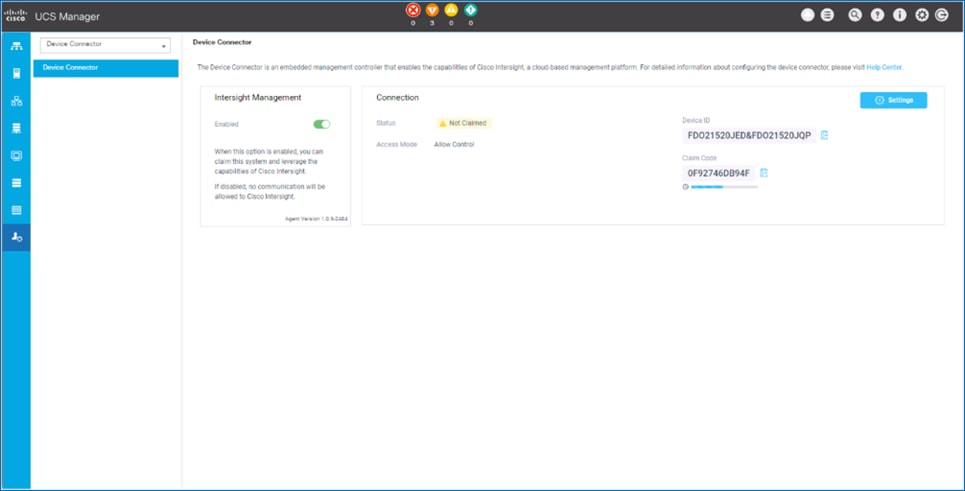
5. From the Connection section, copy the Device ID and Claim ID information. This information will be required to add this device to Cisco Intersight.
6. (Optional) Click Settings to change Access Mode and to configure HTTPS Proxy.
Add Cisco UCS Domain to Cisco Intersight
To add Cisco UCS Fabric Interconnects to Cisco Intersight to manage the UCS domain, follow these steps:
1. From Cisco Intersight, in the left navigation menu, select Devices.
2. Click the Claim a New Device button in the top right-hand corner.
3. In the Claim a New Device pop-up window, paste the Device ID and Claim Code collected in the previous section.
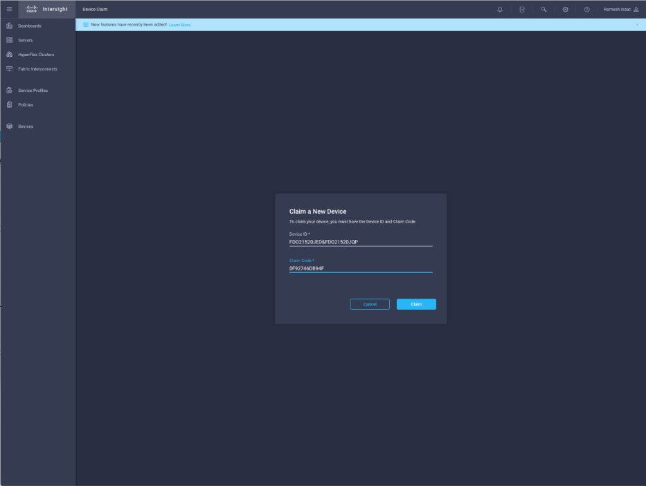
4. Click Claim.
5. On Cisco Intersight, the newly added UCS domain should now have a Status of Connected.
6. On Cisco UCS Manager, the Device Connector should now have a Status of Claimed.
7. Dashboard will present an overview of the managed UCS domains:
Shailendra Mruthunjaya, Cisco Systems, Inc.
Shailendra is a Technical Marketing Engineer with Cisco UCS Solutions and Performance Group. Shailendra has over eight years of experience with SAP HANA on Cisco UCS platform. Shailendra has designed several SAP landscapes in public and private cloud environment. Currently, his focus is on developing and validating infrastructure best practices for SAP applications on Cisco UCS Servers, Cisco Nexus products and Storage technologies.
Dr. Stephan Kreitz, Hitachi Vantara
Stephan Kreitz is a Master Solutions Architect in the Hitachi Vantara Converged Product Engineering Group. Stephan has worked at SAP and in the SAP space for Hitachi Vantara since 2011. He started his career in the SAP space as a Quality specialist at SAP and has worked in multiple roles around SAP at Hitachi Data Systems and Hitachi Vantara. He is currently leading the virtualized SAP HANA solutions at Hitachi Vantara, responsible for Hitachi Vantara’s certifications around SAP and SAP HANA and the technical relationship between Hitachi Vantara and SAP.
Acknowledgements
For their support and contribution to the design, validation, and creation of this Cisco Validated Design, the authors would like to thank:
· Caela Dehaven, Cisco Systems, Inc.
· Erik Lillestolen, Cisco Systems, Inc.
· Pramod Ramamurthy, Cisco Systems, Inc.
· Michael Lang, Cisco Systems, Inc.
· Ramesh Isaac, Cisco Systems, Inc.
· Joerg Wolters, Cisco Systems, Inc.
· YC Chu, Hitachi Vantara
· Tim Darnell, Hitachi Vantara
· Markus Berg, Hitachi Vantara
· Maximilian Weiss, Hitachi Vantara
 Feedback