Connector Specifications
10/100/1000/2500 Ports
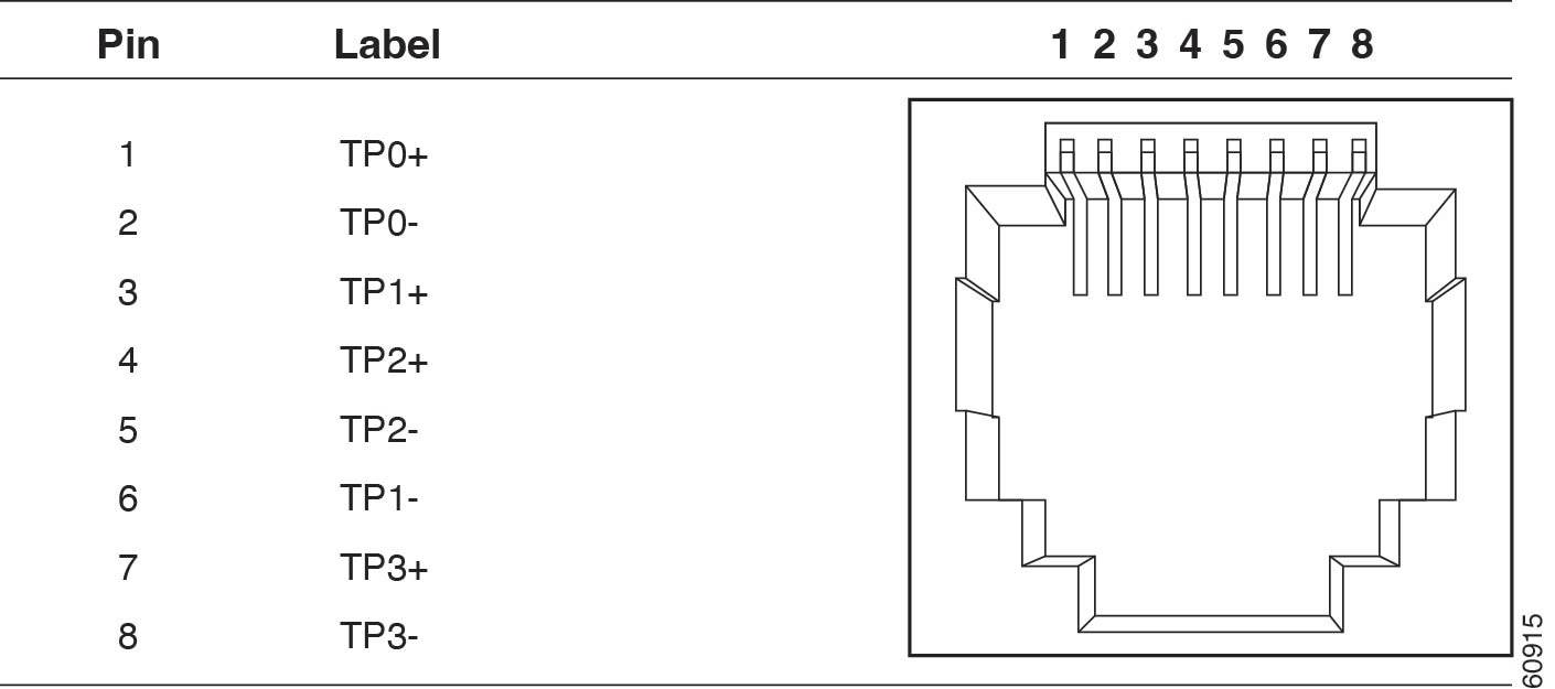
The 10/100/1000 Ethernet ports on the switches use RJ-45 connectors.
 Note |
Connector pins 1, 2, 3, and 6 are used for PoE. |
SFP Module Connectors
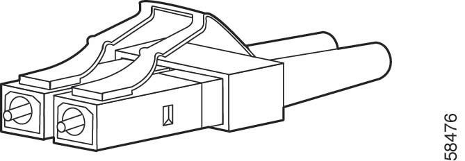
The illustration below shows an LC style connector that is used with the SFP Module slots. It is a fiber-optic cable connector.
 Warning |
Invisible laser radiation may be emitted from disconnected fibers or connectors. Do not stare into beams or view directly with optical instruments. Statement 1051 Avertissement : Les fibres ou les connecteurs déconnectés peuvent émettre des rayonnements laser invisibles. Ne fixez pas les rayons ou ne les regardez pas directement avec des instruments optiques. Énoncé 1051 |
Console Port
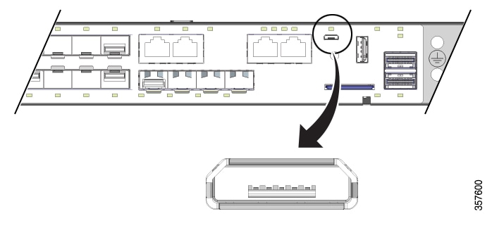
The switch has two console ports: a USB micro-Type B port and an RJ-45 console port, both on the front panel.
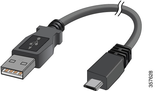
The USB console port uses a USB Type B to 5-pin mini-Type B cable, shown in the following illustration. The USB micro Type A-to-USB mini-Type B cable is not supplied.
Note |
When running Linux, access the USB Console using Minicom instead of Screen . |
The RJ-45 console port uses an 8-pin RJ-45 connector. The supplied RJ-45-to-DB-9 adapter cable is used to connect the console port of the switch to a console PC.
Alarm Port
The alarm port uses an RJ-45 connector.
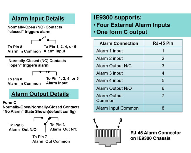
See the sections Alarms and Alarm Ratings for more information.
 Feedback