Switch Installation

Preparing for Installation

Before you install a Cisco Catalyst IE9300 Rugged Series Switch, you must read, understand, and observe the warnings and guidelines in this section. You also must verify the switch package contents, gather the required tools and equipment, and verify the switch operations.

Warnings

These warnings are translated into several languages in the Regulatory Compliance and Safety Information for Cisco Catalyst IE9300 Rugged Series Switch. They apply to all the switch models.


Warning


Statement 1074—Comply with Local and National Electrical Codes

To reduce risk of electric shock or fire, installation of the equipment must comply with local and national electrical codes.


Warning


Statement 1017—Restricted Area

This unit is intended for installation in restricted access areas. Only skilled, instructed, or qualified personnel can access a restricted access area.


Warning


Statement 1024—Ground Conductor

This equipment must be grounded. To reduce the risk of electric shock, never defeat the ground conductor or operate the equipment in the absence of a suitably installed ground conductor. Contact the appropriate electrical inspection authority or an electrician if you are uncertain that suitable grounding is available.


Warning


Statement 1028—More Than One Power Supply

This unit might have more than one power supply connection. To reduce risk of electric shock, remove all connections to de-energize the unit.


Warning


Statement 9001—Product Disposal

Ultimate disposal of this product should be handled according to all national laws and regulations.


Installation Guidelines

Before installing the Cisco Catalyst IE9300 Rugged Series Switch, be sure to meet the following guidelines:

  • Ensure that cabling is away from sources of electrical noise, such as radios, power lines, and fluorescent lighting fixtures. Also ensure that the cabling is away from other devices that might damage the cables.

  • Ensure that the operating environment is within the ranges that are listed in Technical Specifications.

  • Ensure that relative humidity around the switch does not exceed 95 percent (noncondensing).

  • Ensure that the altitude at the installation site is no higher than 15,000 feet (4572 m).

  • For 10/100/1000 fixed ports, ensure that cable lengths from the switch to connected devices are not more than 328 feet (100 meters).

  • For more information about SFP/SFP+ modules and cables, see Transceiver Modules.

  • Ensure that airflow around the switch and through the vents is unrestricted. To prevent overheating, the switch must meet the minimum clearance of 1.75 in. (4.4 cm) at the top, bottom, and sides.


    Note


    If the switch is installed in a closed or multirack assembly, the temperature around it might be greater than normal room temperature. Ensure that the internal temperature does not exceed the maximum ambient temperature specifications for the switch.


Required Tools and Equipment

Obtain the necessary tools and equipment:

  • Phillips screwdriver

Verifying the Package Contents

The shipping box contains the model of the switch you ordered and other components that you need for installation. Some components are optional, depending on your order.


Note


Verify that you have received these items. If any item is missing or damaged, contact your Cisco representative or reseller for instructions.


Verifying the Switch Operation

Before installing the switch in a rack or on a wall, you should power the switch and verify that the switch passes the power-on self-test (POST).

To wire the switch to the power source, see Power-Supply Module Installation.

When the switch begins POST, the SYS LED blinks green, and the other LEDs stay green. When the switch passes POST, the SYS LED turns green. The other LEDs turn off and return to their operating status. If the switch fails POST, the SYS LED is red.


Note


Contact Cisco Systems immediately if your switch fails POST.


After a successful POST, disconnect the power from the switch. For more information, see Wiring the Power Source. See the Installing the Switch to install the switch in a rack or on a wall.
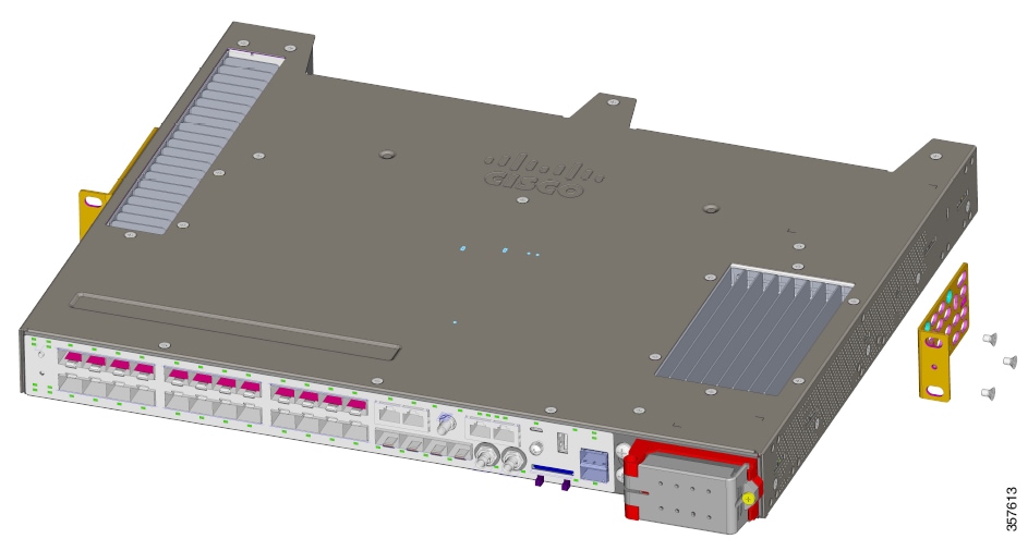
Switch Installation

You can install the Cisco Catalyst IE9300 Rugged Series Switch in a 19-inch, 23-inch, or ETSI rack or on a wall. Follow the instructions in the appropriate section.

Rack-Mount Installation

To rack-mount the switch, select the rack size and follow the steps in these sections:


Warning


To prevent bodily injury when mounting or servicing this unit in a rack, you must take special precautions to ensure that the system remains stable. Observe the following guidelines to ensure your safety:

  • Mount the unit at the bottom of the rack if it is the only unit in the rack.

  • When mounting this unit in a partially filled rack, load the rack from the bottom to the top with the heaviest component at the bottom of the rack.

  • If the rack is provided with stabilizing devices, install the stabilizers before mounting or servicing the unit in the rack. Statement 1006

Avertissement :

Pour éviter des blessures corporelles lors du montage ou de l’entretien de l’appareil dans un bâti, vous devez prendre des précautions particulières afin de garantir la stabilité du système. Suivez les directives suivantes pour assurer votre sécurité :

  • S’il n’y a qu’une unité, elle doit être installée au bas du bâti.

  • Si vous montez l’appareil sur un bâti partiellement rempli, chargez le bâti du bas vers le haut en plaçant le composant le plus lourd en bas du bâti.

  • Si le bâti est équipé de dispositifs de stabilisation, installez les stabilisateurs avant de monter l’unité sur le bâti ou d’effectuer son entretien. Énoncé 1006


Statement 1095—Install Switch in a Rack Mid-Mounting Position Only


Warning


Statement 1095—Install Switch in a Rack Mid-Mounting Position Only

For mounting railway-application equipment and for EN50155 standard compliance, the switch must be installed only in a rack mid-mounting position. If you install the switch in a front rack-mounting (cable side or power supply side) position or in a wall-mounting position, a mechanical failure can occur that results in the switch becoming detached from the rack.


Attach Brackets for 19-Inch Racks

Before you begin

Complete the tasks in the section Preparing for Installation.

Procedure

Step 1

Decide whether you will use a front, middle, or rear mounting of the switch in the rack.

Step 2

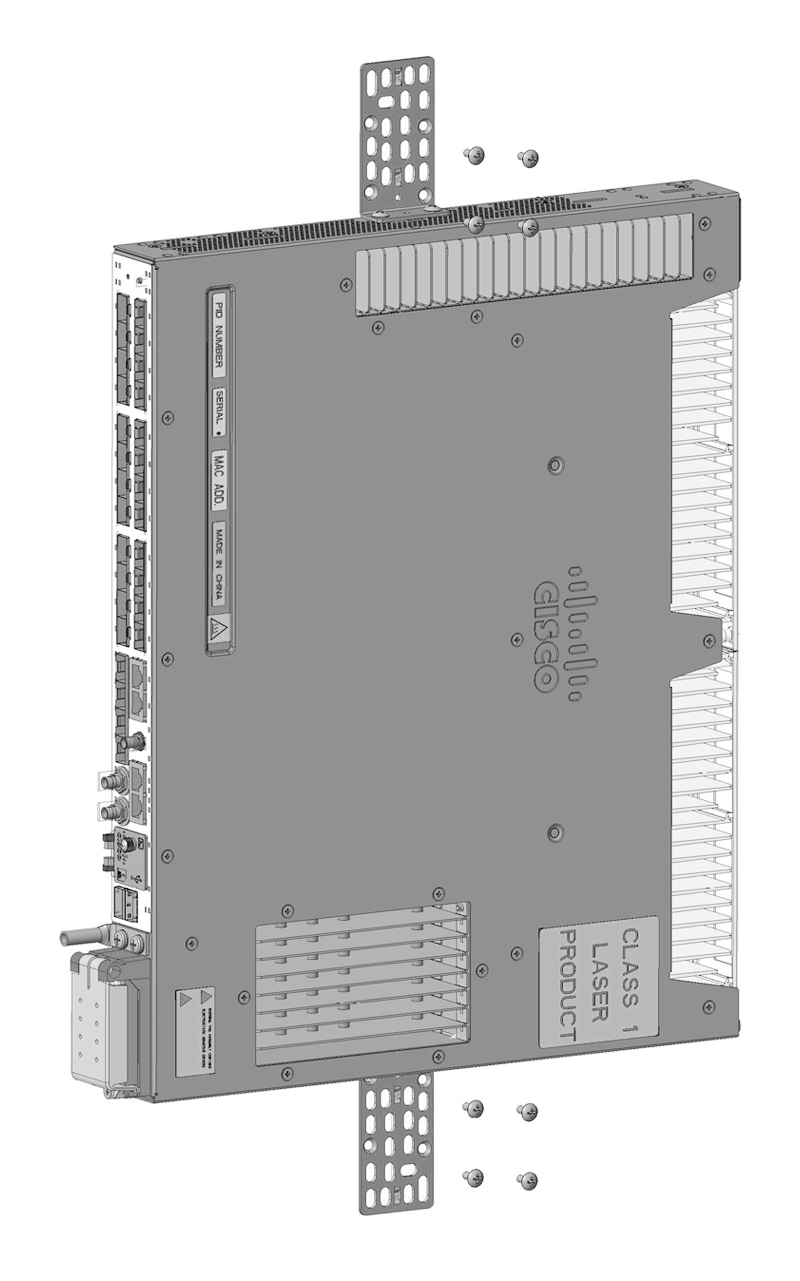
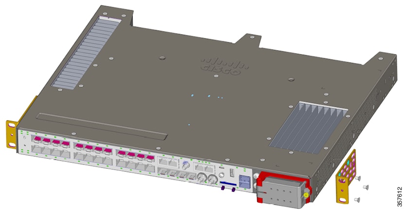
Attach the brackets to the switches, following the steps in the appropriate illustrations.

Figure 1. Attaching Brackets: Front Mounting

Attaching brackets with front mounting
Figure 2. Attaching Brackets: Middle Mounting

Attaching brackets using midmounting

Figure 3. Attaching Brackets: Rear Mounting

Attaching brackets using rear mounting


What to do next

Complete the steps in the section Rack-Mount the Switch.

Install Hole Plugs for IP-30 Compliance (Optional)

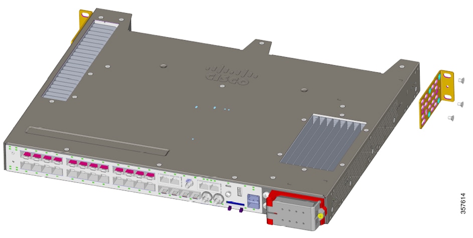
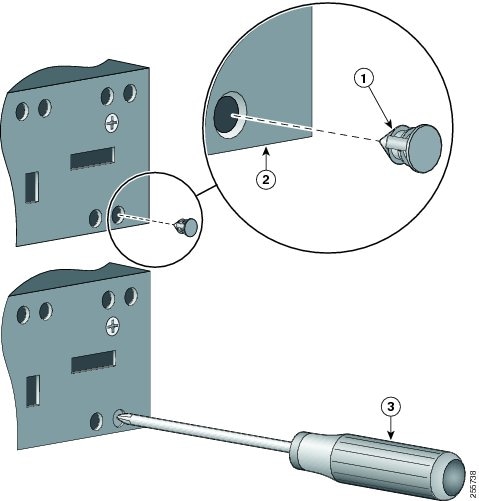
Before installing the mounting brackets, install the rubber plugs in the unused mounting holes. The following figure shows a close-up of the rubber plugs and how to install the rubber plugs in the holes.

Figure 4. Inserting a Rubber Plug
Inserting a rubber plug

1

Rubber plug

3

Screwdriver

2

Switch


Note


If you use 23-inch brackets or ETSI brackets, you can insert the rubber plugs for IP-30 compliance. Before installing the 23-inch or ETSI brackets, insert the rubber plugs in the same holes as shown in this section.


Procedure

Step 1

Identify your bracket mounting position.

Step 2

Install the brackets on both sides of the switch, as described in the section Attach Brackets for 19-Inch Racks.

Step 3

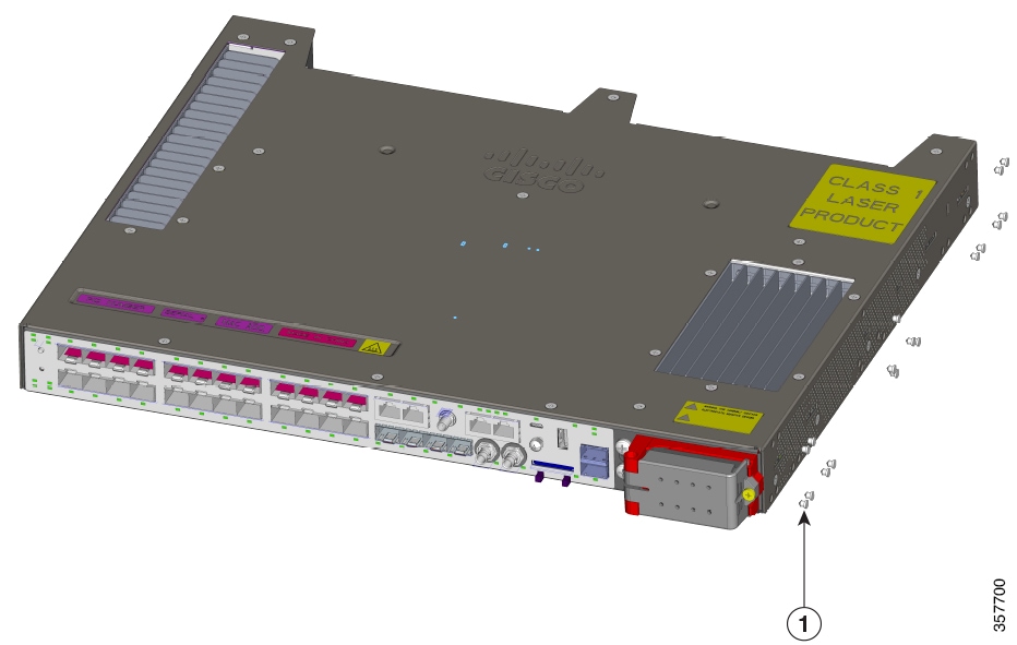
Note the holes on the switch that you will not use for mounting.

The following illustration shows the location of holes on the switch.

Figure 5. Switch Hole Locations


1

Rubber plug

Step 4

Insert the rubber plugs in the appropriate holes on both sides of the switch, as shown in the first illustration in this section.

Step 5

Use a screwdriver or pen to push in the rubber plugs completely.


What to do next

Complete the steps in the section Rack-Mount the Switch.

Attach Brackets for 23-Inch Racks

Follow the instructions in this section to attach 23-inch brackets (RM-RGD-23IN=).


Note


23-inch and ETSI brackets should not be used in high vibration environments, including any railway application (EN50155).


Note


For IP-30 compliance, insert rubber plugs in the same holes as described in the section Install Hole Plugs for IP-30 Compliance (Optional). Do so before installing the brackets.


Before you begin

Complete the tasks in the section Preparing for Installation.

Procedure

Attach the brackets to the switch, as shown in one of the illustrations.

Figure 6. Attaching Brackets for 23-inch Racks (Front Mounting)

Attaching brackets for 23-inch racks, front mounting
Figure 7. Attaching Brackets for 23-inch Racks (Middle Mounting)

Attaching brackets for 23-inch racks, middle mounting

What to do next

Complete the steps in the section Rack-Mount the Switch.

Attach Brackets for ETSI Racks

Follow the instructions in this section to attach brackets for ETSI racks.


Note


  • 23-inch and ETSI brackets should not be used in high vibration environments, including any railway application (EN50155).

  • If you use ETSI brackets you can insert rubber plugs into switch holes for IP-30 compliance. Insert them into the same holes as shown in the image Plug Locations by Position in the section Install Hole Plugs for IP-30 Compliance (Optional). Do so before installing the brackets.


Before you begin

Complete the tasks in the section Preparing for Installation.

Procedure

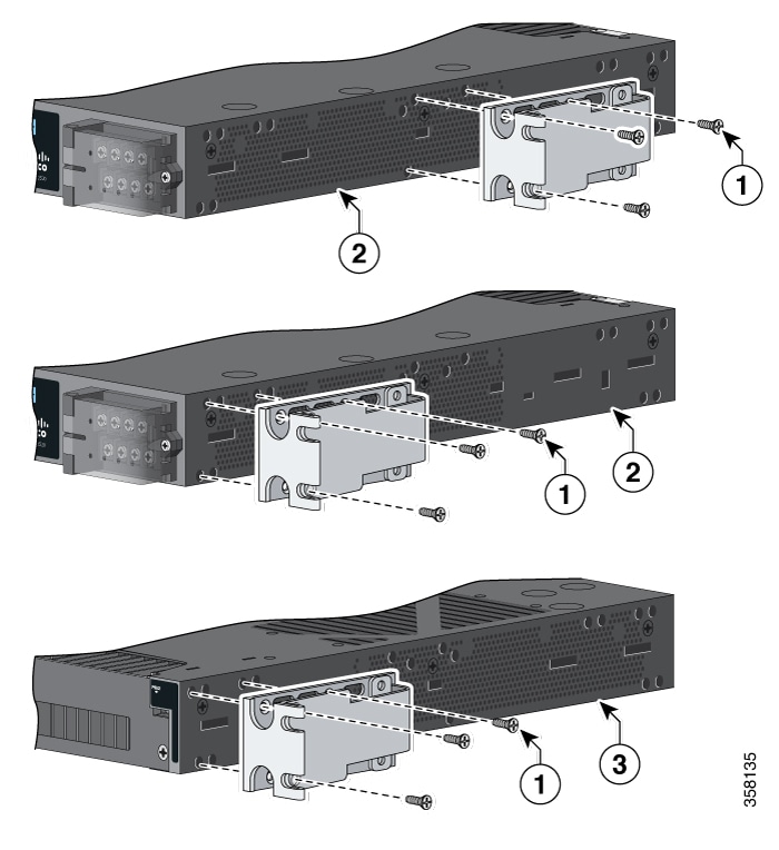
Attach the brackets to the switch, following the steps in the illustration.

Note


In the illustration, mountings are shown as follows: top image, middle mounting; center image, front mounting; bottom image, rear rounting.

Figure 8. Attaching Brackets (RM-RGD-ETSI=) for ETSI Racks


1

Phillips flat-head screws

3

Power-supply-side mounting position

2

Cable-side mounting position


What to do next

Complete the steps in the section Rack-Mount the Switch.

Rack-Mount the Switch

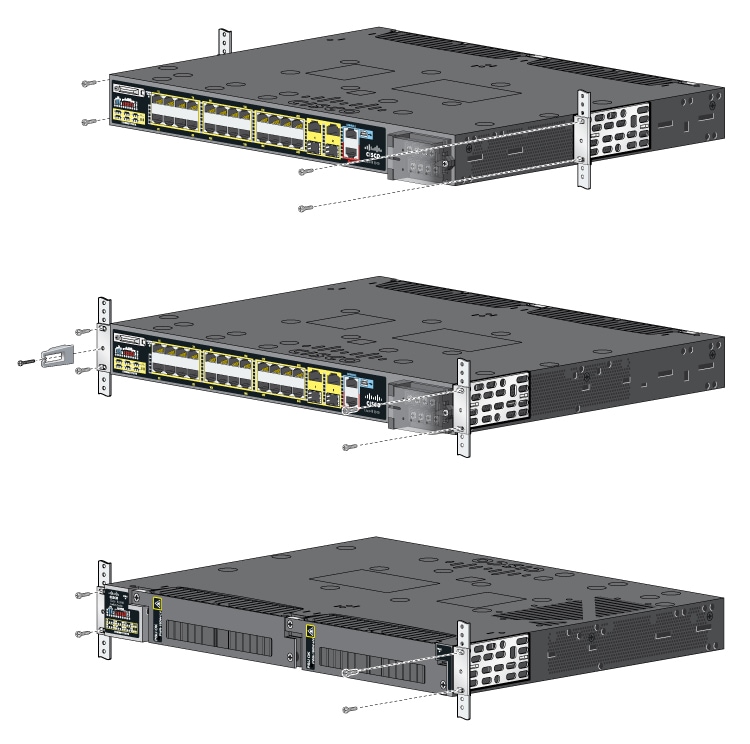
After you attach the brackets on the switch, attach the brackets to the rack, using the following illustrations and steps. The illustration displays, from top to bottom, midrack mounting, front mounting, and rear mounting.

Figure 9. Rack-Mounting the Switch

Rack-mounting the switch


Note


The preceding illustration shows rack mounting for a representative IE switch, but the mounting is the same as for Cisco Catalyst IE9300 Rugged Series Switches.


Before you begin

Attach the brackets to the rack, following instructions in one of the following sections:


Warning


For mounting railway-application equipment and for EN50155 standard compliance, the switch must be installed only in a rack midmounting position. If you install the switch in a front rack-mounting (cable side or power supply side) position or in a wall-mounting position, a mechanical failure can occur that results in the switch becoming detached from the rack. Statement 403

Avertissement :

Pour le montage de l’équipement d’application ferroviaire et pour la conformité à la norme EN50155, le commutateur ne doit être installé que dans une position de montage au milieu du bâti. Si vous installez le commutateur en position de montage en bâti à l’avant (côté câble ou alimentation) ou en position de montage mural, une défaillance mécanique peut se produire et entraîner le détachement du commutateur du bâti. Énoncé 403


Note


If you want to mount the switch to a wall, follow instructions in the section Wall-Mount the Switch.


Procedure

Step 1

Use the illustration to install the switch in the rack.

Step 2

Wire the switch to a power source, following instructions in the section Wiring the Power Source.

Step 3

Attach the cable guide to prevent the cables from obscuring the LED panels on the devices in the rack.

Use the supplied black screw to attach the cable guide to the left or right bracket.


What to do next

Installing Multiple Switches in the Rack

You can mount two Cisco Catalyst IE9320 switches in 19-inch, 23-inch, or ETSI racks. To install each switch, follow the instructions for the appropriate rack earlier in this chapter.

You can also mount two IE9320 switches in a rack and connect them with a stacking cable. The connection enables you to treat multiple switches as if they were one.


Note


For detailed information about electronically stacking switches, see the Stacking and High Availability Configuration Guide, Cisco Catalyst IE9300 Rugged Series Switches on Cisco.com.


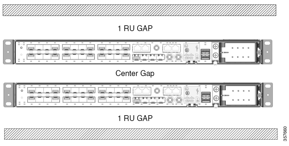
When you mount multiple switches in a rack, you must install the switches with the correct clearances, as shown in the following illustration and table.

When you mount switches in the rack, ensure that there is 1 RU (1.75 in) above the top switch and 1 RU below the bottom switch. The space in the center gap can vary. However, note in the following table that temperature derating for the top switch occurs when using IE9320 GE Fiber switches.

Figure 10. Two Switches Mounted in a Rack

Two switches in rack
Table 1. Clearances for Rack-Mounting Cisco Catalyst IE9300 Rugged Series Switches

Switch Model

Center Gap

Temperature Derating: Top Unit

IE9310 GE Fiber (IE-9310-26S2C)

1 RU

No derating

1/2 RU

No derating

0 RU

No derating

IE9320 GE Fiber (IE-9320-26S2C)

1 RU

2°C derating

1/2 RU

4°C derating

0 RU

8°C derating

IE9320 Fiber switch with 10 GE uplinks (IE-9320-22S2C4X)

1 RU

2°C derating

1/2 RU

4°C derating

0 RU

8°C derating

IE9320 10 GE Copper Data switch (IE-9320-24T4X)

1 RU

No derating

1/2 RU

No derating

0 RU

5°C derating

IE9320 10 GE PoE switch (IE-9320-24P4X)

1 RU

No derating

1/2 RU

No derating

0 RU

5°C derating

IE9320 10 G mGig 4PPoE switch (IE-9320-16P8U4X)

1 RU

No derating

1/2 RU

No derating

0 RU

8°C derating

IE9320 GE PoE (IE-9320-24P4S)

1 RU

No derating

1/2 RU

No derating

0 RU

5°C derating


Note


The temperature derating for the top unit applies to the entire stack.


Wall-Mount Installation

To wall-mount the switch, follow the steps in these sections:


Warning


Read the wall-mounting instructions carefully before beginning installation. Failure to use the correct hardware or to follow the correct procedures could result in a hazardous situation to people and damage to the system. Statement 378

Avertissement :

Lisez attentivement les instructions de montage mural avant de commencer l’installation. Ne pas utiliser le bon matériel ou ne pas suivre les procédures appropriées peut entraîner une situation dangereuse pour les personnes et endommager le système. Énoncé 378


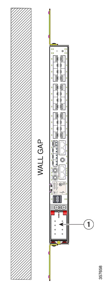
You can mount the switch flush to the wall or 0.75 in away from the wall, as shown in the following illustration and table.

Figure 11. Wall-Mount Clearance

Wall-mount clearance

1

AC/DC power input

Table 2. Clearances for Wall-Mounting Cisco Catalyst IE9300 Rugged Series Switches

Switch

Wall Gap

Temperature Derating

IE9310 GE Fiber (IE-9310-26S2C-A and IE-9310-26S2C-E)

0.75 in

No derating

Flush

No derating

IE9320 GE Fiber (IE-9320-26S2C-A and IE-9320-26S2C-E)

0.75 in

No derating

Flush

5°C derating

IE9320 Fiber with 10 G uplinks

(IE-9320-22S2C4X-A and IE-9320-22S2C4X-E)

0.75 in

No derating

Flush

5°C derating

IE9320 10 GE Copper Data switches (IE-9320-24T4X-A and IE-9320-24T4X-E)

0.75 in

No derating

Flush

5°C derating

IE9320 10 GE PoE switch (IE-9320-24P4X-A and IE-9320-24P4X-E)

0.75 in

No derating

Flush

5°C derating

IE9320 10 G mGig 4PPoE switch (IE-9320-16P8U4X-A and IE-9320-16P8U4X-E)

0.75 in

No derating

Flush

5°C derating

IE9320 GE PoE (IE-9320-24P4S-A and IE-9320-24P4S-E)

0.75 in

No derating

Flush

5°C derating


Warning


For mounting railway-application equipment and for EN50155 standard compliance, the switch must be installed only in a rack mid-mounting position. If you install the switch in a front rack-mounting (cable side or power supply side) position or in a wall-mounting position, a mechanical failure can occur that results in the switch becoming detached from the rack. Statement 403

Avertissement :

Pour le montage de l’équipement d’application ferroviaire et pour la conformité à la norme EN50155, le commutateur ne doit être installé que dans une position de montage au milieu du bâti. Si vous installez le commutateur en position de montage en bâti à l’avant (côté câble ou alimentation) ou en position de montage mural, une défaillance mécanique peut se produire et entraîner le détachement du commutateur du bâti. Énoncé 403


The following minimum clearances apply when mounting the switch vertically in an enclosure:

  • Sides of switch (facing up and facing down): 3.75 in (9.52 cm)

  • Port side 3.0 in (7.62 cm)

  • Power supply side: 5.25 in (13.33 cm)

  • Cover side (not facing wall): 1.75 in (4.44 cm)

  • Base side (facing wall): See the preceding table, Clearances for Wall-Mounting Cisco Catalyst IE9300 Rugged Series Switches. The wall gap depends on the switch model.

Attach Wall-Mount Brackets

Attach the brackets to the switch so that you can attach it to a wall.

Procedure

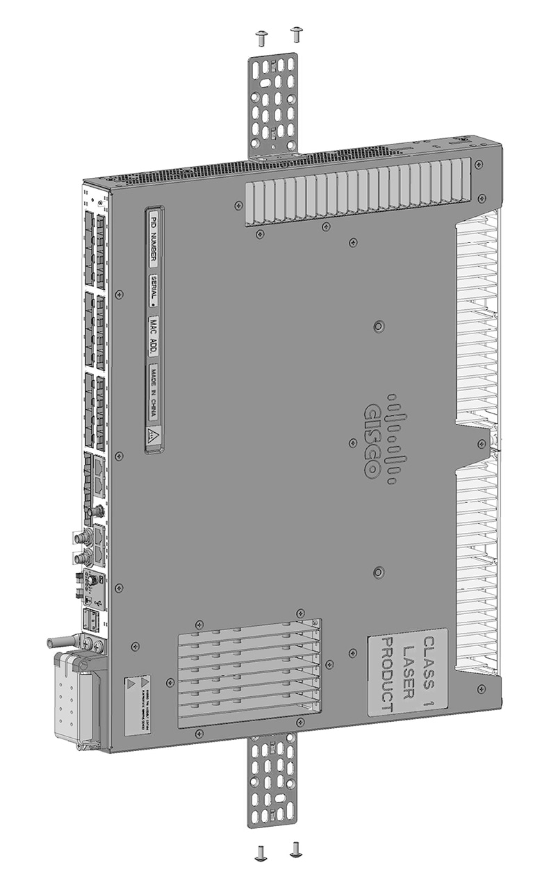
Attach the switch to the wall, as shown in the following illustration:

Figure 12. Attahing the Brackets for Wall Mounting

Attaching the wall-mounting brackets

Note


Only wall-mounting with the power terminal block in the down position is supported.


What to do next

Follow instructions in the section Wall-Mount the Switch.

Wall-Mount the Switch

For the best support of the switch and cables, ensure that the switch is attached securely to wall studs or to a firmly attached mounting backboard.

Orientation should exactly match the following figure, with the embossed Cisco logo facing away from the wall.

Before you begin

Complete the tasks in the section Preparing for Installation.

Procedure

Install the switch, following the orientation in the following illustration:

Figure 13. Wall-mounting the Switch

Wall-mounting the switch

Note


Only wall-mounting with the power terminal block in the down position is supported.


What to do next

Complete the following tasks:

SFP Installation

This section presents procedures to install and remove fiber-optic and 1000BASE-T SFP transceiver modules.

SFP modules are inserted into SFP module slots on the front of the switch.

You can use any combination of rugged SFP modules. Each SFP module must be of the same type as the SFP module on the other end of the cable, and the cable must not exceed the stipulated cable length for reliable communications.

SFP Installation Considerations and Guidelines

Observe the following guidelines when installing SFP modules in the switch.

General Guidelines

Removing and installing an SFP module can shorten its useful life. Do not remove and insert any module more often than absolutely necessary.


Caution


To prevent electrostatic-discharge (ESD) damage, follow standard board and component handling procedures.

Attention :

Pour éviter les dommages causés par les décharges électrostatiques (ESD), suivez les procédures standard de manipulation de la carte et des composants.


Caution


Do not install or remove the SFP module with fiber-optic cables attached. Doing so could result in damage to the cables, the cable connector, or the optical interfaces in the SFP module. Disconnect all cables before removing or installing an SFP module.

Attention :

Ne pas installer ni retirer le module SFP lorsque des câbles à fibre optique sont branchés. Cela pourrait endommager les câbles, le connecteur de câble ou les interfaces optiques du module SFP. Avant le retrait ou l’installation d’un module SFP, déconnectez tous les câbles.


Power Guidelines


Caution


The uplink SFP and SFP+ ports support up to 4 W of total SFP power. Most SFP modules draw 1 W or less and allow use of all four SFP uplinks. When installing higher power modules, ensure that the total rated power draw remains below 4 W. When installing modules that draw higher than 1 W, leave at least one empty slot between them.

Attention :

Les ports de liaison ascendante SFP et SFP+ prennent en charge jusqu’à 4 W d’alimentation SFP totale. La plupart des modules SFP consomment 1 W ou moins et permettent l’utilisation des quatre liaisons ascendantes SFP. Lors de l’installation de modules d’alimentation de plus grande puissance, assurez-vous que la puissance nominale totale reste inférieure à 4 W. Lors de l’installation de modules dont la consommation est supérieure à 1 W, laissez au moins un logement vide entre eux.


Temperature Considerations

Some SFP modules are not rated to work at very low temperatures.


Caution


Depending on the SFP module you use, the operating temperature limits may be affected. Choose an SFP module appropriate to the installed environment. For a complete list of supported SFP modules, see the Cisco Catalyst IE9300 Rugged Series Data Sheet on Cisco.com.

Attention :

Selon le module SFP utilisé, les limites de température de fonctionnement peuvent être affectées. Sélectionnez un module SFP approprié à l’environnement où il est installé. Pour obtenir une liste complète des modules SFP pris en charge, consultez la fiche technique des commutateurs robustes de la gamme Cisco Catalyst IE9300 sur Cisco.com.


Install Fiber Optic SFP Modules

Complete the steps in this section to install and cable an optical SFP transceiver uplink port. Refer to the illustration in the section Front Panel.


Warning


Statement 1008—Class 1 Laser Product

This product is a Class 1 laser product.


Warning


Do not remove the dust plugs from the fiber-optic SFP module port or the rubber caps from the fiber-optic cable until you are ready to connect the cable. The plugs and caps protect the SFP module ports and cables from contamination and ambient light.

Avertissement :

Ne retirez pas les bouchons antipoussière du port du module SFP de fibre optique ni les capuchons en caoutchouc du câble à fibre optique avant d’être prêt à connecter le câble. Les bouchons et capuchons protègent les ports et les câbles du module SPF contre la contamination et la lumière ambiante.


Procedure


Step 1

Attach an ESD-preventive wrist strap to your wrist and to a bare metal surface.

Step 2

Find the send (TX) and receive (RX) markings on the module top.

On some SFP modules, the send and receive (TX and RX) markings might be replaced by arrows that show the direction of the connection, either send or receive (TX or RX).

Step 3

If the module has a bale-clasp latch, move it to the open, unlocked position.

Step 4

Align the module in front of the slot opening, and push until you feel the connector snap into place, as shown in the preceding illustration.

Step 5

If the module has a bale-clasp latch, close it.

Step 6

For fiber-optic SFP modules, remove the dust plugs and save.

Step 7

Connect the SFP cables.


Install 100/1000BASE-T SFP Modules

To install a 100/1000BASE-T SFP transceiver, read the guidance and complete the steps in this section.

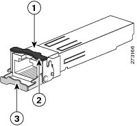
The 100/1000BASE-T (copper) SFP transceiver, shown in the following illustration, has a bale-clasp locking mechanism that secures the transceiver in the module socket. The SFP network interface is an RJ-45 connector.


Caution


To comply with secondary lightning immunity requirements, you must use grounded, shielded, twisted-pair CAT5 or later cabling.

Attention :

Aux fins de conformité avec les exigences secondaires en matière de protection contre la foudre à l’intérieur des bâtiments, vous devez utiliser un câble à paires torsadées blindé et mis à la terre de catégorie 5 ou supérieure.


Note


When connecting to a 100/1000BASE-T-compatible server, workstation, or router, use four twisted-pair, straight-through CAT5E or later cabling for the SFP transceiver port. When connecting to a 100/1000BASE-T-compatible switch or repeater, use four twisted-pair, crossover CAT5E cabling. We recommend CAT6 for 2.5 Gb ports.


Note


100/1000BASE-T SFPs reduce the accuracy of PTP performance.
Figure 14. 1000BASE-T SFP Transceiver

1000BASE-T SFP transceiver

1

RJ-45 connector

1

Bale-clasp latching mechanism in the closed (locked) position

3

Bale-clasp latching mechanism in the open (unlocked) position

Procedure


Step 1

Attach an ESD-preventive wrist strap to your wrist and to the ESD ground connector on the chassis or to a properly grounded bare metal surface.

Note


To avoid ESD damage, handle the SFP by its sides; do not touch the connector pins.

Step 2

Remove the SFP module from its protective packaging.

Step 3

Check the markings on the SFP transceiver to verify that you have the correct model for your network.

Step 4

Position the SFP transceiver in front of the port socket opening.

Note


Different Cisco devices have different SFP transceiver socket configurations. Your Cisco device might require that the SFP transceiver be installed with the bale-clasp either in a latch-up or a latch-down orientation. Verify that you have the SFP transceiver oriented correctly when you position it in front of the port socket.

Step 5

With the bale-clasp closed (locked), slide the SFP transceiver into the socket until you feel it snap in place in the socket.

You may hear an audible click as the SFP transceiver latch engages in the socket.

Step 6

Connect the network interface cable RJ-45 plug to the SFP RJ-45 connector.

Step 7

Observe the port status LED:

  • Green indicates that the SFP transceiver and the target device established a link.

  • Amber indicates that the port is discovering the network topology and searching for loops.

    This process takes about 30 seconds, and then the LED turns green.

  • Off indicates that the target device might not be turned on, there might be a cable problem, or there might be a problem with the adapter installed in the target device. Refer to Troubleshooting for solutions to cabling problems.


Guidance for Connecting to SFP Modules

Before you connect the switch to SFP modules, read and understand the guidancxe in this section.

Before connecting to the SFP module, be sure that you understand the port and cabling guidelines in Installing and Removing SFP Modules. See Cable and Connectors for information about the LC on the SFP module.


Warning


Statement 1008—Class 1 Laser Product

This product is a Class 1 laser product.


Caution


Do not remove the dust plugs from the fiber-optic SFP module port or the rubber caps from the fiber-optic cable until you are ready to connect the cable. The plugs and caps protect the SFP module ports and cables from contamination and ambient light.

Attention :

Ne retirez pas les bouchons antipoussière du port du module SFP de fibre optique ni les capuchons en caoutchouc du câble à fibre optique avant d’être prêt à connecter le câble. Les bouchons et capuchons protègent les ports et les câbles du module SPF contre la contamination et la lumière ambiante.


Caution


To prevent ESD damage, follow standard board and component handling procedures.

Attention :

Pour éviter les dommages causés par les décharges électrostatiques (ESD), suivez les procédures standard de manipulation de la carte et des composants.


Connect to a Fiber Optic SFP Module

Connect a fiber-optic cable to an SFP module.

Before you begin

Read and understand the section Guidance for Connecting to SFP Modules.

Procedure


Step 1

Remove the rubber plugs from the module port and fiber-optic cable, and store them for future use.

Step 2

Insert one end of the fiber-optic cable into the SFP module port.

Step 3

Insert the other cable end into a fiber-optic receptacle on a target device.

Step 4

Observe the port status LED:

  • The LED turns green when the switch and the target device have an established link.

  • The LED turns amber while the STP discovers the network topology and searches for loops. This process takes about 30 seconds, and then the port LED turns green.

  • If the LED is off, the target device might not be turned on, there might be a cable problem, or there might be a problem with the adapter installed in the target device. See Troubleshooting for solutions to cabling problems.

Step 5

If necessary, reconfigure and restart the switch or the target device.


Connect to a 1000BASE-T SFP Module

Connect a CAT5E or later cable to a 1000BASE-T SFP module. We recommend CAT6 cables for 2.5 Gb ports.


Caution


To prevent ESD damage, follow standard board and component handling procedures.

Attention :

Pour éviter les dommages causés par les décharges électrostatiques (ESD), suivez les procédures standard de manipulation de la carte et des composants.


Before you begin

Read and understand the section Guidance for Connecting to SFP Modules.

Procedure


Step 1

When connecting to servers, workstations, and routers, insert a four twisted-pair, straight-through cable in the RJ-45 connector. When connecting to switches or repeaters, insert a four twisted-pair, crossover cable.

When connecting to a 1000BASE-T device, use a four twisted-pair CAT5E cable. We recommend CAT6 cables for 2.5 Gb ports.

Step 2

Insert the other cable end in an RJ-45 connector on a target device.

Step 3

Observe the port status LED.

  • The LED turns green when the switch and the target device have an established link.

  • The LED turns amber while the STP discovers the network topology and searches for loops. This process takes about 30 seconds, and then the port LED turns green.

  • If the LED is off, the target device might not be turned on, there might be a cable problem, or there might be problem with the adapter installed in the target device. See Troubleshooting for solutions to cabling problems.

Step 4

If necessary, reconfigure and restart the switch or target device.


Remove SFP Modules

Remove an SFP module.

Procedure


Step 1

Attach an ESD-preventive wrist strap to your wrist and to a bare metal surface.

Step 2

Disconnect the cable from the SFP module.

For reattachment, note which cable connector plug is send (TX) and which is receive (RX).

Step 3

Insert a dust plug into the optical ports of the SFP module.

Step 4

If the module has a bale-clasp latch, pull the bale out and down to eject it.

For a view of the latch, see the illustration of the 1000BASE-T SFP transceiver in the section Install 100/1000BASE-T SFP Modules.

If the latch is obstructed and you cannot use your finger, use a small, flat-blade screwdriver or other long, narrow instrument.

Step 5

Grasp the SFP module, and carefully remove it from the slot.

Step 6

Place the module in an antistatic bag or other protective environment.


Replace the SD Flash Memory Card

Procedure


Step 1

Locate the flash memory card slot on the front of the switch.

Step 2

Loosen the captive thumbscrew. (Be careful not to cross-thread or overtighten the thumbscrew.)

Step 3

Pull the cover open, and pull the cover tab from the hinge.

Step 4

Gently push the flash memory card to eject it.

Place it in an antistatic bag to protect it from static discharge.

Step 5

Push the replacement card into the slot, and press it firmly in place.

The card is keyed so that you cannot insert it the wrong way.

Step 6

Place the flash card slot cover tabs into the hinge.

Step 7

Close the cover, and then hand-tighten the screw.


Connecting Devices to the Ethernet Ports

The Ethernet ports use standard RJ-45 connectors with Ethernet pinouts. The maximum cable length is 328 feet (100 meters). The 100BASE-TX and 1000BASE-T traffic requires Category 5, Category 5e, Category 6 UTP, or later cable. The 10BASE-T traffic uses Category 3 or Category 4 cable.


Note


Use shielded Ethernet cables to improve EMI/EMC performance.


The autonegotiation feature is enabled by default on the switch. At this setting, the switch ports configure themselves to operate at the speed of the attached device. If the device does not support autonegotiation, you can set the switch port speed and duplex parameters. To maximize performance, either let the ports autonegotiate both speed and duplex, or set the port speed and duplex parameters on both ends of the connection.

See the switch software configuration guide or the switch command reference on Cisco.com for more information about autonegotiation and auto-MDIX.

For simplified cabling, the automatic medium-dependent interface crossover (auto-MDIX) feature is enabled by default. With auto-MDIX enabled, the switch detects the required cable type for copper Ethernet connections and configures the interface accordingly. Therefore, you can use either a crossover or a straight-through cable for connections to an Ethernet port, regardless of the type of connected device.

If auto-MDIX is disabled, use the guidelines in Cables and Adapters to select the cable for connecting the Ethernet ports to other devices.

When using PoE/PoE+, those ports have the same autonegotiation settings and cabling requirements as those in the Connecting Devices to the Ethernet Ports. These ports provide PoE power.

See the section Cable and Connectors for information on the cables and connectors.

The ports provide PoE/PoE+ support for devices compliant with IEEE 802.3af/at.

On a per-port basis, you can control whether or not a port automatically provides power to a connected PoE powered device (PD).


Caution


Category 5e and Category 6 cables can store high levels of static electricity. Always ground the cables to a suitable and safe earth ground before connecting them to the switch or other devices.

Attention :

Les câbles de catégories 5e et 6 peuvent contenir des niveaux élevés d’électricité statique. Procédez à une mise à la terre adaptée et sûre avant de les connecter au commutateur ou aux autres appareils.