Cisco Catalyst IE9300 Rugged Series Switches

Cisco Catalyst IE9300 Rugged Series Switches

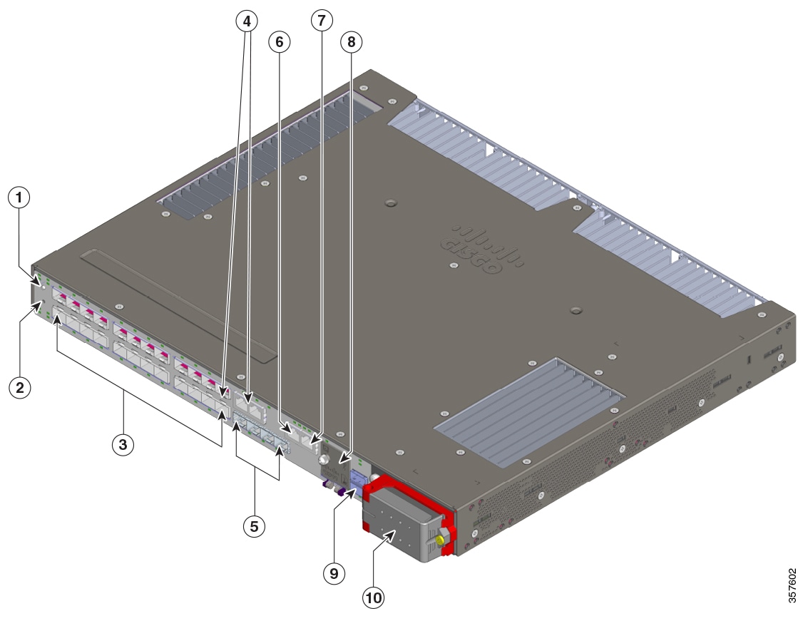
The Cisco Catalyst IE9300 Rugged Series Switch provides rugged and secure switching infrastructure for harsh environments. It is suitable for industrial Ethernet applications, including manufacturing, utility substations, intelligent transportation systems (ITSs), rail transportation, and other similar deployments. Several versions of the switch offer a GNSS receiver, IRIG-B connectors, and PoE.

The switch fulfills the need for a high-density rack-, or wall-mount switch that can function as a software-defined (SD)-Access fabric edge. It provides end-to-end architectural uniformity in the Cisco Digital Network Architecture (DNA) for Internet of Things (IoT) for connected communities and extended enterprise applications.

In industrial environments, the switch can be connected to any Ethernet-enabled industrial communication devices. These devices include programmable logic controllers (PLCs), human-machine interfaces (HMIs), drives, sensors, and input and output (I/O) devices.

Switch Models

The Cisco Catalyst IE9300 Rugged Series Switch is available in several hardware models.

All switches have a total of 28 ports and support two field-replaceable redundant AC or DC power supplies.

Table 1. Cisco Catalyst IE9300 Rugged Series Switch Models

Model

SFP/SFP+ Uplinks

SFP/SFP+ Downlinks

Default Software License

Stacking Support

GNSS and IRIG-B

IE-9310-16P8S4X-A

4x 10 Gb SFP+

16x 1 Gb RJ45 PoE+ and 8x 1G SFP

Network Advantage

No

No

IE-9310-16P8S4X-E

Network Essentials

IE-9310-26S2C-A

4x 1 Gb SFP

22x 1 Gb SFP

2x 1 Gb dual-media ports

Network Advantage

No

No

IE-9310-26S2C-E

Network Essentials

IE-9320-26S2C-A

4x 1 Gb SFP

22x 1 Gb SFP

2x 1 Gb dual-media ports

Network Advantage

Yes

No

IE-9320-26S2C-E

Network Essentials

IE-9320-22S2C4X-A

4x 10 Gb SFP+

22x 1 Gb SFP

2x 1 Gb dual-media ports

Network Advantage

Yes

Yes

IE-9320-22S2C4X-E

Network Essentials

IE-9320-24T4X-A

4x 10 Gb SFP+

24x 1 Gb RJ45

Network Advantage

Yes

No

IE-9320-24T4X-E

Network Essentials

IE-9320-24P4X-A

4x 10 Gb SFP+

24x 1 Gb RJ45 PoE+

Network Advantage

Yes

No

IE-9320-24P4X-E

Network Essentials

IE-9320-16P8U4X-A

4x 10 Gb SFP+

16x 1 Gb RJ45 PoE+

8x 2.5 Gb RJ45 4PPoE (90W/port)

Network Advantage

Yes

No

IE-9320-16P8U4X-E

Network Essentials

IE-9320-24P4S-A

4x 1 Gb SFP

24x 1 Gb RJ45 PoE+

Network Advantage

Yes

No

IE-9320-24P4S-E

Network Essentials


Note


In the preceding table, -A at the end of a model name indicates that the model has a Network Advantage license. An -E indicates that the model has a Network Essentials license. For information about differences between the licenses, see the Cisco Catalyst IE9300 Rugged Series Data Sheet on Cisco.com.


All Cisco Catalyst IE9300 Rugged Series Switch models have 4 GB of DRAM, four alarm inputs, and one alarm output. Other I/O includes the following:

  • SD-card slot

  • Power input

  • RJ-45 (RS-232) console

  • Micro-USB console

  • USB-A host port

The IE9320 10 GE Fiber switch also has a GNSS receiver and IRIG-B time code input/output connectors. For more information, see the section Timing Features in this guide.


Note


  • IE9310 GE Fiber refers to both IE-9310-26S2C-A and IE-9310-26S2C-E switches.

  • IE9320 GE Fiber refers to both IE-9320-26S2C-A and IE-9320-26S2C-E switches.

  • IE9320 Fiber switch with 10 GE uplinks refers to IE-9320-22S2C4X-A and IE-9320-22S2C4X-E switches.

  • IE9320 10 GE Copper Data switch refers to IE-9320-24T4X-A and IE-9320-24T4X-E switches.

  • IE9320 10 GE PoE switch refers to IE-9320-24P4X-A and IE-9320-24P4X-E switches.

  • IE9320 10 G mGig 4PPoE switch refers to IE-9320-16P8U4X-A and IE-9320-16P8U4X-E switches.

  • IE9320 GE PoE switch refers to IE-9320-24P4S-A and IE-9320-24P4S-E switches.


Front Panel

All the ports and LEDs of Cisco Catalyst IE9300 Rugged Series Switches are on the front panel. This section shows the arrangement of features on the front panel; see other sections for detailed information about ports and LEDs.


Note


  • LEDs are distributed over the front panel, each one near the interface it relates to. System status LEDs that are not associated with a specific interface are on the left side of the front panel.

  • The front panels of IE9310 GE Fiber and IE9320 GE Fiber models are nearly identical. Later sections note the few differences.

  • The front panels of IE9320 10 GE models are similar to those of IE9310 GE Fiber and IE9320 GE Fiber models. Later sections note the few differences.

  • The front panels of IE9320 PoE models are similar to those of IE9320 GE Fiber models. Later sections note the few differences.

  • The power supply LEDs are also visible on the rear of the switch, where the power supply units are installed.


Figure 1. Front Panel: IE9310 GE Fiber and IE9320 GE Fiber Switches


1

Display mode button

6

Alarms

2

Express Setup button

7

RJ-45 console port

3

Ethernet SFP downlinks

8

(Beneath cover) Micro-USB console port, USB-A host port, and SD slot

4

Dual-media downlink ports 9

Stacking interface (IE9320 switches only)

5

Ethernet SFP uplinks

10

AC/DC power input


Note


Dual-media downlink ports are sometimes referred to as combination ports or combo ports.


The following image shows the front panel of IE9320 10 GE switches, calling out features not found on other switch model. The other front panel features are the same as on the IE9310 GE Fiber and IE9320 GE Fiber switches.

Display Mode Button

Each Ethernet port has an LED, which displays information about the port. You can control the type of information that the port LEDs display by pressing the display mode button and its LEDs.

The Cisco Catalyst IE9300 Rugged Series Switch has multiple LEDs, one for each different mode. To select or change a mode, press the display mode button until the desired mode LED is lit. When you choose a mode, the disply mode button LED turns solid green, and the port LEDs light up according to the mode. When you change port modes, the meanings of the port LED colors also change. The display mode button LED turns off after 5 seconds or when you choose a different mode.

The IE9310 and IE9320 switches have Speed, Duplex, and Redundancy modes and LEDs. IE9320 switches also have a Stack LED.


Note


The modes apply to SFP and copper ports. Combination ports have two port LEDs, one by the SFP connector and the second by the RJ-45 connector. Only one can be active at a time.

For details about the display modes and corresponding port LEDs, see the section Ethernet Ports in this document.


Express Setup Button

Express Setup is a web-based procedure to configure initial IP address information to the new switch. It provides a simple way to manage the switch and connect it to an existing network of local routers and the internet.

The front panel of the Cisco Catalyst IE9300 Rugged Series Switch has an Express Setup button and a setup LED. The button is recessed to prevent accidental activation; you need a paper clip or similar object to press it. Express Setup has three modes, which you trigger by varying the amount of time that you press the button.

Table 2. Express Setup Modes

Mode

Seconds Required to Trigger Mode

Description

Short Press

1 to 5 seconds

Places the switch into Express Setup mode.

Medium Press

6 to 10 seconds

Causes the switch to start DHCP discovery phase on the Vlan 1 interface.

Long Press

16 to 20

Causes the switch to erase its startup configuration and reload. This in turn causes the switch to revert to its Day 1 default configuration.

The setup LED displays the Express Setup mode for the initial configuration.

Table 3. Setup LED States

Color

Status

Off

Switch is configured as a managed switch.

Solid green

System is operating normally.

Blinking green

Switch is in initial setup, in recovery, or initial setup is incomplete.

Red

Switch failed to start initial setup or recovery because there is no available switch port to connect the management station. Disconnect a device from a switch port, and then press the Express Setup button.

System LED

The system LED provides basic status about the health of the Cisco Catalyst IE9300 Rugged Series Switch.

Table 4. System LED

Color

System Status

Off

System is not powered on.

Blinking green

Power-on self-test (POST) is in progress.

Green

System is operating normally.

Red

System is receiving power but is not functioning properly.

Blinking red

Boot failure.

Power Supplies

The Cisco Catalyst IE9300 Rugged Series Switch supports two hot-swappable, redundant, load-sharing FRU power supplies. It requires one power supply for system operation, and the second power supplies is optional for redundancy. A second power supply can also increase the PoE power budget on switches that support PoE.

Both power supplies are installed on the back of the switch.

Figure 2. Power Supply Units

Power supply units at back of switch

1

Power Supply 1

2

Power Supply 2

The power supply AC/DC power input is on the front of the switch.

Figure 3. Power Supply AC/DC Input

Power supply AC/DC input

Each power supply has its own LED, which shows if the power supply is receiving power and if it is working properly. The LEDs are driven directly by the power supplies and are not under software control. Control by the power supplies ensures that the LEDs turn on when the power is available and remain on regardless of the software state.

For details about the power supply and its LED, see the section Power Supply Modules.

Ethernet Ports

The Cisco Catalyst IE9300 Rugged Series Switch supports four uplink (1 G or 10 G) ports and 24 downlink ports. Two of the downlink ports on fiber switches can function as dual-media downlink ports, providing an SFP interface and a copper interface.

    • IE9310 Mixed port switch: Uplinks support 10 Gb SFPs. Downlink support 1 Gb, 100 Mb, 10 Mb copper and SPFs.

    • IE9310 GE Fiber switches: SFP downlinks support 1 Gb and 100 Mb SFPs; uplinks support 1 Gb SFPs.

    • IE9320 GE Fiber switches: SFP downlinks and uplinks support 1 Gb and 100 Mb SFPs.

    • IE9320 10 GE Fiber switches: SFP downlinks support 1 Gb and 100 Mb SFPs; uplinks support 1 Gb and 10 Gb SFPs.

    • IE9320 GE Copper switches: Uplinks support 1 Gb SFPs. Downlinks support 1 Gb, 100 Mb, 10 Mb.

    • IE9320 10 GE Copper switches: Uplinks support 1 Gb and 10 Gb SFPs. Gigabit downlinks support 1Gb, 100 Mb, 10 Mb, 2.5 Gb downlinks support 2.5 Gb, 1Gb, and 100Mb (full-duplex only).


    Note


    Each port has an LED above or below it.


  • Ethernet dual-media downlink ports: All dual-media downlink ports support 1 Gb and 100 Mb SFPs on the SFP interface. The copper media support 1000BASE-T, 100BASE-TX, and 10BASE-T with autonegotiation, auto-MDIX, and cable diagnostics on an RJ-45 connector. Each dual-media downlink port has two LEDs, one by the SFP connector, and one by the RJ-45 connector.


    Note


    • Only one interface on dual-media downlink ports can be active at a time.

    • GLC-TE Transceiver module or any copper SFP is not supported on dual-media ports.

      We recommend you to use RJ45 interfaces instead of the fiber interfaces for copper connections by configuring the interfaces as media-type rj45.

      You need to configure the interfaces to use RJ45 interfaces instead of the fiber interfaces for copper connections by configuring the interfaces as media-type rj45.

    • Dual-media downlink ports are sometimes referred to as combination ports or combo ports.


Each port LED displays information about its individual port. However, you can use the display mode button to cycle through the different LED modes, which determines the kind of information that is shown by the port LEDs. When you choose a mode, the mode LED lights up solid green, and the port LEDs light up as described in the following table. After 5 seconds, the mode LED turns off, its default state.

Table 5. Ethernet Port LEDs

Port Mode

LED Color

Status

Not illuminated

(Default)

Off

No link, or port that is administratively shut down.

Green

Link present but no activity.

Blinking green

Activity. Port is sending or receiving data.

Alternating green and amber

Link fault. Error frames can affect connectivity, and errors such as excessive collisions, CRC errors, and alignment and jabber errors are monitored for a link fault.

Amber

Port is blocked by Spanning Tree Protocol (STP) and is not forwarding data.

After a port is reconfigured, the port LED can remain amber for up to 30 seconds while STP checks the switch for possible loops.

Blinking amber

System is sending Spanning Tree bridge protocol data units (BPDUs) on an STP blocked port.

SPEED

Off

Port is operating at 10 Mb/s.

Green

Port is operating at 100 Mb/s.

Blinking green

(On for 100 ms., off for 1900 ms.)

Port is operating at 1000 Mb/s.

Blinking green

(On for 200 ms., off for 1800 ms.)

Port is operating at 2500 Mb/s..

Blinking green

(On for 800 ms., off for 1200 ms.)

Port is operating at 10 G.

DUPLEX

Off

Port is operating in half duplex.

Green

Port is operating in full duplex.

REDUNDANCY

Off

Port is not participating in a redundancy protocol.

Green

Port is participating in a redundancy protocol (REP, HSR, PRP, MRP, and so on.)

Blinking amber

Port is participating in a redundancy protocol, and a redundancy fault is present.

STACK

Off

No stack member corresponding to that member number.

Green

Member numbers of other stack member switches.

Blinking green

Stack member number.

PoE

Off

PoE is off. The switch port is not providing power.

Green

PoE is on. The switch port is providing power.

Alternating green and amber

PoE is denied because providing power to the powered device will exceed the switch power capacity.

Blinking amber

PoE is off because of a fault or because it has exceeded a limit set in the switch software.

Amber

PoE+ for the port has been disabled.

Alarms

Each Cisco Catalyst IE9300 Rugged Series Switch has four alarm inputs and one output. You can connect up to four alarm inputs from different devices—such as a cabinet tamper switch or over-temperature sensor—to the alarm port. You can use the CLI to set the alarm severity to minor or major.

The switch software monitors switch conditions for each port or the switch overall. If the conditions present on the switch or a port do not match the set parameters, the switch software triggers an alarm or a system message and turns on an LED.

You can configure the system to respond to alarm input in three different ways, as shown in the following table:

Table 6. Alarm Notification Types

Color

Status

Logging

Logging is the default configuration. It sends the message syslog.

You can use the WebUI or CLI to choose another alarm notification method.

SNMP trap

Configure the SNMP traps on the switch to send the notification to the SNMP server.

External

Configure the switch to trigger an external alarm device by using the alarm relay.

Table 7. Alarm Input LEDs

Color

Status

Off

Alarm is not configured.

Green

Alarm is configured but no alarm detected.

Red

Minor alarm is present.

Blinking red

Major alarm is present.

Table 8. Alarm Output LEDs

Color

Status

Green

Alarm is not present.

Red

Minor alarm condition is present.

Blinking red

Major alarm condition is present.

Console Ports

The Cisco Catalyst IE9300 Rugged Series Switch has two console ports: one RS-232 port with an RJ-45 connector, and one USB port with a micro-USB connector. The USB port is behind a small door on the front panel.

Output from the switch is always sent to both ports, but input is accepted only from one port at a time. The USB console LED shows which console port is in use. If both RS-232 and USB console ports are connected, the USB console port has priority unless the USB console is disabled in the switch configuration.
Figure 4. Micro-USB Connector
Micro-USB connector
Table 9. Console Port LEDs

Color

Status

Off

USB port is inactive. RJ-45 console port is active.

Green

USB port is active. RJ-45 console port is inactive.

SD Card Connector

The Cisco Catalyst IE9300 Rugged Series Switch has a secure digital (SD) card connector. You can use the connector for the Swap Drive feature and to copy files on and off the system. The slot is behind a door on the front panel.

The following table shows the SD card connector states and what they mean.

Table 10. SD Card LED

Color

Status

Off

SD card is not present.

Green

SD card is present and working.

Blinking green

SD card transfer is in progress.

Fast blinking amber

Unsupported SD card is detected.


Caution


Do not install or remove the SD card when an explosive environment may be present.

Attention :

Ne pas installer ni retirer la carte SD dans un environnement présentant un risque d’explosion.


USB Host Port

The Cisco Catalyst IE9300 Rugged Series Switch has a USB-A host port on the front panel. Note that the port is intended only for service operation and not for continuous use.

Table 11. USB Host Port LEDs

Color

Status

Off

No USB device is connected.

Green

A USB device is connected and active.

Blinking amber

An unrecognized USB device is connected.

Stacking Interface

The stacking interface allows a group of IE9320 GE Fiber switches or IE9320 Fiber switches with 10 GE uplinks to act as a single large switch. IE9320 GE Fiber switches have two stack interface connectors, and each connector has its own LEDs.

The stacking interface allows a group of supported switches to act as a single large switch. The following Cisco Catalyst IE9300 Rugged Series Switches support stacking:

  • IE-9320-26S2C-E, IE-9320-22S2C4X-E

  • IE-9320-22S2C4X-E, IE-9320-22S2C4X-A

  • IE-9320-24T4X-E, IE-9320-24T4X-A

  • IE-9320-24P4X-E, IE-9320-24P4X-A

  • IE-9320-16P8U4X-E, IE-9320-16P8U4X-A

  • IE-9320-24P4S-E, IE-9320-24P4S-A

The stacking interface has an LED that shows the status of active and standby managers.

Table 12. Stacking interface LEDs

Color

Status

Off

Switch is a stack member (not the active or standby stack manager).

Green

Switch is the active stack manager or not part of a stack (standalone operation).

Slow blinking green

Switch is the standby stack manager.

Amber

An error occurred during stack manager election, or another type of stack error occurred.

Each of the two stack connectors has an LED that shows the status of that stack link.

Color

Status

Off

Stack link is not established on this port.

Green

Stack link is established on this port.

Blinking green

Activity. Stack port is sending or receiving data.

Amber

Stack fault. Stack communication is not working on this port.

Timing Features

IE9320 GE Fiber (IE-9320-22S2C4X-E and IE-9320-22S2C4X-E) switches have integrated hardware support for external time sources: GNSS antenna and Inter-Range Instrumentation Group (IRIG-B) interfaces. These interfaces are complemented by the network time-distribution protocol Precision Time Protocol (PTP).

GNSS antenna and IRIG-B are supported in Cisco IOS XE Dublin 17.12.x and later releases.

GNSS Antenna

IE9320 GE Fiber (IE-9320-22S2C4X-E and IE-9320-22S2C4X-E) switches have a built-in Global Navigation Satellite System (GNSS) receiver. (GNSS is often referred to as GPS.)

The receiver enables the switch to determine its own location and get an accurate time from a satellite constellation. The switch can then become the source (Grand Master Clock) for time distribution in the network. GNSS capability simplifies network synchronization planning and provides flexibility and resilience in resolving network synchronization issues in a hierarchical network.


Note


For information about GNSS, including guidelines and configuration, see the chapter "Global Navigation Satellite System" in the Precision Time Protocol Configuration Guide, Cisco Catalyst IE9300 Rugged Series Switches.


The following illustration shows the placement of the GNSS receiver on the front panel of IE9320 Fiber switches with 10 GE uplinks. The receiver is circled.

Figure 5. GNSS Receiver


The system has an SMA connector to attach an external GNSS antenna. It can provide current-limited power to power an active (amplified) antenna.

The GNSS receiver supports multiple satellite constellations as shown in the following table.

Band

Frequency

Constellations

L1

1602MHz

1575.42 MHz

GPS, GLONASS, QZSS, Galileo

1561.098 MHz

BeiDou

L5

1176.45 MHz

GPS, QZSS, Galileo, BeiDou, NavIC

The following table shows the behavior of the GNSS LEDs.

LED

Color

System Status

GPS

Off

GNSS is not configured.

Solid Green

Active with satellite fix.

Blinking Green

Attempting to acquire satellite fix.

Blinking Amber

Antenna Fault.

GNSS Antenna Requirements

GNSS RF Input

GNSS input requires a GPS/GNSS receive antenna with built-in low-noise amplifier (LNA) for optimal performance. The LNA amplifies the received satellite signals:

  • To ccompensate for cable loss

  • To increase the signal amplitude to a suitable range for the receiver front-end

    The amplification required is 22dB gain + cable loss + connector loss.

    The recommended range of LNA gain (LNA gain minus all cable and connector losses) at the connector of the receiver input is 22dB to 30dB with a minimum of 20dB and a maximum of 35dB.

  • The GPS/GNSS input on the switch provides 3.3 or 5VDC (software configurable) to the antenna through the same RF connector. The antenna should draw between 10 and 100mA. An antenna that draws less than 10mA may wrongly report and "Antenna Open" fault even though the antenna is operating properly.

Power Input

When deployed in a hazardous environment the antenna shall only use power provided by the RF input from a single switch. No additional power may be supplied to the antenna and associated equipment.


Caution


Supplying additional power, such as with a powered splitter or amplified repeater, may provide enough energy to create an arc that could ignite the explosive atmosphere.

Attention :

L’ajout d’un dispositif d’alimentation électrique, comme un répartiteur électrique ou un répéteur amplifié, peut générer suffisamment d’énergie pour créer un arc qui pourrait enflammer une atmosphère présentant un risque d’explosion.


Surge Protection

The GNSS input has built-in ESD protection. If an outdoor antenna is being connected, additional surge protectionis required to meet the regulations and standards for lightning protection in the countries where the end product is installed.

The lightning protection must be mounted at the place where the antenna cable enters the building. The primary lightning protection must be certified for conducting all potentially dangerous electrical energy to PE (protective earth). Surge arrestors should support DC-pass and be suitable for the GPS/GNSS frequency range with low RF attenuation.


Caution


The antenna terminal should be earthed at the building entrance in accordance with the ANSI/NFPA 70, the National Electrical Code (NEC), in particular Section 820.93, Grounding of Outer Conductive Shield of a Coaxial Cable.

Attention :

La borne de l’antenne doit être mise à la terre à l’entrée du bâtiment conformément à la norme ANSI/NFPA 70 et au National Electrical Code (NEC), en particulier l’article 820.93, « Grounding of Outer Conductive Shield of a Coaxial Cable » (mise à la terre du blindage externe conducteur d’un câble coaxial).


Antenna Sky Visibility

GPS signals require a direct line of sight between antenna and satellite. The antenna should see as much of the sky as possible. Fixed installations require four satellites in view for an initial time fix, while subsequent updates may be possible with fewer satellites.

IRIG Timecode

(IE-9320-22S2C4X-E and IE-9320-22S2C4X-E) switchess have IRIG-B timecode input and output capability. The IRIG-B time protocol is widely used to establish and maintain time synchronization between system devices. It is supported beginning with the Cisco IOS XE 17.12.1 release.


Note


For detailed information about IRIG-B, including configuration information, see the chapter "IRIG Time Code B" in the Precision Time Protocol Configuration Guide, Cisco Catalyst IE9300 Rugged Series Switches.


There are two mini-BNC connectors on the front panel: one for digital timecode, and a second for analog timecode, each of which can be configured separately as input or output. The following illustration shows the two IRIG-B connectors on the front of the switch.

Figure 6. IRIG Timecode Connectors


1

IRIG-B digital timecode connector (mini-BNC connector)

2

IRIG-B analog timecode connector (mini-BNC connector)


Note


You must buy or build cables for IRIG-B connectivity following the IRIG-B standard and switch's specifics. These cables are not provided with the platform.


The following table shows the behavior of IRIG timecode LEDS.

LED

Color

System Status

Analog In

Off

Analog timecode input is not configured.

Solid Green

Analog timecode input is present and operating properly.

Alternating Green and Amber

Analog timecode signal is present with errors.

Blinking Amber

Analog timecode input configured, no signal present.

Analog Out

Off

Analog timecode output is not configured.

Solid Green

Analog timecode output is configured and sending a signal.

Digital In

Off

Digital timecode input is not configured.

Solid Green

Digital timecode input is present and operating properly.

Alternating Green and Amber

Digital timecode signal is present with errors.

Blinking Amber

Digital timecode input configured, no signal present.

Digital Out

Off

Digital timecode output is not configured.

Solid Green

Digital timecode output is configured and sending a signal.