Information About Precision Time Protocol
Precision Time Protocol (PTP) is defined in IEEE 1588 as Precision Clock Synchronization for Networked Measurements and Control Systems, and was developed to synchronize the clocks in packet-based networks that include distributed device clocks of varying precision and stability. PTP is designed specifically for industrial, networked measurement and control systems, and is optimal for use in distributed systems because it requires minimal bandwidth and little processing overhead.
Cisco Catalyst IE3x00 Rugged, IE3400 Heavy Duty, and ESS3300 Series Switches (referred to as the switch in the rest of the document) support PTP.
 Note |
Cisco is moving from the traditional master/slave nomenclature. In this document, the terms grandmaster clock (GMC) or time source and time recipient are used instead. |
Why PTP?
Smart grid power automation applications such as peak-hour billing, virtual power generators, and outage monitoring and management, require extremely precise time accuracy and stability. Timing precision improves network monitoring accuracy and troubleshooting ability.
In addition to providing time accuracy and synchronization, the PTP message-based protocol can be implemented on packet-based networks, such as Ethernet networks. The benefits of using PTP in an Ethernet network include:
-
Low cost and easy setup in existing Ethernet networks
-
Limited bandwidth is required for PTP data packets
Ethernet Switches and Delays
In an Ethernet network, switches provide a full-duplex communication path between network devices. Switches send data packets to packet destinations using address information contained in the packets. When a switch attempts to send multiple packets simultaneously, some of the packets are buffered by the switch so that they are not lost before they are sent. When the buffer is full, the switch delays sending packets. This delay can cause device clocks on the network to lose synchronization with one another.
Additional delays may occur when packets entering a switch are stored in local memory while the switch searches the MAC address table to verify the packet Cyclic Redundancy Check (CRC) fields. This process causes variations in packet-forwarding time latency, and these variations might result in asymmetrical packet-delay times.
Adding PTP to a network compensates for these latency and delay problems by correctly adjusting device clocks so that they stay synchronized with one another. PTP enables network switches to function as PTP devices, including boundary clocks and transparent clocks.
Note |
To learn more about PTP clock devices and their role in a PTP network, see PTP Clocks. |
Message-Based Synchronization
To ensure clock synchronization, PTP requires an accurate measurement of the communication path delay between the time source (grandmaster clock) and the time recipient. PTP sends messages between the time source and the time recipient to determine the delay measurement. Then, PTP measures the exact message transmit and receive times and uses these times to calculate the communication path delay. PTP then adjusts the current time information contained in network data for the calculated delay, resulting in more accurate time information.
This delay measurement principle determines path delay between devices on a network, and the local clocks are adjusted for this delay using a series of messages sent between the time source and the time recipient devices. The one-way delay time is calculated by averaging the path delay of the transmit and receive messages. This calculation assumes a symmetrical communication path. However, switched networks do not necessarily have symmetrical communication paths because of the buffering process.
PTP provides a method—using transparent clocks—to measure and account for the delay in a time-interval field in network timing packets, making the switches temporarily transparent to the time source and the time recipient nodes on a network. An end-to-end transparent clock forwards all the messages in a network in the same way that a switch does.
Note |
The Cisco PTP implementation supports multicast PTP messages only. |
To read a detailed description of synchronization messages, refer to PTP Event Message Sequences. To learn more about how transparent clocks calculate network delays, see PTP Clocks.
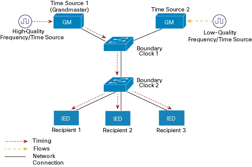
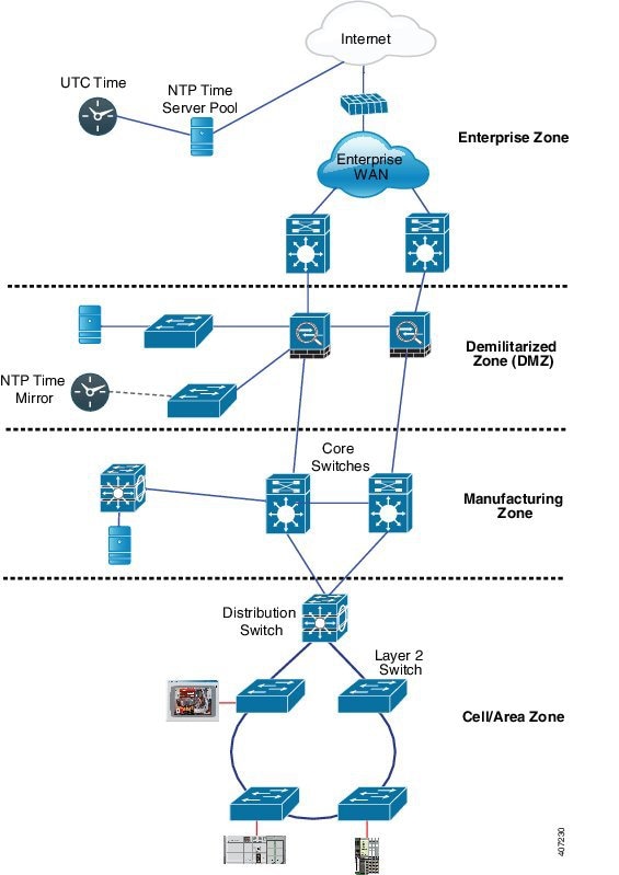
The following figure shows a typical 1588 PTP network that includes time source clocks, switches in boundary clock mode, and intelligent electronic devices (IEDs) such as a digital relays or protection devices. In this figure, Time Source 1 is the grandmaster clock. If Time Source 1 becomes unavailable, the time recipient boundary clocks switch to Time Source 2 for synchronization.
PTP Event Message Sequences
This section describes the PTP event message sequences that occur during synchronization.
Synchronizing with Boundary Clocks
The ordinary clocks and boundary clocks configured for the delay request-response mechanism use the following event messages to generate and communicate timing information:
-
Sync
-
Delay_Req
-
Follow_Up
-
Delay_Resp
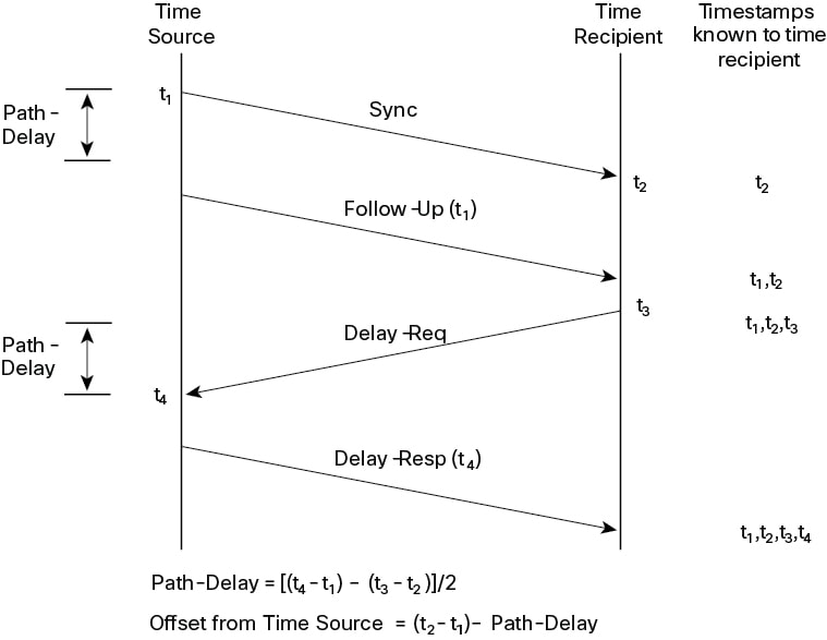
These messages are sent in the following sequence:
-
The time source sends a Sync message to the time recipient and notes the time (t1) at which it was sent.
-
The time recipient receives the Sync message and notes the time of reception (t2).
-
The time source conveys to the time recipient the timestamp t1 by embedding the timestamp t1 in a Follow_Up message.
-
The time recipient sends a Delay_Req message to the time source and notes the time (t3) at which it was sent.
-
The time source receives the Delay_Req message and notes the time of reception (t4).
-
The time source conveys to the time recipient the timestamp t4 by embedding it in a Delay_Resp message.
After this sequence, the time recipient possesses all four timestamps. These timestamps can be used to compute the offset of the time recipient clock relative to the time source, and the mean propagation time of messages between the two clocks.
The offset calculation is based on the assumption that the time for the message to propagate from the time source to the time recipient is the same as the time required from the time recipient to the time source. This assumption is not always valid on an Ethernet network because of asymmetrical packet delay times.
Synchronizing with Peer-to-Peer Transparent Clocks
When a network includes multiple levels of boundary clocks in the hierarchy, with non-PTP-enabled devices between them, synchronization accuracy decreases.
The round-trip time is assumed to be equal to mean_path_delay/2. However, this is not always valid for Ethernet networks. To improve accuracy, the resident time of each intermediary clock is added to the offset in the end-to-end transparent clock. Resident time, however, does not take into consideration the link delay between peers, which is handled by peer-to-peer transparent clocks.
Peer-to-peer transparent clocks measure the link delay between two clock ports implementing the peer delay mechanism. The link delay is used to correct timing information in Sync and Follow_Up messages.
Peer-to-peer transparent clocks use the following event messages:
-
Pdelay_Req
-
Pdelay_Resp
-
Pdelay_Resp_Follow_Up
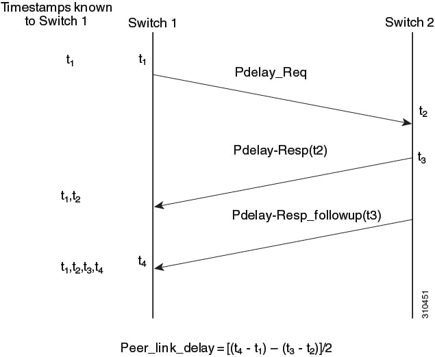
These messages are sent in the following sequence:
-
Port 1 generates timestamp t1 for a Pdelay_Req message.
-
Port 2 receives and generates timestamp t2 for this message.
-
Port 2 returns and generates timestamp t3 for a Pdelay_Resp message.
To minimize errors caused by frequency offset between the two ports, Port 2 returns the Pdelay_Resp message as quickly as possible after the receipt of the Pdelay_Req message.
-
Port 2 returns timestamps t2 and t3 in the Pdelay_Resp and Pdelay_Resp_Follow_Up messages respectively.
-
Port 1 generates timestamp t4 after receiving the Pdelay_Resp message. Port 1 then uses the four timestamps (t1, t2, t3, and t4) to calculate the mean link delay.
Synchronizing the Local Clock
In an ideal PTP network, the time source and the time recipient clocks operate at the same frequency. However, drift might occur on the network. Drift is the frequency difference between the time source and the time recipient clocks. You can compensate for drift by using the time stamp information in the device hardware and follow-up messages (intercepted by the switch) to adjust the frequency of the local clock to match the frequency of the time source clock.
Best Master Clock Algorithm
The Best Master Clock Algorithm (BMCA) is the basis of PTP functionality. The BMCA specifies how each clock on the network determines the best time source clock in its subdomain of all the clocks it can see, including itself. The BMCA runs on the network continuously and quickly adjusts for changes in network configuration.
The BMCA uses the following criteria to determine the best time source clock in the subdomain:
-
Clock quality, for example, GPS is considered the highest quality
-
Clock accuracy of the clock’s time base
-
Stability of the local oscillator
-
Closest clock to the grandmaster
In addition to identifying the best time source clock, the BMCA also ensures that clock conflicts do not occur on the PTP network by ensuring that:
-
Clocks do not have to negotiate with one another.
-
There is no misconfiguration, such as two time source clocks or no time source clocks, as a result of the time source clock identification process.
PTP Clocks
A PTP network is made up of PTP-enabled devices and devices that are not using PTP. The PTP-enabled devices typically consist of the following clock types.
Grandmaster Clock
Within a PTP domain, the grandmaster clock (GMC) is the primary source of time for clock synchronization using PTP. The GMC usually has a very precise time source, such as a GPS or atomic clock. When the network does not require any external time reference and only needs to be synchronized internally, the GMC can be free-running.
The switch can function as a hybrid grandmaster boundary clock using NTP as its source. For more information, see NTP to PTP Time Conversion.
Ordinary Clock
An ordinary clock is a PTP clock with a single PTP port. It functions as a node in a PTP network. Ordinary clocks are the most common clock type on a PTP network because they are used as end nodes on a network that is connected to devices requiring synchronization. Ordinary clocks have various interfaces to external devices.
Boundary Clock
A boundary clock in a PTP network operates in place of a standard network switch or router. Boundary clocks have more than one PTP port, and each port provides access to a separate PTP communication path. Boundary clocks provide an interface between PTP domains. They intercept and process all the PTP messages, and pass all other network traffic. The boundary clock uses the BMCA to select the best clock seen by any port. The selected port is then set to not be a time source. The time source port synchronizes the clocks connected downstream, while the port that is not a time source synchronizes with the upstream time source clock.
Transparent Clock
The role of transparent clocks in a PTP network is to update the time interval field that is a part of a PTP event message. This update compensates for switch delay and has an accuracy of within one picosecond.
There are two types of transparent clocks:
End-to-end (E2E) transparent clocks measure the PTP event message transit time (also known as resident time ) for SYNC and DELAY_REQUEST messages. This measured transit time is added to a data field (correction field) in the corresponding messages:
-
The measured transit time of a SYNC message is added to the correction field of the corresponding SYNC or the FOLLOW_UP message.
-
The measured transit time of a DELAY_REQUEST message is added to the correction field of the corresponding DELAY_RESPONSE message.
The time recipient uses this information when determining the offset between the time recipient's and the time source's time. E2E transparent clocks do not provide correction for the propagation delay of the link itself.
Peer-to-peer (P2P) transparent clocks measure PTP event message transit time in the same way E2E transparent clocks do, as described above. In addition, P2P transparent clocks measure the upstream link delay. The upstream link delay is the estimated packet propagation delay between the upstream neighbor P2P transparent clock and the P2P transparent clock under consideration.
These two times (message transit time and upstream link delay time) are both added to the correction field of the PTP event message. The correction field of the message received by the time recipient contains the sum of all link delays. In theory, this is the total end-to-end delay (from time source to time recipient) of a SYNC packet.
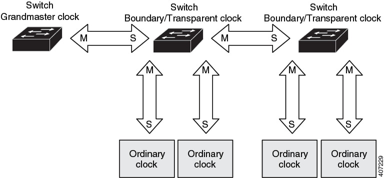
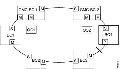
The following figure illustrates PTP clocks in a time source-time recipient hierarchy within a PTP network.
PTP Profiles
This section describes the following PTP profiles available on the switch:
-
Power Profile
-
Default Profile
The Power Profile is defined in PC37.238-2011 - IEEE Draft Standard Profile for Use of IEEE 1588 Precision Time Protocol in Power System Applications. The Cisco PTP implementation uses the terms Power Profile mode and Default Profile mode when referring to this IEEE 1588 profile and its associated configuration values.
The IEEE 1588 definition of a PTP profile is the set of allowed PTP features applicable to a device. A PTP profile is usually specific to a particular type of application or environment and defines the following values:
-
BMCA options
-
Configuration management options
-
Path delay mechanisms (peer delay or delay request-response)
-
Range and default values of all PTP configurable attributes and data set members
-
Transport mechanisms that are required, permitted, or prohibited
-
Node types that are required, permitted, or prohibited
-
Options that are required, permitted, or prohibited
Default Profile Mode
The default PTP profile mode in the switch is Default Profile mode. In this mode:
-
The PTP mode of transport is Layer 3.
-
The supported transparent clock mode is end-to-end (E2E).
The Default profile uses L3 transport multicast address 224.0.1.129 (MAC address 01-00-5e-00-01-81) for all PTP messages.
See Power Profile Mode for a list of the configuration values for the switch in Default Profile and Power Profile modes.
Power Profile Mode
The IEEE Power Profile defines specific or allowed values for the PTP networks used in power substations. The defined values include the optimum physical layer, the higher level protocol for PTP messages, and the preferred BMCA. The Power Profile values ensure consistent and reliable network time distribution within substations, between substations, and across wide geographic areas.
The switch is optimized for PTP in these ways:
-
Hardware: The switch uses FPGA and PHY for the PTP function. The PHY time stamps the Fast Ethernet and Gigabit Ethernet ports.
-
Software: In Power Profile mode, the switch uses the configuration values defined in the IEEE 1588 Power Profile standard.
The following table lists the configuration values defined by the IEEE 1588 Power Profile and the values that the switch uses for each PTP profile mode.
|
PTP Field |
Power Profile Value |
Switch Configuration Value |
|
|---|---|---|---|
|
Power Profile Mode |
Default Profile Mode |
||
|
Message transmission |
Ethernet 802.3 with Ethertype 0X88F7. PTP messages are sent as 802.1Q- tagged Ethernet frames with a default VLAN 0 and default priority 4. |
Access Ports : Untagged Layer 2 packets. Trunk Ports : 802.1Q tagged Layer 2 packets with native VLAN on the port and default priority value of 4. |
Layer 3 packets. By default, 802.1q tagging is disabled. |
|
MAC address : Nonpeer delay messages |
01-1B-19-00-00-00. |
01-1B-19-00-00-00. |
01-00-5e-00-01-81. |
|
MAC address : Peer delay messages |
01-80-C2-00-00-0E. |
01-80-C2-00-00-0E. |
Not applicable to this mode. |
|
Domain number |
0. |
0. |
0. |
|
Path delay calculation |
Peer-to-peer transparent clocks. |
Peer-to-peer transparent clocks using the peer_delay mechanism. |
End-to-end transparent clocks using the delay_request mechanism. |
|
BMCA |
Enabled. |
Enabled. |
Enabled. |
|
Clock type |
Two-step clocks are supported. |
Two-step. |
Two-step. |
|
Time scale |
Epoch.1 |
Epoch. |
Epoch. |
|
Grandmaster ID and local time determination |
PTP-specific TLV (type, length, value) to indicate Grandmaster ID. |
PTP-specific TLV to indicate Grandmaster ID. |
PTP-specific type, length, and value to indicate Grandmaster ID. |
|
Time accuracy over network hops |
Over 16 hops, the time recipient device synchronization accuracy is within 1 usec (1 microsecond). |
Over 16 hops, the time recipient device synchronization accuracy is within 1 usec (1 microsecond). |
Not applicable in this mode. |
Tagging Behavior for PTP Packets
The following table describes the switch tagging behavior in Power Profile and Default Profile modes.
|
Switch Port Mode |
Configuration |
Power Profile Mode |
Default Profile Mode |
||
|---|---|---|---|---|---|
|
Behavior |
Priority |
Behavior |
Priority |
||
|
Trunk Port |
vlan dot1q tag native enabled |
Switch tags packets |
7 |
Switch tags packets |
7 |
|
Trunk Port |
vlan dot1q tag native disabled |
PTP software tags packets |
4 |
Untagged |
None |
|
Access Port |
N/A |
Untagged |
None |
Untagged |
None |
PTP Clock Modes Supported on the Switch
PTP synchronization behavior depends on the PTP clock mode that you configure on the switch. You can configure the switch for one of the global modes described below.
See Guidelines and limitations for guidelines to configure each of the clock modes.
Grandmaster-Boundary Clock Mode
The switch can function as a hybrid grandmaster boundary clock using NTP as its source. For more information, see NTP to PTP Time Conversion.
Boundary Clock Mode
A switch configured for boundary clock mode participates in selecting the best time source clock on the subdomain, selecting from all the clocks it can see, including itself. If the switch does not detect a more accurate clock than itself, then the switch becomes the time source clock. If a more accurate clock is detected, then the switch synchronizes to that clock and becomes a time recipient clock.
After initial synchronization, the switch and the connected devices exchange PTP timing messages to correct the changes caused by clock offsets and network delays.
Forward Mode
A switch configured for forward mode passes incoming PTP packets as normal multicast traffic.
E2E Transparent Clock Mode
A switch configured for end-to-end transparent clock mode does not synchronize its clock with the time source clock. A switch in this mode does not participate in time source clock selection and uses the default PTP clock mode on all ports.
P2P Transparent Clock Mode
A switch configured for peer-to-peer transparent clock mode does not synchronize its clock with the time source clock. A switch in this mode does not participate in time source clock selection and uses the default PTP clock mode on all ports.
Configurable Boundary Clock Synchronization Algorithm
You can configure the BC synchronization algorithm to accommodate various PTP use cases, depending on whether you need to prioritize filtering of input time errors or faster convergence. A PTP algorithm that filters packet delay variation (PDV) converges more slowly than a PTP algorithm that does not.
By default, the BC uses a linear feedback controller (that is, a servo) to set the BC's time output to the next clock. The linear servo provides a small amount of PDV filtering and converges in an average amount of time. For improved convergence time, BCs can use the TC feedforward algorithm to measure the delay added by the network elements forwarding plane (the disturbance) and use that measured delay to control the time output.
While the feedforward BC dramatically speeds up the boundary clock, the feedforward BC does not filter any PDV. The adaptive PDV filter provides high quality time synchronization in the presence of PDV over wireless access points (APs) and enterprise switches that do not support PTP and that add significant PDV.
Three options are available for BC synchronization (all are compliant with IEEE 1588-2008):
-
Feedforward—For very fast and accurate convergence; no PDV filtering.
-
Adaptive—Filters as much PDV as possible, given a set of assumptions about the PDV characteristics, the hardware configuration, and the environmental conditions.
Note
With the adaptive filter, the switch does not meet the time performance requirements specified in ITU-T G.8261.
-
Linear—Provides simple linear filtering (the default).
Adaptive mode (ptp transfer filter adaptive ) is not available in Power Profile mode.
For configuration information, see Configuring PTP on the Switch.
 Feedback