Configuring Static IP Routing
Available Languages
Table of Contents
Configuring IP Unicast Routing
Assigning IP Addresses to SVIs
Configuring Static Unicast Routes
Monitoring and Maintaining the IP Network
Configuring IP Unicast Routing
This chapter describes how to configure IP Version 4 (IPv4) static IP unicast routing on the Catalyst switch. Static routing is supported only on switched virtual interfaces (SVIs) and not on physical interfaces. The switch does not support routing protocols.
Unless otherwise noted, the term switch refers to a standalone switch and a switch stack. A switch stack operates and appears as a single router to the rest of the routers in the network.
For complete syntax and usage information for the commands used in this chapter, see the Cisco IOS IP Command Reference, Volume 1 of 3: Addressing and Services, Release 12.2
This chapter consists of these sections:
- Understanding IP Routing
- Steps for Configuring Routing
- Enabling IP Unicast Routing
- Configuring Static Unicast Routes
- Monitoring and Maintaining the IP Network

Note![]() When configuring routing parameters on the switch and to allocate system resources to maximize the number of unicast routes allowed, use the sdm prefer lanbase-routing global configuration command to set the Switch Database Management (sdm) feature to the routing template. For more information on the SDM templates, see Chapter 8, “Configuring SDM Templates” or see the sdm prefer command in the command reference for this release.
When configuring routing parameters on the switch and to allocate system resources to maximize the number of unicast routes allowed, use the sdm prefer lanbase-routing global configuration command to set the Switch Database Management (sdm) feature to the routing template. For more information on the SDM templates, see Chapter 8, “Configuring SDM Templates” or see the sdm prefer command in the command reference for this release.
Understanding IP Routing
In some network environments, VLANs are associated with individual networks or subnetworks. In an IP network, each subnetwork is mapped to an individual VLAN. Configuring VLANs helps control the size of the broadcast domain and keeps local traffic local. However, network devices in different VLANs cannot communicate with one another without a Layer 3 device to route traffic between the VLAN, referred to as inter-VLAN routing. You configure one or more routers to route traffic to the appropriate destination VLAN.
Figure 1-1 shows a basic routing topology. Switch A is in VLAN 10, and Switch B is in VLAN 20. The router has an interface in each VLAN.
Figure 1-1 Routing Topology Example
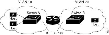
When Host A in VLAN 10 needs to communicate with Host B in VLAN 10, it sends a packet addressed to that host. Switch A forwards the packet directly to Host B, without sending it to the router.
When Host A sends a packet to Host C in VLAN 20, Switch A forwards the packet to the router, which receives the traffic on the VLAN 10 interface. The router checks the routing table, finds the correct outgoing interface, and forwards the packet on the VLAN 20 interface to Switch B. Switch B receives the packet and forwards it to Host C.
Types of Routing
Routers and Layer 3 switches can route packets in three different ways:
- By using default routing to send traffic with a destination unknown to the router to a default outlet or destination.
- By using static routes to forward packets from predetermined ports through a single path into and out of a network.
- By dynamically calculating routes by using a routing protocol.
The switch supports static routes; it does not support routing protocols.
IP Routing and Switch Stacks
A switch stack appears to the network as a single switch, regardless of which switch in the stack is connected to a peer. For additional information about switch stack operation, see Chapter 5, “Managing Switch Stacks.”
The stack master performs these functions:
- The MAC address of the stack master is used as the router MAC address for the whole stack, and all outside devices use this address to send IP packets to the stack.
- All IP packets that require software forwarding or processing go through the CPU of the stack master.
Stack members perform these functions:
- They act as routing standby switches, ready to take over in case they are elected as the new stack master if the stack master fails.
- They program the routes into hardware.
If a stack master fails, the stack detects that the stack master is down and elects one of the stack members to be the new stack master. During this period, except for a momentary interruption, the hardware continues to forward packets.
At election, the new stack master performs these functions:
- It starts generating, receiving, and processing routing updates.
- It builds routing tables and distributes it to stack members.
- It uses its MAC address as the router MAC address. To notify its network peers of the new MAC address, it periodically (every few seconds for 5 minutes) sends a gratuitous ARP reply with the new router MAC address.
Note![]() If you configure the persistent MAC address feature on the stack and the stack master changes, the stack MAC address does not change for the configured time period. If the previous stack master rejoins the stack as a member switch during that time period, the stack MAC address remains the MAC address of the previous stack master. See the “Enabling Persistent MAC Address” section on page 5-18.
If you configure the persistent MAC address feature on the stack and the stack master changes, the stack MAC address does not change for the configured time period. If the previous stack master rejoins the stack as a member switch during that time period, the stack MAC address remains the MAC address of the previous stack master. See the “Enabling Persistent MAC Address” section on page 5-18.
Steps for Configuring Routing
By default, IP routing is disabled on the switch, and you must enable it before routing can take place. For detailed IP routing configuration information, see the Cisco IOS IP Configuration Guide, Release 12.2 from the Cisco.com page under Documentation > Cisco IOS Software > 12.2 Mainline > Configuration Guides.
In the following procedures, the specified interface must be a switch virtual interface (SVI)—a VLAN interface created by using the interface vlan vlan_id global configuration command and by default a Layer 3 interface. All Layer 3 interfaces on which routing will occur must have IP addresses assigned to them. See the “Assigning IP Addresses to SVIs” section on page 38-4.
Note![]() The switch supports 16 user-configured static routes in addition to any directly connected routes and default routes for the management interface. switch can have an IP address assigned to each SVI. The number of routed ports and SVIs that you can configure is not limited by software. However, the interrelationship between this number and the number and volume of features being implemented might have an impact on CPU utilization because of hardware limitations. Before enabling routing, enter the sdm prefer lanbase-routing global configuration command and reload the switch.
The switch supports 16 user-configured static routes in addition to any directly connected routes and default routes for the management interface. switch can have an IP address assigned to each SVI. The number of routed ports and SVIs that you can configure is not limited by software. However, the interrelationship between this number and the number and volume of features being implemented might have an impact on CPU utilization because of hardware limitations. Before enabling routing, enter the sdm prefer lanbase-routing global configuration command and reload the switch.
Configuring routing consists of several procedures:
- To support VLAN interfaces, create and configure VLANs on the switch, and assign VLAN membership to Layer 2 interfaces. For more information, see Chapter 14, “Configuring VLANs.”
- Configure Layer 3 interfaces (SVIs).
- Enable IP routing on the switch.
- Assign IP addresses to the Layer 3 interfaces.
- Configure static routes
Enabling IP Unicast Routing
By default, the switch is in Layer 2 switching mode and IP routing is disabled. To use the Layer 3 capabilities of the switch, you must enable IP routing.
Beginning in privileged EXEC mode, follow these steps to enable IP routing:
Use the no ip routing global configuration command to disable routing.
Assigning IP Addresses to SVIs
A required task for configuring IP routing is to assign IP addresses to Layer 3 network interfaces to enable the interfaces and allow communication with the hosts on those interfaces that use IP. IP routing is disabled by default and no IP addresses are assigned to SVIs.
An IP address identifies a location to which IP packets can be sent. Some IP addresses are reserved for special uses and cannot be used for host, subnet, or network addresses. RFC 1166, “Internet Numbers,” contains the official description of IP addresses.
An interface can have one primary IP address. A mask identifies the bits that denote the network number in an IP address. When you use the mask to subnet a network, the mask is referred to as a subnet mask. To receive an assigned network number, contact your Internet service provider.
Beginning in privileged EXEC mode, follow these steps to assign an IP address and a network mask to an SVI
Configuring Static Unicast Routes
Static unicast routes are user-defined routes that cause packets moving between a source and a destination to take a specified path. Static routes can be important if the router cannot build a route to a particular destination and are useful for specifying a gateway of last resort to which all unroutable packets are sent.
Beginning in privileged EXEC mode, follow these steps to configure a static route:
Use the no ip route prefix mask { address | interface } global configuration command to remove a static route. The switch retains static routes until you remove them.
When an interface goes down, all static routes through that interface are removed from the IP routing table. When the software can no longer find a valid next hop for the address specified as the forwarding router's address in a static route, the static route is also removed from the IP routing table.
Monitoring and Maintaining the IP Network
You can specific statistics for the routing table or database. Use the privileged EXEC commands in Table 1-1 to clear display status:
show platform ip unicast
Use the show platform ip unicast privileged EXEC command to display platform-dependent IP unicast routing information.
show platform ip unicast { adjacency | cef-idb | counts | dhcp | failed { adjacency | arp [ A.B.C.D ] | route } | loadbalance | mpaths | proxy | route | standby | statistics | table | trace } [ | { begin | exclude | include } expression ]
Note![]() This command is available only if your switch is running the IP services image.
This command is available only if your switch is running the IP services image.
Syntax Description
Note![]() Though visible in the command-line help strings, the proxy and table keywords are not supported.
Though visible in the command-line help strings, the proxy and table keywords are not supported.
Command Modes
Usage Guidelines
You should use this command only when you are working directly with a technical support representative while troubleshooting a problem. Do not use this command unless a technical support representative asks you to do so.
Expressions are case sensitive. For example, if you enter | exclude outpu t, the lines that contain output do not appear, but the lines that contain Output appear.
Note: other enabled commands are IOS PI and we do not include in our docs.
 Feedback
Contact Cisco
- Open a Support Case

- (Requires a Cisco Service Contract)
This Document Applies to These Products
- Collaboration Endpoints - Retired Products
- Conferencing - Retired Products
- Contact Center - Retired Products
- Optical Networking - Retired Products
- Routers - Retired Products
- Security - Retired Products
- Servers - Unified Computing (UCS) Retired Products
- Storage Networking Retired Products
- Switches - Retired Products
- Video - Retired Products
- Wireless - Retired Products