
Cisco C9610 Series Supervisor Engine Installation Note
Cisco C9610 series supervisor engine modules
The Cisco C9610 supervisor engines are high-performance supervisor engines, optimized for large-scale enterprise and campus core network deployments. The supervisor engines acts as the centralized management and control module, and delivers switching, routing, and programmability capabilities. The Cisco C9610R chassis supports two supervisor engines.
This table provides the list of supported supervisor engines.
|
Product ID |
Description |
|---|---|
|
C9610-SUP-3 |
Cisco C9610 Series Supervisor 3 module |
|
C9610-SUP-3XL |
Cisco C9610 Series Supervisor 3XL module |
Chassis compatibility
This section lists the supervisor engines and the compatibility with the Cisco C9610R chassis.
|
Compatibility information |
C9610-SUP-3 |
C9610-SUP-3XL |
|---|---|---|
|
Chassis compatibility |
Supported on Cisco C9610R series 10 slot chassis (C9610R) with two supervisor engine modules, and eight line card slots. |
|
|
Minimum software requirements |
Cisco IOS XE 17.18.1 and later releases |
Cisco IOS XE 17.18.1 and later releases |
|
Chassis slot restrictions |
C9610R: Slots 5 and 6 only (redundant supervisor engines supported). The primary supervisor engine can be installed in either slot. |
|
|
Bandwidth per slot |
6.4 Tbps full-duplex per slot |
6.4 Tbps full-duplex per slot |
|
Memory |
Double Data Rate 4 Synchronous Dynamic Random-Access Memory: 32 GB |
Double Data Rate 4 Synchronous Dynamic Random-Access Memory: 32 GB |
|
Onboard flash: 32 GB |
Onboard flash: 32 GB |
|
|
Line card compatibility |
|
|
|
Supported with the LC adapter, C9610-LC-ADPT
|
Supported with the LC adapter, C9610-LC-ADPT
|
|
C9610-SUP-3
The supervisor engine, C9610-SUP-3 supported on the Cisco C9610R chassis is based on the Cisco Silicon One E100 ASIC.
This illustration shows the front view of C9610-SUP-3 with the major features identified.

|
1 |
Ejector levers |
7 |
RJ-45 console port |
|
2 |
Supervisor engine LEDs |
8 |
10 G SFP+ management port |
|
3 |
10MHz (I/O) DIN port |
9 |
USB Type A host port |
|
4 |
1PPS (I/O) DIN port |
10 |
USB C console port |
|
5 |
TOD PTP RJ-45 port |
11 |
Optional RFID |
|
6 |
RJ-45 Ethernet management port |
12 |
SATA SSD |
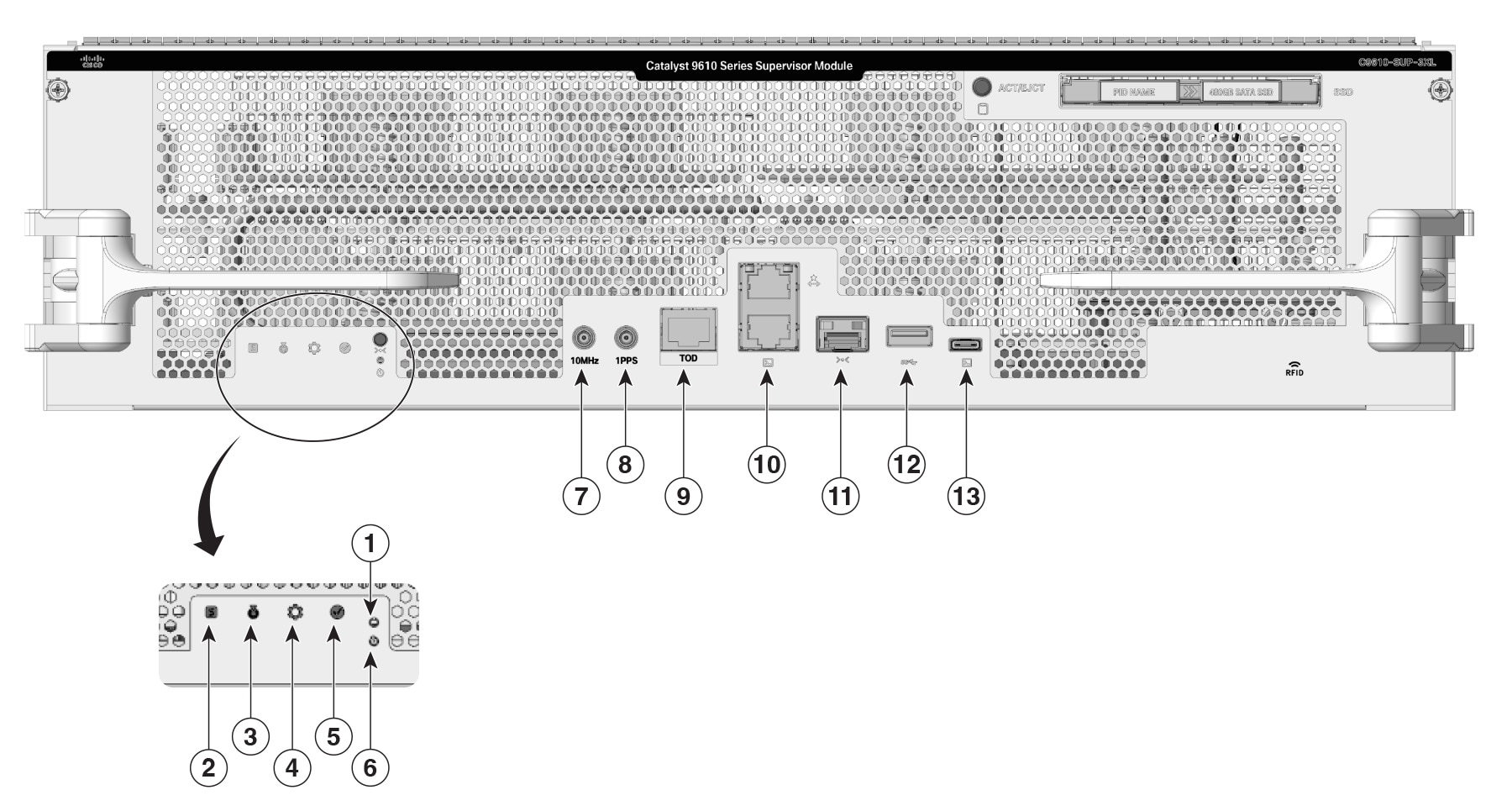
C9610-SUP-3XL
The supervisor engine, C9610-SUP-3XL supported on the Cisco C9610R chassis is based on the Cisco Silicon One Kypton (K100) ASIC.
This illustration shows the front view of C9610-SUP-3XL with the major features identified.
|
1 |
Ejector levers |
7 |
RJ-45 console port |
|
2 |
Supervisor engine LEDs |
8 |
10 G SFP+ management port |
|
3 |
10MHz (I/O) DIN port |
9 |
USB Type A host port |
|
4 |
1PPS (I/O) DIN port |
10 |
USB C console port |
|
5 |
TOD PTP RJ-45 port |
11 |
Optional RFID |
|
6 |
RJ-45 Ethernet management port |
12 |
SATA SSD |
Ports and LEDs
This table describes the ports and LEDs available on the supervisor engine modules of Cisco C9610 Series Smart Switches.
|
Feature |
Description |
|---|---|
|
USB Type C console port |
The USB Type C port provides console connection using a USB C cable. |
|
USB 3.0 Type A host port |
The supervisor engine provides a single USB 3.0 Type A port for external storage and dongles. It supports USB versions 3.0, 2.0, 1.1, and 1.0. |
|
10/100/1000 Ethernet Management port (RJ-45 connector) |
The Ethernet management port is a Layer 3 host port to which you can connect a PC. By default, the Ethernet management port is enabled. You can use the Ethernet management port for network management. |
|
Console port (RJ-45 connector) |
The RJ-45 console port is a serial communication port used for device management and configuration. It allows direct access to the Cisco device’s CLI for initial setup, troubleshooting, or recovery when network access is unavailable. The console port transmits serial data rather than Ethernet traffic. The RJ-45 console port uses the optional RJ-45-to-DB8 female cable physical connector. |
|
Blue beacon |
The blue beacon LED on the front panel of the supervisor engine that allows easy identification of the device. By default, the blue beacon LED is off. You need to switch it on through the CLI. |
|
Status LED |
The status LED indicates the status of the supervisor engine.
|
|
System LED |
Indicates the environmental monitors of the system. |
|
Active LED |
Indicates whether the supervisor is in active, standby, or ROMMON mode. |
|
Reset button |
The reset switch is used to reset and restart a supervisor engine. |
|
10G SFP+ management port |
The supervisor engine has one 10G SFP+ management port. This port requires small form-factor pluggable (SFP+) transceivers. |
|
10MHz |
A 10MHz (I/O) SyncE DIN port is available on the supervisor engine. This is an interface port used for precise frequency synchronization in networking equipments.  Note NoteThis port is not enabled. |
|
1PPS |
The1PPS (I/O) SyncE DIN port is an interface that inputs or outputs a One Pulse Per Second (1PPS) timing signal for precise time synchronization, using a DIN-style 1.0/2.3 coaxial connector typically with 50-ohm impedance. NoteThis port is not enabled. |
|
TOD |
The Time of Day (TOD) port is used to receive or provide precise time information from external timing sources. NoteThis port is not enabled. |
|
SATA SSD module slot |
The supervisor module has a Serial Advanced Technology Attachment (SATA) connector that supports solid state drive (SSD) local storage for container-based application hosting. This is an optional feature. |
|
Model number |
Supervisor engine model number. |
|
LEDs |
Various LEDs available on the supervisor engine. |
Front panel components
This section describes the front panel components of the Cisco C9610 supervisor engine modules.
Console ports
The front panel of the supervisor module provides two types of console ports.
- RJ-45 console port: This port provides universal asynchronous receiver/transmitter (UART) support to access the route processor with a serial console running at 9600 baud rate with 8 bits for data, no parity bit, and 1 stop bit.
- USB C console port: This port provides direct access to the CLI of the switch. It connects a computer or terminal directly to the Cisco device for configuration purposes. This port also enables terminal communication to configure routers, switches, firewalls, or other Cisco network devices.
Only one of the consoles is active at a time. When a USB host (PC) is plugged into the USB console port, the hardware automatically switches over to use the USB console. Only a PC that has the necessary USB console device driver causes the USB console to become active. Plugging in a PC that does not have the USB console driver support does not cause a switchover. When the USB cable is removed, or the PC deactivates the USB connection, or a host is not detected on the USB console, the hardware automatically switches to the RJ-45 console interface.
The console port allows you to perform the following functions:
- Configure the switch from the CLI
- Monitor network statistics and errors
- Configure SNMP agent parameters
Management ports
The supervisor module provides two types of management ports, 10/100/1000BASE-T RJ-45 port and 10G SFP+ port. The RJ-45 and SFP+ management ports provide out-of-band (OOB) Ethernet network connectivity, which enables you to use the CLI to manage the switch using its IP address. The management ports support TFTP image downloading, network management, SNMP, Telnet, and SSH connections.
- SFP+ management port: This port is a fiber port that is referred to as TenGigabitEthernet 0/1 . C9610-SUP-3 and C9610-SUP-3XL modules has one SFP+ port that supports 10G speeds.
- Ethernet management port: This port is a copper Ethernet port that is referred to as GigabitEthernet0/0 (Gi0/0) port. The Ethernet management port supports speed up to 10/100/1000 Mbps and is set to auto-negotiate.
Based on the cable and connectors that you are using, you can use one of these ports to connect the management interface to the network. Use only one of these management ports; the switch does not support the use of both management ports. By default, the Ethernet management port is enabled.
Use the management port instead of the console port for network management. The switch cannot route packets from a management port to a network port, and from a network port to a management port. To obtain this, the management interface is automatically placed in a separate routing domain or virtual routing and forwarding (VRF) domain, called Mgmt-vrf. The devices support OOB management through the Mgmt-vrf, which is used to segment management traffic from the global routing table of the switch.
When managing a switch, connect the PC to the management port of the supervisor engine.
Reset button
A recessed access button is available on the front panel of the supervisor module to reset and restart the module. Using a pin, press and hold the button inwards for 5 seconds to reset and restart the module.
Optional RFID tag
The Cisco C9610 supervisor engine modules have an optional, built-in, front-facing, passive Radio Frequency Ientification (RFID) tag that uses Ultra High Frequency (UHF) RFID technology and requires an RFID reader with compatible software. It provides auto-identification capabilities for asset management and tracking. The RFID tags are compatible with the Generation 2 GS1 EPC Global Standard and are ISO 18000-6C compliant. They operate in the 860- to 960-MHz UHF band. For more information, see Radio Frequency Identification (RFID) on Cisco Catalyst 9000 Family Switches White Paper.
For Cisco C9610 series smart switches, the RFID tag is optional. Based on your requirements, you can choose to order the switch with or without an RFID tag at the time of purchase.
Supervisor engine LEDs
This illustration shows the LEDs available on C9610 supervisor engines.
|
1 |
Status LED |
5 |
Mode button NoteNot supported |
|
2 |
Blue beacon LED |
6 |
Reset button |
|
3 |
System LED |
7 |
SSD Eject/Status LED |
|
4 |
Active LED |
- |
- |
LEDs and status
This section describes the LEDs and their status. All these LEDs are on the front panel of the supervisor engine.
|
LED type |
LED position or color |
Status |
|---|---|---|
 Status LED |
Green |
Indicates that all the diagnostic tests have passed after image booting. |
|
Amber |
Indicates a major environmental warning. |
|
|
Red |
Indicates a fault in the module due to a parity error, failed diagnostic tests, or hardware failure. |
|
|
Off |
Indicates that the supervisor module is disabled or is not powered up. |
|
 Blue beacon LED |
Solid blue |
Identifies the supervisor module receiving the beacon signal. By default the blue beacon LED is off. You needs to switch it on using the CLI. |
 System LED |
Green |
Indicates that the environmental monitors are normal. |
|
Amber |
Indicates a minor fault such as a partial power supply or fan failure. |
|
|
Red |
Indicates a major fault, for example, situations where the temperature of the supervisor module exceeds the critical threshold. |
|
 |
Green |
Indicates that the supervisor module is operational, and is functioning as the active supervisor in redundant supervisor module configurations. |
|
Amber |
Indicates one of the following:
|
|
|
Mode button |
Not supported |
|
|
Reset button |
Reset button |
|
|
SSD LED |
Green |
SSD is operational. |
|
Yellow |
Indicates that the SSD is being unmounted. |
|
|
Amber |
SSD is unmounted. |
|
|
Off |
SSD is not available in the supervisor engine. |
|
SATA SSD modules
The Cisco C9610 supervisor engine modules support pluggable Serial Advanced Technology Attachment (SATA) Solid State Drive (SSD) module. The SATA SSD module slot is located on the front panel of the supervisor engine.
The SATA module is a field replaceable unit (FRU). A hot-swap button on the front panel of the supervisor engine initiates the removal of the SATA module. You must press the button to safely eject the SSD from the supervisor engine.
The SSD module storage capacity ranges are 240GB, 480GB and 960GB.
USB Type A port
The USB 3.0 Type A port provides access to external USB flash devices (also known as thumb drives or USB keys). The port supports Cisco USB flash drives with capacities from 64MB to 16GB. USB devices with port densities of 64 MB, 128 MB, 256 MB, 1 GB, 4 GB, 8 GB, and 16 GB are supported. The port provides 2.5 W of power to the device connected to the port.
Cisco IOS XE software provides standard file system access to the flash device, such as read, write, erase, and copy, as well as the ability to format the flash device with a FAT file system.
These guidelines apply when using USB flash drives.
- There must at least be one partition on the USB flash drive. If the drive has more than one partition, only the first partition is visible in the system (Cisco IOS XE).
- If you partition the flash drive, we recommend that you use a Linux system to perform this task. This ensures that the first partition is a usable partition when connected to the switch. Using a Windows or MacBook machine utility to perform this task may result in two partitions on the drive by default (partition for system information + actual usable partition). When such a flash drive is connected to the switch, the system displays only the first system information partition, and not the actual usable partition.
USB Type C port
The USB Type C port provides console connection using a USB C cable. It functions as a host to manage connected peripherals.
10MHz (I/O) DIN port
A 10MHz (I/O) DIN connector is an interface port used for precise frequency synchronization in networking equipments. This port can be configured as input ports from an external clocking and timing source, like GPS.
NoteThis interface port is not enabled.
1PPS (I/O) DIN port
The1PPS (I/O) DIN connector is an interface that inputs or outputs a One Pulse Per Second (1PPS) timing signal for precise time synchronization, using a DIN-style 1.0/2.3 coaxial connector typically with 50-ohm impedance.
NoteThis interface port is not enabled.
TOD PTP RJ-45 port
A TOD PTP RJ-45 port is a physical Ethernet port that supports Precision Time Protocol (PTP) timing synchronization and Time of Day (TOD) functions using an RJ-45 connector.
TOD refers to a time source or time-stamping capability available at the hardware or system level for precise timekeeping. It may be used in conjunction with PTP to obtain and distribute exact time-of-day information across devices.
NoteThis interface port is not enabled.
Preparing for the installation and removal of supervisor engine modules
Before you install or remove a supervisor engine on a Cisco C9610R chassis
- adhere to the safety requirements,
- refer how to prevent ESD damage, and
- ensure that you have the right tools.
Safety warnings
Safety warnings appear throughout this publication in procedures that may harm you if you perform them incorrectly. A warning symbol precedes each warning statement. The warnings below are general warnings that are applicable to the entire publication.
DANGERThe supervisor engine modules are very heavy and must be handled carefully. In case the modules are dropped to the ground and it can hurt the user.
 Warning
Statement 1071—Warning Definition
IMPORTANT SAFETY INSTRUCTIONS
Before you work on any equipment, be aware of the hazards involved with electrical circuitry and be familiar with standard practices for preventing accidents. Read the installation instructions before using, installing, or connecting the system to the power source. Use the statement number at the beginning of each warning statement to locate its translation in the translated safety warnings for this device.
SAVE THESE INSTRUCTIONS
 Warning
Statement 445—Connect the Chassis to Earth Ground
To reduce the risk of electric shock, connect the chassis of this equipment to permanent earth ground during normal use.
WarningStatement 1008—Class 1 Laser Product
This product is a Class 1 laser product.
WarningStatement 1015—Battery Handling
To reduce risk of fire, explosion, or leakage of flammable liquid or gas:
- Replace the battery only with the same or equivalent type recommended by the manufacturer.
- Do not dismantle, crush, puncture, use a sharp tool to remove, short the external contacts, or dispose of the battery in fire.
- Do not use if battery is warped or swollen.
- Do not store or use battery in a temperature above 104°F (40ºC).
- Do not store or use battery in low air pressure environment 10.1 psia at 10,000 feet (3,000 meters).
WarningStatement 1029—Blank Faceplates and Cover Panels
Blank faceplates and cover panels serve three important functions: they reduce the risk of electric shock and fire, they contain electromagnetic interference (EMI) that might disrupt other equipment, and they direct the flow of cooling air through the chassis. Do not operate the system unless all cards, faceplates, front covers, and rear covers are in place.
WarningStatement 1055—Class 1/1M Laser
Invisible laser radiation is present. Do not expose to users of telescopic optics. This applies to Class 1/1M laser products.
 Warning
Statement 1073—No User-Serviceable Parts
There are no serviceable parts inside. To avoid risk of electric shock, do not open.
WarningStatement 1056—Unterminated Fiber Cable
Invisible laser radiation may be emitted from the end of the unterminated fiber cable or connector. Do not view directly with optical instruments. Viewing the laser output with certain optical instruments, for example, eye loupes, magnifiers, and microscopes, within a distance of 100 mm, may pose an eye hazard.
WarningStatement 1074—Comply with Local and National Electrical Codes
To reduce risk of electric shock or fire, installation of the equipment must comply with local and national electrical codes.
NoteStatement 1089—Instructed and Skilled Person Definitions
An instructed person is someone who has been instructed and trained by a skilled person and takes the necessary precautions when working with equipment.
A skilled person or qualified personnel is someone who has training or experience in the equipment technology and understands potential hazards when working with equipment.
WarningStatement 1090—Installation by Skilled Person
Only a skilled person should be allowed to install, replace, or service this equipment. See statement 1089 for the definition of a skilled person.
WarningStatement 1091—Installation by an Instructed Person
Only an instructed person or skilled person should be allowed to install, replace, or service this equipment. See statement 1089 for the definition of an instructed or skilled person.
WarningStatement 1099—Before Connecting to System Power Supply
High touch/leakage current—Permanently connected protective earth ground is essential before connecting to the system power supply.
NoteStatement 7001—ESD Mitigation
This equipment may be ESD sensitive. Always use an ESD ankle or wrist strap before handling equipment. Connect the equipment end of the ESD strap to an unfinished surface of the equipment chassis or to the ESD jack on the equipment if provided.
WarningStatement 7003—Shielded Cable Requirements for Intrabuilding Lightning Surge
The intrabuilding port(s) of the equipment or subassembly must use shielded intrabuilding cabling/wiring that is grounded at both ends.
The following port(s) are considered intrabuilding ports on this equipment: RJ45 Copper Ethernet Port
NoteStatement 7004—Special Accessories Required to Comply with GR-1089 Emission and Immunity Requirements
To comply with the emission and immunity requirements of GR-1089, shielded cables are required for the following ports: RJ45 Copper Ethernet Port
WarningStatement 7005—Intrabuilding Lightning Surge and AC Power Fault
The intrabuilding port(s) of the equipment or subassembly is suitable for connection to intrabuilding or unexposed wiring or cabling only. The intrabuilding port(s) of the equipment or subassembly MUST NOT be metallically connected to interfaces that connect to the OSP or its wiring for more than 6 meters (approximately 20 feet). These interfaces are designed for use as intrabuilding interfaces only (Type 2, 4, or 4a ports as described in GR-1089) and require isolation from the exposed OSP cabling. The addition of primary protectors is not sufficient protection in order to connect these interfaces metallically to an OSP wiring system.
The following ports are considered intrabuilding ports on the equipment: RJ45 Copper Ethernet Port
WarningStatement 9001—Product Disposal
Ultimate disposal of this product should be handled according to all national laws and regulations.
Preventing ESD damage
An electrostatic discharge (ESD) strap, is a tool used to prevent damage to sensitive electronic components from static electricity. It is a wrist strap that connects the wearer to a grounding point, ensuring that any static charge on the body is safely dissipated to the ground, thus preventing damage to electronic components during handling.
ESD damage might occur when modules or other field replaceable units (FRUs) are improperly handled, resulting in intermittent or complete failure of the modules or FRUs. Modules consist of printed circuit boards that are fixed in metal carriers. EMI shielding and connectors are integral components of a carrier. Although the metal carrier helps to protect the board from ESD, always use an ESD-grounding strap when handling modules. To prevent ESD damage, follow these guidelines.
- Always use an ESD wrist or ankle strap and ensure that it makes good skin contact.
- Connect the equipment end of the strap to an unfinished chassis surface.
- When installing a component, use an available ejector lever to properly seat the bus connectors in the backplane or midplane. These devices prevent accidental removal, provide proper grounding for the system, and help to ensure that bus connectors are properly seated.
- When removing a component, use an available ejector lever to release the bus connectors from the backplane or midplane.
- Handle carriers by available handles or edges only; avoid touching the printed circuit boards or connectors.
- Place a removed component board-side-up on an antistatic surface or in a static-shielding container. If you plan to return the component to the factory, immediately place it in a static-shielding container.
- Avoid contact between the printed circuit boards and clothing. The wrist strap only protects components from ESD voltages on the body; ESD voltages on clothing can still cause damage.
- Never attempt to remove the printed circuit board from the metal carrier.
Tools required
You need these tools to install or remove supervisor engines and line cards:
- Your own ESD-prevention equipment or the disposable grounding wrist strap included with all upgrade kits, FRUs, and spares.
- Antistatic mat or antistatic bag
Removing a supervisor engine module
WarningStatement 1051—Laser Radiation
Invisible laser radiation may be emitted from disconnected fibers or connectors. Do not stare into beams or view directly with optical instruments.
 Caution
To prevent ESD damage, handle the supervisor engine by the carrier edges only.
Follow this procedure to remove a supervisor engine from the C9610R chassis. This procedure is the same for both the supported supervisor engine modules.
Before you begin
DANGERThe supervisor engine modules are very heavy and must be handled carefully; if dropped, it can hurt the user.
- You will need a slot blank cover (C9610-SUP-BLANK=) if the slot is to remain empty.
- Install dust plugs into the transceiver’s optical bores if the module is equipped with removable optical transceivers. This prevents possible dust contamination, which can affect port performance.
- Take necessary precautions to prevent ESD damage. Wear a grounded ESD wrist strap while handling the modules.
Step 1 | Hold the ejector lever on both sides and push the levers in, towards the faceplate to push the supervisor engine a bit inward. While pressing the ejector levers, press the buttons on the left and right ejector handles to unlock the levers. 
To view the animation in PDF, click this link. |
Step 2 | Pivot both the ejector levers outward simultaneously to remove the Supervisor engine. 
To view the animation in PDF, click this link. |
Step 3 | Disengage the supervisor engine from the backplane connector and pull out the supervisor engine using the ejector lever handles. Carefully slide the supervisor engine out of the slot. Halfway through pulling out the supervisor engine the left and right slot guides will be visible. Hold these slot guides on both sides and carefully slide the supervisor engine out of the slot. 
To view the animation in PDF, click this link. 
To view the animation in PDF, click this link. |
Step 4 | Place the supervisor engine on an antistatic mat or in an antistatic bag. |
Step 5 | Install a replacement supervisor engine after a 15-second wait. Alternatively, if the supervisor slot should remain empty, install a blank slot cover (C9610-SUP-BLANK=). Blanks should only be removed when installing a module and must be replaced if a module is ever removed. A syslog message is generated every 5 minutes when an empty slot is detected. You must insert a module or a slot blank to avoid chassis overheating. WarningStatement 1029—Blank Faceplates and Cover Panels Blank faceplates and cover panels serve three important functions: they reduce the risk of electric shock and fire, they contain electromagnetic interference (EMI) that might disrupt other equipment, and they direct the flow of cooling air through the chassis. Do not operate the system unless all cards, faceplates, front covers, and rear covers are in place. |
Installing a supervisor engine module
CautionYou can install supervisor engine modules in slot 5 and/or slot 6 of the Cisco C9610R chassis. We recommend that you install the supervisor engine modules slowly.
- When transporting or handling the supervisor engines, take care to avoid damage to the connectors on the rear panel, particularly the rightmost connector. If subject to strong impact, the connectors can be damaged. If you suspect that the connector is stuck or damaged, inspect it carefully before installing the supervisor engine into the chassis. Do not insert the supervisor engine into the chassis without a thorough inspection, as the damaged connector can cause damage to the backplane connector in the chassis.
Before you begin
- Verify that both the supervisor modules in a redundant configuration are of the same type. You cannot use C9610-SUP-3 and C9610-SUP-3XL modules together in a chassis.
- Verify the chassis slot restrictions.
- Ensure that you have enough clearance to accommodate the interface equipment that you will connect directly to the supervisor engine ports.
Step 1 | Take the necessary precautions to prevent ESD damage. Wear a grounded ESD wrist strap while handling the modules, and keep them in ESD-protective bags when they are not installed in a chassis. |
Step 2 | Remove the slot blank cover (C9610-SUP-BLANK=) if present, by squeezing the release handles towards each other (with your thumb and index fingers) and slide the cover out of the bay. Save it for future use. |
Step 3 | Remove the new supervisor engine from the shipping packaging. Handle the module using only the module’s metal tray or the front panel. Do not touch the printed circuit board or the connector pins. |
Step 4 | Hold the supervisor engine slot guides on both sides and insert it into the slot. 
To view the animation in PDF, click this link. |
Step 5 | Halfway through the inserting the supervisor engine, press the button on the left and the right ejector levers and open them to the maximum permissible angle, away from the front panel of the supervisor engine. 
To view the animation in PDF, click this link. |
Step 6 | Holding the ejector lever handles, slide in the supervisor engine completely into the slot, making sure to align the sides of the module with the slot guides on each side of the chassis slot. While sliding in the supervisor engine, ensure that the ejector jaws catch the opening slot of chassis on each side. 
To view the animation in PDF, click this link. After inserting the supervisor engine completely into the slot, push the supervisor engine with your hands to ensure that it is fully seated in the slot. |
Step 7 | Pivot both the ejector levers inward simultaneously till the supervisor engine is fully seated. 
To view the animation in PDF, click this link. When installed correctly:
|
Step 8 | Check the status of the module.
|
Removing a SATA SSD module
Before you begin
The SATA SSD on the Cisco C9610R supervisor engine modules is hot-swappable. You do not need to power down the system to remove the SSD.
Step 1 | Take the necessary precautions to prevent ESD damage. Wear a grounded ESD wrist strap while handling the modules, and keep them in ESD-protective bags when they are not installed in a chassis. |
Step 2 | To safely unmount the SSD, press Status/Eject LED button.  To view the animation in PDF, click this link. |
Step 3 | Wait for the LED color to change to amber. Once the color is amber, the SSD can be safely removed. |
Step 4 | Press the release handles towards each other with your thumb and index finger, and slide the SSD out of the bay. 
To view the animation in PDF, click this link. 
To view the animation in PDF, click this link. |
Step 5 | Install the SSD blank cover C9610-SSD-BLANK=. After you remove the SSD module from the supervisor engine, either install a new SSD module or install the SSD blank cover C9610-SSD-BLANK=.
|
Installing a SATA SSD module
This task describes how to install a SATA SSD module into the C9610R supervisor engine modules.
Before you begin
Step 1 | Remove the pre-installed SSD blank cover (C9610-SSD-BLANK= ) by squeezing the release handles towards each other (with your thumb and index fingers) and sliding the cover out of the bay. Save it for future use. |
Step 2 | Remove the new SATA SSD module from the shipping packaging. Handle the SSD module using only the module’s metal tray or the front panel. Do not touch the printed circuit board or the connector pins. |
Step 3 | Align the SATA SSD module into the slot and slide it in until the SSD module is fully seated into the slot. 
To view the animation in PDF, click this link. |
Step 4 | Press the buttons to lock the SSD module into place. 
To view the animation in PDF, click this link. |