
Cisco C9610 Series Smart Switches - Product Overview
Chassis overview
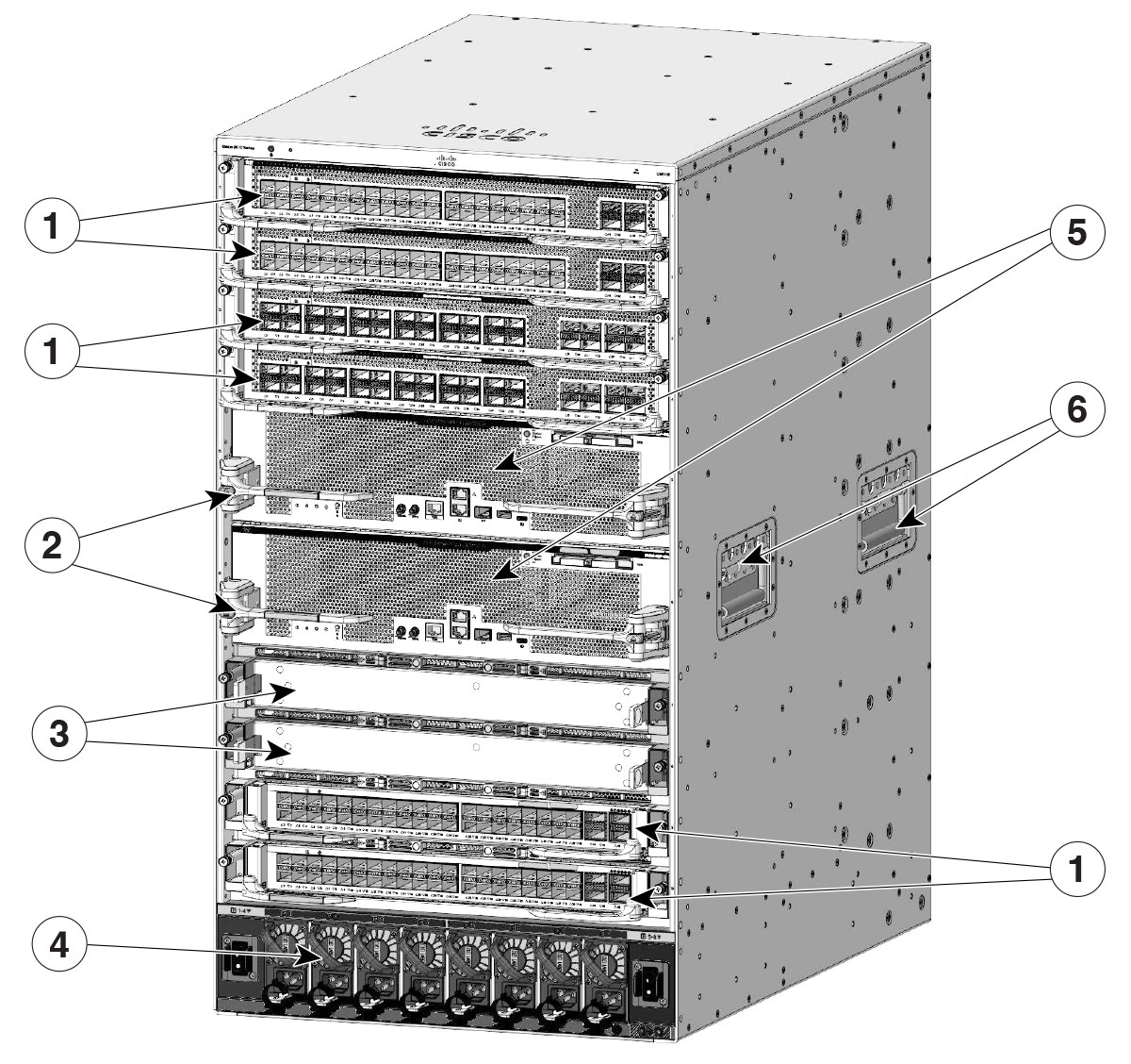
The Cisco C9610 switch is a ten-slot chassis, with two redundant supervisor module slots, eight line card slots, eight power supply modules, and four fan tray modules.
|
Feature |
Description |
|---|---|
|
Product ID |
Cisco C9610 Series Smart Switch |
|
Chassis |
Has ten horizontal slots. Slots are numbered 1 to 10 from top to bottom. |
|
Supervisor modules |
Accommodates two supervisor modules. The supported models are
|
|
Line cards |
Accommodates up to eight line cards. The supported line cards are
With the line card adapter C9610-LC-ADPT, the switch supports these line cards:
For more information about installing a line card, see the Cisco C9610 Series Line Card Installation Note. |
|
Fan tray assembly |
Provides 4 rear serviceable and hot-swappable fan tray with 6 fans per tray. |
|
Power supplies |
Has 8 power supply slots that supports up to 8 AC or DC power supply modules. |
|
Backplane |
Provides 6.4Tbps bandwidth per slot. |
|
1 |
Line card slots |
4 |
Power supply modules |
|
2 |
Supervisor module latch |
5 |
Supervisor module slots |
|
3 |
Line card slots covered with blanks |
6 |
Chassis handholds |
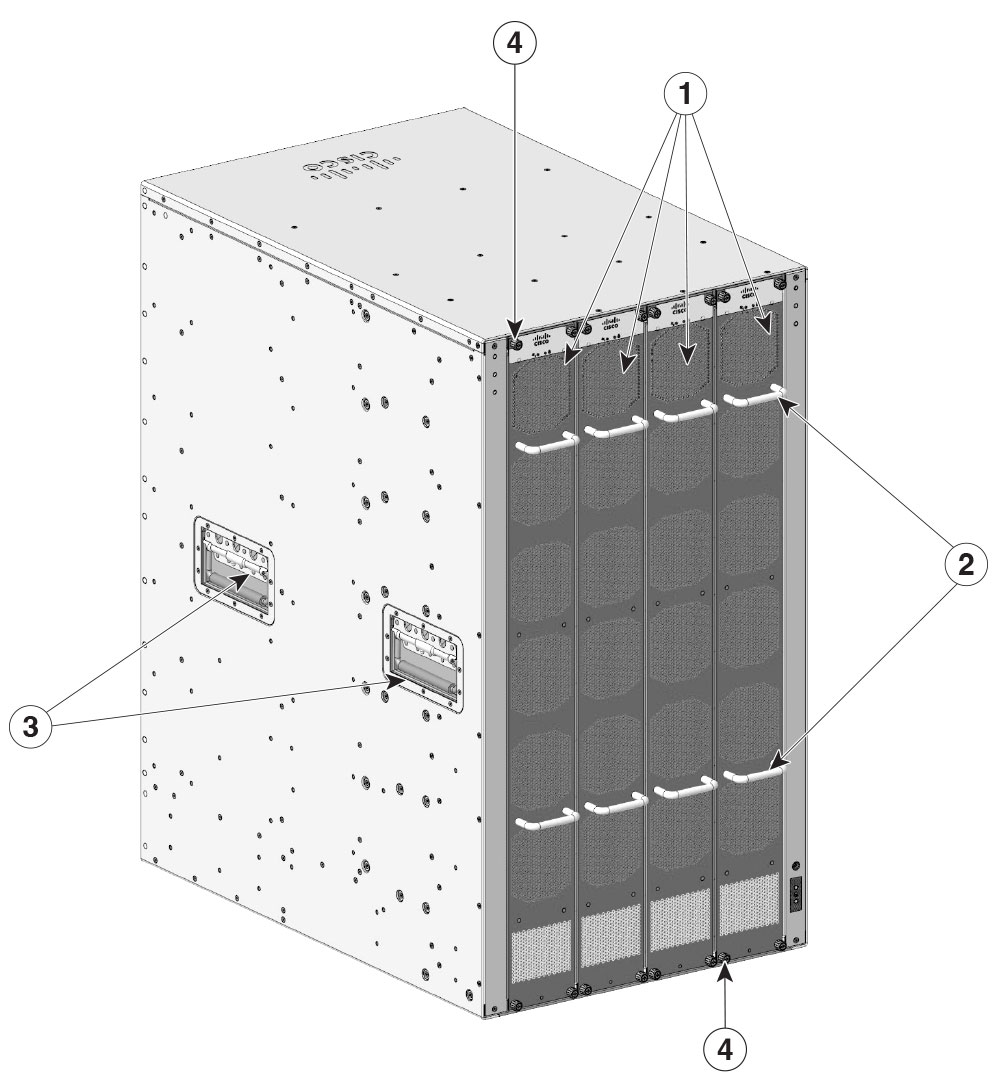
The figure shows a rear view of the chassis, with the major components identified.
|
1 |
Fan trays |
3 |
Chassis handholds |
|
2 |
Fan tray assembly handles |
4 |
Captive installation screws |
Fan tray assembly
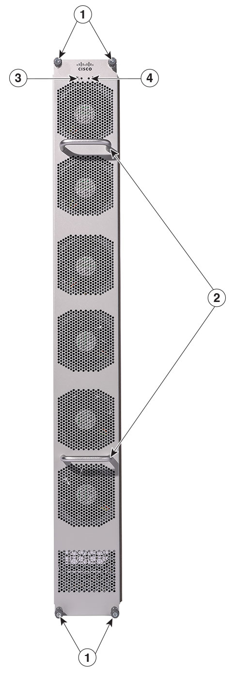
The Cisco C9610 Series Smart Switches consist of four fan trays. Each fan tray (C9610-FAN) consists of six fans and a connector. If one of the fans is not functioning and you need to replace the fan, you must order a fan tray; individual fans cannot be ordered.
When the system is powered on, all four fan trays must be present, or the system will not initialize.
The fans cool the entire chassis and interface with environmental monitors to trigger alarms when conditions exceed thresholds. Fan trays provide cooling critical for the switch operation, which could otherwise result in the switch being nonoperational or cause permanent damage to modules or components.
The features of a Cisco C9610 fan tray include
- four fan tray slots in the rear panel of the chassis.
- six 80 x 80 x 80 mm fans per tray.
- fan tray modules are installed from the rear to enable front-to-back airflow.
- optimizes the fan-speed for temperature and pressure, and maintains the minimum fan speeds that the chassis requires, in ambient conditions.
This figure shows C9610-FAN with the major components identified.
|
1 |
Captive installation screws |
3 |
Fan tray status LED |
|
2 |
Fan tray handles |
6 |
Blue beacon LED for the fan tray |
Fan high availability
To ensure high availability, the system responds to fan failures by either minimizing the impact or by compensating and operating at a worst case scenario specification.
-
Boot up: When you power on the switch, all four fan trays must be present, or else, the system will not boot, and the console displays this override message.
"[HWMSG] FAN_ABSENT: Shutdown now" -
Runtime: During system runtime if one fan tray is removed from the chassis, the system will still operate; however, the console displays this warning message, and the show hardware led command output will display the system and chassis fan tray status LEDs as red.
*Aug 12 09:10:43.627 UTC: %CMRP_PFU-2-FAN_POLICY_CRITICAL: Chassis 1 R0/0: cmand: SYSTEM FAN POLICY Critical : MAJOR ALARM - One Fantray Missing!! -
If you remove two or more fan trays from the chassis, a 180 seconds countdown starts. The console displays this override message
and the system is shut down after 180 seconds.*Jun 16 09:40:07.975: %CMRP_PFU-1-FAN_POLICY_ALERT: R0/0: cmand: SYSTEM FAN POLICY Alert : FAN policy shutdown with reason CRITICAL ALARM: Two or more Fantrays missing!!. Restore working FAN or system will be shutdown in 180 seconds
Thresholds, alarms, and abnormal acoustic conditions
If two or more fans fail, you must replace the fan tray within 180 seconds or power down the system. If the temperature exceeds the shutdown threshold, software powers the system down. When the fan trays operate at full speed, increased noise levels can be expected.
The fan trays may operate at 90% of the maximum speed in these circumstances:
- If two or more fans have failed.
- If the ASIC thermal sensors hit major, critical, or shutdown thresholds.
- If one fan tray is removed (with or without additional fan failures).
- Due to high ambient temperature.
Power supply modules
The switch chassis has eight redundant power supply slots that operate with one to eight power supply modules. The chassis supports field-replaceable AC-input and DC-input power supply modules.
The power supply modules generate 12 VDC output power and distribute it to the line cards and supervisor modules. The power supplies distribute power to all slots using an internal bus-bar based power distribution mechanism. All power supply modules have internal fans and support front-to-rear airflow.
|
Part number (add = for spare) |
Description |
|---|---|
|
C9600-PWR-2KWAC (=) |
Cisco 9600 Series 2000W AC power supply |
|
C9600-PWR-2KWDC (=) |
Cisco 9600 Series 2000W DC power supply |
|
C9600-PWR-3KWAC (=) |
Cisco 9600 Series 3000W AC power supply |
AC power supply modules
Cisco C9610 Series Smart Switches support both 2000W AC and 3000W AC power supply units (PSUs).
*Jan 7 12:07:52.924 IST: %CMRP_PFU-2-PSU_MIX_PWR_CAPACITY: R0/0: cmand:
Power supplies of mixed power capacity is not a supported configuration.
This can lead to unstable behavior or system reload, please connect power supplies
of the same power capacity to avoid any issues.
The 2000W AC is Platinum-rated and meets the Platinum certification standard for energy efficiency. Platinum-based PSUs typically provide around 92% efficacy at 50% load, with only 8% lost as heat.
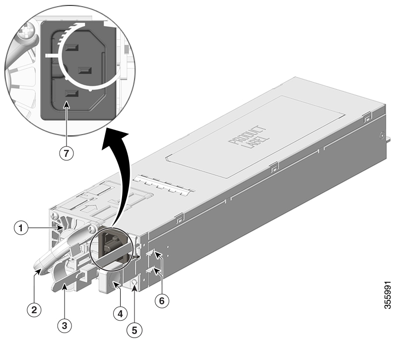
|
1 |
PSU fan |
5 |
Status LED |
|
2 |
Release handle |
6 |
Retainer clips |
|
3 |
Power cord retainer |
7 |
Power cord connector |
|
4 |
Release latch |
- |
- |
The 3000W AC power supply module is Titanium-rated, and refers to a power supply that meets the Titanium efficiency standard. This standard ensures minimal energy loss during power conversion, and is at present, the highest efficiency rating available for server power supplies. Titanium-based power supplies typically provide 96% or higher efficiency at 50% load, and up to 94% at full load.
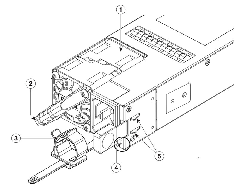
|
1 |
PSU fan |
4 |
Status LED |
|
2 |
Release handle |
5 |
Latch shrapnel |
|
3 |
Cable tie |
- |
- |
The features of the AC power supply module are
- self-cooling, with a minimum airflow of 17 cubic feet per minute (CFM) at 100 percent load,
- a single-phase source AC. Source AC can be out-of-phase between multiple power supplies or multiple AC-power plugs on the same power source because all AC power supply inputs are isolated,
- a release latch and cord-retention mechanism on the front panel of the module, to avoid accidental removal of the module or the attached power cord, and
- redundant and combined configuration modes.
A single (non-redundant) or a dual (redundant) power supply configuration, can support these loads.
| PID |
Input voltage (VAC) |
Output power in Watts |
|---|---|---|
|
C9600-PWR-2KWAC |
110 VAC |
1050W |
|
220 VAC |
2000W |
|
|
C9600-PWR-3KWAC |
110 VAC |
1500W |
|
220 VAC |
3000W |
DC power supply modules
The section describes the 2000W DC power supply module supported on Cisco C9610 series smart switches.

|
1 |
PSU fan |
4 |
LED |
|
2 |
Release handle |
5 |
Power cord connector |
|
3 |
Release latch |
- |
- |
The features supported by the DC power supply module are
- self-cooling, with a minimum airflow of 9.5 cubic feet per minute (CFM) at 100% load,
- a release latch mechanism on the side of the module, to avoid accidental removal of the module,
- a DC-input reversal protection such that the unit will survive this condition up to the full input voltage rating, and
- redundant and combined configuration modes.
A single (non-redundant) or a dual (redundant) power supply configuration supports these loads.
| PID |
Input voltage (VDC) |
Output power |
|---|---|---|
|
C9600-PWR-2KWDC |
-40 to -60 VDC (with extended range to -72 VDC) |
2000W |
Power supply modes
Cisco C9610 series smart switches offer redundant and combined configuration modes for power supplies. In both modes, the load is equally distributed among the power supplies.
The system load and number of power supply modules installed determine the power level required by the system from each power supply module, and consequently, the suitable power supply mode. For system power budgeting estimates and to determine power supply requirements, use the Cisco Power Calculator .
To configure a power supply mode, enter the power redundancy-mode command in global configuration mode. If you do not configure a mode, the default mode applies. The default mode is combined mode.
Combined mode
The system operates with one to eight power supply modules. The power available to the system is the sum of the power outputs of all the power supply modules in the chassis multiplied by the share ratio. All available power supply modules are active and sharing power, and can operate at up to 100 percent capacity. Additional power supply units operate at 97 percent capacity.
In combined mode, you can use a combination of AC or DC power supplies, provided the AC input voltage is 220V and the power supplies are of equal wattage. However, you cannot combine an AC power supply unit of 110V input with an AC power supply unit of 220V input.
Total combined mode power = P + (N-1) * (P-60)
- where P is the power output of one of the power supply units and N is the number of power supply modules used.
- and 60W is the power wastage for every additional PSU, other than the first one; regardless of the PSU capacity or input voltage.
 Note
NoteIn case of a failure in combined mode, each operational power supply increases its output. If the output power does not meet the system requirements, all the operational power supply modules may be overloaded and go into overcurrent shutdown. All system power is then lost.
This table provides details about the power output in combined mode.
| PID |
Input voltage |
One PSU |
Two PSUs |
Three PSUs |
Four PSUs |
Five PSUs |
Six PSUs |
Seven PSUs |
Eight PSUs |
|---|---|---|---|---|---|---|---|---|---|
|
C9600-PWR-2KWAC |
110V |
1050W |
2040W |
3030W |
4020W |
5010W |
6000W |
6990W |
7980W |
|
220V |
2000W |
3940W |
5880W |
7820W |
9760W |
11700W |
13640W |
15580W |
|
|
C9600-PWR-3KWAC |
110V |
1500W |
2940W |
4380W |
5820W |
7260W |
8700W |
10140 |
11580W |
|
220V |
3000W |
5940W |
8880W |
11820W |
14760W |
17700W |
20640W |
23580W |
Redundant N+1 mode
In a redundant configuration, a given power supply module can either be active, or in a standby mode. You can configure either N+1 mode or N+N mode, where N is the number of active power supply modules.
In N+1 mode, N is the number of active power supply modules and +1 is the power supply module configured as the standby module.
When you configure the switch with N+1 redundancy, the Cisco IOS XE software ensures that there is a standby power supply available, and that sufficient power is available with the active power supply modules (N). All the power supplies including the active and standby shares the load equally. However, with a standby power supply installed, the system ensures that the additional output power available with a standby is always reserved for use in case of a failure. If the power supply mode is set to redundant and the total active output power is not sufficient to meet the power requirements, the switch will not enter redundant mode.
You can use a combination of AC or DC power supplies provided the AC input voltage is 220V and the power supplies are of equal wattage. However, you cannot combine an AC power supply unit of 110V input with a AC power supply unit of 220V input.
This table provides details about the power output in N+1 redundant mode.
| PID |
Input voltage |
Two PSUs |
Three PSUs |
Four PSUs |
Five PSUs |
Six PSUs |
Seven PSUs |
Eight PSUs |
|---|---|---|---|---|---|---|---|---|
|
C9600-PWR-2KWAC |
110V |
1050W |
2040W |
3030W |
4020W |
5010W |
6000W |
6990W |
|
220V |
2000W |
3940W |
5880W |
7820W |
9760W |
11700W |
13640W |
|
|
C9600-PWR-3KWAC |
110V |
1500W |
2940W |
4380W |
5820W |
7260W |
8700W |
10140W |
|
220V |
3000W |
5940W |
8880W |
11820W |
14760W |
17700W |
20640W |
Redundant N+N mode
In N+N mode, N number of power supply modules are configured as active, and N number of power supply modules are configured as standby. For each active module, there is a standby power supply module.
| PID |
Input voltage |
Two PSUs |
Four PSUs |
Six PSUs |
Eight PSUs |
|---|---|---|---|---|---|
|
C9600-PWR-2KWAC |
110V |
1050W |
2040W |
3030W |
4020W |
|
220V |
2000W |
3940W |
5880W |
7820W |
|
|
C9600-PWR-3KWAC |
110V |
1500W |
2940W |
4380W |
5820W |
|
220V |
3000W |
5940W |
8880W |
11820W |
Understanding LEDs
This section describes the LED positions and colors in the supervisor module, fan tray, line cards, and power supply modules.
Chassis LEDs
This table describes the C9610 series chassis LEDs and the status.
|
LED type |
LED position or color |
Description |
|---|---|---|
 BLUE BEACON |

Blue |
Identifies the chassis. You can switch on the LED through the software. |
|
Blink fast |
Indicates that the module requires attention. Configured by the user. The LED blinks at the rate of 1.2 seconds. |
|
|
Blink slow |
Indicates that the module requires attention. Configured by the user. The LED blinks at the rate of 0.6 seconds. |
|
|
Off |
Indicates that the module does not require any attention. |
|
|
FAN |

Green |
All fans are running and the fan tray is operating normally. |

Amber |
One fan is not running. |
|

Red |
Two or more fans are not running. |
|
|
Off |
Fan tray is not getting any power. |
Supervisor module LEDs
This table describes the supervisor module LEDs and the status.
|
LED type |
LED position or color |
Description |
|---|---|---|
 STATUS |
Green |
Indicates that all diagnostic tests have passed after image booting. |
|
Amber |
Indicates a major environmental warning. |
|
|
Red |
Indicates a fault in the module due to parity error or failed diagnostic tests or hardware failure. |
|
|
Off |
Indicates that the supervisor module is disabled or is not powered up. |
|
|
BLUE BEACON |
Blue |
Identifies the supervisor module receiving the beacon signal. You can switch on this beacon through the software. |
|
Blink fast |
Indicates that the module requires attention. Configured by the user. The LED blinks at the rate of 1.2 seconds. |
|
|
Blink slow |
Indicates that the module requires attention. Configured by the user. The LED blinks at the rate of 0.6 seconds. |
|
|
Off |
Indicates that the module does not require any attention. |
|
 SYSTEM |
Green |
Indicates that the environmental monitors are normal. |
|
Amber |
Indicates a minor fault such as partial power supply or fan failure. |
|
|
Red |
Indicates a major fault. For example, situations where the temperature of the supervisor module exceeds the critical threshold. |
|
 ACTIVE |
Green |
Indicates that the supervisor module is operational and is functioning as the active supervisor (in redundant supervisor module configurations). |
|
Amber |
Indicates one of the following:
|
|

Blinking amber |
Indicates Graceful Insertion and Removal (GIR) of the module. |
|
|
Solid State Drive (SSD) LED |
Green |
SSD is installed and working. |
|
Amber |
SSD can be removed safely. To unmount the SSD, press the Eject/Status LED button, and wait for the LED to change the color to Amber. |
Fan tray LEDs
This table describes the light-emitting diode (LED) information for the fan trays. These LEDs available on the top of the front panel of the chassis display the status of the four fan trays on the rear panel.
|
LED type |
LED position or color |
Description |
|---|---|---|
|
STATUS |
Off |
Fan tray is not receiving any power. |
|
Green |
All fans are running and the fan tray is operating normally. |
|
|
Amber |
One fan is not running and the fan tray is not operating properly. |
|
|
Red |
Two or more fans are not working. |
|
|
LOCATE or Blue Beacon |
Blue |
Indicates that the module requires attention. Each of fan trays have a blue beacon, and you can switch on this beacon through the software. |
|
Blink fast |
Indicates that the module requires attention. Configured by the user. The LED blinks at the rate of 1.2 seconds. |
|
|
Blink slow |
Indicates that the module requires attention. Configured by the user. The LED blinks at the rate of 0.6 seconds. |
|
|
Off |
Indicates that the module does not require any attention. |
Line card LEDs
This table describes the line card LED position or color.
|
LED type |
LED position or color |
Description |
|
|---|---|---|---|
|
Blue beacon |
Blue |
Indicates that the module requires attention. Provisioned by the administrator of the system. |
|
|
Blink fast |
Indicates that the module requires attention. The LED blinks at a rate of 0.6 seconds. |
||
|
Blink slow |
Indicates that the module requires attention. Configured by the user, the LED blinks at a rate of 1.2 seconds. |
||
|
Off |
Indicates that the module does not need any attention. |
||
|
Status LED |
Green |
Indicates that all diagnostic tests have passed and the module is operational. |
|
|
Red |
Indicates major environmental alarms, if the module is online. |
||
|
Amber |
Indicates minor environmental alarms, if the module is online. |
||
|
Off |
Indicates that the module is disabled or is not powered up. |
||
 Port LED |
Green |
Port link is up. |
|
|
Amber |
Port link is disabled, that is, administratively down. |
||
|
Off |
No signal is detected, the link is down, or the port is not connected. |
||
|
Alternating Green and Amber |
Indicates port beacon. |
||
|
Blinking Amber |
Indicates link faults such as excessive collision errors. |
||

Blinking Green |
Indicates traffic on the port. |
||
| Traffic utilization | Blinking rate | ||
|
Less than 5% |
Nil |
||
|
Between 5% and 30% |
At a rate of 1.2 seconds. |
||
|
Between 30% and 70% |
At a rate of 0.4 seconds. |
||
|
More than 70% |
At a rate of 0.2 seconds. |
||
Power supply module LEDs
This table describes the power supply module LED position and color.
|
LED position or color |
Description |
|
|---|---|---|
|
STATUS |
Green |
Indicates that the power supply module is switched on with outputs 12V main and 12Vstandby available and in regulation. |
|
Amber |
Indicates one of the following:
|
|
|
1Hz blinking Amber |
Indicates warning events such as a power supply module that continues to operate in high temperature or high power and a fan that runs slow, and so on. |
|
|
1Hz blinking Green |
Indicates bootloading mode. |
|
|
2Hz blinking Green |
Indicates that power switch is turned off with AC/DC input power available or that the power supply is in standby mode. |
|
|
Off |
Indicates one of the following:
|