All-Active Mode Overview

EVPN multihoming overview

The Ethernet VPN (EVPN) multihoming is RFC 7432, RFC 8365 based industry-standard Layer 2 multipath solution solving various traditional networking protocol challenges impacting scale, performance and resiliency. It is an advanced networking technology designed to provide high availability, Border Gateway Protocol (BGP) based Layer 2 loop-free network, and efficient load balancing in modern enterprise campus networks.

A pair of Cisco Catalyst 9000 series switches can connect to downstream Layer 2 or Layer 3 network device with local physical connection binding into single logical EtherChannel configured in Layer 2 trunk or access mode. With industry-standard non-blocking architecture, any downstream networking devices such as, Ethernet Switch, Wireless LAN Controller (WLC), firewalls, servers and hosts can be dual-homed.
EVPN multihoming key benefits

EVPN multihoming technology was introduced on Cisco Catalyst 9000 series switches in Cisco IOS XE 17.18.2, delivering a highly flexible and extensible deployment solution for global enterprise customers.

The key technology architecture benefits of Cisco Catalyst 9000 series switches combined with the advanced Cisco IOS XE software capabilities enable best of both worlds. Enterprise network administrators can implement EVPN multihoming within their existing traditional Layer 2 or Layer 3 network designs while laying a practical and gradual foundation for evolving towards modern, secure, fabric-based virtual networks.

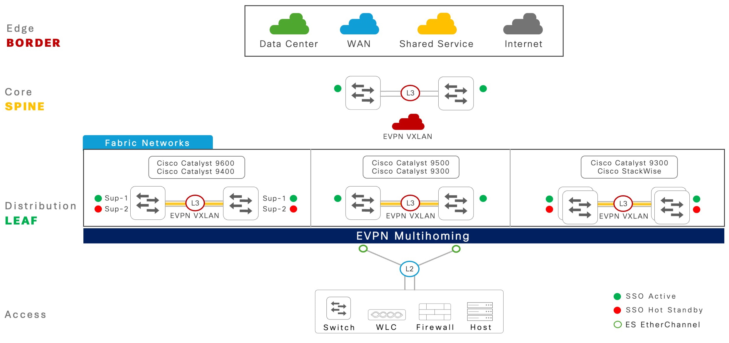
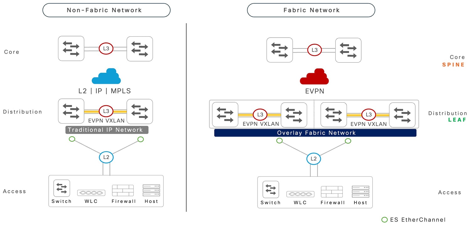
The following illustration shows the EVPN multihoming solution for Cisco Catalyst 9000 series switches in two key flexible deployment models.

Figure 1. EVPN multihoming enterprise campus deployment model

EVPN multihoming enterprise campus deployment model

With flexible deployment model support, EVPN multihoming provides significant technological benefits to support enterprise-grade networking requirements.

  • Industry-standard Layer 2 multipath: RFC 7432 and RFC 8365-defined Layer 2 multipath technology with BGP control-plane eliminates the vendor proprietary complex solutions.

  • Flexible architecture: Purpose-built solution supports a wide range of networking use-cases for traditional Layer 2 and Layer 3, to modernized secure campus fabrics enabling network-wide, two-tier virtual network segmentation and extensions.

  • Distributed planes: A fully distributed architecture where each system maintains its own scalable and resilient control plane, independent management plane configuration, and software versions provide more resilience with synchronized data-plane between paired systems.

  • Increased performance: Non-blocking Spanning Tree Protocol (STP), Layer 2 loop-free network combined with advanced load-sharing technique assist in increasing forwarding capacity and improving application experience.

  • Seamless integration: Least disruptive integration in classic Layer 2 networks with a wide range of networking device types that support link-bundling capabilities. Flexible and seamless integration with existing core network system without a forklift architecture change.

  • Resilient: Deterministic fault detection and recovery technique during various types of planned and unplanned failure conditions, which reduces the Mean Time to Repair (MTTR) and increases the network reliability with a higher Mean Time Between Failure (MTBF).

    A pair of modular-class platforms with redundancy (Quad-Sup NSF and SSO): Provides non-stop business communication in maintaining network availability and forwarding throughput capacity during software upgrades and other unplanned failure events.

Cisco Catalyst 9000 Series platform support matrix

EVPN multihoming is supported on a wide range of modular and fixed Cisco Catalyst 9000 series switch models. The system can be deployed in standalone or resilient mode, providing single network and device-level redundancy.

This table provides a list of supported Cisco Catalyst 9000 series platforms with the system mode.

Table 1. EVPN multihoming platform support matrix

Cisco Catalyst 9000 series switch model

System mode

Modular platforms

  • Catalyst 9400 Series Supervisor 1

  • Catalyst 9400 Series Supervisor 2

  • Catalyst 9400 Series Supervisor 2XL

  • Catalyst 9600 Supervisor 1

  • Single supervisor: non-redundant

  • Dual supervisor: redundant

Fixed platforms

Catalyst 9300 Series

  • Standalone: non-redundant

  • StackWise: redundant

Catalyst 9500 High Performance Series

Standalone: non-redundant

Restrictions for EVPN multihoming in all-active mode

This section lists the deployment restrictions for multihoming in all-active mode.

  • EVPN multihoming is not supported on Cisco Catalyst 9500-X series switches, Catalyst 9600 Supervisor 2, Cisco C9350 series smart switches, and Cisco C9610 series smart switches.

  • Combined mode with StackWise Virtual and EVPN multihoming on single switch is not supported on Cisco Catalyst 9400 series switches, Cisco Catalyst 9500-High Performance series switches, and Cisco Catalyst 9600 series switches.

  • EVPN multihoming for non-fabric and fabric networks with IPv6-only underlay network is not supported.

  • EVPN multihoming is not supported with Layer 2 leaf mode in centralized gateway mode fabric deployments.

  • EVPN multihoming In-Service Software Upgrade (ISSU) from a release prior to Cisco IOS XE 17.18.2 is not supported on Cisco Catalyst 9400 series and Cisco Catalyst 9600 series modular platforms with redundant supervisors.

  • Anycast gateway (global or VRF-enabled) SVI with First Hop Redundancy Protocol (FHRP) protocol is not supported.

  • Resilient Ethernet Protocol (REP) on Layer 2 Ethernet segment ports is not supported.

  • Private VLAN (PVLAN) on Layer 2 Ethernet segment ports is not supported.

  • DHCP snooping and ARP inspection on VLAN IDs mapped on logical Ethernet Segment EtherChannel trunk port is not supported.

EVPN scale matrix in all-active mode

This section describes the system-wide Layer 2 interface and table entry scale limits for EVPN multihoming enabled on Cisco Catalyst 9000 series switches in fabric mode.

Table 2. EVPN multihoming platform scale matrix

EVPN multihoming segment scale matrix

Scale count

Ethernet segment switch per redundancy group

2

Ethernet segment Port Channel interface

48

Number of VLANs

200

MAC address

10,000

IPv4 address

10,000

IPv6 address

20,000

IP VRF

25

EVPN multihoming technology overview

The legacy networking protocols in enterprise campus networks have been a challenge for IT organizations.

The challenges include difficulty in eliminating Spanning Tree Protocol (STP) that can lead to inefficient network topologies, restrictions in traditional Layer 2 designs that limit the network switching capacity, lack of deterministic reliability that makes it a challenge to support real-time mission-critical applications, insufficient support for mobility in wireless and legacy application environments, and increased complexity in network management and troubleshooting.

This section provides a brief overview of the advanced industry-standard EVPN multihoming technology for traditional Layer 2 and Layer 3 networks. Each subsection focuses on various technology components enabling loop-free, high-performance and resilient Layer 2 networking solutions.

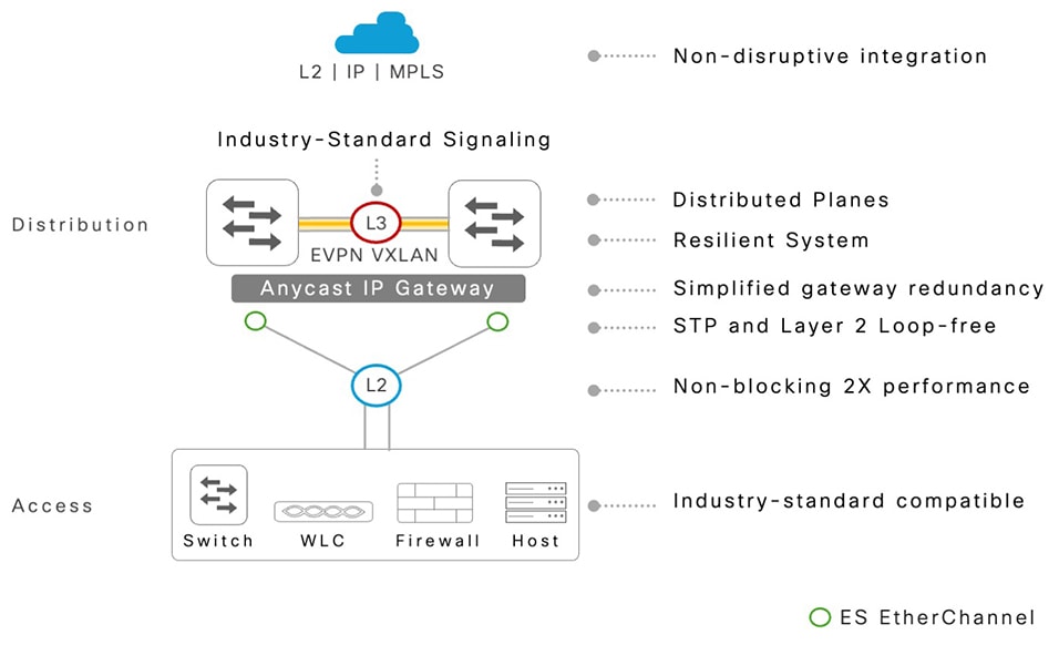
The following illustration captures the key benefits of EVPN multihoming technology for simplified and resilient enterprise campus networks.

Figure 2. EVPN multihoming technology benefits
Benefits of EVPN multihoming technology

Refer to the Terms and definitions section for the description and purpose of acronyms.

Network system components

The EVPN multihoming technology comprises directly attached networking systems through traditional Layer 2 ports in trunk or access mode. The Cisco Catalyst 9000 series switches are required to provision in EVPN multihoming mode to provide a loop-free Layer 2 multipath EtherChannel to any type of downstream network device.

Ethernet segment redundancy group

An Ethernet segment redundancy group is a physical grouping of network devices that form an EVPN multihoming network, enabling an all-active Layer 2 multipath solution.

The EVPN multihoming redundancy group consists of a single pair of Cisco Catalyst 9000 series switches, which provide physical connectivity and system-level redundancy. This architecture ensures continuous communication during both planned and unplanned failure events.

Ethernet segment switch

An Ethernet segment switch is a typical Cisco Catalyst 9000 series switch in core or distribution system configured to support the Layer 2 multihomed network with directly attached various types of Layer 2 systems.

The Ethernet Segment (ES) system can support multifunctional Layer 2 and Layer 3 networks for enterprise campus networks in classic and traditional non-fabric or modern fabric network roles. As a result, the ES switch is also known as a Provider Edge (PE) or Leaf or VTEP. Each ES switch operates and maintains fully distributed control, management, and data planes while solving legacy protocol challenges with industry-standard Layer 2 multipath solutions.


Note


Cisco Catalyst 9000 series switches in StackWise mode are considered as logical system Ethernet segment switches.


Ethernet segment switch platform and software

The EVPN multihoming technology operation between ES network devices—fixed or modular models, is no different from any of the other industry-standard networking protocols, like OSPF and BGP. A pair of ES switches can have different platform types, modules, interfaces, and so on. The ES pair switches can also have different Cisco IOS XE software versions to address stage upgrades and other conditions.

While the technology permits asymmetric platform and software versions on an ES pair, Cisco recommends a common platform and software version to deliver consistent performance and resiliency for non-disruptive business continuity during planned and unplanned failure conditions.

Ethernet segment client

The Layer 2 system is a directly attached single, dual, or multihomed connection to a pair of Cisco Catalyst 9000 series switches in an ES system. The Layer 2 ES client network can be of any device type but must follow the industry-standard Layer 2 networking technologies.

EVPN multihoming control plane

The EVPN multihoming technology is built on industry-standard, highly flexible, and proven BGP routing protocol. The BGP control plane replaces legacy STP for Layer 2 loop detection and prevention techniques.

The L2VPN EVPN address-family is a multiprotocol extension that enables a network-agnostic multihoming solution. The BGP protocol provides four key functions: discover remote neighbor and ES ID, real-time synchronization of network states, distributed forwarding rule to select local-bias rules for optimal performance, and resiliency for deterministic and efficient rapid fault-detection and recovery.

Ethernet segment

Ethernet segment (ES) is a pair of Cisco Catalyst 9000 series switches in the aggregation layer with a Layer 2 physical port that directly connects to an ES client device. It represents a single logical entity to enable loop-free, non-blocking all-active Layer 2 network connectivity.

An STP-Bridge Protocol Data Unit (BPDU) free Layer 2 network dynamically supports per-VLAN loop prevention while maximizing the network throughput to support accelerated application performance and resiliency.

Ethernet segment ID

An Ethernet segment ID is a 10-byte (00:01:01:01:01:01:01:01:01:01) identifier for each Layer 2 port that is connected to an ES client device. A common ES ID is assigned to a pair of Catalyst 9000 ES systems on the Layer 2 physical port that connects to the same Layer 2 ES client device to enable all-active EVPN multihoming.

Cisco Catalyst 9000 series switches support 3 types of industry-standard ESI ID that is either auto-generated or IT-defined and manually configured.

Anycast gateway MAC and IP addresses

A Cisco Catalyst 9000 SVI interface with anycast gateway is provisioned with a shared virtual IP address and an auto-derived shared virtual MAC address with anycast-gateway mac auto command in the global settings, on pair of EVPN multihoming switches. The unified, resolved ARP and ND addresses between the distributed Catalyst 9000 IP gateway switches support optimal data load-balancing across all available bundled links and resilient networks during planned or unplanned failures for wired and wireless endpoints.

Designated forwarder and non-designated forwarder roles

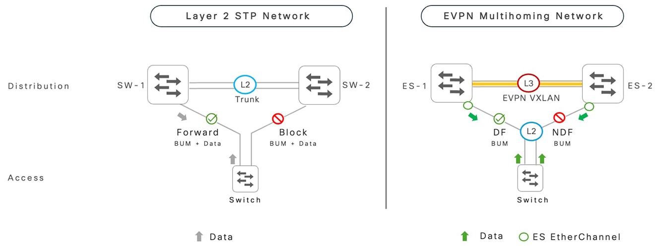
Traditionally, in Layer 2 STP-enabled networks, loop detection is achieved through a blocking link to transmit broadcast and business application data traffic. As a result, the network operates inefficiently at reduced bandwidth capacity. Additionally, protocol-based fault detection and recovery increase the network convergence time, which impacts the reliability of mission-critical applications during faults.

In EVPN multihoming-based campus networks, the same result is obtained using a very different logic. Instead of blocking links, the EVPN distinctly decouples network traffic types between broadcast categories and business applications. On a per ES port and VLAN basis, the pair of Cisco Catalyst 9000 series switches dynamically assign specific roles to forward BUM (Broadcast, Unknown Unicast, and Multicast) traffic in active and passive modes. However, business application forwarding traffic is unblocked in active-active mode.

The Catalyst 9000 series switch elected to actively forward the BUM traffic on a shared ES EtherChannel interface is known as designated forwarder (DF). The Catalyst 9000 series switch elected to block the forwarding of the BUM traffic on a shared ES EtherChannel interface is known as non-designated forwarder (non-DF). The dynamic DF and non-DF role assignment is automatically derived based on the internal system modulo hash algorithm, which enables auto load balancing of the BUM traffic between a pair of Catalyst 9000 switches connected to same downstream Layer 2 network access devices.

Figure 3. Designated forwarder and non-designated forwarder roles

Designated forwarder and non-designated forwarder roles

Dynamic MAC and IP learning and synchronization

EVPN multihoming networks build and maintain the Layer 2 and Layer 3 network information using the control plane, between a pair of Cisco Catalyst 9000 ES switches.

The upstream data towards the IP core network is hashed from Layer 2 network devices, the dynamic MAC, IPv4, and IPv6 host addresses synchronized using the BGP control plane in real time between both the ES switches.

The common MAC or IP forwarding tables enable high performance and fully-distributed local forwarding while pre-programming the inter-ES Layer 2 VXLAN tunnel to bridge the downstream Layer 2 network traffic as the last-resort interface to reroute the data plane rapidly, upon local path failure, without relying on data-plane flooding.

IGMP join and leave synchronization

The incoming Internet Group Management Protocol (IGMP) messages from multicast host receivers are locally processed by the connected Cisco Catalyst 9000 ES switches. The IPv4 or IPv6 multicast group-to-IP membership information is synchronized between the ES switches by using an extended BGP control plane that supports consistent multicast state across the multihomed Ethernet segments.

The Catalyst 9000 ES switch with a VLAN in the DF role transmits egress multicast traffic towards the receiver. The peer non-DF ES switch suppresses duplicate multicast frames to prevent loops and undesired multicast replication. This enables EVPN multihoming to support symmetric unicast or multicast application performance and resiliency during planned or unplanned failure events.

EVPN multihoming for non-fabric networks

EVPN multihoming in Cisco Catalyst 9000 series switches provides a flexible deployment solution for global enterprise customers to retain their traditional Layer 2 or Layer 3 networks in upstream core networks. Such network deployment option is also known as non-fabric network.

EVPN multihoming in fabric networks

Modern enterprise campuses require a secure fabric networking solution that seamlessly supports large-scale virtual and logical networks over a robust physical network infrastructure. EVPN multihoming-based networks offer a simplified and resilient architecture evolving from legacy STP protocol-based enterprise campus networks to a non-blocking Layer 2 fabric.

The EVPN VXLAN-enabled fabric core networks introduce new possibilities for EVPN multihomed Layer 2 networks by enabling secured wired and wireless segmented and extended networks that address critical technical and business requirements.

The following illustration displays EVPN multihoming in fabric networks

Figure 4. EVPN multihoming in fabric networks

EVPN multihoming for fabric networks

Single unified BGP control plane

Enterprise campuses can be designed and deployed using a single unified BGP control plane that addresses the traditional Layer 2 and Layer 3 networking requirements at the access layer while supporting a modern fabric network at the core. The unified BGP control plane simplifies network operations by distinctly managing multi-domain routing and bridging functions, enabling seamless integration of the access and core networks.

BGP EVPN multihoming-based networks represents a shift from the traditional flood-based networks to control-plane driven architecture that supports non-blocking and resilient enterprise campus networks. Host addresses—including the MAC, IPv4 or IPv6, multicast—are statefully discovered and synchronized across peer systems, enabling all-active data forwarding in BGP EVPN multihoming networks.

As the BGP control plane role expands into traditional networks, processing demands may increase due to additional BGP prefix tables supporting EVPN multihoming auto-generated prefixes.

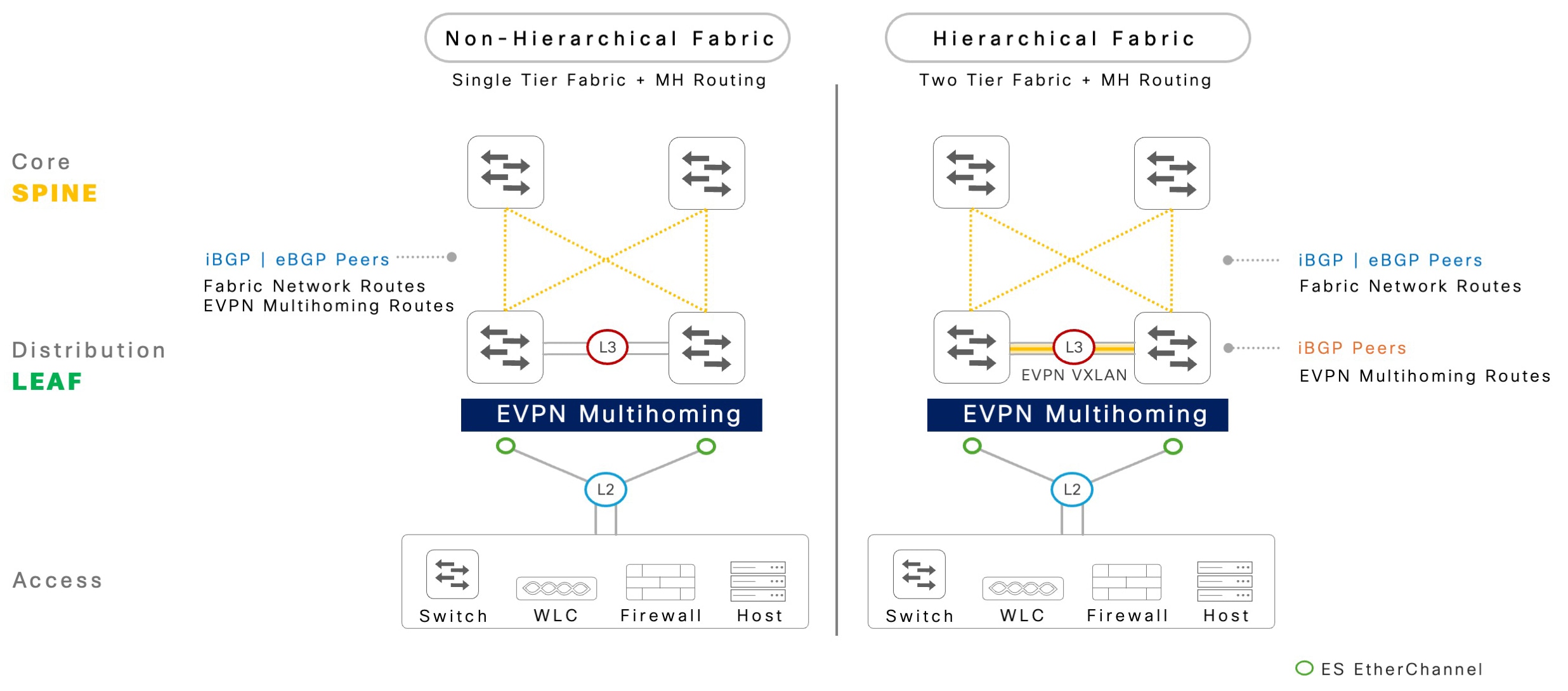
Cisco Catalyst 9000 series switches support both standard non-hierarchical and hierarchical BGP peering mode between leaf and spine devices, facilitating the exchange of fabric and EVPN multihoming network prefixes.

To address scalability and performance requirements, Catalyst 9000 series switches can implement a two-tier hierarchical control-plane network in large deployments.

Figure 5. BGP peering alternatives for fabric networks

BGP peering alternatives for fabric networks

Non-hierarchical fabric networks

The general non-hierarchical BGP EVPN VXLAN network implementation follows a standard single tier BGP peering model where all fabric devices peer directly with each other to dynamically exchange routes and build the VXLAN forwarding tunnels.

The EVPN multihoming-enabled non-hierarchical fabric network implementation follows a standard iBGP or eBGP peering model between the spine and EVPN multihoming-enabled leaf or border system.

In large scale enterprise campus network environments, spine layer devices require additional resources such as processing power and memory to handle standard fabric host information, such as MAC addresses, MAC/IP bindings and network prefixes (IPv4/IPv6) along with EVPN multihoming auto-generated routes received from each leaf or border system.

Hierarchical Fabric Networks

Hierarchical and structured networking is fundamental to supporting scalable and resilient campus networks, and EVPN multihoming-based fabric networks follow hierarchical BGP routing design principles for better scalable networking solutions.

The two-tier BGP peering in EVPN multihoming networks assists in subdividing route management between peers by separating Layer 2 networking from scalable network connectivity towards the spine layer.

The iBGP peering between a pair of Cisco Catalyst 9000 series switches exchanges all auto-generated EVPN multihoming network prefixes to build reliable and scalable traditional Layer 2 networks.

Cisco Catalyst 9000 series switches in EVPN multihoming leaf role follow standard parallel iBGP or eBGP peering with a pair of spine switches advertising network prefixes based on EVPN fabric overlay network types. The conditional network prefix announcement to spine switches enables enhanced flexibility, scale, performance, and resiliency across the network.

For more information on overlay networks, refer to Hierarchical EVPN Control-Plane.

EVPN fabric overlay network types overview

BGP EVPN VXLAN provides a flexible, virtual networking solution that addresses key networking use cases by combining a wide range of overlay architectures.

Such business-driven network architectures enable multidimensional benefits for scalable and secure segmented overlay networks in EVPN multihoming networks. Network administrators can build overlay networks with a “route first” mindset that can conditionally extend IP or VLAN networks between targeted Ethernet segment network devices to meet application requirements.

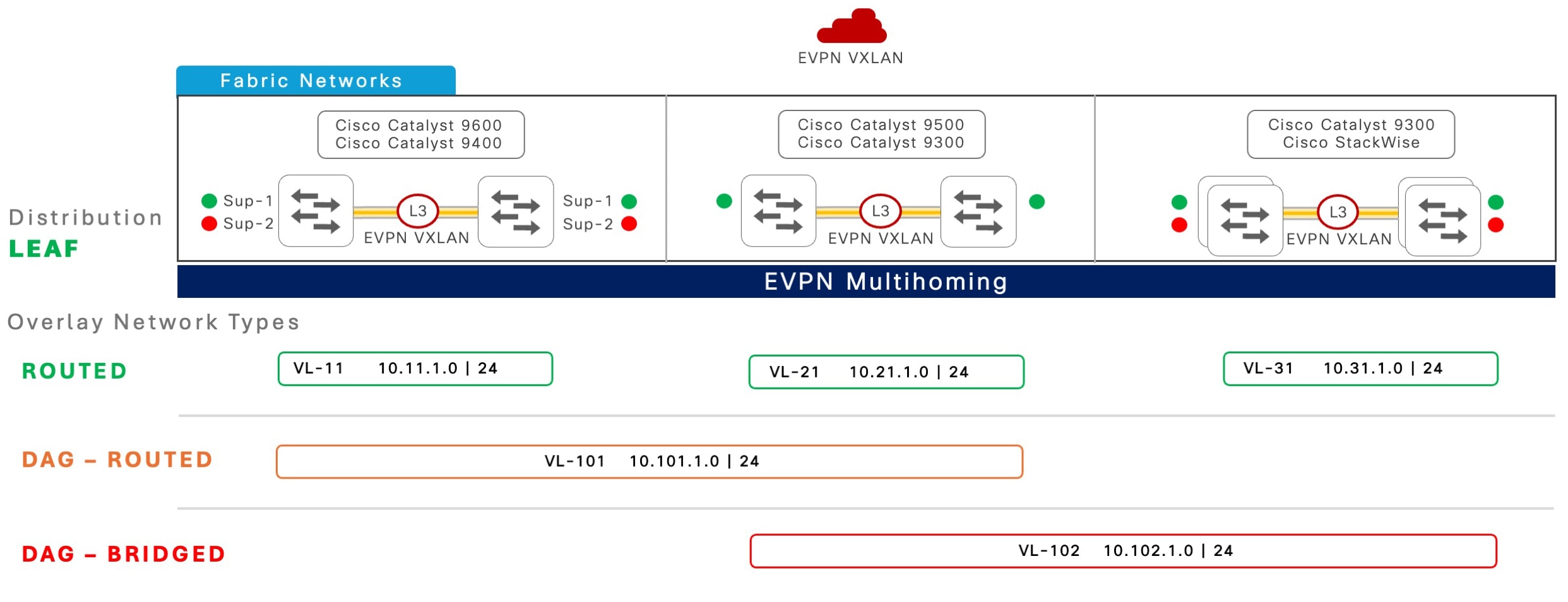
The following figure illustrates three overlay network types in EVPN multihoming networks.

Figure 6. BGP EVPN fabric overlay network types

BGP EVPN fabric overlay network types

Network administrators decide on the type of overlay networks to deploy across the fabric core based on the specific application requirements to achieve better scale and resiliency in EVPN multihoming networks.

Cisco Catalyst 9000 series switches provide a flexible solution that supports coexistence of all overlay network types within a single system. Based on technical requirements, each VLAN from an Ethernet segment EtherChannel on Cisco Catalyst 9000 series switches can be configured to support IP-routed network segmentation, conditionally stretch IP subnets, or bridge VLANs using Layer 2 flood mechanisms selectively between VLANs.

Table 3. Comparison of EVPN overlay network types

EVPN overlay network types

Routed

DAG routed

DAG bridged

Function

IP routing in core and Layer 3 segmented overlay.

Flood-free IP subnet stretch and Layer 3 segmented overlay.

Layer 2 flood stretch and Layer 3 segmented overlay.

Use case

Wired or wireless data. IT or OT endpoints

Wired or wireless data. IT or OT endpoints

Wired or wireless data. IT or OT endpoints. Non-IP endpoints
VLAN/subnet

One VLAN or subnet per distribution block

Stretched IP subnets between targeted distribution blocks

Stretched VLANs or subnets between targeted distribution blocks

Layer 2 flood boundary

Within the local Layer 2 network

Within the local Layer 2 network

Within the local Layer 2 network and across the fabric core

IP gateway

Anycast gateway per distribution block

Anycast gateway between targeted distribution blocks

Anycast gateway between targeted distribution blocks

IP subnet stretch

Not applicable

Yes—flood-free

Yes—flood-based

Seamless distributed wireless mobility

Within the local distribution block

Within the local distribution block and across targeted destination blocks

Within the local distribution block and across targeted destination blocks

Non-IP/silent host support

Within the local distribution block

Within the local distribution block

Within the local distribution block and across targeted destination blocks

Recommendation

Best scalable solution

Extends IP subnet selectively; use only if required

Extends Layer 2 flood selectively; use only if required

EVPN fabric and non-fabric network co-existence

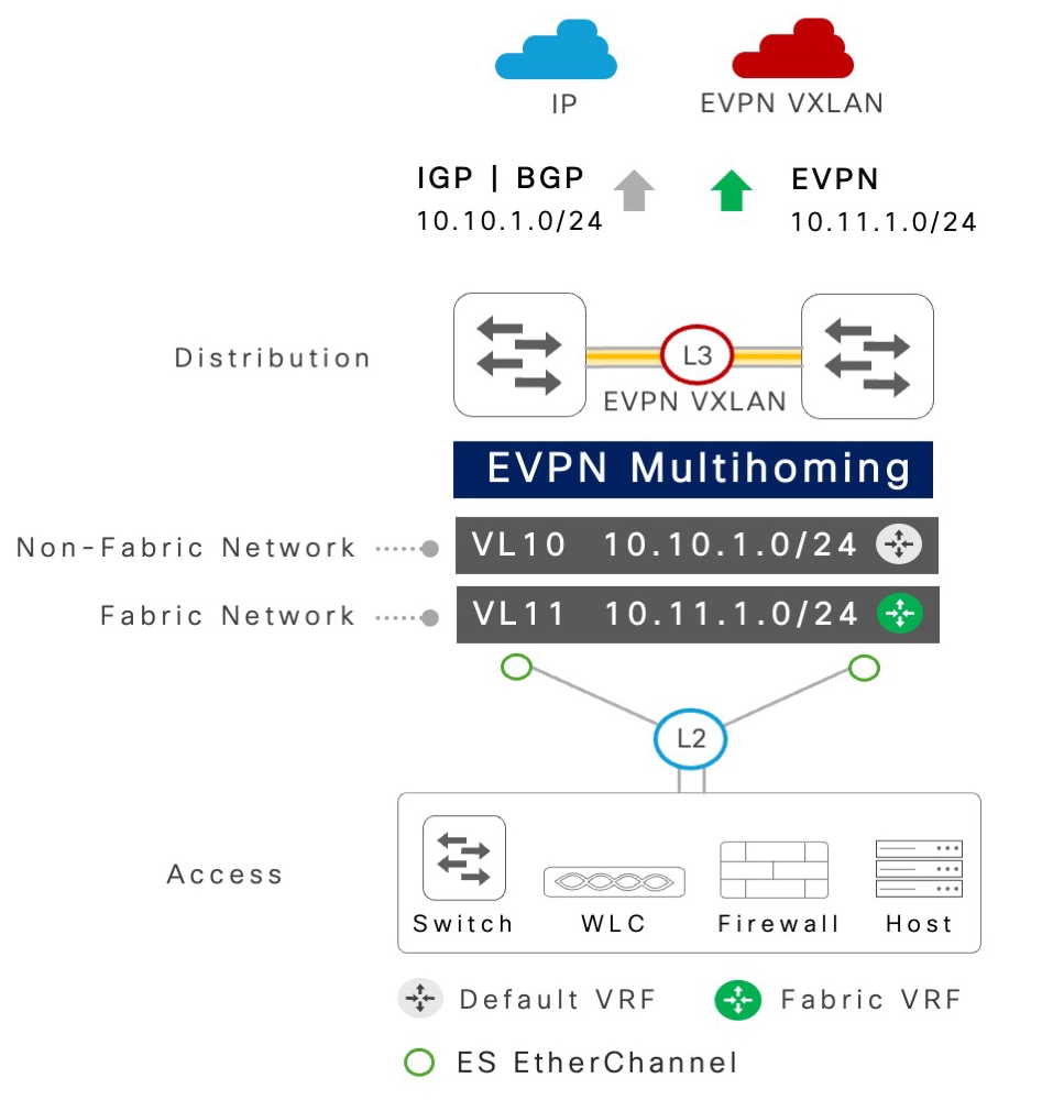
Enterprise campuses require flexible networking solutions that support both modern secure fabric networks and backward-compatible traditional Layer 2 or Layer 3 networks. Cisco Catalyst 9000 series switches with EVPN multihoming-enabled EtherChannel trunk interfaces provide this flexibility by bundling multiple VLANs, each delivering distinct networking services.

Network administrators can program some VLANs to operate traditional IP-based networks in the underlay, while mapping other VLANs to IP VRFs or MAC VRFs to route and bridge over the VXLAN fabric.

The following illustration shows a network deployment scenario with both fabric and non-fabric VLANs on EVPN multihoming-enabled networks.

Figure 7. EVPN multihoming: fabric and non-fabric network co-existence

EVPN multihoming: fabric and non-fabric network co-existence

To understand and implement EVPN multihoming for non-fabric deployments, refer to