Troubleshooting
- Getting Started
- Solving Problems at the System Component Level
- Identifying Startup Problems
- Troubleshooting the Power Supply Module
- Troubleshooting the Fan Tray
- Contacting Cisco Customer Service
- Finding Serial Numbers
Getting Started
When the initial system startup is complete, verify the following:
-
Power supplies are supplying power to the system.
-
The fan tray assembly is operating.
-
System software boots successfully.
If one or more of the above conditions are not met, use the procedures described in this chapter to isolate and, if possible, resolve the problem. If all of the above conditions are met, and the hardware installation is complete, refer to your software release notes for hardware support information and software caveats.
Solving Problems at the System Component Level
The key to success when troubleshooting the system is to isolate the problem to a specific system component. The first step is to compare what the system is doing to what it should be doing. Because a startup problem can usually be attributed to a single component, it is more efficient to isolate the problem to a subsystem rather than troubleshoot each separate component in the system.
The switch consists of these subsystems:
-
Power supplies
-
Fan tray assembly
The chassis fan tray assembly should operate whenever system power is on. You should see the FAN LED turn green and hear the fan tray assembly operating. A FAN LED indicates that one or more fans in the fan tray assembly is not operating. You should immediately contact a Customer Service representative if the fan tray assembly is not functioning properly. There are no installation adjustments that you can make if the fan tray assembly does not function properly at initial startup.
Identifying Startup Problems
LEDs indicate all system states in the startup sequence. By checking the LEDs, you can determine when and where the system failed in the startup sequence.
| Step 1 | Turn on the
power supplies. You should immediately hear the system fan tray assembly begin
to operate.
|
| Step 2 | If the startup information and system banner do not display at startup, verify that the terminal is set correctly and that it is connected properly to the console port. |
Troubleshooting the Power Supply Module
If the INPUT OK LED does not light up after you turn on the power switch, follow these steps to isolate a power subsystem problem:
| Step 1 | Verify that the INPUT OK LED on
the PSM is green.
If this unit has more than one power cord, repeat Step 1 (and all the substeps) for each PSM. For information about PSM LEDs, see Power Supply Module LEDs. |
| Step 2 | If the INPUT OK LED still fails to light up when the switch is connected to a different power source with a new power cord, the PSM is probably faulty. If a second PSM is available, install it in the second power supply bay, and contact a Cisco customer service representative for further instructions. |
| Step 3 | Verify that you have installed the power cord in the correct PEM. Each PSM and corresponding PEM is numbered. |
| Step 4 | Repeat Step 1, Step 2 , and Step 3 for all the PSMs that you have installed. |
If you are unable to resolve the problem, or if you have determined that either a power supply or a backplane connector is faulty, contact a Cisco customer service representative for instructions.
Troubleshooting the Fan Tray
To isolate a fan tray problem, follow these steps:
| Step 1 | Verify that the FAN LED on the
fan tray is green.
If the FAN LED is not green, see Solving Problems at the System Component Level to determine whether or not the power subsystem is functioning properly. For information about fan tray LEDs, see Fan Tray LED. |
| Step 2 | Check to determine if the FAN LED is red. If the FAN LED is red,
the fan tray is not seated in the backplane or has malfunctioned. Perform the
following
tasks:
|
Contacting Cisco Customer Service
If you are unable to solve a startup problem after using the troubleshooting suggestions in this chapter, contact a Cisco customer service representative for assistance and additional instructions. Before you call, have the following information ready to help your service provider assist you as quickly as possible:
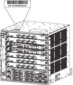
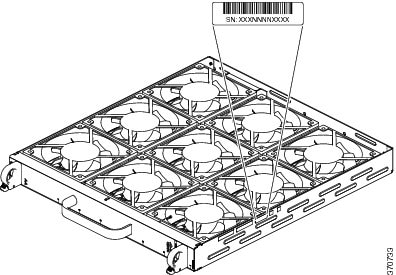
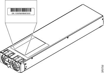
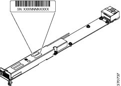
Finding Serial Numbers
If you contact Cisco Technical Assistance, you should know the serial number of the part you are having a problem with. You can also use the show version privileged EXEC command to see the serial number.
|
Item |
Serial Number Illustration |
|---|---|
|
Chassis |
|
|
Fan Tray |
|
|
Power Supply Module |
|
|
Power Supply Converter |
 Feedback