- Preface
- Using the Command-Line Interface
-
- Configuring Spanning Tree Protocol
- Configuring Multiple Spanning-Tree Protocol
- Configuring Optional Spanning-Tree Features
- Configuring EtherChannels
- Configuring Link-State Tracking
- Configuring Flex Links and the MAC Address-Table Move Update Feature
- Configuring UniDirectional Link Detection
- Configuring Resilient Ethernet Protocol
-
- Security Features Overview
- Preventing Unauthorized Access
- Controlling Switch Access with Passwords and Privilege Levels
- Configuring TACACS+
- Configuring RADIUS
- Configuring Kerberos
- Configuring Local Authentication and Authorization
- Configuring Secure Shell (SSH)
- Configuring Secure Socket Layer HTTP
- Configuring IPv4 ACLs
- Configuring IPv6 ACLs
- Configuring DHCP
- Configuring IP Source Guard
- Configuring Dynamic ARP Inspection
- Configuring IEEE 802.1x Port-Based Authentication
- Configuring Web-Based Authentication
- Configuring Port-Based Traffic Control
- Configuring IPv6 First Hop Security
- Configuring Cisco TrustSec
- Configuring FIPS
- Index
Consolidated Platform Configuration Guide, Cisco IOS XE 15.2(2)E (Catalyst 2960-XR Switch)
Bias-Free Language
The documentation set for this product strives to use bias-free language. For the purposes of this documentation set, bias-free is defined as language that does not imply discrimination based on age, disability, gender, racial identity, ethnic identity, sexual orientation, socioeconomic status, and intersectionality. Exceptions may be present in the documentation due to language that is hardcoded in the user interfaces of the product software, language used based on RFP documentation, or language that is used by a referenced third-party product. Learn more about how Cisco is using Inclusive Language.
- Updated:
- July 23, 2014
Chapter: Configuring Resilient Ethernet Protocol
Configuring Resilient Ethernet Protocol
Finding Feature Information
Your software release may not support all the features documented in this module. For the latest caveats and feature information, see Bug Search Tool and the release notes for your platform and software release. To find information about the features documented in this module, and to see a list of the releases in which each feature is supported, see the feature information table at the end of this module.
Use Cisco Feature Navigator to find information about platform support and Cisco software image support. To access Cisco Feature Navigator, go to http://www.cisco.com/go/cfn. An account on Cisco.com is not required.
REP Overview
Resilient Ethernet Protocol (REP) is a Cisco proprietary protocol that provides an alternative to Spanning Tree Protocol (STP) to control network loops, handle link failures, and improve convergence time. REP controls a group of ports connected in a segment, ensures that the segment does not create any bridging loops, and responds to link failures within the segment. REP provides a basis for constructing more complex networks and supports VLAN load balancing.
 Note | REP is supported on Catalyst switches running IP Base, IP Services, or IP Lite licenses. REP is not supported on the LAN Base license. |
A REP segment is a chain of ports connected to each other and configured with a segment ID. Each segment consists of standard (non-edge) segment ports and two user-configured edge ports. A router can have no more than two ports that belong to the same segment, and each segment port can have only one external neighbor. A segment can go through a shared medium, but on any link only two ports can belong to the same segment. REP is supported only on Trunk Ethernet Flow Point (EFP) interfaces.
The figure below shows an example of a segment consisting of six ports spread across four switches. Ports E1 and E2 are configured as edge ports. When all ports are operational (as in the segment on the left), a single port is blocked, shown by the diagonal line. When there is a failure in the network, the blocked port returns to the forwarding state to minimize network disruption.
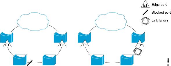
The segment shown in the figure above is an open segment; there is no connectivity between the two edge ports. The REP segment cannot cause a bridging loop, and you can safely connect the segment edges to any network. All hosts connected to routers inside the segment have two possible connections to the rest of the network through the edge ports, but only one connection is accessible at any time. If a failure occurs on any segment or on any port on a REP segment, REP unblocks all ports to ensure that connectivity is available through the other gateway.
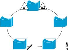
The segment shown in the figure below is a ring segment with both edge ports located on the same router. With this configuration, you can create a redundant connection between any two routers in the segment.
REP segments have the following characteristics:
-
If all ports in a segment are operational, one port (referred to as the alternate port) is in the blocked state for each VLAN. If VLAN load balancing is configured, two ports in the segment control the blocked state of VLANs.
-
If one or more ports in a segment is not operational, and cause a link failure, all ports forward traffic on all VLANs to ensure connectivity.
-
In case of a link failure, alternate ports are unblocked as quickly as possible. When the failed link is up, a logically blocked port per VLAN is selected with minimal disruption to the network.
You can construct almost any type of network based on REP segments. REP also supports VLAN load balancing, which is controlled by the primary edge port occurring at any port in the segment.
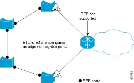
In access ring topologies, the neighboring switch might not support REP as shown in the figure below. In this case, you can configure the non-REP facing ports (E1 and E2) as edge no-neighbor ports. These ports inherit all properties of edge ports, and you can configure them the same as any edge port, including configuring them to send STP or REP topology change notices to the aggregation switch. In this case, the STP topology change notice (TCN) that is sent is a multiple spanning-tree (MST) STP message.
REP has these limitations:
-
You must configure each segment port; an incorrect configuration can cause forwarding loops in the networks.
-
REP can manage only a single failed port within the segment; multiple port failures within the REP segment cause loss of network connectivity.
-
You should configure REP only in networks with redundancy. Configuring REP in a network without redundancy causes loss of connectivity.
Link Integrity
REP does not use an end-to-end polling function between edge ports to verify link integrity. It implements local link failure detection. The REP Link Status Layer (LSL) detects its REP-aware neighbor and establishes connectivity within the segment. All VLANs are blocked on an interface until it detects the neighbor. After the neighbor is identified, REP determines which neighbor port should become the alternate port and which ports should forward traffic.
Each port in a segment has a unique port ID. The port ID format is similar to that used by the spanning tree algorithm: a port number (unique on the bridge), associated to a MAC address (unique in the network). When a segment port is coming up, its LSL starts sending packets that include the segment ID and the port ID. The port is declared as operational after it performs a three-way handshake with a neighbor in the same segment.
A segment port does not become operational if:
-
No neighbor has the same segment ID.
-
More than one neighbor has the same segment ID.
-
The neighbor does not acknowledge the local port as a peer.
Each port creates an adjacency with its immediate neighbor. Once the neighbor adjacencies are created, the ports negotiate to determine one blocked port for the segment, the alternate port. All other ports become unblocked. By default, REP packets are sent to a BPDU class MAC address. The packets can also be sent to the Cisco multicast address, which is used only to send blocked port advertisement (BPA) messages when there is a failure in the segment. The packets are dropped by devices not running REP.
Fast Convergence
REP runs on a physical link basis and not on a per-VLAN basis. Only one hello message is required for all VLANs, and it reduces the load on the protocol. We recommend that you create VLANs consistently on all switches in a given segment and configure the same allowed VLANs on the REP trunk ports. To avoid the delay introduced by relaying messages in software, REP also allows some packets to be flooded to a regular multicast address. These messages operate at the hardware flood layer (HFL) and are flooded to the whole network, not just the REP segment. Switches that do not belong to the segment treat them as data traffic. You can control flooding of these messages by configuring a dedicated administrative VLAN for the whole domain.
The estimated convergence recovery time on fiber interfaces is between 50 ms and 200 ms for the local segment with 200 VLANs configured. Convergence for VLAN load balancing is 300 ms or less.
VLAN Load Balancing
ne edge port in the REP segment acts as the primary edge port; the other as the secondary edge port. It is the primary edge port that always participates in VLAN load balancing in the segment. REP VLAN balancing is achieved by blocking some VLANs at a configured alternate port and all other VLANs at the primary edge port. When you configure VLAN load balancing, you can specify the alternate port in one of three ways:
-
By entering the port ID of the interface. To identify the port ID of a port in the segment, enter the show interface rep detail interface configuration command for the port.
-
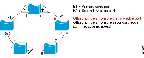
By entering the neighbor offset number of a port in the segment, which identifies the downstream neighbor port of an edge port. The neighbor offset number range is –256 to +256; a value of 0 is invalid. The primary edge port has an offset number of 1; positive numbers above 1 identify downstream neighbors of the primary edge port. Negative numbers indicate the secondary edge port (offset number -1) and its downstream neighbors.
Note | You configure offset numbers on the primary edge port by identifying a port’s downstream position from the primary (or secondary) edge port. You would never enter an offset value of 1 because that is the offset number of the primary edge port itself. |
The figure below shows neighbor offset numbers for a segment where E1 is the primary edge port and E2 is the secondary edge port. The red numbers inside the ring are numbers offset from the primary edge port; the black numbers outside of the ring show the offset numbers from the secondary edge port. Note that you can identify all ports (except the primary edge port) by either a positive offset number (downstream position from the primary edge port) or a negative offset number (downstream position from the secondary edge port). If E2 became the primary edge port, its offset number would then be 1 and E1 would be -1.
-
By entering the preferred keyword to select the port that you previously configured as the preferred alternate port with the rep segment segment-id preferred interface configuration command.
When the REP segment is complete, all VLANs are blocked. When you configure VLAN load balancing,you must also configure triggers in one of two ways:
-
Manually trigger VLAN load balancing at any time by entering the rep preempt segment segment-id privileged EXEC command on the switch that has the primary edge port.
-
Configure a preempt delay time by entering the rep preempt delay seconds interface configuration command. After a link failure and recovery, VLAN load balancing begins after the configured preemption time period elapses. Note that the delay timer restarts if another port fails before the time has elapsed.
Note | When VLAN load balancing is configured, it does not start working until triggered by either manual intervention or a link failure and recovery. |
When VLAN load balancing is triggered, the primary edge port sends out a message to alert all interfaces in the segment about the preemption. When the secondary port receives the message, it is reflected into the network to notify the alternate port to block the set of VLANs specified in the message and to notify the primary edge port to block the remaining VLANs.
You can also configure a particular port in the segment to block all VLANs. Only the primary edge port initiates VLAN load balancing, which is not possible if the segment is not terminated by an edge port on each end. The primary edge port determines the local VLAN load balancing configuration.
Reconfigure the primary edge port to reconfigure load balancing. When you change the load balancing configuration, the primary edge port again waits for the rep preempt segment command or for the configured preempt delay period after a port failure and recovery before executing the new configuration. If you change an edge port to a regular segment port, the existing VLAN load balancing status does not change. Configuring a new edge port might cause a new topology configuration.
Spanning Tree Interaction
REP does not interact with STP or with the Flex Link feature, but can coexist with both. A port that belongs to a segment is removed from spanning tree control and STP BPDUs are not accepted or sent from segment ports. Therefore, STP cannot run on a segment.
To migrate from an STP ring configuration to REP segment configuration, begin by configuring a single port in the ring as part of the segment and continue by configuring contiguous ports to minimize the number of segments. Each segment always contains a blocked port, so multiple segments means multiple blocked ports and a potential loss of connectivity. When the segment has been configured in both directions up to the location of the edge ports, you then configure the edge ports.
REP Ports
REP segments consists of Failed, Open, or Alternate ports.
-
A port configured as a regular segment port starts as a failed port.
-
After the neighbor adjacencies are determined, the port transitions to alternate port state, blocking all VLANs on the interface. Blocked port negotiations occur and when the segment settles, one blocked port remains in the alternate role and all other ports become open ports.
-
When a failure occurs in a link, all ports move to the failed state. When the alternate port receives the failure notification, it changes to the open state, forwarding all VLANs.
A regular segment port converted to an edge port, or an edge port converted to a regular segment port, does not always result in a topology change. If you convert an edge port into a regular segment port, VLAN load balancing is not implemented unless it has been configured. For VLAN load balancing, you must configure two edge ports in the segment.
A segment port that is reconfigured as a spanning tree port restarts according the spanning tree configuration. By default, this is a designated blocking port. If PortFast is configured or if STP is disabled, the port goes into the forwarding state.
How to Configure REP
A segment is a collection of ports connected one to the other in a chain and configured with a segment ID. To configure REP segments, you configure the REP administrative VLAN (or use the default VLAN 1) and then add the ports to the segment using interface configuration mode. You should configure two edge ports in the segment, with one of them the primary edge port and the other by default the secondary edge port. A segment has only one primary edge port. If you configure two ports in a segment as the primary edge port, for example, ports on different switches, the REP selects one of them to serve as the segment primary edge port. You can also optionally configure where to send segment topology change notices (STCNs) and VLAN load balancing.
- Default REP Configuration
- REP Configuration Guidelines
- Configuring the REP Administrative VLAN
- Configuring REP Interfaces
- Setting Manual Preemption for VLAN Load Balancing
- Configuring SNMP Traps for REP
Default REP Configuration
REP is disabled on all interfaces. When enabled, the interface is a regular segment port unless it is configured as an edge port.
When REP is enabled, the sending of segment topology change notices (STCNs) is disabled, all VLANs are blocked, and the administrative VLAN is VLAN 1.
When VLAN load balancing is enabled, the default is manual preemption with the delay timer disabled. If VLAN load balancing is not configured, the default after manual preemption is to block all VLANs at the primary edge port.
REP Configuration Guidelines
Follow these guidelines when configuring REP:
-
We recommend that you begin by configuring one port and then configure contiguous ports to minimize the number of segments and the number of blocked ports.
-
If more than two ports in a segment fail when no external neighbors are configured, one port goes into a forwarding state for the data path to help maintain connectivity during configuration. In the show rep interface command output, the Port Role for this port shows as “Fail Logical Open”; the Port Role for the other failed port shows as “Fail No Ext Neighbor”. When the external neighbors for the failed ports are configured, the ports go through the alternate port state transitions and eventually go to an open state or remain as the alternate port, based on the alternate port selection mechanism.
-
REP ports must be Layer 2 IEEE 802.1Q or Trunk ports.
-
We recommend that you configure all trunk ports in the segment with the same set of allowed VLANs.
-
Be careful when configuring REP through a Telnet connection. Because REP blocks all VLANs until another REP interface sends a message to unblock it. You might lose connectivity to the router if you enable REP in a Telnet session that accesses the router through the same interface.
-
You cannot run REP and STP or REP and Flex Links on the same segment or interface.
-
If you connect an STP network to a REP segment, be sure that the connection is at the segment edge. An STP connection that is not at the edge could cause a bridging loop because STP does not run on REP segments. All STP BPDUs are dropped at REP interfaces.
-
You must configure all trunk ports in the segment with the same set of allowed VLANs, or a misconfiguration occurs.
-
If REP is enabled on two ports on a switch, both ports must be either regular segment ports or edge ports. REP ports follow these rules: -
There is no limit to the number of REP ports on a switch; however, only two ports on a switch can belong to the same REP segment.
-
If only one port on a switch is configured in a segment, the port should be an edge port.
-
If two ports on a switch belong to the same segment, they must be both edge ports, both regular segment ports, or one regular port and one edge no-neighbor port. An edge port and regular segment port on a switch cannot belong to the same segment.
-
If two ports on a switch belong to the same segment and one is configured as an edge port and one as a regular segment port (a misconfiguration), the edge port is treated as a regular segment port.
-
-
REP interfaces come up in a blocked state and remain in a blocked state until they are safe to be unblocked. You need to be aware of this status to avoid sudden connection losses.
-
REP sends all LSL PDUs in untagged frames on the native VLAN. The BPA message sent to the Cisco multicast address is sent on the administration VLAN, which is VLAN 1 by default.
-
You can configure how long a REP interface remains up without receiving a hello from a neighbor. You can use therep lsl-age-timer value interface configuration command to set the time from 120 ms to 10000 ms. The LSL hello timer is then set to the age-timer value divided by 3. In normal operation, three LSL hellos are sent before the age timer on the peer switch expires and checks forhello messages.
-
REP ports cannot be configured as one of the following port types: -
REP is supported on EtherChannels, but not on an individual port that belongs to an EtherChannel.
-
There can be a maximum of 64 REP segments per switch.
Configuring the REP Administrative VLAN
To avoid the delay introduced by relaying messages in the software for link-failure or by VLAN-blocking notifications during load balancing, the REP floods packets to a regular multicast address at the hardware flood layer (HFL). These messages are flooded to the whole network, not just the REP segment. You can control flooding of these messages by configuring an administrative VLAN for the whole domain.
Follow these guidelines when configuring the REP administrative VLAN:
-
If you do not configure an administrative VLAN, the default is VLAN 1.
-
There can be only one administrative VLAN on a switch and on a segment. However, this is not enforced by software.
-
The administrative VLAN cannot be the RSPAN VLAN.
To configure the REP administrative VLAN, follow these steps, beginning in privileged EXEC mode:
1.
configure
terminal
2.
rep
admin
vlan
vlan-id
3.
end
DETAILED STEPS
Configuring REP Interfaces
For the REP operation, you must enable REP on each segment interface and identify the segment ID. This task is required and must be done before other REP configurations. You must also configure a primary and secondary edge port on each segment. All other steps are optional.
Follow these steps to enable and configure REP on an interface:
1.
enable
2.
configure
terminal
3.
interface
interface-id
4.
switchport mode trunk
5.
rep
segment
segment-id
[edge
[no-neighbor]
[ [primary]]
[preferred]
6.
rep
stcn
{interface
interface id
|
segment
id-list |
stp}
7.
rep
block
port
{id
port-id
|
neighbor-offset |
preferred}
vlan {vlan-list |
all}
8.
rep
preempt
delay
seconds
9.
rep lsl-age-timer
value
10.
end
11.
show
interface
[interface-id]
rep [detail]
12.
copy
running-config
startup-config
DETAILED STEPS
| Command or Action | Purpose | |||||||
|---|---|---|---|---|---|---|---|---|
| Step 1 |
enable
Example:
Switch> enable
|
Enables privileged EXEC mode. Enter your password if prompted. | ||||||
| Step 2 |
configure
terminal
|
Enters global configuration mode. | ||||||
| Step 3 |
interface
interface-id
|
Specifies the interface, and enter interface configuration mode. The interface can be a physical Layer 2 interface or a port channel (logical interface). The port-channel range is 1 to 48. | ||||||
| Step 4 | switchport mode trunk
|
Configures the interface as a Layer 2 trunk port. | ||||||
| Step 5 |
rep
segment
segment-id
[edge
[no-neighbor]
[ [primary]]
[preferred]
|
Enables REP on the interface and identifies a segment number. The segment ID range is from 1 to 1024. These optional keywords are available:
| ||||||
| Step 6 |
rep
stcn
{interface
interface id
|
segment
id-list |
stp}
|
| ||||||
| Step 7 |
rep
block
port
{id
port-id
|
neighbor-offset |
preferred}
vlan {vlan-list |
all}
|
(Optional) Configures VLAN load balancing on the primary edge port, identifies the REP alternate port in one of three ways, and configures the VLANs to be blocked on the alternate port.
| ||||||
| Step 8 |
rep
preempt
delay
seconds
|
(Optional) Configures a preempt time delay.
| ||||||
| Step 9 | rep lsl-age-timer
value
|
(Optional) Configures a time (in milliseconds) for which the REP interface remains up without receiving a hello from a neighbor. The range is from 120 to 10000 ms in 40-ms increments. The default is 5000 ms (5 seconds).
| ||||||
| Step 10 |
end
|
Returns to privileged EXEC mode. | ||||||
| Step 11 |
show
interface
[interface-id]
rep [detail]
|
(Optional) Displays the REP interface configuration. | ||||||
| Step 12 |
copy
running-config
startup-config
|
(Optional) Saves your entries in the router startup configuration file. |
Setting Manual Preemption for VLAN Load Balancing
If you do not enter therep preempt delayseconds rep preempt delay seconds interface configuration command on the primary edge port to configure a preemption time delay, the default is to manually trigger VLAN load balancing on the segment. Be sure that all other segment configuration has been completed before manually preempting VLAN load balancing. When you enter the rep preempt delaysegment-id command, a confirmation message appears before the command is executed because preemption can cause network disruption.
1.
rep preempt segment
segment-id
2.
show rep topology
segment-id
DETAILED STEPS
| Command or Action | Purpose |
|---|
Configuring SNMP Traps for REP
You can configure the router to send REP-specific traps to notify the Simple Network Management Protocol (SNMP) server of link operational status changes and any port role changes.
1.
configure
terminal
2.
snmp
mib
rep
trap-rate
value
3.
end
4.
show
running-config
5.
copy
running-config
startup-config
DETAILED STEPS
Monitoring REP
1.
show interface
[interface-id]
rep
[detail]
2.
show rep topology
[segment
segment-_id]
[archive
]
[detail]
DETAILED STEPS
Configuring Examples for Configuring REP
Configuring the REP Administrative VLAN: Examples
This example shows how to configure the administrative VLAN as VLAN 100 and verify the configuration by entering the show interface rep detailshow interface rep detail command on one of the REP interfaces:
Switch# configure terminal
Switch (conf)# rep admin vlan 100
Switch (conf-if)# end
Switch# show interface gigabitethernet1/1 rep details
GigabitEthernet1/1 REP enabled
Segment-id: 2 (Edge)
PortID: 00010019E7144680
Preferred flag: No
Operational Link Status: TWO_WAY
Current Key: 0002001121A2D5800E4D
Port Role: Open
Blocked Vlan: <empty>
Admin-vlan: 100
Preempt Delay Timer: disabled
LSL Ageout Timer: 5000 ms
Configured Load-balancing Block Port: none
Configured Load-balancing Block VLAN: none
STCN Propagate to: none
LSL PDU rx: 3322, tx: 1722
HFL PDU rx: 32, tx: 5
BPA TLV rx: 16849, tx: 508
BPA (STCN, LSL) TLV rx: 0, tx: 0
BPA (STCN, HFL) TLV rx: 0, tx: 0
EPA-ELECTION TLV rx: 118, tx: 118
EPA-COMMAND TLV rx: 0, tx: 0
EPA-INFO TLV rx: 4214, tx: 4190
Configuring REP Interfaces: Examples
This example shows how to configure an interface as the primary edge port for segment 1, to send STCNs to segments 2 through 5, and to configure the alternate port as the port with port ID 0009001818D68700 to block all VLANs after a preemption delay of 60 seconds after a segment port failure and recovery. The interface is configured to remain up for 6000 milliseconds without receiving a hello from a neighbor.
Switch# configure terminal
Switch (conf)# interface gigabitethernet1/1
Switch (conf-if)# rep segment 1 edge primary
Switch (conf-if)# rep stcn segment 2-5
Switch (conf-if)# rep block port 0009001818D68700 vlan all
Switch (conf-if)# rep preempt delay 60
Switch (conf-if)# rep lsl-age-timer 6000
Switch (conf-if)# end
This example shows how to configure the same configuration when the interface has no external REP neighbor:
Switch# configure terminal
Switch (conf)# interface gigabitethernet1/1
Switch (conf-if)# rep segment 1 edge no-neighbor primary
Switch (conf-if)# rep stcn segment 2-5
Switch (conf-if)# rep block port 0009001818D68700 vlan all
Switch (conf-if)# rep preempt delay 60
Switch (conf-if)# rep lsl-age-timer 6000
Switch (conf-if)# end
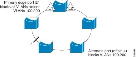
This example shows how to configure the VLAN blocking configuration shown in the figure below. The alternate port is the neighbor with neighbor offset number 4. After manual preemption, VLANs 100 to 200 are blocked at this port, and all other VLANs are blocked at the primary edge port E1 (Gigabit Ethernet port 1/1).
Switch# configure terminal
Switch (conf)# interface gigabitethernet1/1
Switch (conf-if)# rep segment 1 edge primary
Switch (conf-if)# rep block port 4 vlan 100-200
Switch (conf-if)# end
 Feedback