Configuring QoS

Finding Feature Information

Your software release may not support all the features documented in this module. For the latest feature information and caveats, see the release notes for your platform and software release.

Use Cisco Feature Navigator to find information about platform support and Cisco software image support. To access Cisco Feature Navigator, go to http://www.cisco.com/go/cfn. An account on Cisco.com is not required.

Prerequisites for QoS

Before configuring standard QoS, you must have a thorough understanding of these items:

  • The types of applications used and the traffic patterns on your network.

  • Traffic characteristics and needs of your network. For example, is the traffic on your network bursty? Do you need to reserve bandwidth for voice and video streams?

  • Bandwidth requirements and speed of the network.

  • Location of congestion points in the network.

QoS ACL Guidelines

Follow these guidelines when configuring QoS with access control lists (ACLs):

  • It is not possible to match IP fragments against configured IP extended ACLs to enforce QoS. IP fragments are sent as best-effort. IP fragments are denoted by fields in the IP header.

  • Only one ACL per class map and only one match class-map configuration command per class map are supported. The ACL can have multiple ACEs, which match fields against the contents of the packet.

Policing Guidelines

  • Only one policer is applied to a packet on an ingress port. Only the average rate and committed burst parameters are configurable.

  • On a port configured for QoS, all traffic received through the port is classified, policed, and marked according to the policy map attached to the port. On a trunk port configured for QoS, traffic in all VLANs received through the port is classified, policed, and marked according to the policy map attached to the port.

  • If you have EtherChannel ports configured on your switch, you must configure QoS classification, policing, mapping, and queueing on the individual physical ports that comprise the EtherChannel. You must decide whether the QoS configuration should match on all ports in the EtherChannel.

  • If you need to modify a policy map of an existing QoS policy, first remove the policy map from all interfaces, and then modify or copy the policy map. After you finish the modification, apply the modified policy map to the interfaces. If you do not first remove the policy map from all interfaces, high CPU usage can occur, which, in turn, can cause the console to pause for a very long time.

General QoS Guidelines

These are the general QoS guidelines:

  • You configure QoS only on physical ports; there is no support for it at the VLAN level and EtherChannel ports.

  • Control traffic (such as spanning-tree bridge protocol data units [BPDUs] and routing update packets) received by the switch are subject to all ingress QoS processing.

  • You are likely to lose data when you change queue settings; therefore, try to make changes when traffic is at a minimum.

Restrictions for QoS

The following are the restrictions for QoS:

  • Ingress queueing and aggregate policy are not supported.

  • Only 32 class-maps are supported per ASIC.

  • Ternary content-addressable memory (TCAM) sharing of policy-map (policer/marking) across ports is not supported. Because of this, the number of interfaces on which auto-QoS/QoS policy-map can be applied is limited.

  • The same TCAM region must be used for both security Access control lists (ACLs) and ACLs used via policy map.

  • Policy-maps with the match ip dscp command matches both IPv4 and IPv6 addresses, which limits the scale number to 16 class-maps. One TCAM entry is created for IPv4 and one TCAM entry for IPv6.

  • Per ASIC, 8 TCP port comparators and 8 UDP port comparators are supported, and each gt (greater than)/lt (less than)/neq (not equal) operator uses 1 port comparator, and each range operator uses 2 port comparators. A policy-map with this combination affects the TCAM scale and number of interfaces to which the policy-map can be attached.

  • The following restrictions apply to IPv4 ACL network interfaces:

    • When controlling access to an interface, you can use a named or numbered ACL.

    • If you apply an ACL to a Layer 3 interface, and routing is not enabled on the switch, the ACL only filters packets that are intended for the CPU, such as SNMP, Telnet, or web traffic.

    • You do not have to enable routing to apply ACLs on Layer 2 interfaces.

  • Deny ACLs are not supported on QoS policy-maps.

  • Policed action transmit is not supported; only exceed action drop is supported.

  • You can configure QoS only on physical ports. VLAN-based QoS is not supported. You configure the QoS settings, such as classification, queueing, and scheduling, and apply the policy map to a port. When configuring QoS on a physical port, you apply a nonhierarchical policy map to a port.

Information About QoS

QoS Implementation

Typically, networks operate on a best-effort delivery basis, which means that all traffic has equal priority and an equal chance of being delivered in a timely manner. When congestion occurs, all traffic has an equal chance of being dropped.

When you configure the QoS feature, you can select specific network traffic, prioritize it according to its relative importance, and use congestion-management and congestion-avoidance techniques to provide preferential treatment. Implementing QoS in your network makes network performance more predictable and bandwidth utilization more effective.

The QoS implementation is based on the Differentiated Services (Diff-Serv) architecture, a standard from the Internet Engineering Task Force (IETF). This architecture specifies that each packet is classified upon entry into the network.

Figure 1. QoS Classification Layers in Frames and Packets. The special bits in the Layer 2 frame or a Layer 3 packet are shown in the following figure:

Layer 2 Frame Prioritization Bits

Layer 2 Inter-Switch Link (ISL) frame headers have a 1-byte User field that carries an IEEE 802.1p class of service (CoS) value in the three least-significant bits. On ports configured as Layer 2 ISL trunks, all traffic is in ISL frames.

Layer 2 802.1Q frame headers have a 2-byte Tag Control Information field that carries the CoS value in the three most-significant bits, which are called the User Priority bits. On ports configured as Layer 2 802.1Q trunks, all traffic is in 802.1Q frames except for traffic in the native VLAN.

Other frame types cannot carry Layer 2 CoS values.

Layer 2 CoS values range from 0 for low priority to 7 for high priority.

Layer 3 Packet Prioritization Bits

Layer 3 IP packets can carry ranging from 0 to 63.

End-to-End QoS Solution Using Classification

All switches and routers that access the Internet rely on the class information to provide the same forwarding treatment to packets with the same class information and different treatment to packets with different class information. The class information in the packet can be assigned by end hosts or by switches or routers along the way, based on a configured policy, detailed examination of the packet, or both. Detailed examination of the packet is expected to occur closer to the edge of the network, so that the core switches and routers are not overloaded with this task.

Switches and routers along the path can use the class information to limit the amount of resources allocated per traffic class. The behavior of an individual device when handling traffic in the Diff-Serv architecture is called per-hop behavior. If all devices along a path provide a consistent per-hop behavior, you can construct an end-to-end QoS solution.

Implementing QoS in your network can be a simple task or complex task and depends on the QoS features offered by your internetworking devices, the traffic types and patterns in your network, and the granularity of control that you need over incoming and outgoing traffic.

QoS Basic Model

To implement QoS, the switch must distinguish packets or flows from one another (classify), assign a label to indicate the given quality of service as the packets move through the switch, make the packets comply with the configured resource usage limits (police and mark), and provide different treatment (queue and schedule) in all situations where resource contention exists. The switch also needs to ensure that traffic sent from it meets a specific traffic profile (shape).

Figure 2. QoS Basic Wired Model

Actions at Ingress Port

Actions at the ingress port include classifying traffic, policing, and marking:

  • Classifying a distinct path for a packet by associating it with a QoS label. The switch maps the CoS or DSCP in the packet to a QoS label to distinguish one kind of traffic from another. The QoS label that is generated identifies all future QoS actions to be performed on this packet.

  • Policing determines whether a packet is in or out of profile by comparing the rate of the incoming traffic to the configured policer. The policer limits the bandwidth consumed by a flow of traffic. The result is passed to the marker.

  • Marking evaluates the policer and configuration information for the action to be taken when a packet is out of profile and determines what to do with the packet (pass through a packet without modification, marking down the QoS label in the packet, or dropping the packet).


Note

Queueing and scheduling are only supported at egress and not at ingress on the switch.


Actions at Egress Port

Actions at the egress port include queueing and scheduling:

  • Queueing evaluates the QoS packet label and the corresponding CoS value before selecting which of the four egress queues to use. Because congestion can occur when multiple ingress ports simultaneously send data to an egress port, WTD differentiates traffic classes and subjects the packets to different thresholds based on the QoS label. If the threshold is exceeded, the packet is dropped.

  • Scheduling services the four egress queues based on their configured SRR shared or shaped weights. One of the queues (queue 1) can be the priority queue, which is serviced until empty before the other queues are serviced.

Classification Overview

Classification is the process of distinguishing one kind of traffic from another by examining the fields in the packet. Classification is enabled only if QoS is globally enabled on the switch. By default, QoS is globally disabled, so no classification occurs.

During classification, the switch performs a lookup and assigns a QoS label to the packet. The QoS label identifies all QoS actions to be performed on the packet and from which queue the packet is sent.

The QoS label is based on the DSCP or the CoS value in the packet and decides the queuing and scheduling actions to perform on the packet. The label is mapped according to the trust setting and the packet type as shown in the Classification Flowchart.

You specify which fields in the frame or packet that you want to use to classify incoming traffic.

Non-IP Traffic Classification

The following table describes the non-IP traffic classification options for your QoS configuration.

Table 1. Non- IP Traffic Classifications

Non-IP Traffic Classification

Description

Trust the CoS value

Trust the CoS value in the incoming frame (configure the port to trust CoS), and then use the configurable CoS-to-DSCP map to generate a DSCP value for the packet.

Layer 2 ISL frame headers carry the CoS value in the 3 least-significant bits of the 1-byte User field.

Layer 2 802.1Q frame headers carry the CoS value in the 3 most-significant bits of the Tag Control Information field. CoS values range from 0 for low priority to 7 for high priority.

Trust the DSCP value

Trust the DSCP value in the incoming frame. These configurations are meaningless for non-IP traffic. If you configure a port with either of these options and non-IP traffic is received, the switch assigns a CoS value and generates an internal DSCP value from the CoS-to-DSCP map. The switch uses the internal DSCP value to generate a CoS value representing the priority of the traffic.

Perform classification based on configured Layer 2 MAC ACL

Perform the classification based on a configured Layer 2 MAC access control list (ACL), which can examine the MAC source address, the MAC destination address, and other fields. If no ACL is configured, the packet is assigned 0 as the DSCP and CoS values, which means best-effort traffic. Otherwise, the policy-map action specifies a DSCP or CoS value to assign to the incoming frame.

After classification, the packet is sent to the policing and marking stages.

IP Traffic Classification

The following table describes the IP traffic classification options for your QoS configuration.

Table 2. IP Traffic Classifications

IP Traffic Classification

Description

Trust the DSCP value

Trust the DSCP value in the incoming packet (configure the port to trust DSCP), and assign the same DSCP value to the packet. The IETF defines the 6 most-significant bits of the 1-byte ToS field as the DSCP. The priority represented by a particular DSCP value is configurable. DSCP values range from 0 to 63.

You can also classify IP traffic based on IPv6 DSCP.

For ports that are on the boundary between two QoS administrative domains, you can modify the DSCP to another value by using the configurable DSCP-to-DSCP-mutation map.

Trust the CoS value

Trust the CoS value (if present) in the incoming packet, and generate a DSCP value for the packet by using the CoS-to-DSCP map. If the CoS value is not present, use the default port CoS value.

IP standard or an extended ACL

Perform the classification based on a configured IP standard or an extended ACL, which examines various fields in the IP header. If no ACL is configured, the packet is assigned 0 as the DSCP and CoS values, which means best-effort traffic. Otherwise, the policy-map action specifies a DSCP or CoS value to assign to the incoming frame.

Override configured CoS

Override the configured CoS of incoming packets, and apply the default port CoS value to them. For IPv6 packets, the DSCP value is rewritten by using the CoS-to-DSCP map and by using the default CoS of the port. You can do this for both IPv4 and IPv6 traffic.

After classification, the packet is sent to the policing and marking stages.

Classification Flowchart
Figure 3. Classification Flowchart
Access Control Lists

You can use IP standard, IP extended, or Layer 2 MAC ACLs to define a group of packets with the same characteristics (class). You can also classify IP traffic based on IPv6 ACLs.

In the QoS context, the permit and deny actions in the access control entries (ACEs) have different meanings from security ACLs:

  • If a match with a permit action is encountered (first-match principle), the specified QoS-related action is taken.

  • If a match with a deny action is encountered, the ACL being processed is skipped, and the next ACL is processed.


    Note

    Deny action is supported in Cisco IOS Release 3.7.4E and later releases.


  • If no match with a permit action is encountered and all the ACEs have been examined, no QoS processing occurs on the packet, and the switch offers best-effort service to the packet.

  • If multiple ACLs are configured on a port, the lookup stops after the packet matches the first ACL with a permit action, and QoS processing begins.


    Note

    When creating an access list, note that by default the end of the access list contains an implicit deny statement for everything if it did not find a match before reaching the end.


After a traffic class has been defined with the ACL, you can attach a policy to it. A policy might contain multiple classes with actions specified for each one of them. A policy might include commands to classify the class as a particular aggregate (for example, assign a DSCP) or rate-limit the class. This policy is then attached to a particular port on which it becomes effective.

You implement IP ACLs to classify IP traffic by using the access-list global configuration command; you implement Layer 2 MAC ACLs to classify non-IP traffic by using the mac access-list extended global configuration command.

Classification Based on Class Maps and Policy Maps

A class map is a mechanism that you use to name a specific traffic flow (or class) and to isolate it from all other traffic. The class map defines the criteria used to match against a specific traffic flow to further classify it. The criteria can include matching the access group defined by the ACL or matching a specific list of DSCP values. If you have more than one type of traffic that you want to classify, you can create another class map and use a different name. After a packet is matched against the class-map criteria, you further classify it through the use of a policy map.

A policy map specifies which traffic class to act on. Actions can include trusting the CoS or DSCP values in the traffic class; setting a specific DSCP value in the traffic class; or specifying the traffic bandwidth limitations and the action to take when the traffic is out of profile. Before a policy map can be effective, you must attach it to a port.

You create a class map by using the class-map global configuration command or the class policy-map configuration command. You should use the class-map command when the map is shared among many ports. When you enter the class-map command, the switch enters the class-map configuration mode. In this mode, you define the match criterion for the traffic by using the match class-map configuration command.

You can configure a default class by using the class class-default policy-map configuration command. Unclassified traffic (traffic specified in the other traffic classes configured on the policy-map) is treated as default traffic.

You create and name a policy map by using the policy-map global configuration command. When you enter this command, the switch enters the policy-map configuration mode. In this mode, you specify the actions to take on a specific traffic class by using the class or set policy-map configuration and policy-map class configuration commands.

The policy map can contain the police policy-map class configuration commands, which define the policer, the bandwidth limitations of the traffic, and the action to take if the limits are exceeded.

To enable the policy map, you attach it to a port by using the service-policy interface configuration command.

Policing and Marking Overview

After a packet is classified and has a DSCP-based or CoS-based QoS label assigned to it, the policing and marking process can begin.

Policing involves creating a policer that specifies the bandwidth limits for the traffic. Packets that exceed the limits are out of profile or nonconforming. Each policer decides on a packet-by-packet basis whether the packet is in or out of profile and specifies the actions on the packet. These actions, carried out by the marker, include passing through the packet without modification, dropping the packet, or modifying (marking down) the assigned DSCP of the packet and allowing the packet to pass through. The configurable policed-DSCP map provides the packet with a new DSCP-based QoS label. Marked-down packets use the same queues as the original QoS label to prevent packets in a flow from getting out of order.


Note

All traffic, regardless of whether it is bridged or routed, is subjected to a policer, if one is configured. As a result, bridged packets might be dropped or might have their DSCP or CoS fields modified when they are policed and marked.


You can configure policing on a physical port. After you configure the policy map and policing actions, attach the policy to a port by using the service-policy interface configuration command.

Physical Port Policing

In policy maps on physical ports, you can create individual policers. QoS applies the bandwidth limits specified in the policer separately to each matched traffic class. You configure this type of policer within a policy map by using the police policy-map class configuration command.

Policing uses a token-bucket algorithm. As each frame is received by the switch, a token is added to the bucket. The bucket has a hole in it and leaks at a rate that you specify as the average traffic rate in bits per second. Each time a token is added to the bucket, the switch verifies that there is enough room in the bucket. If there is not enough room, the packet is marked as nonconforming, and the specified policer action is taken (dropped or marked down).

How quickly the bucket fills is a function of the bucket depth (burst-byte), the rate at which the tokens are removed (rate-bps), and the duration of the burst above the average rate. The size of the bucket imposes an upper limit on the burst length and limits the number of frames that can be transmitted back-to-back. If the burst is short, the bucket does not overflow, and no action is taken against the traffic flow. However, if a burst is long and at a higher rate, the bucket overflows, and the policing actions are taken against the frames in that burst.

You configure the bucket depth (the maximum burst that is tolerated before the bucket overflows) by using the burst-byte option of the police policy-map class configuration command. You configure how fast (the average rate) that the tokens are removed from the bucket by using the rate-bps option of the police policy-map class configuration command.

Figure 4. Policing and Marking Flowchart on Physical Ports.

Queueing and Scheduling Overview

The switch has queues at specific points to help prevent congestion.

Figure 5. Egress Queue Location on Switch

Note

The switch supports 4 egress queues by default and there is an option to enable a total of 8 egress queues. The 8 egress queue configuration is only supported on a standalone switch.

The Catalyst 2960-L switches support Scheduled Round Robin (SRR). They do not support Weighted Round Robin (WRR). Currently, you can configure SRR with wrr commands instead of srr commands. From Cisco IOS Release 15.2(5)E2 and later, the wrr commands will be replaced with the srr commands on the switch.


Weighted Tail Drop

Egress queues use an enhanced version of the tail-drop congestion-avoidance mechanism called weighted tail drop (WTD). WTD is implemented on queues to manage the queue lengths and to provide drop precedences for different traffic classifications.

As a frame is enqueued to a particular queue, WTD uses the frame’s assigned QoS label to subject it to different thresholds. If the threshold is exceeded for that QoS label (the space available in the destination queue is less than the size of the frame), the switch drops the frame.

Each queue has three threshold values. The QoS label determines which of the three threshold values is subjected to the frame. Of the three thresholds, two are configurable (explicit) and one is not (implicit).

Figure 6. WTD and Queue Operation. The following figure shows an example of WTD operating on a queue whose size is 1000 frames. Three drop percentages are configured: 40 percent (400 frames), 60 percent (600 frames), and 100 percent (1000 frames). These percentages indicate that up to 400 frames can be queued at the 40-percent threshold, up to 600 frames at the 60-percent threshold, and up to 1000 frames at the 100-percent threshold.

In the example, CoS values 6 and 7 have a greater importance than the other CoS values, and they are assigned to the 100-percent drop threshold (queue-full state). CoS values 4 and 5 are assigned to the 60-percent threshold, and CoS values 0 to 3 are assigned to the 40-percent threshold.

Suppose the queue is already filled with 600 frames, and a new frame arrives. It contains CoS values 4 and 5 and is subjected to the 60-percent threshold. If this frame is added to the queue, the threshold will be exceeded, so the switch drops it.

SRR Shaping and Sharing

You can configure SRR on egress queues for sharing or for shaping.

In shaped mode, the egress queues are guaranteed a percentage of the bandwidth, and they are rate-limited to that amount. Shaped traffic does not use more than the allocated bandwidth even if the link is idle. Shaping provides a more even flow of traffic over time and reduces the peaks and valleys of bursty traffic. With shaping, the absolute value of each weight is used to compute the bandwidth available for the queues.

In shared mode, the queues share the bandwidth among them according to the configured weights. The bandwidth is guaranteed at this level but not limited to it. For example, if a queue is empty and no longer requires a share of the link, the remaining queues can expand into the unused bandwidth and share it among them. With sharing, the ratio of the weights controls the frequency of dequeuing; the absolute values are meaningless. Shaping and sharing is configured per interface. Each interface can be uniquely configured.

Queueing and Scheduling on Egress Queues

The following figure shows queueing and scheduling flowcharts for egress ports on the switch.

Figure 7. Queueing and Scheduling Flowchart for Egress Ports on the Switch

Note

If the expedite queue is enabled, SRR services it until it is empty before servicing the other three queues.


Egress Expedite Queue

Each port supports four egress queues, one of which (queue 1) can be the egress expedite queue. These queues are assigned to a queue-set. All traffic exiting the switch flows through one of these four queues and is subjected to a threshold based on the QoS label assigned to the packet.


Note

If the expedite queue is enabled, SRR services it until it is empty before servicing the other three queues.


Queues and WTD Thresholds

You can assign each packet that flows through the switch to a queue and to a threshold.

Specifically, you map DSCP or CoS values to an egress queue and map DSCP or CoS values to a threshold ID. You use the mls qos srr-queue output dscp-map queue queue-id {dscp1...dscp8 | threshold threshold-id dscp1...dscp8} or the mls qos srr-queue output cos-map queue queue-id {cos1...cos8 | threshold threshold-id cos1...cos8} global configuration command. You can display the DSCP output queue threshold map and the CoS output queue threshold map by using the show mls qos maps privileged EXEC command.

The queues use WTD to support distinct drop percentages for different traffic classes. Each queue has three drop thresholds: two configurable (explicit) WTD thresholds and one nonconfigurable (implicit) threshold preset to the queue-full state. You assign the two WTD threshold percentages for threshold ID 1 and ID 2. The drop threshold for threshold ID 3 is preset to the queue-full state, and you cannot modify it.

Shaped or Shared Mode

You assign shared or shaped weights to the port by using the srr-queue bandwidth share weight1 weight2 weight3 weight4 or the srr-queue bandwidth shape weight1 weight2 weight3 weight4 interface configuration command.

The buffer allocation together with the SRR weight ratios control how much data can be buffered and sent before packets are dropped. The weight ratio is the ratio of the frequency in which the SRR scheduler sends packets from each queue.

All four queues participate in the SRR unless the expedite queue is enabled, in which case the first bandwidth weight is ignored and is not used in the ratio calculation. The expedite queue is a priority queue, and it is serviced until empty before the other queues are serviced. You enable the expedite queue by using the priority-queue out interface configuration command.

You can combine the commands described in this section to prioritize traffic by placing packets with particular CoSs into certain queues, by allocating a large queue size or by servicing the queue more frequently, and by adjusting queue thresholds so that packets with lower priorities are dropped.


Note

The egress queue default settings are suitable for most situations. You should change them only when you have a thorough understanding of the egress queues and if these settings do not meet your QoS solution.


Packet Modification

A packet is classified, policed, and queued to provide QoS. The following packet modifications can occur during the process to provide QoS:

  • For IP and non-IP packets, classification involves assigning a QoS label to a packet based on the DSCP or CoS of the received packet. However, the packet is not modified at this stage; only an indication of the assigned DSCP or CoS value is carried along.

  • During policing, IP and non-IP packets can have another DSCP assigned to them (if they are out of profile and the policer specifies a markdown DSCP). Once again, the DSCP in the packet is not modified, but an indication of the marked-down value is carried along. For IP packets, the packet modification occurs at a later stage; for non-IP packets the DSCP is converted to CoS and used for queueing and scheduling decisions.

  • Depending on the QoS label assigned to a frame and the mutation chosen, the DSCP and CoS values of the frame are rewritten. If you do not configure a table map and if you configure the port to trust the DSCP of the incoming frame, the DSCP value in the frame is not changed, but the CoS is rewritten according to the DSCP-to-CoS map. If you configure the port to trust the CoS of the incoming frame and it is an IP packet, the CoS value in the frame is not changed, but the DSCP might be changed according to the CoS-to-DSCP map.

    The input mutation causes the DSCP to be rewritten depending on the new value of DSCP chosen. The set action in a policy map also causes the DSCP to be rewritten.

Standard QoS Default Configuration

QoS is disabled by default.

When QoS is disabled, there is no concept of trusted or untrusted ports because the packets are not modified. The CoS or DSCP values in the packet are not changed.

Traffic is switched in pass-through mode. The packets are switched without any rewrites and classified as best effort without any policing.

When QoS is enabled using the mls qos global configuration command and all other QoS settings are at their defaults, traffic is classified as best effort (the DSCP and CoS value is set to 0) without any policing. No policy maps are configured. The default port trust state on all ports is untrusted.

Default Egress Queue Configuration

The following tables describe the default egress queue configurations.

The following table shows the default egress queue configuration for each queue-set when QoS is enabled. All ports are mapped to queue-set 1. The port bandwidth limit is set to 100 percent and rate unlimited. Note that for the SRR shaped weights (absolute) feature, a shaped weight of zero indicates that the queue is operating in shared mode. Note that for the SRR shared weights feature, one quarter of the bandwidth is allocated to each queue.

Table 3. Default Egress Queue Configuration

Feature

Queue 1

Queue 2

Queue 3

Queue 4

Buffer allocation

25 percent

25 percent

25 percent

25 percent

WTD drop threshold 1

80 percent

80 percent

80 percent

80 percent

WTD drop threshold 2

80 percent

80 percent

80 percent

80 percent

Reserved threshold

1000 percent

1000 percent

1000 percent

1000 percent

Maximum threshold

400 percent

400 percent

400 percent

400 percent

SRR shaped weights (absolute)

25

0

0

0

SRR shared weights

25

25

25

25

The following table shows the default CoS output queue threshold map when QoS is enabled.

Table 4. Default CoS Output Queue Threshold Map

CoS Value

Queue ID–Threshold ID

0, 1

2–1

2, 3

3–1

4

4–1

5

1–1

6, 7

4–1

Default Mapping Table Configuration

The default DSCP-to-DSCP-mutation map is a null map, which maps an incoming DSCP value to the same DSCP value.

The default policed-DSCP map is a null map, which maps an incoming DSCP value to the same DSCP value (no markdown).

How to Configure QoS

Enabling QoS Globally

By default, QoS is disabled on the switch.

The following procedure to enable QoS globally is required.

SUMMARY STEPS

  1. configure terminal
  2. mls qos
  3. end
  4. show mls qos
  5. copy running-config startup-config

DETAILED STEPS

  Command or Action Purpose
Step 1

configure terminal

Example:


Switch# configure terminal

Enters global configuration mode.

Step 2

mls qos

Example:


Switch(config)# mls qos

Enables QoS globally.

QoS operates with the default settings described in the related topic sections below.

Note 

To disable QoS, use the no mls qos global configuration command.

Step 3

end

Example:


Switch(config)# end

Returns to privileged EXEC mode.

Step 4

show mls qos

Example:


Switch# show mls qos

Verifies the QoS configuration.

Step 5

copy running-config startup-config

Example:


Switch# copy running-config 
startup-config

(Optional) Saves your entries in the configuration file.

Configuring Classification Using Port Trust States

These sections describe how to classify incoming traffic by using port trust states.


Note

Depending on your network configuration, you must perform one or more of these tasks in this module or one or more of the tasks in the “QoS Policy Configuration” section on page 37-47.


Configuring the Trust State on Ports Within the QoS Domain

Packets entering a QoS domain are classified at the edge of the QoS domain. When the packets are classified at the edge, the switch port within the QoS domain can be configured to one of the trusted states because there is no need to classify the packets at every switch within the QoS domain.

Figure 8. Port Trusted States on Ports Within the QoS Domain

SUMMARY STEPS

  1. configure terminal
  2. interface interface-id
  3. mls qos trust [cos | dscp]
  4. end
  5. show mls qos interface
  6. copy running-config startup-config

DETAILED STEPS

  Command or Action Purpose
Step 1

configure terminal

Example:


Switch# configure terminal

Enters global configuration mode.

Step 2

interface interface-id

Example:


Switch(config)# interface gigabitethernet 0/1

Specifies the port to be trusted, and enters interface configuration mode. Valid interfaces are physical ports.

Step 3

mls qos trust [cos | dscp]

Example:


Switch(config-if)# mls qos trust cos

Configures the port trust state.

By default, the port is not trusted. If no keyword is specified, the default is dscp .

The keywords have these meanings:

  • cos —Classifies an ingress packet by using the packet CoS value. For an untagged packet, the port default CoS value is used. The default port CoS value is 0.

  • dscp —Classifies an ingress packet by using the packet DSCP value. For a non-IP packet, the packet CoS value is used if the packet is tagged; for an untagged packet, the default port CoS is used. Internally, the switch maps the CoS value to a DSCP value by using the CoS-to-DSCP map.

To return a port to its untrusted state, use the no mls qos trust interface configuration command.

Step 4

end

Example:


Switch(config-if)# end

Returns to privileged EXEC mode.

Step 5

show mls qos interface

Example:


Switch# show mls qos interface

Verifies your entries.

Step 6

copy running-config startup-config

Example:


Switch# copy running-config 
startup-config

(Optional) Saves your entries in the configuration file.

Configuring the CoS Value for an Interface

QoS assigns the CoS value specified with the mls qos cos interface configuration command to untagged frames received on trusted and untrusted ports.

Beginning in privileged EXEC mode, follow these steps to define the default CoS value of a port or to assign the default CoS to all incoming packets on the port.

SUMMARY STEPS

  1. configure terminal
  2. interface interface-id
  3. mls qos cos {default-cos | override}
  4. end
  5. show mls qos interface
  6. copy running-config startup-config

DETAILED STEPS

  Command or Action Purpose
Step 1

configure terminal

Example:


Switch# configure terminal

Enters the global configuration mode.

Step 2

interface interface-id

Example:


Switch(config)# interface 
gigabitethernet0/2

Specifies the port to be configured, and enters interface configuration mode.

Valid interfaces include physical ports.

Step 3

mls qos cos {default-cos | override}

Example:


Switch(config-if)# mls qos cos 
override

Configures the default CoS value for the port.

  • For default-cos, specify a default CoS value to be assigned to a port. If the packet is untagged, the default CoS value becomes the packet CoS value. The CoS range is 0 to 7. The default is 0.

  • Use the override keyword to override the previously configured trust state of the incoming packet and to apply the default port CoS value to the port on all incoming packets. By default, CoS override is disabled.

    Use the override keyword when all incoming packets on specified ports deserve higher or lower priority than packets entering from other ports. Even if a port was previously set to trust DSCP or CoS, this command overrides the previously configured trust state, and all the incoming CoS values are assigned the default CoS value configured with this command. If an incoming packet is tagged, the CoS value of the packet is modified with the default CoS of the port at the ingress port.

Note 

To return to the default setting, use the no mls qos cos {default-cos | override} interface configuration command.

Step 4

end

Example:


Switch(config-if)# end

Returns to privileged EXEC mode.

Step 5

show mls qos interface

Example:


Switch# show mls qos interface

Verifies your entries.

Step 6

copy running-config startup-config

Example:


Switch# copy running-config 
startup-config

(Optional) Saves your entries in the configuration file.

Configuring a Trusted Boundary to Ensure Port Security

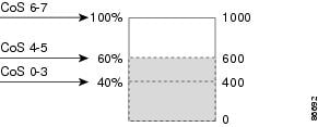
In a typical network, you connect a Cisco IP Phone to a switch port and cascade devices that generate data packets from the back of the telephone. The Cisco IP Phone guarantees the voice quality through a shared data link by marking the CoS level of the voice packets as high priority (CoS = 5) and by marking the data packets as low priority (CoS = 0). Traffic sent from the telephone to the switch is typically marked with a tag that uses the 802.1Q header. The header contains the VLAN information and the class of service (CoS) 3-bit field, which is the priority of the packet.

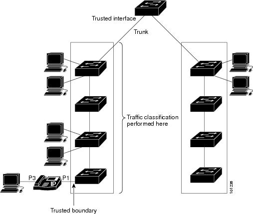
For most Cisco IP Phone configurations, the traffic sent from the telephone to the switch should be trusted to ensure that voice traffic is properly prioritized over other types of traffic in the network. By using the mls qos trust cos interface configuration command, you configure the switch port to which the telephone is connected to trust the CoS labels of all traffic received on that port. Use the mls qos trust dscp interface configuration command to configure a routed port to which the telephone is connected to trust the DSCP labels of all traffic received on that port.

With the trusted setting, you also can use the trusted boundary feature to prevent misuse of a high-priority queue if a user bypasses the telephone and connects the PC directly to the switch. Without trusted boundary, the CoS labels generated by the PC are trusted by the switch (because of the trusted CoS setting). By contrast, trusted boundary uses CDP to detect the presence of a Cisco IP Phone (such as the Cisco IP Phone 7910, 7935, 7940, and 7960) on a switch port. If the telephone is not detected, the trusted boundary feature disables the trusted setting on the switch port and prevents misuse of a high-priority queue. Note that the trusted boundary feature is not effective if the PC and Cisco IP Phone are connected to a hub that is connected to the switch.

SUMMARY STEPS

  1. configure terminal
  2. cdp run
  3. interface interface-id
  4. cdp enable
  5. Use one of the following:
    • mls qos trust cos
    • mls qos trust dscp
  6. mls qos trust device cisco-phone
  7. end
  8. show mls qos interface
  9. copy running-config startup-config

DETAILED STEPS

  Command or Action Purpose
Step 1

configure terminal

Example:


Switch# configure terminal

Enters the global configuration mode.

Step 2

cdp run

Example:


Switch(config)# cdp run

Enables CDP globally. By default, CDP is enabled.

Step 3

interface interface-id

Example:


Switch(config)# interface 
gigabitethernet0/1

Specifies the port connected to the Cisco IP Phone, and enters interface configuration mode.

Valid interfaces include physical ports.

Step 4

cdp enable

Example:


Switch(config-if)# cdp enable

Enables CDP on the port. By default, CDP is enabled.

Step 5

Use one of the following:

  • mls qos trust cos
  • mls qos trust dscp

Example:


Switch(config-if)# mls qos trust cos

Configures the switch port to trust the CoS value in traffic received from the Cisco IP Phone.

or

Configures the routed port to trust the DSCP value in traffic received from the Cisco IP Phone.

By default, the port is not trusted.

Step 6

mls qos trust device cisco-phone

Example:


Switch(config-if)# mls qos trust 
device cisco-phone

Specifies that the Cisco IP Phone is a trusted device.

You cannot enable both trusted boundary and auto-QoS (auto qos voip interface configuration command) at the same time; they are mutually exclusive.

Note 

To disable the trusted boundary feature, use the no mls qos trust device interface configuration command.

Step 7

end

Example:


Switch(config-if)# end

Returns to privileged EXEC mode.

Step 8

show mls qos interface

Example:


Switch# show mls qos interface

Verifies your entries.

Step 9

copy running-config startup-config

Example:


Switch# copy running-config 
startup-config

(Optional) Saves your entries in the configuration file.

Enabling DSCP Transparency Mode

The switch supports the DSCP transparency feature. It affects only the DSCP field of a packet at egress. By default, DSCP transparency is disabled. The switch modifies the DSCP field in an incoming packet, and the DSCP field in the outgoing packet is based on the quality of service (QoS) configuration, including the port trust setting, policing, and marking.

If DSCP transparency is enabled by using the no mls qos rewrite ip dscp command, the switch does not modify the DSCP field in the incoming packet, and the DSCP field in the outgoing packet is the same as that in the incoming packet.

Regardless of the DSCP transparency configuration, the switch modifies the internal DSCP value of the packet, which the switch uses to generate a class of service (CoS) value that represents the priority of the traffic. The switch also uses the internal DSCP value to select an egress queue and threshold.

SUMMARY STEPS

  1. configure terminal
  2. mls qos
  3. no mls qos rewrite ip dscp
  4. end
  5. show mls qos interface [interface-id]
  6. copy running-config startup-config

DETAILED STEPS

  Command or Action Purpose
Step 1

configure terminal

Example:


Switch# configure terminal

Enters global configuration mode.

Step 2

mls qos

Example:


Switch(config)# mls qos

Enables QoS globally.

Step 3

no mls qos rewrite ip dscp

Example:


Switch(config)# no mls qos rewrite ip dscp

Enables DSCP transparency. The switch is configured to not modify the DSCP field of the IP packet.

Step 4

end

Example:


Switch(config)# end

Returns to privileged EXEC mode.

Step 5

show mls qos interface [interface-id]

Example:


Switch# show mls qos interface gigabitethernet0/1

Verifies your entries.

Step 6

copy running-config startup-config

Example:


Switch# copy running-config startup-config

(Optional) Saves your entries in the configuration file.

DSCP Transparency Mode

To configure the switch to modify the DSCP value based on the trust setting or on an ACL by disabling DSCP transparency, use the mls qos rewrite ip dscp global configuration command.

If you disable QoS by using the no mls qos global configuration command, the CoS and DSCP values are not changed (the default QoS setting).

If you enter the no mls qos rewrite ip dscp global configuration command to enable DSCP transparency and then enter the mls qos trust [cos | dscp] interface configuration command, DSCP transparency is still enabled.


Note

For Catalyst 2960-L switches, DSCP transparency is disabled by default.


Configuring the DSCP Trust State on a Port Bordering Another QoS Domain

If you are administering two separate QoS domains between which you want to implement QoS features for IP traffic, you can configure the switch ports bordering the domains to a DSCP-trusted state. The receiving port accepts the DSCP-trusted value and avoids the classification stage of QoS. If the two domains use different DSCP values, you can configure the DSCP-to-DSCP-mutation map to translate a set of DSCP values to match the definition in the other domain.

Figure 9. DSCP-Trusted State on a Port Bordering Another QoS Domain

Beginning in privileged EXEC mode, follow these steps to configure the DSCP-trusted state on a port and modify the DSCP-to-DSCP-mutation map. To ensure a consistent mapping strategy across both QoS domains, you must perform this procedure on the ports in both domains.

SUMMARY STEPS

  1. configure terminal
  2. mls qos map dscp-mutation in-dscp to out-dscp
  3. interface interface-id
  4. mls qos trust dscp
  5. end
  6. show mls qos maps dscp-mutation
  7. copy running-config startup-config

DETAILED STEPS

  Command or Action Purpose
Step 1

configure terminal

Example:


Switch# configure terminal

Enters the global configuration mode.

Step 2

mls qos map dscp-mutation in-dscp to out-dscp

Example:


Switch(config)# mls qos map 
dscp-mutation 
10 11 12 13 to 30

Modifies the DSCP-to-DSCP-mutation map.

The default DSCP-to-DSCP-mutation map is a null map, which maps an incoming DSCP value to the same DSCP value.

  • For in-dscp , enter up to eight DSCP values separated by spaces. Then enter the to keyword.

  • For out-dscp , enter a single DSCP value.

The DSCP range is 0 to 63.

Step 3

interface interface-id

Example:


Switch(config)# interface 
gigabitethernet0/2

Specifies the port to be trusted, and enter interface configuration mode.

Valid interfaces include physical ports.

Step 4

mls qos trust dscp

Example:


Switch(config-if)# mls qos trust dscp

Configures the ingress port as a DSCP-trusted port. By default, the port is not trusted.

Note 

To return a port to its non-trusted state, use the no mls qos trust interface configuration command.

Step 5

end

Example:


Switch(config-if)# end

Returns to privileged EXEC mode.

Step 6

show mls qos maps dscp-mutation

Example:


Switch# show mls qos maps 
dscp-mutation

Verifies your entries.

Step 7

copy running-config startup-config

Example:


Switch# copy-running-config 
startup-config

(Optional) Saves your entries in the configuration file.

Note 

To return a port to its non-trusted state, use the no mls qos trust interface configuration command. To return to the default DSCP-to-DSCP-mutation map values, use the no mls qos map dscp-mutation dscp-mutation-name global configuration command.

Configuring a QoS Policy

Configuring a QoS policy typically requires the following tasks:

  • Classifying traffic into classes

  • Configuring policies applied to those traffic classes

  • Attaching policies to ports

These sections describe how to classify, police, and mark traffic. Depending on your network configuration, you must perform one or more of the modules in this section.

Classifying Traffic by Using ACLs

You can classify IP traffic by using IPv4 standard ACLS, IPv4 extended ACLs, or IPv6 ACLs.

You can classify non-IP traffic by using Layer 2 MAC ACLs.

Creating an IP Standard ACL for IPv4 Traffic

Before you begin

Before you perform this task, determine which access lists you will be using for your QoS configuration.

SUMMARY STEPS

  1. configure terminal
  2. access-list access-list-number {permit} source [source-wildcard]
  3. end
  4. show access-lists
  5. copy running-config startup-config

DETAILED STEPS

  Command or Action Purpose
Step 1

configure terminal

Example:

Switch# configure terminal

Enters global configuration mode.

Step 2

access-list access-list-number {permit} source [source-wildcard]

Example:

Switch(config)# access-list 1 
permit 192.2.255.0 1.1.1.255

Creates an IP standard ACL, repeating the command as many times as necessary.

  • For access-list-number , enter the access list number. The range is 1 to 99 and 1300 to 1999.

  • Use the permit keyword to permit a certain type of traffic if the conditions are matched.

  • For source , enter the network or host from which the packet is being sent. You can use the any keyword as an abbreviation for 0.0.0.0 255.255.255.255.

  • (Optional) For source-wildcard , enter the wildcard bits in dotted decimal notation to be applied to the source. Place ones in the bit positions that you want to ignore.

When you create an access list, remember that by default the end of the access list contains an implicit deny statement for everything if it did not find a match before reaching the end.

Note 

To delete an access list, use the no access-list access-list-number global configuration command.

Step 3

end

Example:

Switch(config)# end

Returns to privileged EXEC mode.

Step 4

show access-lists

Example:
Switch# show access-lists

Verifies your entries.

Step 5

copy running-config startup-config

Example:

Switch# copy-running-config 
startup-config

(Optional) Saves your entries in the configuration file.

Creating an IP Extended ACL for IPv4 Traffic

Before you begin

Before you perform this task, determine which access lists you will be using for your QoS configuration.

SUMMARY STEPS

  1. configure terminal
  2. access-list access-list-number permit protocol source source-wildcard destination destination-wildcard
  3. end
  4. show access-lists
  5. copy running-config startup-config

DETAILED STEPS

  Command or Action Purpose
Step 1

configure terminal

Example:

Switch# configure terminal

Enters global configuration mode.

Step 2

access-list access-list-number permit protocol source source-wildcard destination destination-wildcard

Example:

Switch(config)# access-list 100 permit ip any any dscp 32

Creates an IP extended ACL, repeating the command as many times as necessary.

  • For access-list-number , enter the access list number. The range is 100 to 199 and 2000 to 2699.

  • Use the permit keyword to permit a certain type of traffic if the conditions are matched.

  • For protocol , enter the name or number of an IP protocol. Use the question mark (?) to see a list of available protocol keywords.

  • For source , enter the network or host from which the packet is being sent. You specify this by using dotted decimal notation, by using the any keyword as an abbreviation for source 0.0.0.0 source-wildcard 255.255.255.255, or by using the host keyword for source 0.0.0.0.

  • For source-wildcard , enter the wildcard bits by placing ones in the bit positions that you want to ignore. You specify the wildcard by using dotted decimal notation, by using the any keyword as an abbreviation for source 0.0.0.0 source-wildcard 255.255.255.255, or by using the host keyword for source 0.0.0.0.

  • For destination , enter the network or host to which the packet is being sent. You have the same options for specifying the destination and destination-wildcard as those described by source and source-wildcard .

When creating an access list, remember that, by default, the end of the access list contains an implicit deny statement for everything if it did not find a match before reaching the end.

Note 

To delete an access list, use the no access-list access-list-number global configuration command.

Step 3

end

Example:

Switch(config)# end

Returns to privileged EXEC mode.

Step 4

show access-lists

Example:
Switch# show access-lists

Verifies your entries.

Step 5

copy running-config startup-config

Example:
Switch# copy-running-config 
startup-config

(Optional) Saves your entries in the configuration file.

Creating an IPv6 ACL for IPv6 Traffic

Before you begin

Before you perform this task, determine which access lists you will be using for your QoS configuration.

SUMMARY STEPS

  1. configure terminal
  2. ipv6 access-list access-list-name
  3. {permit} protocol {source-ipv6-prefix/prefix-length | any | host source-ipv6-address} 
[operator [port-number]] {destination-ipv6-prefix / prefix-length | any | host destination-ipv6-address} [operator [port-number]] [dscp value]
  4. end
  5. show ipv6 access-list
  6. copy running-config startup-config

DETAILED STEPS

  Command or Action Purpose
Step 1

configure terminal

Example:

Switch# configure terminal

Enters global configuration mode.

Step 2

ipv6 access-list access-list-name

Example:

Switch(config)# ipv6 
access-list ipv6_Name_ACL

Creates an IPv6 ACL and enters IPv6 access-list configuration mode.

Accesses list names cannot contain a space or quotation mark or begin with a numeric.

Note 

To delete an access list, use the no ipv6 access-list access-list-number global configuration command.

Step 3

{permit} protocol {source-ipv6-prefix/prefix-length | any | host source-ipv6-address} 
[operator [port-number]] {destination-ipv6-prefix / prefix-length | any | host destination-ipv6-address} [operator [port-number]] [dscp value]

Example:

Switch(config-ipv6-acl)# 
permit ip host 10::1 host 
11::2 host

Enters permit to permit the packet if conditions are matched. These are the conditions:

For protocol , enter the name or number of an Internet protocol: ahp , esp , icmp , ipv6 , pcp , stcp , tcp , or udp , or an integer in the range 0 to 255 representing an IPv6 protocol number.

  • The source-ipv6-prefix/prefix-length or destination-ipv6-prefix/ prefix-length is the source or destination IPv6 network or class of networks for which to set permit condition, specified in hexadecimal and using 16-bit values between colons (see RFC 2373).

  • Enter any as an abbreviation for the IPv6 prefix ::/0.

  • For host source-ipv6-address or destination-ipv6-address , enter the source or destination IPv6 host address for which to set permit condition, specified in hexadecimal using 16-bit values between colons.

  • (Optional) For operator , specify an operand that compares the source or destination ports of the specified protocol. Operands are lt (less than), gt (greater than), eq (equal), neq (not equal), and range .

    If the operator follows the source-ipv6-prefix/prefix-length argument, it must match the source port. If the operator follows the destination-ipv6- prefix/prefix-length argument, it must match the destination port.

  • (Optional) The port-number is a decimal number from 0 to 65535 or the name of a TCP or UDP port. You can use TCP port names only when filtering TCP. You can use UDP port names only when filtering UDP.

  • (Optional) Enter dscp value to match a differentiated services code point value against the traffic class value in the Traffic Class field of each IPv6 packet header. The acceptable range is from 0 to 63.

Step 4

end

Example:

Switch(config-ipv6-acl)# end

Returns to privileged EXEC mode.

Step 5

show ipv6 access-list

Example:

Switch# show ipv6 
access-list

Verifies the access list configuration.

Step 6

copy running-config startup-config

Example:

Switch# copy-running-config 
startup-config

(Optional) Saves your entries in the configuration file.

Creating a Layer 2 MAC ACL for Non-IP Traffic

Before you begin

Before you perform this task, determine that Layer 2 MAC access lists are required for your QoS configuration.

SUMMARY STEPS

  1. configure terminal
  2. mac access-list extended name
  3. {permit | deny} {host src-MAC-addr mask | any | host dst-MAC-addr | dst-MAC-addr mask} [type mask]
  4. end
  5. show access-lists [access-list-number | access-list-name]
  6. copy running-config startup-config

DETAILED STEPS

  Command or Action Purpose
Step 1

configure terminal

Example:

Switch# configure terminal

Enters global configuration mode.

Step 2

mac access-list extended name

Example:

Switch(config)# mac access-list 
extended maclist1

Creates a Layer 2 MAC ACL by specifying the name of the list.

After entering this command, the mode changes to extended MAC ACL configuration.

Note 

To delete an access list, use the no mac access-list extended access-list-name global configuration command.

Step 3

{permit | deny} {host src-MAC-addr mask | any | host dst-MAC-addr | dst-MAC-addr mask} [type mask]

Example:

Switch(config-ext-mac1) # permit 0001.0000.0001 
0.0.0 0002.0000.0001 0.0.0


Switch(config-ext-mac1) # permit 0001.0000.0002 
0.0.0 0002.0000.0002 0.0.0 xns-idp

Specifies the type of traffic to permit or deny if the conditions are matched, entering the command as many times as necessary.

  • For src-MAC-addr , enter the MAC address of the host from which the packet is being sent. You specify this by using the hexadecimal format (H.H.H), by using the any keyword as an abbreviation for source 0.0.0, source-wildcard ffff.ffff.ffff, or by using the host keyword for source 0.0.0.

  • For mask , enter the wildcard bits by placing ones in the bit positions that you want to ignore.

  • For dst-MAC-addr , enter the MAC address of the host to which the packet is being sent. You specify this by using the hexadecimal format (H.H.H), by using the any keyword as an abbreviation for source 0.0.0, source-wildcard ffff.ffff.ffff, or by using the host keyword for source 0.0.0.

  • (Optional) For type mask , specify the Ethertype number of a packet with Ethernet II or SNAP encapsulation to identify the protocol of the packet. For type , the range is from 0 to 65535, typically specified in hexadecimal. For mask , enter the don’t care bits applied to the Ethertype before testing for a match.

When creating an access list, remember that, by default, the end of the access list contains an implicit deny statement for everything if it did not find a match before reaching the end.

Step 4

end

Example:

Switch(config-ext-mac1)# end

Returns to privileged EXEC mode.

Step 5

show access-lists [access-list-number | access-list-name]

Example:

Switch# show access-lists

Verifies your entries.

Step 6

copy running-config startup-config

Example:

Switch# copy-running-config 
startup-config

(Optional) Saves your entries in the configuration file.

Classifying Traffic by Using Class Maps

You use the class-map global configuration command to name and to isolate a specific traffic flow (or class) from all other traffic. The class map defines the criteria to use to match against a specific traffic flow to further classify it. Match statements can include criteria such as an ACL or DSCP values. The match criterion is defined with one match statement entered within the class-map configuration mode.


Note

You can also create class maps during policy map creation by using the class policy-map configuration command.


SUMMARY STEPS

  1. configure terminal
  2. Use one of the following:
    • access-list access-list-number {permit} source [source-wildcard]
    • access-list access-list-number {permit} protocol source [source-wildcard] destination [destination-wildcard]
    • ipv6 access-list access-list-name {permit} protocol {source-ipv6-prefix/prefix-length | any | host source-ipv6-address} 
[operator [port-number]] {destination-ipv6-prefix / prefix-length | any | host destination-ipv6-address} [operator [port-number]] [dscp value]
    • mac access-list extended name {permit | deny} {host src-MAC-addr mask | any | host dst-MAC-addr | dst-MAC-addr mask} [type mask]
  3. class-map [match-all ] class-map-name
  4. match {access-group acl-index-or-name | ip dscp dscp-list}
  5. end
  6. show class-map
  7. copy running-config startup-config

DETAILED STEPS

  Command or Action Purpose
Step 1

configure terminal

Example:


Switch# configure terminal

Enters the global configuration mode.

Step 2

Use one of the following:

  • access-list access-list-number {permit} source [source-wildcard]
  • access-list access-list-number {permit} protocol source [source-wildcard] destination [destination-wildcard]
  • ipv6 access-list access-list-name {permit} protocol {source-ipv6-prefix/prefix-length | any | host source-ipv6-address} 
[operator [port-number]] {destination-ipv6-prefix / prefix-length | any | host destination-ipv6-address} [operator [port-number]] [dscp value]
  • mac access-list extended name {permit | deny} {host src-MAC-addr mask | any | host dst-MAC-addr | dst-MAC-addr mask} [type mask]

Example:


Switch(config)# access-list 103 permit ip any 
any dscp 10

Creates an IP standard or extended ACL, an IPv6 ACL for IP traffic, or a Layer 2 MAC ACL for non-IP traffic, repeating the command as many times as necessary.

When creating an access list, remember that, by default, the end of the access list contains an implicit deny statement for everything if it did not find a match before reaching the end.

Step 3

class-map [match-all ] class-map-name

Example:


Switch(config)# class-map class1

Creates a class map, and enters class-map configuration mode.

By default, no class maps are defined.

  • (Optional) Use the match-all keyword to perform a logical-AND of all matching statements under this class map. All match criteria in the class map must be matched.

  • For class-map-name , specify the name of the class map.

Note 

To delete an existing class map, use the no class-map [match-all ] class-map-name global configuration command.

Step 4

match {access-group acl-index-or-name | ip dscp dscp-list}

Example:


Switch(config-cmap)# match ip dscp 10 11 12

Defines the match criterion to classify traffic.

By default, no match criterion is defined.

Only one match criterion per class map is supported, and only one ACL per class map is supported.

  • For access-group acl-index-or-name, specify the number or name of the ACL created in Step 2.

  • To filter IPv6 traffic with the match access-group command, create an IPv6 ACL, as described in Step 2.

  • For ip dscp dscp-list , enter a list of up to eight IP DSCP values to match against incoming packets. Separate each value with a space. The range is 0 to 63.

Note 

To remove a match criterion, use the no match {access-group acl-index-or-name | ip dscp} class-map configuration command.

Step 5

end

Example:


Switch(config-cmap)# end

Returns to privileged EXEC mode.

Step 6

show class-map

Example:


Switch# show class-map

Verifies your entries.

Step 7

copy running-config startup-config

Example:


Switch# copy-running-config startup-config

(Optional) Saves your entries in the configuration file.

Classifying, Policing, and Marking Traffic on Physical Ports by Using Policy Maps

You can configure a policy map on a physical port that specifies which traffic class to act on. Actions can include trusting the CoS or DSCP values in the traffic class; setting a specific DSCP value in the traffic class; and specifying the traffic bandwidth limitations for each matched traffic class (policer) and the action to take when the traffic is out of profile (marking).

A policy map also has these characteristics:

  • A policy map can contain multiple class statements, each with different match criteria and policers.

  • A policy map can contain a predefined default traffic class explicitly placed at the end of the map.

  • A separate policy-map class can exist for each type of traffic received through a port.

Follow these guidelines when configuring policy maps on physical ports:

  • You can attach only one policy map per ingress port.

  • mls qos must be enabled in global configuration mode.

  • If you enter or have used the set ip dscp command, the switch changes this command to set dscp in its configuration.

  • A policy-map and a port trust state can both run on a physical interface. The policy-map is applied before the port trust state.

  • When you configure a default traffic class by using the class class-default policy-map configuration command, unclassified traffic (traffic that does not meet the match criteria specified in the traffic classes) is treated as the default traffic class (class-default).

SUMMARY STEPS

  1. configure terminal
  2. class-map class-map-name
  3. policy-map policy-map-name
  4. class [class-map-name | class-default]
  5. set dscp new-dscp
  6. police rate-bps burst-byte [exceed-action {drop}]
  7. exit
  8. exit
  9. interface interface-id
  10. service-policy input policy-map-name
  11. end
  12. show policy-map [policy-map-name [class class-map-name]]
  13. copy running-config startup-config

DETAILED STEPS

  Command or Action Purpose
Step 1

configure terminal

Example:


Switch# configure terminal

Enters the global configuration mode.

Step 2

class-map class-map-name

Example:


Switch(config)# class-map ipclass1

Creates a class map, and enters class-map configuration mode.

By default, no class maps are defined. For class-map-name , specify the name of the class map.

Step 3

policy-map policy-map-name

Example:


Switch(config-cmap)# policy-map flowit

Creates a policy map by entering the policy map name, and enters policy-map configuration mode.

By default, no policy maps are defined.

The default behavior of a policy map is to set the DSCP to 0 if the packet is an IP packet and to set the CoS to 0 if the packet is tagged. No policing is performed.

Note 

To delete an existing policy map, use the no policy-map policy-map-name global configuration command.

Step 4

class [class-map-name | class-default]

Example:


Switch(config-pmap)# class ipclass1

Defines a traffic classification, and enters policy-map class configuration mode.

By default, no policy map class-maps are defined.

If a traffic class has already been defined by using the class-map global configuration command, specify its name for class-map-name in this command.

A class-default traffic class is pre-defined and can be added to any policy. It is always placed at the end of a policy map. With an implied match any included in the class-default class, all packets that have not already matched the other traffic classes will match class-default .

Note 

To delete an existing class map, use the no class class-map-name policy-map configuration command.

Step 5

set dscp new-dscp

Example:


Switch(config-pmap-c)# set dscp 45

Classifies IP traffic by setting a new value in the packet.

  • For dscp new-dscp , enter a new DSCP value to be assigned to the classified traffic. The range is 0 to 63.

Step 6

police rate-bps burst-byte [exceed-action {drop}]

Example:


Switch(config-pmap-c)# police 100000 
80000 exceed-action drop

Defines a policer for the classified traffic.

By default, no policer is defined.

  • For rate-bps, specify average traffic rate in bits per second (b/s). The range is 8000 to 10000000000.

  • For burst-byte, specify the normal burst size in bytes.

    • If 8000 <= rate-bps < 102300000,burst-byte range is 8000 to 65535.

    • If 102300000 <= rate-bps <1023000000, burst-byte range is 8000 to 524280.

    • If 1023000000 <= rate-bps <= 10Gig, burst-byte range is 8000 to 1000000.

  • (Optional) Specifies the action to take when the rates are exceeded. Use the exceed-action drop keywords to drop the packet.

Note 

To remove an existing policer, use the no police rate-bps burst-byte [exceed-action drop ] policy-map configuration command.

Step 7

exit

Example:


Switch(config-pmap-c)# exit

Returns to policy map configuration mode.

Step 8

exit

Example:


Switch(config-pmap)# exit

Returns to global configuration mode.

Step 9

interface interface-id

Example:


Switch(config)# interface 
gigabitethernet0/1

Specifies the port to attach to the policy map, and enters interface configuration mode.

Valid interfaces include physical ports.

Step 10

service-policy input policy-map-name

Example:


Switch(config-if)# service-policy 
input flowit

Specifies the policy-map name, and applies it to an ingress port.

Only one policy map per ingress port is supported.

Note 

To remove the policy map and port association, use the no service-policy input policy-map-name interface configuration command.

Step 11

end

Example:


Switch(config-if)# end

Returns to privileged EXEC mode.

Step 12

show policy-map [policy-map-name [class class-map-name]]

Example:


Switch# show policy-map

Verifies your entries.

Step 13

copy running-config startup-config

Example:


Switch# copy-running-config 
startup-config

(Optional) Saves your entries in the configuration file.

Configuring Egress Queue Characteristics

Depending on the complexity of your network and your QoS solution, you might need to perform all of the tasks in the following modules. You need to make decisions about these characteristics:

  • Which packets are mapped by DSCP or CoS value to each queue and threshold ID?

  • What drop percentage thresholds apply to the queue-set (four egress queues per port), and how much reserved and maximum memory is needed for the traffic type?

  • Does the bandwidth of the port need to be rate limited?

  • How often should the egress queues be serviced and which technique (shaped, shared, or both) should be used?

Configuration Guidelines

Follow these guidelines when the expedite queue is enabled or the egress queues are serviced based on their SRR weights:

  • If the egress expedite queue is enabled, it overrides the SRR shaped and shared weights for queue 1.

  • If the egress expedite queue is disabled and the SRR shaped and shared weights are configured, the shaped mode overrides the shared mode for queue 1, and SRR services this queue in shaped mode.

  • If the egress expedite queue is disabled and the SRR shaped weights are not configured, SRR services this queue in shared mode.

Mapping DSCP or CoS Values to an Egress Queue and to a Threshold ID

You can prioritize traffic by placing packets with particular DSCPs or costs of service into certain queues and adjusting the queue thresholds so that packets with lower priorities are dropped. Default number of queues is 4. You can increase it to 8 using the mls qos srr-queue output queues 8 command.


Note

The egress queue default settings are suitable for most situations. You should change them only when you have a thorough understanding of egress queues and if these settings do not meet your QoS solution.


Beginning in privileged EXEC mode, follow these steps to map DSCP or CoS values to an egress queue and to a threshold ID. This procedure is optional.

SUMMARY STEPS

  1. configure terminal
  2. Use one of the following:
    • mls qos srr-queue output dscp-map queue queue-id threshold threshold-id dscp1...dscp8
    • mls qos srr-queue output cos-map queue queue-id threshold threshold-id cos1...cos8
  3. mls qos srr-queue output cos-map queue queue-id threshold threshold-id cos1...cos8
  4. end
  5. show mls qos maps
  6. copy running-config startup-config

DETAILED STEPS

  Command or Action Purpose
Step 1

configure terminal

Example:


Switch# configure terminal

Enters global configuration mode.

Step 2

Use one of the following:

  • mls qos srr-queue output dscp-map queue queue-id threshold threshold-id dscp1...dscp8
  • mls qos srr-queue output cos-map queue queue-id threshold threshold-id cos1...cos8

Example:


Switch(config)# mls qos srr-queue output 
dscp-map queue 1 threshold 2 10 11

Maps DSCP or CoS values to an egress queue and to a threshold ID.

By default, DSCP values 0–15 are mapped to queue 2 and threshold 1. DSCP values 16–31 are mapped to queue 3 and threshold 1. DSCP values 32–39 and 48–63 are mapped to queue 4 and threshold 1. DSCP values 40–47 are mapped to queue 1 and threshold 1.

By default, CoS values 0 and 1 are mapped to queue 2 and threshold 1. CoS values 2 and 3 are mapped to queue 3 and threshold 1. CoS values 4, 6, and 7 are mapped to queue 4 and threshold 1. CoS value 5 is mapped to queue 1 and threshold 1.

  • For queue-id , the range is 1 to 4.

  • For threshold-id , the range is 1 to 2. The drop-threshold percentage for threshold 3 is predefined. It is set to the queue-full state.

  • For dscp1...dscp8 , enter up to eight values, and separate each value with a space. The range is 0 to 63.

  • For cos1...cos8 , enter up to eight values, and separate each value with a space. The range is 0 to 7.

Note 

To return to the default DSCP output queue threshold map or the default CoS output queue threshold map, use the no mls qos srr-queue output dscp-map or the no mls qos srr-queue output cos-map global configuration command.

Step 3

mls qos srr-queue output cos-map queue queue-id threshold threshold-id cos1...cos8

Example:


Switch(config)# mls qos srr-queue output 
cos-map queue 3 threshold 1 2 3

Maps CoS values to an egress queue and to a threshold ID.

By default, CoS values 0 and 1 are mapped to queue 2 and threshold 1. CoS values 2 and 3 are mapped to queue 3 and threshold 1. CoS values 4, 6, and 7 are mapped to queue 4 and threshold 1. CoS value 5 is mapped to queue 1 and threshold 1.

  • For queue-id , the range is 1 to 4.

  • For threshold-id , the range is 1 to 2. The drop-threshold percentage for threshold 3 is predefined. It is set to the queue-full state.

  • For cos1...cos8 , enter up to eight values, and separate each value with a space. The range is 0 to 7.

Note 

To return to the default CoS output queue threshold map, use the no mls qos srr-queue output cos-map global configuration command.

Step 4

end

Example:


Switch(config)# end

Returns to privileged EXEC mode.

Step 5

show mls qos maps

Example:


Switch# show mls qos maps

Verifies your entries.

The DSCP output queue threshold map appears as a matrix. The d1 column specifies the most-significant digit of the DSCP number; the d2 row specifies the least-significant digit in the DSCP number. The intersection of the d1 and the d2 values provides the queue ID and threshold ID; for example, queue 2 and threshold 1 (02-01).

The CoS output queue threshold map shows the CoS value in the top row and the corresponding queue ID and threshold ID in the second row; for example, queue 2 and threshold 2 (2-2).

Step 6

copy running-config startup-config

Example:


Switch# copy-running-config 
startup-config

(Optional) Saves your entries in the configuration file.

To return to the default DSCP output queue threshold map or the default CoS output queue threshold map, use the no mls qos srr-queue output dscp-map or the no mls qos srr-queue output cos-map global configuration command.

Configuring SRR Shaped Weights on Egress Queues

You can specify how much of the available bandwidth is allocated to each queue. The ratio of the weights is the ratio of frequency in which the SRR scheduler sends packets from each queue.

You can configure the egress queues for shaped or shared weights, or both. Use shaping to smooth bursty traffic or to provide a smoother output over time.

Beginning in privileged EXEC mode, follow these steps to assign the shaped weights and to enable bandwidth shaping on the four egress queues mapped to a port. This procedure is optional.

SUMMARY STEPS

  1. configure terminal
  2. interface interface-id
  3. srr-queue bandwidth shape weight1 weight2 weight3 weight4
  4. end
  5. show mls qos interface interface-id queueing
  6. copy running-config startup-config

DETAILED STEPS

  Command or Action Purpose
Step 1

configure terminal

Example:


Switch# configure terminal

Enters the global configuration mode.

Step 2

interface interface-id

Example:


Switch(config)# interface gigabitethernet 0/1

Specifies the port of the outbound traffic, and enters interface configuration mode.

Step 3

srr-queue bandwidth shape weight1 weight2 weight3 weight4

Example:


Switch(config-if)# srr-queue 
bandwidth shape 8 0 0 0

Assigns SRR weights to the egress queues. By default, weight1 is set to 25; weight2, weight3, and weight4 are set to 0, and these queues are in shared mode.

For weight1 weight2 weight3 weight4 , enter the weights to control the percentage of the port that is shaped. The inverse ratio (1/weight) controls the shaping bandwidth for this queue. Separate each value with a space. The range is 0 to 65535.

If you configure a weight of 0, the corresponding queue operates in shared mode. The weight specified with the srr-queue bandwidth shape command is ignored, and the weights specified with the srr-queue bandwidth share interface configuration command for a queue come into effect. When configuring queues in the same queue-set for both shaping and sharing, make sure that you configure the lowest number queue for shaping.

The shaped mode overrides the shared mode.

To return to the default setting, use the no srr-queue bandwidth shape interface configuration command.

Step 4

end

Example:


Switch(config-if)# end

Returns to privileged EXEC mode.

Step 5

show mls qos interface interface-id queueing

Example:


Switch# show mls qos interface 
interface-id queuing

Verifies your entries.

Step 6

copy running-config startup-config

Example:


Switch# copy running-config 
startup-config

(Optional) Saves your entries in the configuration file.

To return to the default setting, use the no srr-queue bandwidth shape interface configuration command.

Configuring SRR Shared Weights on Egress Queues

In shared mode, the queues share the bandwidth among them according to the configured weights. The bandwidth is guaranteed at this level but not limited to it. For example, if a queue empties and does not require a share of the link, the remaining queues can expand into the unused bandwidth and share it among them. With sharing, the ratio of the weights controls the frequency of dequeuing; the absolute values are meaningless.


Note

The egress queue default settings are suitable for most situations. You should change them only when you have a thorough understanding of the egress queues and if these settings do not meet your QoS solution.


Beginning in privileged EXEC mode, follow these steps to assign the shared weights and to enable bandwidth sharing on the four egress queues mapped to a port. This procedure is optional.

SUMMARY STEPS

  1. configure terminal
  2. interface interface-id
  3. srr-queue bandwidth share weight1 weight2 weight3 weight4
  4. end
  5. show mls qos interface interface-id queueing
  6. copy running-config startup-config

DETAILED STEPS

  Command or Action Purpose
Step 1

configure terminal

Example:


Switch# configure terminal

Enters global configuration mode.

Step 2

interface interface-id

Example:


Switch(config)# interface 
gigabitethernet0/1

Specifies the port of the outbound traffic, and enters interface configuration mode.

Step 3

srr-queue bandwidth share weight1 weight2 weight3 weight4

Example:


Switch(config-id)# srr-queue 
bandwidth share 1 2 3 4

Assigns SRR weights to the egress queues. By default, all four weights are 25 (1/4 of the bandwidth is allocated to each queue).

For weight1 weight2 weight3 weight4 , enter the weights to control the ratio of the frequency in which the SRR scheduler sends packets. Separate each value with a space. The range is 1 to 255.

To return to the default setting, use the no srr-queue bandwidth share interface configuration command.

Step 4

end

Example:


Switch(config-id)# end

Returns to privileged EXEC mode.

Step 5

show mls qos interface interface-id queueing

Example:


Switch# show mls qos interface 
interface_id queuing

Verifies your entries.

Step 6

copy running-config startup-config

Example:


Switch# copy-running-config 
startup-config

(Optional) Saves your entries in the configuration file.

To return to the default setting, use the no srr-queue bandwidth share interface configuration command.

Configuring the Egress Expedite Queue

You can ensure that certain packets have priority over all others by queuing them in the egress expedite queue. SRR services this queue until it is empty before servicing the other queues.

Beginning in privileged EXEC mode, follow these steps to enable the egress expedite queue. This procedure is optional.

SUMMARY STEPS

  1. configure terminal
  2. mls qos
  3. interface interface-id
  4. priority-queue out
  5. end
  6. show running-config
  7. copy running-config startup-config

DETAILED STEPS

  Command or Action Purpose
Step 1

configure terminal

Example:


Switch# configure terminal

Enters global configuration mode.

Step 2

mls qos

Example:


Switch(config)# mls qos

Enables QoS on a switch.

Step 3

interface interface-id

Example:


Switch(config)# interface gigabitethernet 0/1

Specifies the egress port, and enters interface configuration mode.

Step 4

priority-queue out

Example:


Switch(config-if)# priority-queue out

Enables the egress expedite queue, which is disabled by default.

When you configure this command, the SRR weight and queue size ratios are affected because there is one fewer queue participating in SRR. This means that weight1 in the srr-queue bandwidth shape or the srr-queue bandwidth share command is ignored (not used in the ratio calculation).

Note 

To disable the egress expedite queue, use the no priority-queue out interface configuration command.

Step 5

end

Example:


Switch(config-if)# end

Returns to privileged EXEC mode.

Step 6

show running-config

Example:


Switch# show running-config

Verifies your entries.

Step 7

copy running-config startup-config

Example:


Switch# copy running-config 
startup-config

(Optional) Saves your entries in the configuration file.

To disable the egress expedite queue, use the no priority-queue out interface configuration command.

Limiting the Bandwidth on an Egress Interface

You can limit the bandwidth on an egress port. For example, if a customer pays only for a small percentage of a high-speed link, you can limit the bandwidth to that amount.


Note

The egress queue default settings are suitable for most situations. You should change them only when you have a thorough understanding of the egress queues and if these settings do not meet your QoS solution.


Beginning in privileged EXEC mode, follow these steps to limit the bandwidth on an egress port. This procedure is optional.

SUMMARY STEPS

  1. configure terminal
  2. interface interface-id
  3. srr-queue bandwidth limit weight1
  4. end
  5. show mls qos interface [interface-id] queueing
  6. copy running-config startup-config

DETAILED STEPS

  Command or Action Purpose
Step 1

configure terminal

Example:


Switch# configure terminal

Enters global configuration mode.

Step 2

interface interface-id

Example:


Switch(config)# interface gigabitethernet 0/1

Specifies the port to be rate-limited, and enters interface configuration mode.

Step 3

srr-queue bandwidth limit weight1

Example:


Switch(config-if)# srr-queue 
bandwidth limit 80

Specifies the percentage of the port speed to which the port should be limited. The range is 10 to 90.

By default, the port is not rate-limited and is set to 100 percent.

Note 
To return to the default setting, use the no srr-queue bandwidth limit interface configuration command.
Step 4

end

Example:


Switch(config-if)# end

Returns to privileged EXEC mode.

Step 5

show mls qos interface [interface-id] queueing

Example:


Switch# show mls qos interface 
interface_id queueing

Verifies your entries.

Step 6

copy running-config startup-config

Example:


Switch# copy-running-config 
startup-config

(Optional) Saves your entries in the configuration file.

To return to the default setting, use the no srr-queue bandwidth limit interface configuration command.

Monitoring Standard QoS

Table 5. Commands for Monitoring Standard QoS on the Switch

Command

Description

show mls qos

Displays global QoS configuration information.

show mls qos interface [interface-id] [ policers | queueing | statistics]

Displays QoS information at the port level, including the buffer allocation, which ports have configured policers, the queueing strategy, and the ingress and egress statistics.

show mls qos maps [cos-output-q | dscp-mutation ]

Displays QoS mapping information.

show running-config | include rewrite

Displays the DSCP transparency setting.

Configuration Examples for QoS

Example: Configuring Port to the DSCP-Trusted State and Modifying the DSCP-to-DSCP-Mutation Map

This example shows how to configure a port to the DSCP-trusted state and to modify the DSCP-to-DSCP-mutation map so that incoming DSCP values 10 to 13 are mapped to DSCP 30:


Switch(config)# mls qos map dscp-mutation 
10 11 12 13 to 30 
Switch(config)# interface gigabitethernet0/2
Switch(config-if)# mls qos trust dscp
Switch(config-if)# end

Examples: Classifying Traffic by Using ACLs

This example shows how to allow access for only those hosts on the three specified networks. The wildcard bits apply to the host portions of the network addresses. Any host with a source address that does not match the access list statements is rejected.


Switch(config)# access-list 1 permit 192.5.255.0 0.0.0.255
Switch(config)# access-list 1 permit 128.88.0.0 0.0.255.255
Switch(config)# access-list 1 permit 36.0.0.0 0.0.0.255
! (Note: all other access implicitly denied)

This example shows how to create an ACL that permits IP traffic from any source to any destination that has the DSCP value set to 32:


Switch(config)# access-list 100 permit ip any any dscp 32

This example shows how to create an ACL that permits IP traffic from a source host at 10.1.1.1 to a destination host at 10.1.1.2 with a precedence value of 5:


Switch(config)# access-list 100 permit ip host 10.1.1.1 host 10.1.1.2 precedence 5

This example shows how to create an ACL that permits PIM traffic from any source to a destination group address of 224.0.0.2 with a DSCP set to 32:


Switch(config)# access-list 102 permit pim any 224.0.0.2 dscp 32

This example shows how to create an ACL that permits IPv6 traffic from any source to any destination that has the DSCP value set to 32:


Switch(config)# ipv6 access-list 100 permit ip any any dscp 32

This example shows how to create an ACL that permits IPv6 traffic from a source host at 10.1.1.1 to a destination host at 10.1.1.2 with a precedence value of 5:


Switch(config)# ipv6 access-list ipv6_Name_ACL permit ip host 10::1 host 10.1.1.2 
precedence 5

This example shows how to create a Layer 2 MAC ACL with two permit statements. The first statement allows traffic from the host with MAC address 0001.0000.0001 to the host with MAC address 0002.0000.0001. The second statement allows only Ethertype XNS-IDP traffic from the host with MAC address 0001.0000.0002 to the host with MAC address 0002.0000.0002.


Switch(config)# mac access-list extended maclist1
Switch(config-ext-macl)# permit 0001.0000.0001 0.0.0 0002.0000.0001 0.0.0
Switch(config-ext-macl)# permit 0001.0000.0002 0.0.0 0002.0000.0002 0.0.0 xns-idp
! (Note: all other access implicitly denied)

Examples: Classifying Traffic by Using Class Maps

This example shows how to configure the class map called class1. The class1 has one match criterion, which is access list 103. It permits traffic from any host to any destination that matches a DSCP value of 10.


Switch(config)# access-list 103 permit ip any any dscp 10
Switch(config)# class-map class1
Switch(config-cmap)# match access-group 103
Switch(config-cmap)# end
Switch#

This example shows how to create a class map called class2, which matches incoming traffic with DSCP values of 10, 11, and 12.


Switch(config)# class-map class2
Switch(config-cmap)# match ip dscp 10 11 12
Switch(config-cmap)# end
Switch#

This example shows how to configure a class map to match IP DSCP and IPv6:


Switch(config)# Class-map cm-1
Switch(config-cmap)# match ip dscp 10
Switch(config-cmap)# exit
Switch(config)# Class-map cm-2
Switch(config-cmap)# match ip dscp 20
Switch(config-cmap)# exit
Switch(config)# Policy-map pm1
Switch(config-pmap)# class cm-1
Switch(config-pmap-c)# set dscp 4
Switch(config-pmap-c)# exit
Switch(config-pmap)# class cm-2
Switch(config-pmap-c)# set dscp 6
Switch(config-pmap-c)# exit
Switch(config-pmap)# exit
Switch(config)# interface G1/0/1
Switch(config-if)# service-policy input pm1

This example shows how to configure a class map that applies to both IPv4 and IPv6 traffic:


Switch(config)# ip access-list 101 permit ip any any
Switch(config)# ipv6 access-list ipv6-any permit ip any any
Switch(config)# Class-map cm-1
Switch(config-cmap)# match access-group 101
Switch(config-cmap)# exit
Switch(config)# class-map cm-2
Switch(config-cmap)# match access-group name ipv6-any
Switch(config-cmap)# exit
Switch(config)# Policy-map pm1
Switch(config-pmap)# class cm-1
Switch(config-pmap-c)# set dscp 4
Switch(config-pmap-c)# exit
Switch(config-pmap)# class cm-2
Switch(config-pmap-c)# set dscp 6
Switch(config-pmap-c)# exit
Switch(config-pmap)# exit
Switch(config)# interface G0/1
Switch(config-if)# switch mode access
Switch(config-if)# service-policy input pm1

Examples: Classifying, Policing, and Marking Traffic on Physical Ports Using Policy Maps

This example shows how to create a policy map and attach it to an ingress port. In the configuration, the IP standard ACL permits traffic from network 10.1.0.0. For traffic matching this classification, the DSCP value in the incoming packet is trusted. If the matched traffic exceeds an average traffic rate of 48000 b/s and a normal burst size of 8000 bytes, its DSCP is marked down (based on the policed-DSCP map) and sent:


Switch(config)# access-list 1 permit 10.1.0.0 0.0.255.255
Switch(config)# class-map ipclass1
Switch(config-cmap)# match access-group 1
Switch(config-cmap)# exit
Switch(config)# policy-map flow1t
Switch(config-pmap)# class ipclass1
Switch(config-pmap-c)# set dscp cs1
Switch(config-pmap-c)# police 1000000 8000 exceed-action drop
Switch(config-pmap-c)# exit
Switch(config-pmap)# exit
Switch(config)# interface gigabitethernet 0/1
Switch(config-if)# service-policy input flow1t

This example shows how to create a Layer 2 MAC ACL with two permit statements and attach it to an ingress port. The first permit statement allows traffic from the host with MAC address 0001.0000.0001 destined for the host with MAC address 0002.0000.0001. The second permit statement allows only Ethertype XNS-IDP traffic from the host with MAC address 0001.0000.0002 destined for the host with MAC address 0002.0000.0002.


Switch(config)# mac access-list extended maclist1
Switch(config-ext-mac)# permit 0001.0000.0001 0.0.0 0002.0000.0001 0.0.0
Switch(config-ext-mac)# permit 0001.0000.0002 0.0.0 0002.0000.0002 0.0.0 xns-idp
Switch(config-ext-mac)# exit
Switch(config)# mac access-list extended maclist2
Switch(config-ext-mac)# permit 0001.0000.0003 0.0.0 0002.0000.0003 0.0.0
Switch(config-ext-mac)# permit 0001.0000.0004 0.0.0 0002.0000.0004 0.0.0 aarp
Switch(config-ext-mac)# exit
Switch(config)# class-map macclass1
Switch(config-cmap)# match access-group maclist1
Switch(config-cmap)# exit
Switch(config)# policy-map macpolicy1
Switch(config-pmap)# class macclass1
Switch(config-pmap-c)# set dscp 63
Switch(config-pmap-c)# exit
Switch(config-pmap)# class macclass2 maclist2
Switch(config-pmap-c)# set dscp 45
Switch(config-pmap-c)# exit
Switch(config-pmap)# exit
Switch(config)# interface gigabitethernet 0/1
Switch(config-if)# mls qos trust cos
Switch(config-if)# service-policy input macpolicy1

This example shows how to create a class map that applies to both IPv4 and IPv6 traffic with the default class applied to unclassified traffic:


Switch(config)# ip access-list 101 permit ip any any
Switch(config)# ipv6 access-list ipv6-any permit ip any any
Switch(config)# class-map cm-1
Switch(config-cmap)# match access-group 101
Switch(config-cmap)# exit
Switch(config)# class-map cm-2
Switch(config-cmap)# match access-group name ipv6-any
Switch(config-cmap)# exit
Switch(config)# policy-map pm1
Switch(config-pmap)# class cm-1
Switch(config-pmap-c)# set dscp 4
Switch(config-pmap-c)# exit
Switch(config-pmap)# class cm-2
Switch(config-pmap-c)# set dscp 6
Switch(config-pmap-c)# exit
Switch(config-pmap)# class class-default
Switch(config-pmap-c)# set dscp 10
Switch(config-pmap-c)# exit
Switch(config-pmap)# exit
Switch(config)# interface G0/1
Switch(config-if)# switch mode access
Switch(config-if)# service-policy input pm1

Examples: Configuring DSCP-to-DSCP Mutation Maps

This example shows how to define the DSCP-to-DSCP-mutation map. All the entries that are not explicitly configured are not modified (remains as specified in the null map):


Switch(config)# mls qos map dscp-mutation 1 2 3 4 5 6 7 to 0
Switch(config)# mls qos map dscp-mutation 8 9 10 11 12 13 to 10
Switch(config)# mls qos map dscp-mutation 20 21 22 to 20
Switch(config)# mls qos map dscp-mutation 30 31 32 33 34 to 30
Switch(config)# interface gigabitethernet 0/1
Switch(config-if)# mls qos trust dscp
Switch(config-if)# end
Switch# show mls qos maps dscp-mutation 
Dscp-dscp mutation map:
   mutation1:
     d1 :  d2 0  1  2  3  4  5  6  7  8  9
     ---------------------------------------
      0 :    00 00 00 00 00 00 00 00 10 10
      1 :    10 10 10 10 14 15 16 17 18 19
      2 :    20 20 20 23 24 25 26 27 28 29
      3 :    30 30 30 30 30 35 36 37 38 39
      4 :    40 41 42 43 44 45 46 47 48 49
      5 :    50 51 52 53 54 55 56 57 58 59
      6 :    60 61 62 63


Note

In the above DSCP-to-DSCP-mutation map, the mutated values are shown in the body of the matrix. The d1 column specifies the most-significant digit of the original DSCP; the d2 row specifies the least-significant digit of the original DSCP. The intersection of the d1 and d2 values provides the mutated value. For example, a DSCP value of 12 corresponds to a mutated value of 10.


Examples: Configuring Egress Queue Characteristics

This example shows how to configure bandwidth shaping on queue 1. Because the weight ratios for queues 2, 3, and 4 are set to 0, these queues operate in shared mode. The bandwidth weight for queue 1 is 1/8, which is 12.5 percent:


Switch(config)# interface gigabitethernet 0/1
Switch(config-if)# srr-queue bandwidth shape 8 0 0 0

This example shows how to configure the weight ratio of the SRR scheduler running on an egress port. Four queues are used, and the bandwidth ratio allocated for each queue in shared mode is 1/(1+2+3+4), 2/(1+2+3+4), 3/(1+2+3+4), and 4/(1+2+3+4), which is 10 percent, 20 percent, 30 percent, and 40 percent for queues 1, 2, 3, and 4. This means that queue 4 has four times the bandwidth of queue 1, twice the bandwidth of queue 2, and one-and-a-third times the bandwidth of queue 3.


Switch(config)# interface gigabitethernet 0/1
Switch(config-if)# srr-queue bandwidth share 1 2 3 4

This example shows how to enable the egress expedite queue when the SRR weights are configured. The egress expedite queue overrides the configured SRR weights.


Switch(config)# interface gigabitethernet 0/1
Switch(config-if)# srr-queue bandwidth shape 25 0 0 0
Switch(config-if)# srr-queue bandwidth share 30 20 25 25
Switch(config-if)# priority-queue out
Switch(config-if)# end

This example shows how to limit the bandwidth on a port to 80 percent:


Switch(config)# interface gigabitethernet 0/1
Switch(config-if)# srr-queue bandwidth limit 80

When you configure this command to 80 percent, the port is idle 20 percent of the time. The line rate drops to 80 percent of the connected speed, which is 800 Mb/s. These values are not exact because the hardware adjusts the line rate in increments of six.

Where to Go Next

Review the auto-QoS documentation to see if you can use these automated capabilities for your QoS configuration.

Feature History and Information for QoS

Release Modification

Cisco IOS Release 15.2(5)E

This feature was introduced.