The documentation set for this product strives to use bias-free language. For the purposes of this documentation set, bias-free is defined as language that does not imply discrimination based on age, disability, gender, racial identity, ethnic identity, sexual orientation, socioeconomic status, and intersectionality. Exceptions may be present in the documentation due to language that is hardcoded in the user interfaces of the product software, language used based on RFP documentation, or language that is used by a referenced third-party product. Learn more about how Cisco is using Inclusive Language.
This table provides release and platform support information for the features explained in this module.
These features are available in all the releases subsequent to the one they were introduced in, unless noted otherwise.
Release
Feature name and description
Supported platform
Cisco IOS XE 17.18.1
SISF: SISF is a framework for optimizing security in Layer 2 domains. It merges the IPDT and certain IPv6 FHS functionality,
to simplify the migration from IPv4 to IPv6 stack or a dual-stack.
Cisco C9350 Series Smart Switches
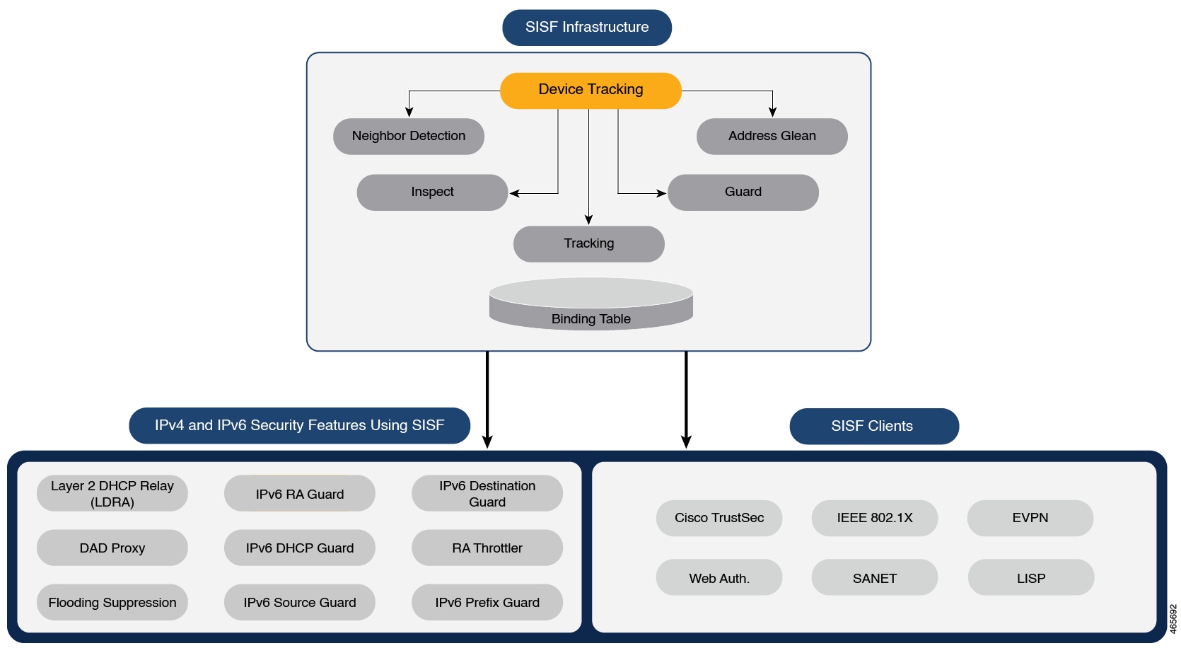
Understand SISF
Switch Integrated Security Features (SISF) is a framework for optimizing security in Layer 2 domains. It merges the IP Device
Tracking (IPDT) and certain IPv6 first-hop security (FHS) functionality1, to simplify the migration from IPv4 to IPv6 stack or a dual-stack.
The SISF infrastructure provides a unified database that is used by:
Cisco TrustSec, IEEE 802.1X, Locator ID Separation Protocol (LISP), Ethernet VPN (EVPN), and Web Authentication act as clients
for SISF.
The figure illustrates the SISF Framework.
Figure 1. SISF Framework
Note
The terms SISF, device-tracking, and SISF-based device-tracking are used interchangeably in this document and refer to the same feature. Neither term is used to mean or should be confused
with the legacy IPDT or IPv6 Snooping features.
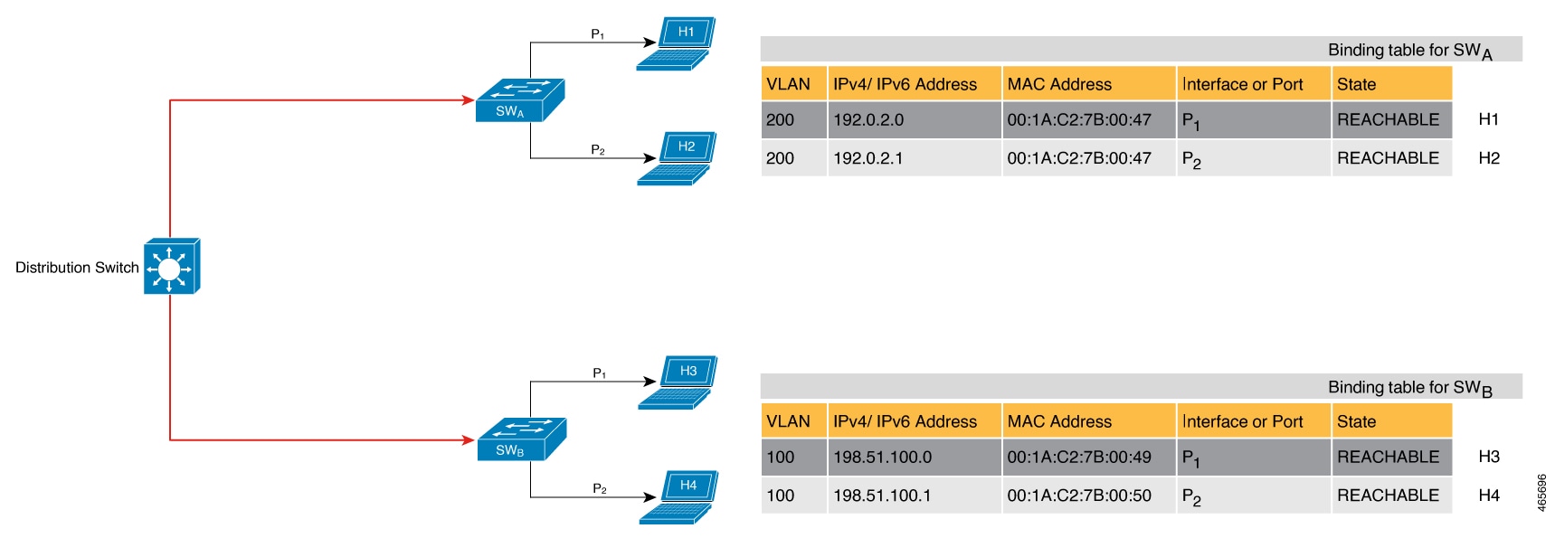
The binding table
The SISF infrastructure is built around the binding table. The binding table contains information about the hosts that are
connected to the ports of a switch and the IP and MAC address of these hosts. This action creates a physical map of all the
hosts connected to a switch.
Each entry in a binding table provides the following information about a connected host:
IPv4 or IPv6 address of the host.
MAC address of the host. The same MAC address may be linked to an IPv4 and IPv6 address.
The interface or port on the switch that the host is connected to, and the associated VLAN.
The state of the entry, which indicates the reachability of the entry.
The figure shows a simple network topology and a representative binding table for each access switch in the network. SWA and SWB are the two access switches in the network. The two access switches are connected to the same distribution switch. H1, H2,
H3, H4 are the hosts.
This example shows a distributed binding table where each access switch in the network has its table. An alternative setup
could be one centralized binding table on the distribution switch containing entries of SWAand SWB.
Having a distributed or a centralized binding table is a key design choice in the process of implementing SISF in your network
and is covered in greater detail in the Understand policy parameters section.
Figure 2. Binding table
(Click on the image to see the details more clearly.)
States and lifetime of a binding table entry
The state of an entry shows whether the host is reachable. The binding table entry can be in stable states such as REACHABLE,
DOWN, and STALE. When changing from one state to another, an entry may have other temporary or transitional states such as:
VERIFY, INCOMPLETE, and TENTATIVE.
The duration an entry stays in a state depends on its lifetime and successful validation. The lifetime of an entry can be
policy-driven or configured globally.
To configure the REACHABLE, DOWN, and STALE lifetimes, enter the command in global configuration mode.
For DHCP-originated entries, the above configuration does not apply as the DHCP lease time overrides the SISF stale-lifetime
and down-lifetime configuration that are globally defined or specified by the policy.
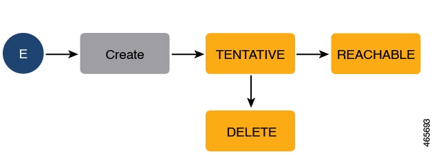
State: Reachable
If an entry is in this state, it means the host (IP and MAC address) is verified and valid. A reachable entry has a default
lifetime of five minutes. You can also configure a duration. By configuring a reachable-lifetime, you specify how long a host
can remain in a REACHABLE state, after the last incoming control packet from that host.
If an event is detected before the entry’s reachable lifetime expires, then the reachable lifetime is reset.
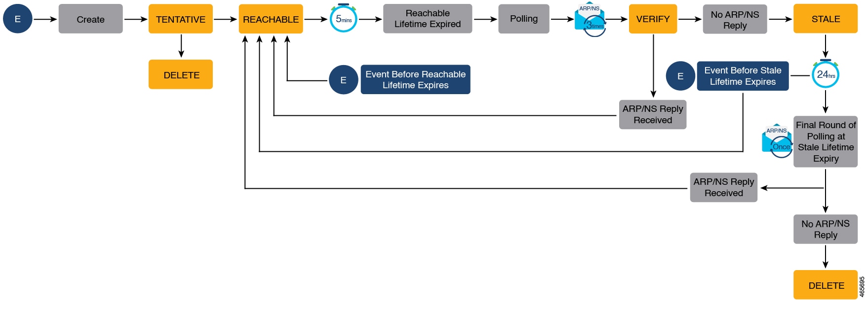
To qualify for the REACHABLE state, a new entry goes through the process illustrated in the figure below. The switch detects
an event (E), such as an incoming control packet from a connected host and creates an entry. Various events cause the creation
of an entry, and these are described in the Binding table sources section. After creating an entry, it goes through transient states like TENTATIVE or INCOMPLETE. While in a transitional
state, the switch validates and confirms the integrity of the binding entry. If the entry is found to be valid, then the state
changes to REACHABLE.
But if an address theft or similar event is detected, then the entry is regarded as invalid and is deleted. For example, if
an attacker sends unsolicited neighbor advertisement messages with the same IP as the target IP and their own MAC address
to redirect traffic.
Figure 3. Creation of a reachable entry
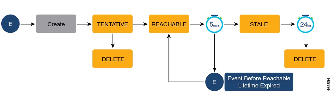
State: Stale
If an entry is in this state it means that the entry’s reachable lifetime has expired and the corresponding host is still
silent (no incoming packets from the host). A stale entry has a default lifetime of 24 hours. You can also configure a duration.
The system deletes an entry if it stays in the STALE state beyond its stale lifetime.
This is illustrated in the figure below which depicts the lifecycle of an entry.
Figure 4. Lifecycle of an entry
State: Down
If an entry is in this state, it means that the host’s connecting interface is down. A down entry has a default lifetime of
24 hours. Additionally, you can configure a duration. An entry is deleted if it remains in the DOWN state beyond its down
lifetime.
Poll a host and update the binding table entry
Polling involves checking whether the host is connected and communicating. In addition to determining an entry’s state, you
can use polling to reconfirm an entry's state.
You can enable polling with the device-tracking tracking command in global configuration mode. After you do, you still have the flexibility to turn polling on or off for a particular
interface or VLAN. For this, configure the tracking enable or tracking disable keywords in the policy (the device-tracking configuration mode). When polling is enabled, the switch polls the host at the
specified interval, thus reconfirming its reachability for the duration of its reachable lifetime.
When polling is enabled, the switch sends up to three polling requests after the reachable lifetime expires at intervals determined
by the system. You can also configure this interval with the device-tracking tracking retry-intervalseconds command in global configuration mode.
The figure below depicts the lifecycle of an entry where the host is polled. Default reachable and stale lifetimes, and retry
intervals are used in figure:
When an event (E) is detected, a REACHABLE entry is created.
If an event is detected during the reachable lifetime, the reachable lifetime timer is reset.
The switch sends a polling request after the reachable lifetime expires. The switch polls the host up to three times at fixed,
system-determined intervals. The polling request may be in the form of a unicast Address Resolution Protocol (ARP) probe or
a Neighbor Solicitation message. During this time, the system changes the entry state to VERIFY. If a polling response is
received (thus confirming reachability of the host), the state of the entry changes back to REACHABLE.
If the switch does not receive a polling response after three attempts, the entry changes to the STALE state. It remains in
this state for 24 hours. If an event is detected during the stale lifetime, the state of the entry is changed back to REACHABLE.
At expiry of the stale lifetime, the device sends one final polling to ascertain reachability. If this final polling attempt
receives a reply, the state of the entry is changed back to REACHABLE. If the final polling attempt does not receive a response,
the entry is deleted.
Figure 5. Lifecycle of an entry where the host is polled
(Click on the image to see the details more clearly.)
The DHCP lease time determines how long a DHCP-originated binding remains valid in the table. When the DHCP lease time expires,
the entry is removed from the table without additional reachability probes.
Binding table sources
The following are the sources of information and events that cause the creation and update of a binding table entry:
Learning events that dynamically populate the binding table:
Dynamic Host Configuration Protocol (DHCP) negotiation (DHCP REQUEST, and DHCP REPLY). This includes DHCPv4 and DHCPv6.
Address Resolution Protocol (ARP) packets.
ARP packets are throttled to mitigate high CPU utilization scenarios. Within a five-second window, a maximum of 50 ARP packets
from the same source are processed by SISF. Note that the limit of 50 in five seconds is for each binding entry, that is,
for each source IP.
All ARP (ARP REQUEST and ARP REPLY) packets are dropped if
the limit is reached and
the security level of the device tracking policy is set to guard.
Neighbor Discovery Protocol (NDP) packets.
Multiple Identity Association-Nontemporary Address (IA_NA) and Identity Association-Prefix Delegation (IA_PD).
In some cases, a network device can request and receive more than one IPv6 address from the DHCP server. This may be done
to provide addresses to multiple clients of the device, such as when a residential gateway requests addresses to distribute
to network clients. When the device sends a DHCPv6 packet, it includes all of the addresses that have been assigned to the
device.
When SISF analyzes a DHCPv6 packet, it examines the IA_NA (Identity Association-Nontemporary Address) and IA_PD (Identity
Association-Prefix Delegation) components of the packet and extracts each IPv6 address contained in the packet. SISF adds
each extracted address to the binding table.
Entries created through learning events are called dynamic entries. These entries, shown in the device-tracking database details
output, are prefixed with abbreviations that indicate the type of learning event, such as "ARP" for ARP packets.
Configuring static binding entries.
If there are silent but reachable hosts in the Layer 2 domain, you can create static binding entries to retain binding information
even if the host becomes silent.
Manually add a static binding entry to the binding table using this command in global configuration mode:
Static entries in the show device-tracking database details output are prefixed with the letter "S".
You can configure a reachable lifetime for a static entry. The stale and down lifetime timer is fixed by the system as infinite (for an entry in the STALE or DOWN state, the output of the show device-tracking database command displays the Time Left column as “N/A”). When a static entry enters the STALE or DOWN state, it remains in this state indefinitely in the binding
table.
A static entry can be removed from the binding table only by the actions listed below. It cannot be deleted from the binding
table by using clear commands or by any other event:
Remove the entry by configuring the no form of the above command.
A local entry replaces the static entry.
A local entry is an entry that is automatically created by the system when you configure an SVI on the device. When configuring
the SVI, if you use the same IP address as the static entry then the static entry is replaced with the local entry, because
the local entry has a higher priority.
In the output of the show device-tracking database details privileged EXEC command, local entries are prefixed with the letter "L".
For more information about static binding entries, see the device-tracking binding command in the command reference.
Note
A specific scenario allows a ping to result in a device-tracking entry. If a sender’s ARP cache or IPv6 neighbor table does
not have the target’s IP address yet, then a ping triggers an ARP packet for IPv4, or ND packet for IPv6. This can result
in a device-tracking entry.
But if the target IP is already in the ARP cache or IPv6 neighbour table, no ARP or ND packet is generated when you ping,
in which case SISF cannot learn the IP address.
Actions on a packet and the binding table
The distinction between system behaviour in the context of a binding table entry and system behaviour in the context of a
packet (from which the binding information is extracted) is an important one, because the available actions are exclusive
to each context.
SISF actions determine if any features can access, use, or forward a packet.
Stop: Means the packet is not available to any client or feature.
A packet may be stopped while the binding integrity of a possible entry is being verified. From a system perspective, this
action is equivalent to dropping a packet. However, from a SISF perspective, the packet might not be considered malicious,
as SISF attempts to extract binding information from it.
Forward: Means the packet is allowed to enter the network and is sent on, unchanged.
Drop: Means the packet is not allowed to enter the network.
SISF actions on the binding table include only the items listed here.
Create or update: Means the packet or other source is used to create or update an entry in the binding table.
Ignore: Means the packet or other source of information is disregarded and there is no change or update in the binding table.
Multiple actions can be performed on a packet. If both the stop and ignore actions occur, a drop may also happen. If stop and update actions are observed, the packet is allowed to enter the network and is sent on, unchanged.
Device-tracking
SISF-based device-tracking is disabled by default. You can enable the feature on an interface or VLAN.
When you enable the feature, the binding table is created, followed by subsequent maintenance of the binding table.
The events listed in the Binding table sources section trigger SISF-based device-tracking to monitor the presence, location, and movement of hosts in the network to populate
and maintain the binding table. For example, if information about a host is learned via an ARP or ND packet, each subsequent
ARP or ND packet from the same host alerts SISF-based device-tracking to refresh the entry in the binding table, indicating
whether the host remains in the same location or has moved.
The switch continuously snoops packets, extracts device identities (MAC and IP addresses), and stores them in the binding
table. This process ensures binding integrity and maintains the reachability status of hosts.
Device-tracking policy
A device-tracking policy is a set of rules that SISF-based device-tracking follows. The policy outlines which events to monitor,
whether a host is probed, the time to wait before probing the host. These rules are referred to as policy parameters.
Note
The policy must be attached to an interface or VLAN. Only then is the binding table for that interface or VLAN populated,
in accordance with policy parameters.
To display policy settings, use the show device-tracking policy policy_name command in privileged EXEC mode.
Understand policy parameters
Policy parameters are keywords for configuring the device-tracking mode. Each parameter enhances network security.
This section explains the purpose of some of the important policy parameters so you can configure your policy to better suit your requirements.
For detailed information about parameters in the device-tracking configuration mode, refer to the command reference document
for the release.
Glean versus guard versus inspect
SISF extracts the IP and MAC addresses from a packet entering the network and dictates the subsequent action according to
the security-level configured in the policy.
You can choose one of these options for the security-level parameter: glean, guard, or inspect. Glean is the least secure,
followed by Inspect, and Guard is the most secure option.
To configure this parameter in a policy, enter the security-level keyword in the device-tracking configuration mode.
Glean
When the security-level is set to glean, SISF extracts the IP and MAC address and enters them into the binding table, without any verification. This option therefore
does not ensure binding integrity. It may for example, be suited to a set-up where client applications such as IEEE 802.1X
or SANET want to only learn about the host and not rely on SISF for authentication.
The address count limit is the only factor affecting the addition of a binding entry for this security-level. There are separate
limits for the maximum number of IPs per port, IPv4 per MAC, and IPv6 per MAC. Entries are rejected once a limit is reached.
For more information about this parameter, refer Address count limits.
Guard
This is the default value for the security-level parameter.
When the security-level is set to guard, SISF extracts and verifies the IP and MAC address of packets entering the network. The outcome of the verification determines
whether a binding entry is added, updated, or if the packet is dropped and the client rejected.
Verification begins by searching for a matching entry in the database. The database may be centralised or distributed. If
a matching entry is not found, a new entry is added.
If a matching entry is found and the points of attachment (MAC, VLAN, or interface) are found to be the same, only the timestamp
is updated. If not, the scope of verification is extended to include validation of address ownership. This may include host
polling to determine if the change in the point of attachment (a different MAC, or VLAN) is valid. If the change is valid
the entry is updated, or if it is a case of theft, the entry is not added to the binding table.
If a binding entry is added or updated, the corresponding client is granted access to the network. If an entry does not pass
verification, the corresponding client is rejected.
Note
The verification process affects the binding entry and the corresponding incoming packet.
Inspect
Even though security-level inspect is available on the CLI, we recommend not using it. The glean and guard options described above address most use cases and network requirements.
The security level policy parameter can affect actions on ND and ARP packets: If the security level is set to guard and the packet does not pass verification, a drop action follows. If its glean, the packet is not dropped. Verification failure
(with the guard security level) can be because of various reasons including invalid binding information, reaching the address count limit,
and so on.
Trusted-port and device-role switch
The device-role switch and trusted-port options help you design an efficient and scalable secure zone. When used together, these two parameters help you achieve
an efficient distribution of the creation of entries in the binding table. This keeps the size of the binding tables under
control.
The trusted-port option: Disables the guard function on configured targets. Bindings learned through a trusted-port have preference over bindings
learned through any other port. A trusted port is also given preference in case of a collision while making an entry in the
table.
The device-role option: Indicates the type of device that is facing the port and this can be a node or a switch. To allow the creation of
binding entries for a port, you configure the device as a node. To stop the creation of binding entries, you configure the
device as switch.
Configuring the device as a switch is suitable for multi-switch setups, where there is a high possibility of large device-tracking
tables. Here, a port facing a device (an uplink trunk port) can be configured to stop creating binding entries, and the traffic
arriving at such a port can be trusted, because the switch on the other side of the trunk port will have device-tracking enabled
and that will have checked the validity of the binding entry.
Note
In most cases, configure both the trusted-port and device-role switch options on the port - the examples below explain this in detail. Possible scenarios where only either one of these options
is suited or required have also been described, at the end of this section.
To configure these parameters in a policy, use the trusted-port and device-role keywords in the device-tracking configuration mode.
Trusted-port and device-role switch options in a multi-switch set-up
This example explains how the device-role switch and trusted-port options help to design an efficient and scalable “secure zone”.
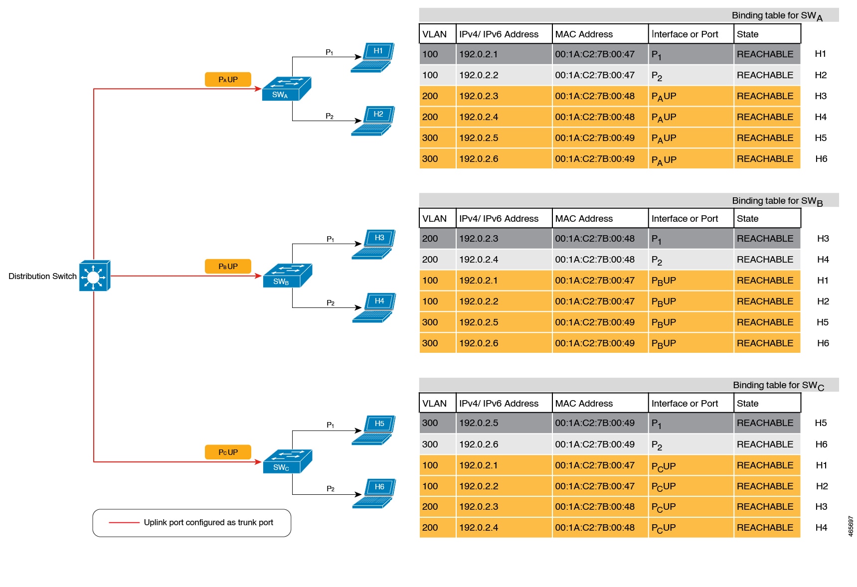
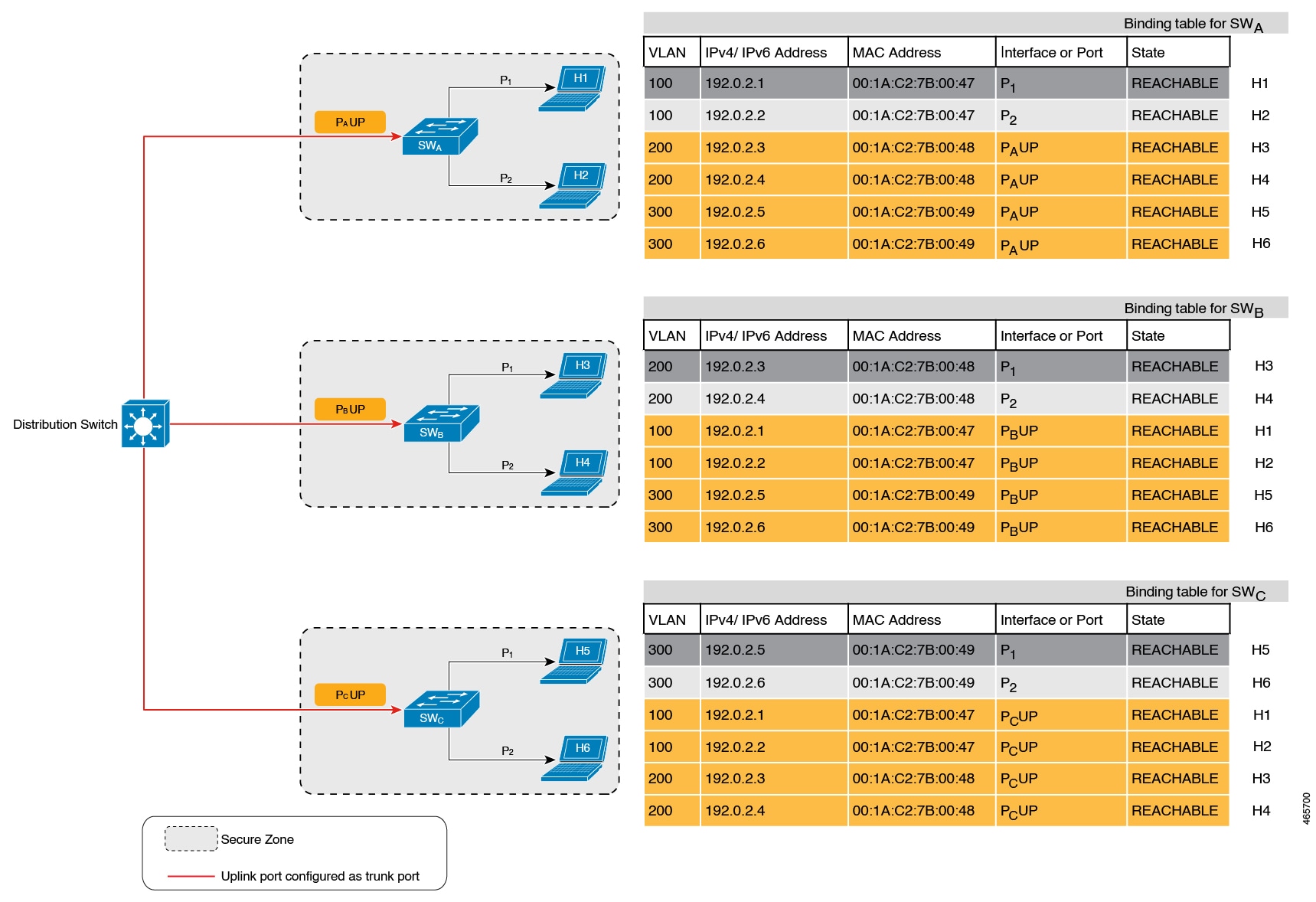
In figure Multi-switch set-ups without trusted-port and device-role switch options below, SWA, SWB, and SWC are three access switches. They are all connected to a common distribution switch. The only required configuration on the
distribution switch in this scenario is to ensure that traffic of any kind is not blocked.
H1, H2, …H6 are the hosts. Each switch has two directly connected hosts. All hosts are communicating with each other, that
is, control packets are being transmitted. All hosts are also within the same VLAN boundary. Each switch is receiving control
packets from hosts that are directly connected to it, and also from hosts that are connected to other switches. This means
SWA is receiving control packets from H1, H2, …H6 similarly with SWB and SWC.
For each switch, the entries of directly connected hosts have interface or port P1 and P2 in the binding table. Entries originating from hosts that are connected to other switches have interface or port name PxUP, to show that they have been learned through the uplink port (x represents the corresponding uplink port for each switch.
For example, the entries that SWA learns through its uplink port have interface or port name PAUP and for SWB it is PBUP, and so forth.
The end result is that each switch learns and creates binding entries for all hosts in the set-up.
This scenario displays an inefficient use of the binding table, because each host is being validated multiple times, which
does not make it more secure than if just one switch validates host. Secondly, entries for the same host in multiple binding
tables could mean that the address count limit is reached sooner. After the limit is reached, any further entries are rejected
and required entries may be missed this way.
Figure 6. Multi-switch set-ups without trusted-port and device-role switch options
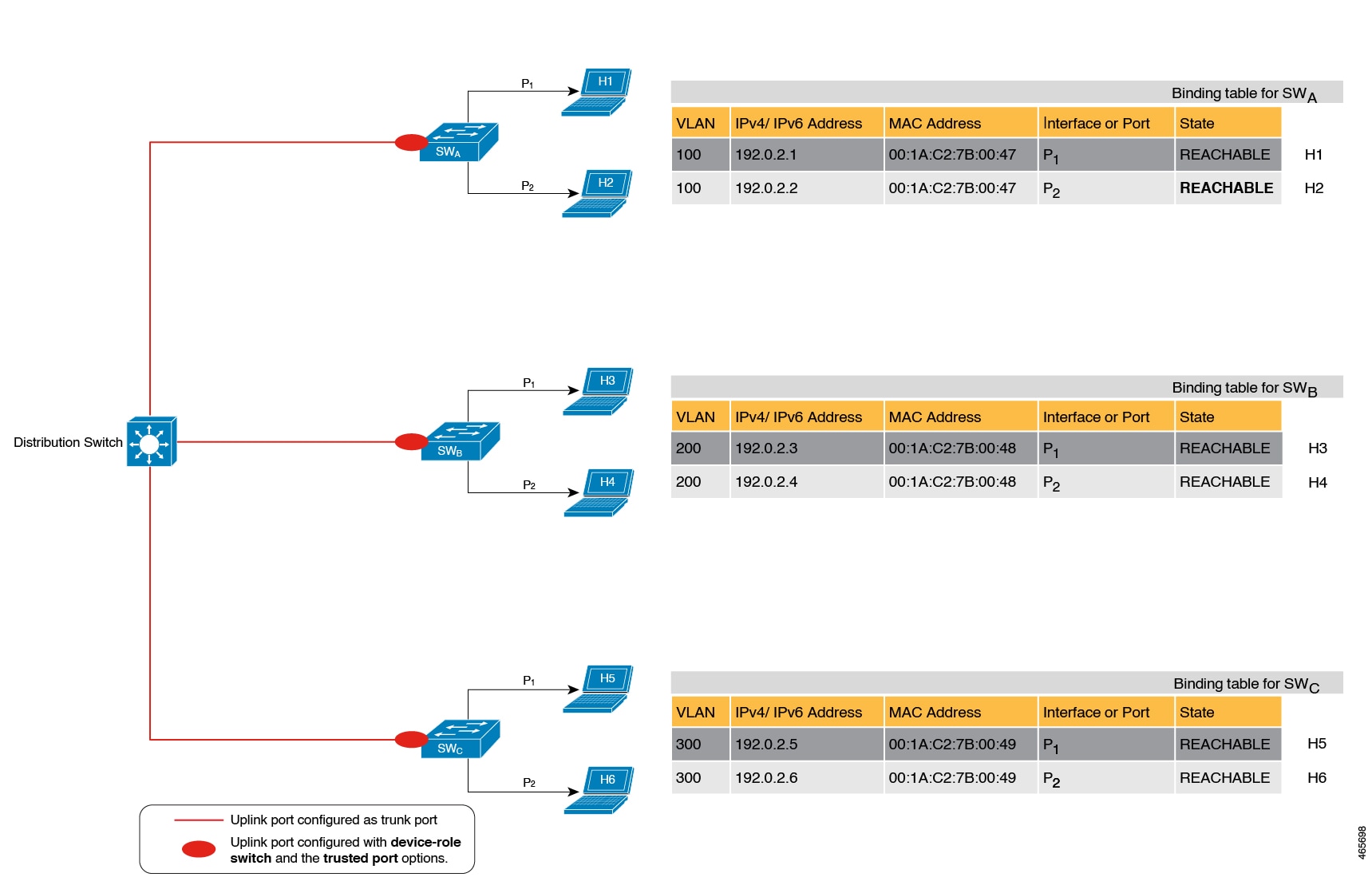
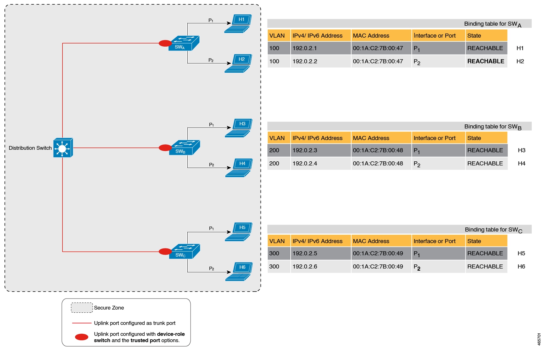
By contrast, see figure Multi-switch set-ups with trusted-port and device-role switch options below. Here, when SWA intercepts the packet of a host that is not attached to it (say H3 which is directly attached to SWB), it does not create an entry because it detects that H3 is attached to a device that is configured as a switch (device-role switch option) and the uplink port of the switch (where the packet came from) is a trusted port (trusted-port option).
By creating binding entries only on switches where the host appears on an access port (port P1 and P2 of each switch), and not creating entries for a host that appears over an uplink port or trusted port (Px UP), each switch in the set-up validates and makes only the required entries, thus achieving an efficient distribution of
the creation of binding table entries.
A second advantage of configuring device-role switch and trusted-port options in a multi-switch scenario is the prevention of duplicate entries when a host, such as H1, moves from one switch
to another H1’s IP and MAC binding in the earlier location (let’s say SWA) continues to remain there until it reaches the STALE state. But if H1 moves and connects to a second switch, say SWC, then SWA receives a duplicate binding entry through the uplink port. In such a situation, if the uplink port of the second switch
(SWC) is configured as a trusted port, SWA deletes its stale entry. Further, it doesn’t create another new binding entry because the SWC will already have the latest entry and this entry is trusted.
Figure 7. Multi-switch set-ups with trusted-port and device-role switch options
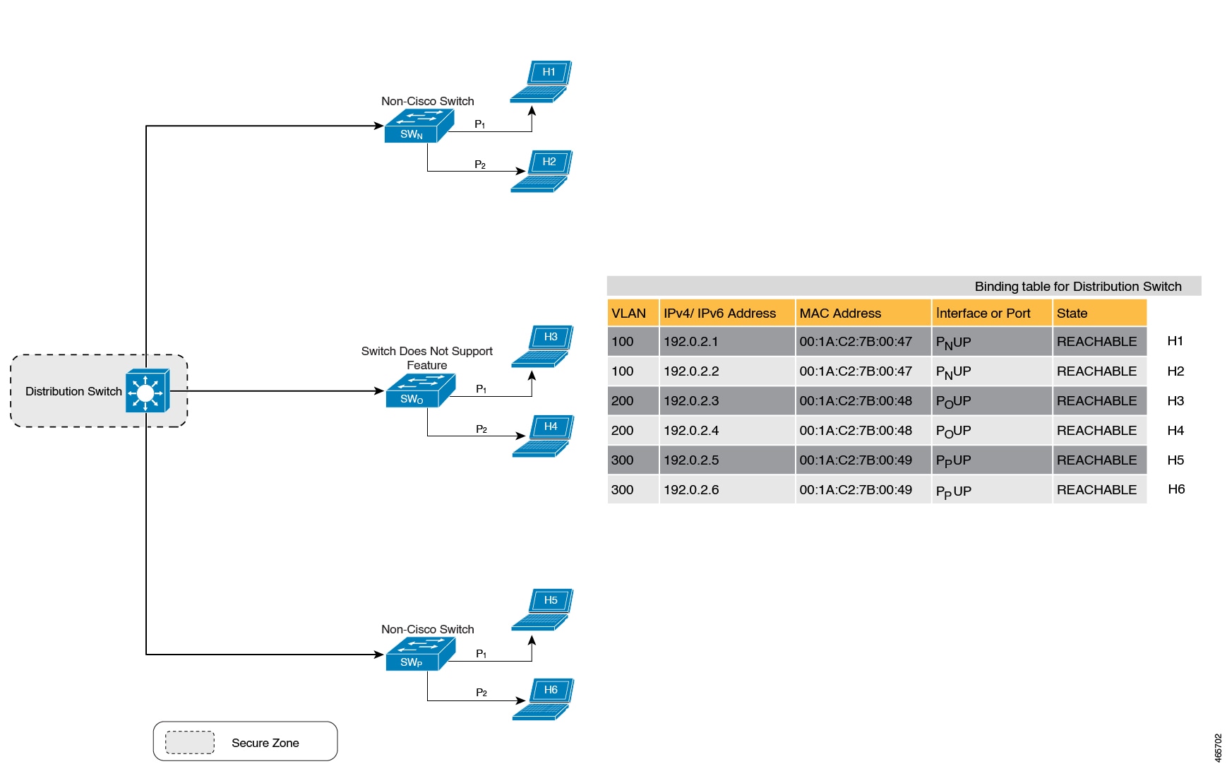
When not to use trusted-port and device-role switch options
While the previous example clarifies how a multi-switch set-up with distributed binding tables stands to benefit from the
device-role switch and trusted-port options, it may not suit networks of the following kinds:
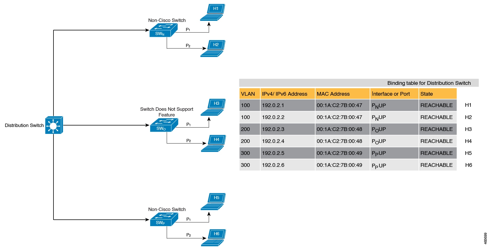
Networks where non-Cisco switches are being used
Networks where the switch does not support the SISF-based device-tracking feature.
In both cases, we recommended that you do not configure the device-role switch and trusted-port options. Further, we recommended that you maintain a centralized binding table - on the distribution switch. When you do,
all the binding entries for all the hosts connected to non-Cisco switches and switches that do not support the feature, are
validated by the distribution switch and still secure your network. The figure below illustrates the same.
Figure 8. Centralised binding table
When to use only trusted-port or device-role switch option
Configure only the device-role switch when you want to listen but not learn entries. For example, for Duplicate Address Detection (DAD) or when you want
to send IPv6 or Neighbor Solicitation (NS) messages on a switch-facing port.
When you configure this option on a switch port (or interface), SISF-based device-tracking treats the port as a trunk port,
implying that the port is connected to other switches. It is irrelevant whether the port is a trunk port. Therefore, when
NS packets or queries are sent to switches in the network for new entry validation, only the secure ports (ports where the
device-role switch is configured) receive the packet or query. This configuration safeguards the network. If the command is not configured on
any port, a general broadcast of the query is sent.
Configure only the trusted-port for situations where an access port should be a trusted port. If an access port is connected to a DHCP server or a similar
service that the switch is consuming, configuring an access port as a trusted port ensures that the service is not disrupted
because traffic from such a port is trusted. This setup also widens the secure zone to include the access port.
Efficient and scalable secure zone
Use the trusted-port and device-role switch options in appropriate networks to create an efficient and scalable secure zone.
Secure zones 1, 2, and 3 represent three setups, each demonstrating how the secure zone is established.
Secure zone:
Secure zone 1 - Inefficient and unscalable secure zone
Secure zone 2 - Efficient and scalable secure zone when binding tables are decentralized
Secure zone 3: Efficient secure zone when binding table is centralized
Scalability:
Unscalable; each switch has entries of all the hosts in the network
Scalable; each switch as entries of only directly connected hosts
Unscalable; the distribution switch has entries of all hosts in the network
Polling and its effect on the network:
n = number of hosts
m = number of switches
total number of polling requests: = n X m
18 polling requests are being sent (6 hosts x 3 switches).
Each host is polled by all the switches in the network (in the absence of the trusted-port and device-role switch options).
Network load is very high.
6 polling requests are being sent (2 hosts x 1 switch for each switch).
Minimal network load. (Polling requests are sent by the local access switches to directly connected hosts, each polling request
passes through fewer points in the network.)
6 polling requests are being sent (6 hosts x 1 switch)
Network load is higher than secure zone 2, but not as high as secure zone 1. (Polling requests come from the distribution
switch and go through the access switch before reaching the host.)
Efficiency:
The binding table is inefficient because it is duplicated on each switch.
Efficient binding table, because each host’s binding information is entered only once, and in one binding table and this the
binding table of the directly connected switch.
Efficient binding table, because the binding information for each host is entered only once, and this is in the central binding
table, which is on the distribution switch.
Recommended action:
Reapply suitable policies to make the secure zone like secure zone 2
None; this is an efficient and scalable secure zone.
None; this is the best possible secure zone given the type of set-up (where the other switches in the network are either non-Cisco
or do not support the feature)
Figure 9. Secure zone 1 - Inefficient and unscalable secure zone
Figure 10. Secure zone 2 - Efficient and scalable secure zone when binding tables are decentralized
Figure 11. Secure zone 3: Efficient secure zone when binding table is centralized
Address count limits
The address count limit parameter specifies how many IP and MAC addresses can be entered in a binding table. These limits
are determined based on known and expected hosts. This enables preemptive action against rogue hosts or IPs.
At a policy level, there are separate limits for IP addresses per port, IPv4 addresses per MAC, and IPv6 addresses per MAC.
Configure or change only the number of IP addresses per port.
IP per port
The IP per port option is the total number of IP addresses allowed for a port. The address can be IPv4 or IPv6. When the limit
is reached, no further IP addresses (i.e., entries) are added to the binding table.
To configure this parameter in a policy, enter the limit address-countip-per-port keyword in device-tracking configuration mode. If you configure a lower limit, it applies only to new entries. An existing
entry remains in the binding table and goes through its binding entry lifecycle.
IPv4 per MAC and IPv6 per MAC
This refers to the number of IPv4 addresses that can be mapped to one MAC address and the number of IPv6 addresses that can
be mapped to one MAC address. When the limit is reached, no further entries can be added to the binding table, and traffic
from new hosts will be dropped
Note
The IPv4 per MAC limit and the IPv6 per MAC limit that is effective on an interface or VLAN is as defined in the policy that
is applied. If the policy does not specify a limit, this means that a limit does not exist. Limit configuration for IPv4 per
MAC or IPv6 per MAC is not possible for programmatic, custom, or default policies.
Enter the show device-tracking policy policy name command to check if a limit exisits.
Here is an example output of a policy where an IPv4 per MAC and an IPv6 per MAC limit exists:
Device# show device-tracking policy LISP-DT-GUARD-VLAN

Policy LISP-DT-GUARD-VLAN configuration:
  security-level guard (*)
  <output truncated>

  limit address-count for IPv4 per mac 4 (*)
  limit address-count for IPv6 per mac 12 (*)
  tracking enable

<output truncated>
Address count limit and SISF action on the binding table
The address count limit parameter affects actions that are performed on the binding table: If a limit is reached, binding
entries are not added to the binding table. (It does not influence packet action).
Address count limit and interactions with other SISF settings
The limits do not have a hierarchy, but the threshold that is set for each limit affects the others.
For example, if the IP per port limit is 100, and the IPv4 per MAC limit is one, the limit is reached with a single host’s
IPv4-MAC binding entry. No further IP entries, which are bound to the same MAC are allowed in the table even though the port
has a provision for 99 more IP addresses. Similarly, if the IP per port limit is one, and the IPv4 per MAC limit is 100. The
limit is reached with a single host’s IPv4-MAC binding entry. No further IP entries are allowed in the table even though the
MAC has a provision for 99 more IP addresses for that MAC.
Global and policy-level limits
The limits configured with the device-tracking binding max-entries command are at the global level, the limits configured with the limit address-count command in the device-tracking configuration mode are for a policy, which is at the interface or VLAN level.
If a policy-level value and a globally configured value exists, the creation of binding entries is stopped when a limit is reached - this limit can be any one of the global values or the policy-level value.
If only globally configured values exist, the creation of binding entries is stopped when a limit is reached.
If the only policy-level value exists, the creation of binding entries is stopped when the policy-level limit is reached.
Tracking
The tracking parameter involves monitoring hosts in the network. In section States and lifetime of a binding table entry above, this is referred to as "polling" which is described in detail.
To configure polling parameters at the global level, enter the device-tracking tracking command in global configuration mode. After configuring this command, you can choose to turn polling on or off for individual
interfaces and VLANs. For this, you must enable or disable polling in the policy.
To enable polling in a policy, enter the tracking enable command in the device-tracking configuration mode. By default, polling is disabled in a policy.
Guidelines to create a policy
If you have multiple policies available on a given target, the system uses an internal policy priority to determine which
policy takes precedence.
A manually created policy has the highest priority. Therefore, a custom policy can be created to override the settings and
take precedence over a programmatically created policy.
The parameters of a programmatically created policy cannot be changed. You can configure certain attributes of a custom policy.
Guidelines to apply a policy
You can attach multiple policies to the same VLAN.
If a programmatic policy is attached to a VLAN and you wish to change the policy settings, create a custom device-tracking
policy and attach it to the VLAN.
If you attach multiple policies with different priorities to the same VLAN, the policy with the highest priority takes effect.
Exceptions include the limit address-count settings for IPv4 per MAC and IPv6 per MAC, where the settings of the policy with
the lowest priority are effective.
When you attach a device-tracking policy to an interface under a VLAN, the interface's policy settings prevail over those
of the VLAN. However, limit address-count values for IPv4 per MAC and IPv6 per MAC are aggregated from both policies.
You must remove the device tracking client feature configuration before you can remove a policy.
Configure SISF
By default, SISF or SISF-based device-tracking is disabled. You enable it by defining a device-tracking policy and attaching
the policy to a specific target. The target could be an interface or VLAN. Use the method that best suits your needs.
Method to enable SISF
Applicable configuration tasks
Result
Option 1: Manually, by using interface configuration commands to create and apply the default policy to a target.
Automatically applies the default device tracking policy to the specified target.
The default policy is a built-in policy with default settings; you cannot change any of the attributes of the default policy. See Option 2 if you want to configure device tracking policy attributes.
Option 2: Manually, by using global configuration commands to create a custom policy and applying the custom policy to a target.
When you configure the command, the system automatically creates policy DT-PROGRAMMATIC.
Use this method if you want to enable SISF-based device tracking for these clients: IEEE 802.1X, Web authentication, Cisco
TrustSec, IP Source Guard, and SANET.
Option 4: Programmatically, by configuring Locator ID Separation Protocol (LISP).
When you configure LISP, the system automatically creates policy LISP-DT-GUARD-VLAN, LISP-DT-GLEAN-VLAN, or other variants, depending on the software release.
Option 5: Programmatically, by configuring EVPN VLAN.
When you configure EVPN on VLAN, the system automatically creates policy evpn-sisf-policy, evpn-device-track, or other variants, depending on the software release.
By adding the policy to an interface template, you can apply the same policy to multiple targets, without having to create
it separately for each target.
Option 7: Migrating from legacy IPDT and IPv6 Snooping.
Convert legacy IPDT and IPv6 Snooping configuration to the SISF-based device-tracking commands.
Migrate from legacy IPDT and IPv6 Snooping to SISF-based device tracking
The device-tracking upgrade-cli global configuration command upgrades the CLI differently based on the legacy configuration that exists on your device. Consider
these configuration scenarios and migration results before updating your existing configuration:
Note
Avoid configuring both the old IPDT and IPv6 Snooping commands with the SISF-based device-tracking commands.
Only IPDT configuration exists
If your device has only IPDT configuration, running the device-tracking upgrade-cli command creates and attaches a SISF policy to the interface.
Continuing with legacy commands restricts operations to legacy modes, allowing only legacy IPDT and IPv6 Snooping commands
to work.
Only IPv6 snooping configuration exists
On a device with existing IPv6 Snooping configuration, you can configure further using the old IPv6 Snooping commands. Here
are the options you can choose from:
(Recommended) Use the device-tracking upgrade-cli command to convert all your legacy configuration to the SISF-based device-tracking commands. After conversion, your device
will support only SISF-based device-tracking commands.
Use the legacy IPv6 Snooping commands for your future configuration and do not run the device-tracking upgrade-cli command. With this option, only the legacy IPv6 Snooping commands are available on your device, and you cannot use the SISF-based
device-tracking commands.
Both IPDT and IPv6 snooping configuration exist
On a device that has both legacy IPDT configuration and IPv6 Snooping configuration, you can convert legacy commands to the
SISF-based device-tracking commands. However, note that only one snooping policy can be attached to an interface, and the
IPv6 Snooping policy parameters override the IPDT settings.
Note
If you do not migrate to the SISF-based device-tracking commands and continue to use the legacy IPv6 Snooping or IPDT commands,
your IPv4 device-tracking configuration information may be displayed in the IPv6 Snooping commands, as the SISF-based device-tracking
feature handles both IPv4 and IPv6 configuration. To avoid this, we recommend that you convert your legacy configuration to
SISF-based device-tracking commands.
No IPDT or IPv6 snooping configuration exists
If your device has no legacy IP Device Tracking or IPv6 Snooping configurations, you can use only the SISF-based device-tracking
commands for all your future configuration. The legacy IPDT commands and IPv6 Snooping commands are not available.
Apply the default device tracking policy to a target
Perform these steps to apply the default device tracking policy to an interface or VLAN:
Procedure
Command or Action
Purpose
Step 1
enable
Example:
Device> enable
Enables privileged EXEC mode. Enter your password if prompted.
Step 2
configureterminal
Example:
Device# configure terminal
Enters global configuration mode.
Step 3
Specify an interface or a VLAN
interfacetype number
vlan configurationvlan_list
Example:
Device(config)# interface gigabitethernet 1/1/4
OR
Device(config)# vlan configuration 333
interfacetypenumber: Specifies the interface and enters interface configuration mode. Attach the device tracking policy to the specified interface.
vlan configurationvlan_list: Specifies the VLANs and enters VLAN feature configuration mode. The device tracking policy will be attached to the specified
VLAN.
Step 4
device-tracking
Example:
Device(config-if)# device-tracking
OR
Device(config-vlan-config)# device-tracking
Enables SISF-based device tracking and attaches the default policy to the interface or VLAN.
The default policy is built-in with settings that cannot be changed.
Step 5
end
Example:
Device(config-if)# end
OR
Device(config-vlan-config)# end
Exits interface or VLAN feature configuration mode and returns to privileged EXEC mode.
Step 6
show device-tracking policypolicy-name
Example:
Device# show device-tracking policy default
Displays device-tracking policy configuration, and all the targets it is applied to.
Create a custom device tracking policy with custom settings
In privileged EXEC mode, perform these steps to create and configure a device tracking policy:
Enter the question mark (?) at the system prompt to obtain a list of available options in this mode. You can configure the
following for both IPv4 and IPv6:
(Optional) data-glean: Enables learning of addresses from a data packet snooped from a source inside the network and populates the binding table
with the data traffic source address. Enter one of these options:
log-only: Generates a syslog message upon data packet notification
recovery: Uses a protocol to enable binding table recovery. Enter NDP or DHCP.
(Optional) default: Sets the policy attribute to its default value. You can set these policy attributes to their default values: data-glean, destination-glean, device-role, limit, prefix-glean, protocol, security-level, tracking, trusted-port.
(Optional) destination-glean: Populates the binding table by gleaning data traffic destination address. Enter one of these options:
log-only: Generates a syslog message upon data packet notification
recovery: Uses a protocol to enable binding table recovery. Enter DHCP.
(Optional) device-role: Sets the role of the device attached to the port. It can be a node or a switch. Enter one of these options:
node: Configures the attached device as a node. This is the default option.
switch: Configures the attached device as a switch.
(Optional) distribution-switch: Although visible on the CLI, this option is not supported. Any configuration settings you make will not take effect.
exit: Exits the device-tracking policy configuration mode.
limitaddress-count: Specifies an address count limit per port. The range is 1 to 32000.
no: Negates the command or sets it to defaults.
(Optional) prefix-glean: Enables learning of prefixes from either IPv6 Router Advertisements or from DHCP-PD. You have the following option:
(Optional) only: Gleans only prefixes and not host addresses.
(Optional) protocol: Sets the protocol to glean; by default, all are gleaned. Enter one of these options:
arp [prefix-listname] : Gleans addresses in ARP packets. Optionally, enter the name of prefix-list that is to be matched.
dhcp4 [prefix-listname] : Glean addresses in DHCPv4 packets. Optionally, enter the name of prefix-list that is to be matched.
dhcp6 [prefix-listname] : Glean addresses in DHCPv6 packets. Optionally, enter the name of prefix-list that is to be matched.
ndp [prefix-listname] : Glean addresses in NDP packets. Optionally, enter the name of prefix-list that is to be matched.
(Optional) security-level: Specifies the level of security enforced by the feature. Enter one of these options:
glean: Gleans addresses passively.
guard: Inspects and drops un-authorized messages. This is the default.
inspect: Gleans and validates messages.
(Optional) tracking: Specfies a tracking option. Enter one of these options:
disable [stale-lifetime [1-86400-seconds| infinite]] : Turns of device-tracking.
Optionally, you can enter the duration for which the entry is kept inactive before deletion, or keep it permanently inactive.
enable [reachable-lifetime [1-86400-seconds | infinite]] : Turns on device-tracking.
Optionally, you can enter the duration for which the entry is kept reachable, or keep it permanently reachable.
(Optional) trusted-port: Sets up a trusted port. Disables the guard on applicable targets. Bindings learned through a trusted port have preference
over bindings learned through any other port. A trusted port is given preference in case of a collision while making an entry
in the table.
(Optional) vpc: Although visible on the CLI, this option is not supported. Any configuration settings you make will not take effect.
Step 4
end
Example:
Device(config-device-tracking)# end
Exits device-tracking configuration mode and returns to privileged EXEC mode.
Step 5
show device-tracking policypolicy-name
Example:
Device# show device-tracking policy example_policy
Displays the device-tracking policy configuration.
What to do next
Attach the policy to an interface or VLAN.
Attach a device tracking policy to an interface
Perform these steps to attach a device tracking policy to an interface:
Attaches the device tracking policy to the interface. Device tracking is also supported on EtherChannels.
Note
SISF based device-tracking policies can be disabled only if they are custom policies. Programmatically created policies can
be removed only if the corresponding device-tracking client feature configuration is removed.
Step 5
end
Example:
Device(config-if)# end
Exits interface configuration mode and returns to privileged EXEC mode.
Step 6
show device-tracking policies [interfaceinterface]
Example:
Device# show device-tracking policies interface gigabitethernet 1/1/4
Displays policies that match the specified interface type and number.
Attach a device tracking policy to a VLAN
Perform these steps to attach a device-tracking policy to VLANs across multiple interfaces:
Procedure
Command or Action
Purpose
Step 1
enable
Example:
Device> enable
Enables privileged EXEC mode.
Enter your password if prompted.
Step 2
configure terminal
Example:
Device# configure terminal
Enters global configuration mode.
Step 3
vlan configurationvlan_list
Example:
Device(config)# vlan configuration 333
Specifies the VLANs to which the device tracking policy will be attached, and enters VLAN interface configuration mode.
Attaches the device tracking policy to the specified VLANs across all switch interfaces.
Note
Disable SISF-based device-tracking policies only if they are custom. Remove programmatically created policies only if the
corresponding device-tracking client feature configuration is removed.
Step 5
do show device-tracking policies vlanvlan-ID
Example:
Device(config-vlan-config)# do show device-tracking policies vlan 333
Verifies that the policy is attached to the specified VLAN, without exiting the VLAN interface configuration mode.
Step 6
end
Example:
Device(config-vlan-config)# end
Exits VLAN feature configuration mode and returns to privileged EXEC mode.
Enable SISF using an interface template
An interface template is a container that holds configurations or policies. When you apply the interface template to a target,
all the configurations are applied to the target. This enables you to configure multiple commands or features on one or more
targets.
You can add the device-tracking policypolicy_name global configuration command to an interface template. SISF-based device-tracking is enabled and the policy is applied, wherever
the template is applied.
You can also apply the template through 802.1x authentication. Different templates (and therefore different policies) can
be dynamically assigned to different interfaces during the 802.1x authentication process.
Note
You can apply only one interface template to one port.
Creates a template with the name you specify and enters template configuration mode. In the accompanying example, a template
called template_w_sisf is created.
Configures a static binding for an interface template. In the accompaying example, template_w_sisf is statically applied to an interface.
Step 8
end
Example:
Device(config-if)# end
Exits the interface configuration mode and enters the privileged EXEC mode.
Step 9
show running-config interfacetype number
Example:
Device# show running-config interface gigabitethernet 1/1/4

Building configuration...
<output truncated>

Current configuration : 71 bytes
!
interface GigabitEthernet1/1/14
source template template_w_sisf
end

<output truncated>
Displays the contents of the running configuration.
Configuration examples
Refer this section for configuration examples of SISF.
Example: Programatically enable SISF by configuring DHCP Snooping
The following example shows how to configure the ip dhcp snooping vlanvlan command in global configuration mode to enable SISF-based device-tracking. Enabling SISF this way creates the DT-PROGRMMATIC policy on the system.
Enter the show device-tracking policypolicy_name command in privileged EXEC mode, to display the settings for a DT-PROGRMMATIC policy.
Tip
This is only sample output displaying the settings of a programmatic policy and may change from one release to another. Always
use the show command to view the settings of a policy relevant to your software version.
Device> enable
Device# configure terminal
Device(config)# ip dhcp snooping vlan 10
Device(config)# end
Device# show device-tracking policy DT-PROGRAMMATIC

Policy DT-PROGRAMMATIC configuration:
  security-level glean (*)
  device-role node
  gleaning from Neighbor Discovery
  gleaning from DHCP
  gleaning from ARP
  gleaning from DHCP4
  NOT gleaning from protocol unkn
  limit address-count for IPv4 per mac 1 (*)
  tracking enable
Policy DT-PROGRAMMATIC is applied on the following targets:
Target      Type    Policy               Feature            Target range
vlan 10     VLAN    DT-PROGRAMMATIC      Device-tracking    vlan all

  note:
  Binding entry Down timer: 24 hours (*)
  Binding entry Stale timer:   24 hours (*)
Example: Programatically enable SISF by configuring EVPN on VLAN
When you configure EVPN, the system automatically creates programmatic policy evpn-device-track. Enter the show device-tracking policypolicy_name command in privileged EXEC mode, to display policy settings.
Tip
This is only sample output displaying the settings of a programmatic policy and may change from one release to another. Always
use the show command, to see the settings of a policy as applicable to the software version running on your device.
Device# show device-tracking policy evpn-device-track

Device-tracking policy evpn-device-track configuration:
  security-level glean
  device-role node
  gleaning from Neighbor Discovery
  gleaning from DHCP6
  gleaning from ARP
  gleaning from DHCP4
  NOT gleaning from protocol unkn
  limit address-count for IPv4 per mac 4 preference high
  limit address-count for IPv6 per mac 12 preference  high
Example: Programatically enable SISF by configuring LISP
Note
The system creates LISP-DT-GUARD-VLAN, or LISP-DT-GLEAN-VLAN, or LISP-DT-GUARD-VLAN-MULTI-IP depending on how LISP is configured. You cannot change this, but if required you can create a custom policy with custom settings and attach
it to the required target.
Tip
This is only sample output displaying the settings of a programmatic policy and may change from one release to another. Always
use the show command to see the settings of a policy applicable to the software version running on your device.
This is sample output of programmatic policy LISP-DT-GLEAN-VLAN. To display policy settings, enter the show device-tracking policypolicy_name command in privileged EXEC mode.
Device# show device-tracking policy LISP-DT-GLEAN-VLAN

Policy LISP-DT-GLEAN-VLAN configuration:
  security-level glean (*)
  device-role node
  gleaning from Neighbor Discovery
  gleaning from DHCP
  gleaning from ARP
  gleaning from DHCP4
  NOT gleaning from protocol unkn
  limit address-count for IPv4 per mac 4 (*)
  limit address-count for IPv6 per mac 12 (*)
  tracking enable
Policy LISP-DT-GUARD-VLAN is applied on the following targets:
Target     Type   Policy                  Feature            Target range
vlan 10    VLAN   LISP-DT-GLEAN-VLAN      Device-tracking    vlan all

  note:
  Binding entry Down timer: 10 minutes (*)
  Binding entry Stale timer:   30 minutes (*)
This is a sample output of programmatic policy LISP-DT-GUARD-VLAN. To display policy settings, enter the show device-tracking policy policy_name command in privileged EXEC mode.
Device# show device-tracking policy LISP-DT-GUARD-VLAN

Policy LISP-DT-GUARD-VLAN configuration:
  security-level guard (*)
  device-role node
  gleaning from Neighbor Discovery
  gleaning from DHCP
  gleaning from ARP
  gleaning from DHCP4
  NOT gleaning from protocol unkn
  limit address-count for IPv4 per mac 4 (*)
  limit address-count for IPv6 per mac 12 (*)
  tracking enable
Policy LISP-DT-GUARD-VLAN is applied on the following targets:
Target      Type    Policy                    Feature            Target range
vlan 10     VLAN    LISP-DT-GUARD-VLAN        Device-tracking    vlan all
  note:
  Binding entry Down timer: 10 minutes (*)
  Binding entry Stale timer:   30 minutes (*)
This is a sample output of programmatic policy LISP-DT-GUARD-VLAN-MULTI-IP. To display policy settings, enter the show device-tracking policypolicy_name command in privileged EXEC mode.
Device# show device-tracking policy LISP-DT-GUARD-VLAN-MULTI-IP

Device-tracking policy LISP-DT-GUARD-VLAN-MULTI-IP configuration:
  security-level guard
  device-role node
  gleaning from Neighbor Discovery
  gleaning from DHCP6
  gleaning from ARP
  gleaning from DHCP4
  NOT gleaning from protocol unkn
  limit address-count for IPv4 per mac 21 preference high
  limit address-count for IPv6 per mac 84
  origin fabric
  tracking enable reachable-lifetime 240
Example: Mitigate the IPv4 duplicate address problem
This example shows how you can tackle the Duplicate IP Address 0.0.0.0 error message problem encountered by clients that run Microsoft Windows:
Configure the device-tracking tracking auto-source command in global configuration mode. This command determines the source IP and MAC address used in the ARP probe sent by
the switch to probe a client, in order to maintain its entry in the device-tracking table. The purpose, is to avoid using
0.0.0.0 as source IP address.
Note
Configure the device-tracking tracking auto-source command when a switch virtual interface (SVI) is not configured. You do not have to configure it when a SVI is configured
with an IPv4 address on the VLAN.
Command
Action
(In order to select source IP and MAC address for device tracking ARP probe)
Notes
device-tracking tracking auto-source global configuration command.
Set source to VLAN SVI if present.
Look for IP and MAC binding in device-tracking table from same subnet.
Use 0.0.0.0
We recommend that you disable device-tracking on all trunk ports to avoid MAC flapping.
device-tracking tracking auto-source override global configuration command.
Set source to VLAN SVI if present.
Use 0.0.0.0
Not recommended when there is no SVI.
device-tracking tracking auto-source fallback 0.0.0.X 255.255.255.0 global configuration command.
Set source to VLAN SVI if present.
Look for IP and MAC binding in device-tracking table from same subnet.
Compute source IP from client IP using host bit and mask provided. Source MAC is taken from the MAC address of the switchport
facing the client*.
We recommend that you disable device-tracking on all trunk ports to avoid MAC flapping.
The computed IPv4 address must not be assigned to any client or network device.
device-tracking tracking auto-source fallback 0.0.0.X 255.255.255.0 override global configuration command.
Set source to VLAN SVI if present.
Compute source IP from client IP using host bit and mask provided*. Source MAC is taken from the MAC address of the switchport
facing the client*.
-
* Depending on the client IP address, an IPv4 address has to be reserved for the source IP.
A reserved source IPv4 address = (host-ip and mask) | client-ip
Client IP = 192.0.2.25
Source IP = (192.0.2.25 and 255.255.255.0) | (0.0.0.1) = 192.0.2.1
IP address 192.0.2.1 should not be assigned to any client or network device.
Example: Disable IPv6 device tracking on a target
By default, SISF-based device-tracking supports both IPv4 and IPv6. These configuration examples show how you can disable
IPv6 device-tracking where supported.
To disable device-tracking for IPv6, when a custom policy is attached to a target (all releases):
Device(config)# device-tracking policy example-policy
Device(config-device-tracking)# no protocol ndp
Device(config-device-tracking)# no protocol dhcp6
Device(config-device-tracking)# end
Example: Enable IPv6 for SVI on VLAN
When IPv6 is enabled in the network and a switched virtual interface (SVI) is configured on a VLAN, we recommend that you
add the following to the SVI configuration. This configuration enables the SVI to automatically acquire a link-local address;
this address is used as the source IP address of the SISF probe, thus preventing the duplicate IP address issue.
Example: Configure a multi-switch network to stop creating binding entries from a trunk port
In a multi-switch network, SISF-based device tracking provides the capability to distribute binding table entries between
switches running the feature. Both the trusted-port and device-role switch options must be configured in the policy. No entry
is created for a host that appears over a trunk port. This is achieved by configuring a policy with the trusted-port and device-role switch options, and attaching it to the trunk port.
Note
Both the trusted-port and device-role switch options must be configured in the policy.
Furthermore, we recommend applying such a policy to a port facing a device that also has SISF-based device tracking enabled.
Example: Avoid a short device-tracking binding reachable time
When migrating from an older release, this configuration may be present:
device-tracking binding reachable-lifetime 10
Remove this by entering the no version of the command.
Device> enable
Device# configure terminal
Device(config)# no device-tracking binding reachable-lifetime 10
Device(config)# end
Example: Detect and prevent spoofing
Address spoofing is a man-in-the-middle attack that allows an attacker to intercept communication between network devices.
These attacks attempt to divert traffic from its originally intended host to the attacker instead.
For example, attacks are carried out by sending unsolicited Address Resolution Protocol (ARP) replies or with IPv6 Neighbor
Advertisements carrying a mapping that is different from the legitimate one, such as <IPTARGET, MACTHIEF>. When the IPTARGET
is of the default gateway, all traffic that is meant to leave the subnet is routed to the attacker.
This example shows shows the required SISF configuration to enable the system to detect and prevent spoofing. It also shows
the system messages that are logged when spoofing is detected, and the action that the system takes. It includes an excerpt
of LISP configuration in an SDA setup for example purposes only. Actual LISP configuration may involve additional configuration.
Sample LISP configuration:
instance-id 100
  service ethernet
   eid-table vlan 100               <<< triggers creation of programmatic policy “LISP-DT-GUARD-VLAN”
   database-mapping mac locator-set XTR11
   exit-service-ethernet
  !
  exit-instance-id
Settings of the programmatic policy:
Device# show device-tracking policy LISP-DT-GUARD-VLAN

Device-tracking policy LISP-DT-GUARD-VLAN configuration:
  security-level guard              <<< enables the detection and prevention of IPv4 and IPv6 spoofing
  device-role node
  gleaning from Neighbor Discovery
  gleaning from DHCP
  gleaning from ARP
  gleaning from DHCP4
  NOT gleaning from protocol unkn
  limit address-count for IPv4 per mac 21
  limit address-count for IPv6 per mac 58
  origin fabric
  tracking enable reachable-lifetime 240
This device-tracking counters show you that packet drops have occurred. However, the drops may be caused by reasons other
than address spoofing as well. Use the information in the counters along with system messages to ascertain if spoofing has
occurred.
Device# show device-tracking counters vlan 11

Received messages on vlan 11   :
Protocol        Protocol message
NDP             RS[4] RA[4] NS[1777] NA[2685]
DHCPv6
ARP             REQ[12] REP[1012]
DHCPv4
ACD&DAD         --[8]
:
Dropped messages on vlan 10   :
Feature             Protocol Msg [Total dropped]
Device-tracking:    ARP      REQ [23]
                    reason:  Packet accepted but not forwarded [23]
                             REP [450]
                    reason:  Silent drop [445]
                    reason:  Packet accepted but not forwarded [5] :
Required configuration to display system messages:
Device# device-tracking logging theft
Device# device-tracking logging packet drop
While the packet drops in the device-tracking counters do not conclusively prove that spoofing has occurred, the system messages
help you ascertain this.
%SISF-4-IP_THEFT: IP Theft IP=3001::5 VLAN=10 Cand-MAC=aabb.cc00.6600 Cand-I/F=Et0/0 Known MAC aabb.cc00.6900 Known I/F Et0/1
%SISF-4-IP_THEFT: IP Theft IP=FE80::A8BB:CCFF:FE00:6900 VLAN=10 Cand-MAC=aabb.cc00.6600 Cand-I/F=Et0/0 Known MAC aabb.cc00.6900 Known I/F Et0/1
In the log, verified binding information, including IP, MAC address, interface, or VLAN, is preceded by the term 'Known'.
A suspicious IP address and MAC address is preceded by the term "New" or "Cand". Interface and VLAN information is also provided
along with the suspiscious IP or MAC address - this helps you identify where the suspiscious traffic was seen.
For more information about interpreting these system messages, refer to the usage guidelines of the device-tracking logging command in the command reference of the corresponding release.


 Feedback