Spanning Tree Protocol

This topic provides the configuration requirements for Spanning Tree Protocol (STP) on port-based VLANs using either the per-VLAN spanning-tree plus (PVST+) protocol or the rapid per-VLAN spanning-tree plus (rapid-PVST+) protocol.

The device supports the PVST+ protocol, based on the IEEE 802.1D standard and Cisco proprietary extensions, and the rapid-PVST+ protocol, based on the IEEE 802.1w standard. A device stack appears as a single spanning-tree node to the rest of the network, and all stack members use the same bridge ID.

Feature History for Spanning Tree Protocol

This table provides release and related information for features explained in this module.

These features are available on all releases subsequent to the one they were introduced in, unless noted otherwise.

Table 1. New Feature History

Release

Feature

Feature Information

Cisco IOS XE 17.18.1

Spanning Tree Protocol: STP is a Layer 2 link management protocol that provides path redundancy while preventing loops in the network.

Cisco C9350 Series Smart Switches

Cisco C9610 Series Smart Switches

Use Cisco Feature Navigator to find information about platform and software image support. To access Cisco Feature Navigator, go to http://www.cisco.com/go/cfn .

Information about spanning tree protocol

This reference provides technical details regarding the implementation and function of the spanning tree protocol within Ethernet network environments.

Spanning tree protocol

Spanning Tree Protocol (STP) is a Layer 2 link management protocol that

  • provides path redundancy while preventing loops in the network

  • ensures only one active path can exist between any two stations in a Layer 2 Ethernet network, and

  • operates transparently to end stations, which cannot detect whether they are connected to a single LAN segment or a switched LAN of multiple segments.

Network loop prevention

If a loop exists in the network:

  • End stations might receive duplicate messages.

  • Devices might learn end-station MAC addresses on multiple Layer 2 interfaces.

These conditions result in an unstable network.

Spanning tree topology and bridge protocol data units

Spanning tree topology is a network configuration that

  • uses a spanning-tree algorithm to select one device of a redundantly connected network as the root of the spanning tree

  • calculates the best loop-free path through a switched Layer 2 network by assigning a role to each port based on its role in the active topology, and

  • forces redundant data paths into a standby (blocked) state to prevent loops.

Port roles and bridge protocol data units

Spanning Tree Protocol (STP) assigns a role to each port based on its role in the active topology:

  • Root port: The single forwarding port on a non-root switch that provides the best path to the root bridge.

  • Designated: A forwarding port that is elected for every switched LAN segment.

  • Alternate: A blocked port providing an alternate path to the root bridge in the spanning tree.

  • Backup: A blocked port in a loopback configuration.

The root bridge has all its switch ports as designated ports in the spanning-tree topology. The device that has at least one of its ports in the designated role is called the designated device.

If a network segment in the spanning tree fails and a redundant path exists, the spanning-tree algorithm recalculates the spanning-tree topology and activates the standby path. Devices send and receive spanning-tree frames, called bridge protocol data units (BPDUs), at regular intervals. The devices do not forward these frames but use them to construct a loop-free path.

BPDUs contain information about the sending device and its ports, including:

  • Device and MAC addresses

  • Device priority

  • Port priority

  • Path cost

Spanning tree uses this information to elect the root device and root port for the switched network, and the root port and designated port for each switched segment.

When two ports on a device are part of a loop, the spanning-tree and path cost settings control which port is put in the forwarding state and which is put in the blocking state. The spanning-tree port priority value represents the location of a port in the network topology and how well it is located to pass traffic. The path cost value represents the media speed.


Note


The short path cost method is the default STP path cost method.


Note


In addition to STP, your device uses keepalive messages to detect loops. By default, keepalive is enabled on Layer 2 ports. To disable keepalive, use the no keepalive command in interface configuration mode.


The stable, active spanning-tree topology of a switched network is controlled by these elements:

  • The unique bridge ID (device priority and MAC address) associated with each VLAN on each device. In a switch stack, all switches use the same bridge ID for a given spanning-tree instance.

  • The spanning-tree path cost to the root device.

  • The port identifier (port priority and MAC address) associated with each Layer 2 interface.

Bridge ID, device priority, and extended system ID

A bridge ID is a networking identifier that

  • controls the selection of the root switch in spanning-tree topology

  • combines device priority and extended system ID to create a unique 8-byte identifier for each VLAN, and

  • consists of 2 bytes for device priority (restructured into 4-bit priority value and 12-bit extended system ID representing VLAN ID) and 6 bytes derived from the device MAC address.

Bridge ID structure and BPDU exchange process

When devices in a network power up, each functions as the root device. Each device sends a configuration Bridge Protocol Data Unit (BPDU) through all its ports. The BPDUs communicate and compute the spanning-tree topology. Each configuration BPDU contains this information:

  • The unique bridge ID of the device that the sending device identifies as the root device.

  • The spanning-tree path cost to the root.

  • The bridge ID of the sending device.

  • Message age.

  • The identifier of the sending interface.

  • Values for the hello, forward delay, and max-age protocol timers.

When a device receives a configuration BPDU that contains superior information (for example, a lower bridge ID or lower path cost), it stores the information for that port. If this BPDU is received on the root port of the device, the device also forwards it with an updated message to all attached LANs for which it is the designated device.

If a device receives a configuration BPDU that contains information inferior to what is currently stored for that port, it discards the BPDU. If the device is a designated device for the LAN from which the inferior BPDU was received, it sends that LAN a BPDU containing the up-to-date information stored for that port. This process ensures that inferior information is discarded, and superior information is propagated on the network.

A BPDU exchange results in these actions:

  • One device in the network is elected as the root switch, which is the logical center of the spanning-tree topology in a switched network.

    For each VLAN, the device with the highest device priority (the lowest numerical priority value) is elected as the root switch. If all devices are configured with the default priority (32768), the device with the lowest MAC address in the VLAN becomes the root device. The device priority value occupies the most significant bits of the bridge ID.

  • A root port is selected for each device (except the root switch). This port provides the best path (lowest cost) when the device forwards packets to the root switch.

  • The shortest distance to the root switch is calculated for each device based on the path cost.

  • A designated device is selected for each LAN segment. The designated device incurs the lowest path cost when forwarding packets from that LAN to the root switch. The port through which the designated device is attached to the LAN is called the designated port.

  • All paths that are not needed to reach the root switch from anywhere in the switched network are placed in the spanning-tree blocking mode.

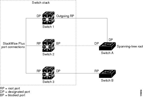
Figure 1. Spanning-tree port states in a switch stack. One stack member is elected as the stack root switch. The stack root switch contains the outgoing root port (Switch 1).

Spanning-tree port states in a switch stack

The IEEE 802.1D standard requires that each device has a unique bridge identifier (bridge ID), which controls the root switch selection. Because each VLAN is considered a different logical bridge with PVST+ and Rapid PVST+, the same device must have a different bridge ID for each configured VLAN. Each VLAN on the device has a unique 8-byte bridge ID. The 2 most-significant bytes are used for the device priority, and the remaining 6 bytes are derived from the device MAC address.

The 2 bytes that were previously allocated for device priority have been restructured into a 4-bit priority value and a 12-bit extended system ID, which represents the VLAN ID.

Table 2. Device priority value and extended system ID

Priority Value (4-bit)

Extended System ID (12-bit ) - VLAN ID

Bit 16

Bit 15

Bit 14

Bit 13

Bit 12

Bit 11

Bit 10

Bit 9

Bit 8

Bit 7

Bit 6

Bit 5

Bit 4

Bit 3

Bit 2

Bit 1

32768

16384

8192

4096

2048

1024

512

256

128

64

32

16

8

4

2

1

Spanning tree uses the extended system ID, the device priority, and the allocated spanning-tree MAC address to make the bridge ID unique for each VLAN.

Support for the extended system ID affects how you manually configure the root switch, the secondary root switch, and the switch priority of a VLAN. For example, when you change the switch priority value, you change the probability that the switch will be elected as the root switch. Configuring a higher value decreases the probability, while a lower value increases the probability.

Port priority versus path cost

Port priority versus path cost is a spanning tree selection mechanism that

  • uses port priority when selecting an interface to put into the forwarding state if a loop occurs

  • uses path cost derived from media speed of an interface as the default value for spanning tree cost calculations, and

  • applies different selection criteria for switch stack members versus standalone devices.

Port priority selection criteria

You can assign higher priority values (lower numerical values) to interfaces that you want selected first, and lower priority values (higher numerical values) that you want selected last. If all interfaces have the same priority value, spanning tree puts the interface with the lowest interface number in the forwarding state and blocks the other interfaces.

The spanning-tree path cost default value is derived from the media speed of an interface. If a loop occurs, spanning tree uses cost when selecting an interface to put in the forwarding state. You can assign lower cost values to interfaces that you want selected first, and higher cost values that you want selected last. If all interfaces have the same cost value, spanning tree puts the interface with the lowest interface number in the forwarding state and blocks the other interfaces.

If your device is a member of a switch stack, you must assign lower cost values to interfaces that you want selected first and higher cost values that you want selected last, instead of adjusting its port priority.

Spanning-tree interface states

A spanning-tree interface state is a protocol mechanism that

  • prevents temporary data loops during topology changes by controlling frame forwarding participation

  • allows proper propagation of topology information throughout the switched network, and

  • ensures frame lifetime expiration for frames using old topology before enabling forwarding.

Spanning-tree propagation delays

You may experience propagation delays when protocol information passes through a switched LAN. These delays can cause topology changes at different times and locations within your network.

If an interface transitions directly from not participating in the spanning-tree topology to the forwarding state, the network can create temporary data loops. You must wait for new topology information to propagate through the switched LAN before forwarding frames. Wait until the frame lifetime expires for any frames forwarded using the old topology.

Spanning-tree interface state types and transitions

Each Layer 2 interface on a device using spanning tree exists in one of these states:

  • Blocking: The interface does not participate in frame forwarding.

  • Listening: The first transitional state after the blocking state when the spanning tree decides that the interface should participate in frame forwarding.

  • Learning: The interface prepares to participate in frame forwarding.

  • Forwarding: The interface forwards frames.

  • Disabled: The interface is not participating in spanning tree because of a shutdown port, no link on the port, or no spanning-tree instance running on the port.

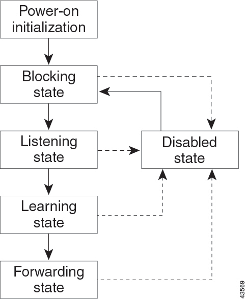
An interface moves through these states:

  • From initialization to blocking.

  • From blocking to listening or to disabled.

  • From listening to learning or to disabled.

  • From learning to forwarding or to disabled.

  • From forwarding to disabled.

This diagram illustrates the spanning-tree interface state transitions:

Figure 2. Spanning-tree interface states. An interface moves through the states.

The different states of an interface configured with spanning tree

When you power up the device, spanning tree is enabled by default, and every interface in the device, VLAN, or network goes through the blocking state and the transitory states of listening and learning. Spanning tree stabilizes each interface at the forwarding or blocking state.

When the spanning-tree algorithm places a Layer 2 interface in the forwarding state, this process occurs:

  1. The interface is in the listening state while spanning tree waits for protocol information before transitioning to the learning state.

  2. While spanning tree waits for the forward-delay timer to expire, it moves the interface to the learning state and resets the forward-delay timer.

  3. In the learning state, the interface continues to block frame forwarding as the device learns end-station location information for the forwarding database.

  4. When the forward-delay timer expires, spanning tree moves the interface to the forwarding state, where both learning and frame forwarding are enabled.

Blocking state

A blocking state is a Layer 2 interface state that

  • does not participate in frame forwarding,

  • occurs after device initialization when a BPDU is sent to each device interface, and

  • transitions through BPDU exchange to establish the root device in the network.

If your network has only one device, the system does not perform an exchange. After the forward-delay timer expires, the interface moves to the listening state.

Blocking state functions

An interface in the blocking state performs these functions:

  • Discards frames received on the interface.

  • Discards frames that are switched from another interface for forwarding.

  • Does not learn addresses.

  • Receives BPDUs.

Listening state

A listening state is a Layer 2 interface state that

  • is the first state an interface enters after the blocking state,

  • occurs when the spanning tree decides that the interface should participate in frame forwarding, and

  • processes BPDUs while discarding data frames.

Interface functions in listening state

An interface in the listening state performs these functions:

  • Discards frames received on the interface.

  • Discards frames that are switched from another interface for forwarding.

  • Does not learn addresses.

  • Receives BPDUs.

Learning state

A learning state is a Layer 2 interface state that

  • prepares to participate in frame forwarding

  • enters from the listening state, and

  • performs specific functions while transitioning to the forwarding state.

Learning state functions

An interface in the learning state performs these functions:

  • Discards frames received on the interface.

  • Discards frames that are switched from another interface for forwarding.

  • Learns addresses.

  • Receives BPDUs.

Forwarding state

A forwarding state is a Layer 2 interface state that

  • forwards frames received on the interface,

  • forwards frames switched from another interface,

  • learns addresses, and

  • receives BPDUs.

Additional interface state information

The interface enters the forwarding state from the learning state.

Disabled state

A disabled state is a Layer 2 interface state that

  • does not participate in frame forwarding or in the spanning tree

  • is nonoperational, and

  • discards all frames and does not learn addresses.

An interface in the disabled state is nonoperational.

Disabled interface functions

A disabled interface performs these functions:

  • Discards frames received on the interface.

  • Discards frames that are switched from another interface for forwarding.

  • Does not learn addresses.

  • Does not receive BPDUs.

Device or port root election process

Device or port root election is a spanning-tree process that

  • selects the root device based on the lowest device priority or MAC address when all devices have default spanning-tree settings

  • determines the root port by evaluating port priority and link characteristics to establish the optimal path, and

  • enables network administrators to force topology changes by adjusting device or port priorities to optimize traffic flow.

Root election process details

If all devices in a network are enabled with default spanning-tree settings, the device with the lowest MAC address becomes the root device.

When the spanning-tree topology is calculated based on default parameters, the path between source and destination end stations in a switched network might not be ideal. For instance, connecting higher-speed links to an interface that has a higher number than the root port can cause a root-port change. The goal is to make the fastest link the root port.

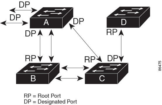
Figure 3. Spanning-tree topology. Switch A is elected as the root device because the device priority of all the devices is set to the default (32768), and Switch A has the lowest MAC address. However, due to traffic patterns, the number of forwarding interfaces, or link types, Switch A might not be the ideal root device. By increasing the priority (lowering the numerical value) of the ideal device so that it becomes the root device, you force a spanning-tree recalculation to form a new topology with the ideal device as the root.

Electing of the root device based on device priority
Root port optimization scenario

For example, assume that one port on Switch B is a Gigabit Ethernet link and that another port on Switch B (a 10/100 link) is the root port. Network traffic might be more efficient over the Gigabit Ethernet link. By changing the spanning-tree port priority on the Gigabit Ethernet port to a higher priority (lower numerical value) than the root port, the Gigabit Ethernet port becomes the new root port.

Spanning-tree address management

IEEE 802.1D specifies 17 multicast addresses, ranging from 0x00180C2000000 to 0x0180C2000010, for use by different bridge protocols. These addresses are static addresses that you cannot remove.

Regardless of the spanning-tree state, each device in the stack receives but does not forward packets destined for addresses between 0x0180C2000000 and 0x0180C200000F.

If spanning tree is enabled, the CPU on the switch or on each switch in the stack receives packets destined for 0x0180C2000000 and 0x0180C2000010. If spanning tree is disabled, the switch or each switch in the stack forwards those packets as unknown multicast addresses.

Accelerated aging to retain connectivity

Accelerated aging is a spanning tree mechanism that

  • reduces the default aging time for dynamic addresses during spanning-tree reconfiguration

  • allows station addresses to be dropped from the address table and then relearned quickly, and

  • prevents stations from being unreachable for extended periods during network topology changes.

Accelerated aging configuration details

The default aging time for dynamic addresses is 5 minutes, which is the default setting of the mac address-table aging-time global configuration command. However, a spanning-tree reconfiguration can cause many station locations to change. Because these stations could be unreachable for 5 minutes or more during a reconfiguration, the address-aging time is accelerated so that station addresses can be dropped from the address table and then relearned. The accelerated aging is the same as the forward-delay parameter value (configured with the spanning-tree VLAN VLAN-id forward-time seconds global configuration command) when the spanning tree reconfigures.

Because each VLAN is a separate spanning-tree instance, the switch accelerates aging on a per-VLAN basis. A spanning-tree reconfiguration on one VLAN can cause the dynamic addresses learned on that VLAN to be subject to accelerated aging. Dynamic addresses on other VLANs can remain unaffected and subject to the aging interval entered for the switch.

Spanning-tree modes and protocols

Provides information about the spanning-tree modes and protocols supported by your device.

Your device supports these spanning-tree modes and protocols:

  • PVST+: This spanning-tree mode is based on the IEEE 802.1D standard and Cisco proprietary extensions. PVST+ runs on each VLAN on the device up to the maximum supported, ensuring that each has a loop-free path through the network. PVST+ provides Layer 2 load-balancing for the VLAN on which it runs. You can create different logical topologies by using the VLANs on your network to ensure that all your links are used but that no one link is oversubscribed. Each instance of PVST+ on a VLAN has a single root switch. This root switch propagates the spanning-tree information associated with that VLAN to all other devices in the network. This process ensures that the network topology is maintained because each device has the same information about the network.

  • Rapid PVST+: Rapid PVST+ is the default STP mode on your device. This spanning-tree mode is the same as PVST+ except that is uses a rapid convergence based on the IEEE 802.1w standard. To provide rapid convergence, Rapid PVST+ immediately deletes dynamically learned MAC address entries on a per-port basis upon receiving a topology change. By contrast, PVST+ uses a short aging time for dynamically learned MAC address entries. Rapid PVST+ uses the same configuration as PVST+ (except where noted), and your device needs only minimal extra configuration. The benefit of Rapid PVST+ is that you can migrate a large PVST+ install base to Rapid PVST+ without having to learn the complexities of the Multiple Spanning Tree Protocol (MSTP) configuration and without having to reprovision your network. In Rapid PVST+ mode, each VLAN runs its own spanning-tree instance up to the maximum supported.

  • MSTP: This spanning-tree mode is based on the IEEE 802.1s standard. You can map multiple VLANs to the same spanning-tree instance, which reduces the number of spanning-tree instances required to support many VLANs. MSTP runs on top of the Rapid Spanning Tree Protocol (RSTP), based on IEEE 802.1w, which provides for rapid convergence of the spanning tree by eliminating the forward delay and by quickly transitioning root ports and designated ports to the forwarding state. In a switch stack, the cross-stack rapid transition (CSRT) feature performs the same function as RSTP. You cannot run MSTP without RSTP or CSRT.

Supported spanning-tree instances

The number of spanning-tree instances a device can support depend on the spanning-tree mode.

Starting with Cisco IOS XE Amsterdam 17.2.1 release, in PVST+ or Rapid PVST+ mode, your device or device stack supports up to 300 spanning-tree instances.

In MSTP mode, the device or device stack supports up to 65 MST instances. The number of VLANs that you can map to a particular MST instance is unlimited.

Spanning-tree interoperability and backward compatibility

This reference provides compatibility information for networks running different spanning-tree protocols (PVST+, MSTP, and Rapid PVST+) to help ensure proper network operation in mixed environments.

In a mixed MSTP and PVST+ network, the common spanning-tree (CST) root must be inside the MST backbone, and a PVST+ device cannot connect to multiple MST regions.

When a network contains devices running Rapid PVST+ and devices running PVST+, we recommend that you configure the Rapid PVST+ devices and PVST+ devices for different spanning-tree instances. In the Rapid PVST+ spanning-tree instances, the root switch must be a Rapid PVST+ device. In the PVST+ instances, the root switch must be a PVST+ device. The PVST+ devices should be at the edge of the network.

All stack members run the same version of spanning tree (all PVST+, all Rapid PVST+, or all MSTP).

Table 3. PVST+, MSTP, and Rapid-PVST+ interoperability and compatibility

PVST+

MSTP

Rapid PVST+

PVST+

Yes

Yes (with restrictions)

Yes (reverts to PVST+)

MSTP

Yes (with restrictions)

Yes

Yes (reverts to PVST+)

Rapid PVST+

Yes (reverts to PVST+)

Yes (reverts to PVST+)

Yes

Spanning tree protocols and IEEE 802.1Q trunks

Spanning tree protocols and IEEE 802.1Q trunks are a network configuration approach that

  • imposes limitations on spanning-tree strategy due to IEEE 802.1Q standard requirements

  • uses PVST+ to provide spanning-tree interoperability when connecting Cisco devices to non-Cisco devices, and

  • maintains one spanning-tree instance for each VLAN in Cisco device networks despite IEEE 802.1Q standard requiring only one instance for all VLANs.

Implementation details

The IEEE 802.1Q standard for VLAN trunks imposes some limitations on the spanning-tree strategy for a network. The standard requires only one spanning-tree instance for all VLANs allowed on the trunks. However, in a network of Cisco devices connected through IEEE 802.1Q trunks, the devices maintain one spanning-tree instance for each VLAN allowed on the trunks.

When you connect a Cisco device to a non-Cisco device through an IEEE 802.1Q trunk, the Cisco device uses PVST+ to provide spanning-tree interoperability. If Rapid PVST+ is enabled, the device uses it instead of PVST+. The device combines the spanning-tree instance of the IEEE 802.1Q VLAN of the trunk with the spanning-tree instance of the non-Cisco IEEE 802.1Q device.

However, all PVST+ or Rapid PVST+ information is maintained by Cisco devices that are separated by a cloud of non-Cisco IEEE 802.1Q devices. The non-Cisco IEEE 802.1Q cloud separating the Cisco devices is treated as a single trunk link between the devices.

Rapid PVST+ is automatically enabled on IEEE 802.1Q trunks, and no user configuration is required. The external spanning-tree behavior on access ports and Inter-Switch Link (ISL) trunk ports is not affected by PVST+.

Spanning tree and switch stacks

Spanning tree and switch stacks is a network configuration that

  • makes a switch stack appear as a single spanning-tree node to the rest of the network when operating in PVST+ or Rapid PVST+ mode

  • uses the same bridge ID for a given spanning tree across all stack members, derived from the MAC address of the active switch, and

  • triggers spanning-tree reconvergence when stack members join or leave the stack.

Stack membership changes

Stack membership changes affect spanning tree operations in these ways:

  • When a new device joins the stack, it sets its bridge ID to the active switch bridge ID. If the newly added device has the lowest ID and if the root path cost is the same among all stack members, the newly added device becomes the stack root.

  • When a stack member leaves the stack, spanning-tree reconvergence occurs within the stack (and possibly outside the stack). The remaining stack member with the lowest stack port ID becomes the stack root.

Active switch failure impacts spanning tree operations in this way:

  • If the switch stack is the spanning-tree root and the active switch fails or leaves the stack, the standby switch becomes the new active switch, bridge IDs remain the same, and a spanning-tree reconvergence might occur.

External device changes affect spanning tree operations in these ways:

  • If a neighboring device external to the switch stack fails or powers down, normal spanning-tree processing occurs. Spanning-tree reconvergence might occur as a result of losing a device in the active topology.

  • If a new device external to the switch stack is added to the network, normal spanning-tree processing occurs. Spanning-tree reconvergence might occur as a result of adding a device in the network.

Default spanning-tree configuration

This reference provides the default configuration settings for spanning-tree protocol features on Cisco devices.

Table 4. Default spanning-tree configuration

Feature

Default Setting

Enable state

Enabled on VLAN 1.

Spanning-tree mode

Rapid PVST+ ( PVST+ and MSTP are disabled.)

Device priority

32768

Spanning-tree port priority (configurable on a per-interface basis)

128

Spanning-tree port cost (configurable on a per-interface basis)

10 Mbps: 2000000

100 Mbps: 200000

1 Gbps: 20000

10 Gbps: 2000

40 Gbps: 500

100 Gbps: 200

1 Tbps: 20

10 Tbps: 2

Spanning-tree VLAN port priority (configurable on a per-VLAN basis)

128

Spanning-tree VLAN port cost (configurable on a per-VLAN basis)

10 Mbps: 2000000

100 Mbps: 200000

1 Gbps: 20000

10 Gbps: 2000

40 Gbps: 500

100 Gbps: 200

1 Tbps: 20

10 Tbps: 2

Spanning-tree timers

Hello time: 2 seconds

Forward-delay time: 15 seconds

Maximum-aging time: 20 seconds

Transmit hold count: 6 BPDUs

Restrictions for spanning tree protocol

Consider these restrictions when configuring spanning tree protocol.

  • Configuring a device as the root device will fail if its device priority value is set below 1.

  • If your network includes devices that support and do not support the extended system ID, it is unlikely that the device with extended system ID support will become the root device. The extended system ID increases the device priority value each time the VLAN number is greater than the priority of connected devices running older software.

  • The root device for each spanning tree instance should be a backbone or distribution device. You must not configure an access device as the spanning tree primary root.

How to configure spanning tree protocol

This reference provides the necessary configuration steps and parameters for implementing spanning tree protocol functionality on network devices.

Change the spanning-tree mode

Use this procedure to change the spanning-tree protocol from the default Rapid PVST+ to either PVST+ or MSTP on your switch.

Your switch supports three spanning-tree modes: per-VLAN spanning tree plus (PVST+), Rapid PVST+, or Multiple Spanning Tree Protocol (MSTP). By default, your device runs the Rapid PVST+ protocol.

If you want to enable a mode different from the default, use this procedure.

Procedure


Step 1

enable

Example:

Device> enable

Enables privileged EXEC mode.

Enter your password if prompted.

Step 2

configure terminal

Example:

Device# configure terminal

Enters global configuration mode.

Step 3

spanning-tree mode {PVST | mst | rapid-PVST}

Example:

Device(config)# spanning-tree mode pvst

Configures a spanning-tree mode.

All stack members run the same version of spanning tree.

  • Select PVST to enable PVST+.

  • Select mst to enable MSTP.

  • Select rapid-PVST to enable rapid PVST+.

Step 4

interface interface-ID

Example:

Device(config)# interface GigabitEthernet1/0/1

Specifies an interface to configure, and enters interface configuration mode. Valid interfaces include physical ports, VLANs, and port channels. The VLAN ID range is 1 to 4094. The port-channel range is 1 to .

Step 5

spanning-tree link-type point-to-point

Example:

Device(config-if)# spanning-tree link-type point-to-point

Specifies that the link type for this port is point-to-point.

If you connect this port (local port) to a remote port through a point-to-point link and the local port becomes a designated port, the device negotiates with the remote port and rapidly changes the local port to the forwarding state.

Step 6

end

Example:

Device(config-if)# end

Returns to privileged EXEC mode.

Step 7

clear spanning-tree detected-protocols

Example:

Device# clear spanning-tree detected-protocols

If any port on the device is connected to a port on a legacy IEEE 802.1D device, this command restarts the protocol migration process on the entire device.

This step is optional if the designated device detects that this device is running rapid PVST+.


The spanning-tree mode is configured on your switch. The new protocol settings take effect immediately.

(Optional) Disable spanning tree

Disable spanning tree protocol on specific VLANs when you are certain that no network loops exist in your topology.

Spanning tree is enabled by default on VLAN 1 and on all newly created VLANs up to the spanning-tree limit. Disable spanning tree only if you are sure that there are no loops in the network topology.


Caution


When spanning tree is disabled and loops are present in the topology, excessive traffic and indefinite packet duplication can drastically reduce network performance.


Procedure


Step 1

enable

Example:

Device> enable

Enables privileged EXEC mode.

Enter your password if prompted.

Step 2

configure terminal

Example:

Device# configure terminal

Enters global configuration mode.

Step 3

no spanning-tree VLAN VLAN-id

Example:

Device(config)# no spanning-tree vlan 300

For VLAN-id , the range is 1 to 4094.

Step 4

end

Example:

Device(config)# end

Returns to privileged EXEC mode.


Spanning tree protocol is disabled on the specified VLAN. The device no longer participates in spanning tree calculations for that VLAN.

Configure the root device

Configure a device as the root for the specified VLAN by modifying the device priority from the default value to a significantly lower value, enabling optimal STP topology control.

To configure a device as the root for the specified VLAN, use the spanning-tree VLAN VLAN-ID root global configuration command to modify the device priority from the default value (32768) to a significantly lower value. When you enter this command, the software checks the switch priority of the root switches for each VLAN. Because of the extended system ID support, the switch sets its own priority for the specified VLAN to 24576 if this value causes this switch to become the root for the specified VLAN.

You can use the diameter keyword to specify the Layer 2 network diameter. This is the maximum number of device hops between any two end stations in the Layer 2 network. When you specify the network diameter, the device automatically sets an optimal hello time, forward-delay time, and maximum-age time for a network of that diameter, which can significantly reduce the convergence time. You can use the hello keyword to override the automatically calculated hello time.

Follow these steps to configure the root device:

Procedure


Step 1

enable

Example:

Device> enable

Enables privileged EXEC mode.

Enter your password if prompted.

Step 2

configure terminal

Example:

Device# configure terminal

Enters global configuration mode.

Step 3

spanning-tree VLAN VLAN-ID root primary [diameter net-diameter ]

Example:

Device(config)# spanning-tree vlan 20-24 root primary diameter 4

Configures a device to become the root for the specified VLAN.

  • For VLAN-ID , you can specify a single VLAN identified by VLAN ID number, a range of VLANs separated by a hyphen, or a series of VLANs separated by a comma. The range is 1 to 4094.

  • (Optional) For diameter net-diameter , specify the maximum number of devices between any two end stations. The range is 2 to 7.

Step 4

end

Example:

Device(config)# end

Returns to privileged EXEC mode.


The device is configured as the root for the specified VLAN with optimized STP timing parameters based on the network diameter.

What to do next

After configuring the switch as the root switch, we recommend that you avoid manually configuring the hello time, forward-delay time, and maximum-age time through the spanning-tree VLAN VLAN-ID hello-time , spanning-tree VLAN VLAN-ID forward-time , and the spanning-tree VLAN VLAN-ID max-age global configuration commands.

Configure a secondary root device

Configure a switch as the secondary root device to ensure network continuity if the primary root switch fails. The secondary root device has a higher priority than other switches in the network, making it the next likely candidate to become the root switch.

When you configure a switch as the secondary root, the switch priority is modified from the default value (32768) to 28672. With this priority, the switch is likely to become the root switch for the specified VLAN if the primary root switch fails. This assumes that other network switches use the default switch priority of 32768, and therefore, are unlikely to become the root switch.

You can execute this command on more than one switch to configure multiple backup root switches. You must use the same network diameter and hello-time values that you used when you configured the primary root switch with the spanning-tree VLAN VLAN-ID root primary global configuration command.

Follow these steps to configure a secondary root device:

Procedure


Step 1

enable

Example:

Device> enable

Enables privileged EXEC mode.

Enter your password if prompted.

Step 2

configure terminal

Example:

Device# configure terminal

Enters global configuration mode.

Step 3

spanning-tree VLAN VLAN-ID root secondary [diameter net-diameter ]

Example:

Device(config)# spanning-tree vlan 20-24 root secondary diameter 4

Configures a device to become the secondary root for the specified VLAN.

  • For VLAN-ID , you can specify a single VLAN identified by VLAN ID number, a range of VLANs separated by a hyphen, or a series of VLANs separated by a comma. The range is 1 to 4094.

  • (Optional) For diameter net-diameter , specify the maximum number of devices between any two end stations. The range is 2 to 7.

Use the same network diameter value that you used when configuring the primary root switch.

Step 4

end

Example:

Device(config)# end

Returns to privileged EXEC mode.


The device is configured as a secondary root for the specified VLANs with priority 28672. If the primary root switch fails, this device will likely become the root switch for the configured VLANs.

Configure port priority

Configure port priority to control which ports are selected as forwarding ports in the STP topology. Lower priority values increase the likelihood that a port will be selected as a forwarding port.

Port priority determines which ports become forwarding ports when there are redundant links in the network topology. This configuration is optional and should be used when you need to influence STP path selection.

Before you begin

Follow these steps to configure port priority:

Procedure


Step 1

enable

Example:

Device> enable

Enables privileged EXEC mode.

Enter your password if prompted.

Step 2

configure terminal

Example:

Device# configure terminal

Enters global configuration mode.

Step 3

interface interface-ID

Example:

Device(config)# interface gigabitethernet 1/0/2

Specifies an interface to configure, and enters interface configuration mode.

Valid interfaces include physical ports and port-channel logical interfaces (port-channel port-channel-number ).

Step 4

spanning-tree port-priority priority

Example:

Device(config-if)# spanning-tree port-priority 0

Configures the port priority for an interface.

For priority , the range is 0 to 240, in increments of 16; the default is 128. Valid values are 0, 16, 32, 48, 64, 80, 96, 112, 128, 144, 160, 176, 192, 208, 224, and 240. All other values are rejected. The lower the number, the higher the priority.

Step 5

spanning-tree VLAN VLAN-ID port-priority priority

Example:

Device(config-if)# spanning-tree vlan 20-25 port-priority 0

Configures the port priority for a VLAN.

  • For VLAN-ID , you can specify a single VLAN identified by VLAN ID number, a range of VLANs separated by a hyphen, or a series of VLANs separated by a comma. The range is 1 to 4094.

  • For priority , the range is 0 to 240, in increments of 16; the default is 128. Valid values are 0, 16, 32, 48, 64, 80, 96, 112, 128, 144, 160, 176, 192, 208, 224, and 240. All other values are rejected. The lower the number, the higher the priority.

Step 6

end

Example:

Device(config-if)# end

Returns to privileged EXEC mode.


The port priority configuration is applied to the specified interface. The device will use the configured priority values when calculating the STP topology and determining which ports should be in the forwarding state.

Configure path cost

Configure path cost values to influence spanning tree protocol path selection when loops occur in the network topology.

Path cost configuration allows you to control which interfaces spanning tree selects for forwarding when multiple paths exist. Lower path costs represent higher-speed transmission links and are preferred for forwarding traffic.

Before you begin

Ensure you have administrative access to the device and understand your network topology before modifying path costs.

Follow these steps to configure path cost:

Procedure


Step 1

enable

Example:

Device> enable

Enables privileged EXEC mode.

Enter your password if prompted.

Step 2

configure terminal

Example:

Device# configure terminal

Enters global configuration mode.

Step 3

interface interface-ID

Example:

Device(config)# interface gigabitethernet 1/0/1

Specifies an interface to configure, and enters interface configuration mode. Valid interfaces include physical ports and port-channel logical interfaces (port-channel port-channel-number ).

Step 4

spanning-tree cost cost

Example:

Device(config-if)# spanning-tree cost 250

Configures the cost for an interface.

If a loop occurs, spanning tree uses the path cost when selecting an interface to place into the forwarding state. A lower path cost represents higher-speed transmission.

For cost , the range is 1 to 200000000; the default value is derived from the media speed of the interface.

Step 5

spanning-tree VLAN VLAN-ID cost cost

Example:

Device(config-if)# spanning-tree vlan 10,12-15,20 cost 300

Configures the cost for a VLAN.

If a loop occurs, spanning tree uses the path cost when selecting an interface to place into the forwarding state. A lower path cost represents higher-speed transmission.

  • For VLAN-ID , you can specify a single VLAN identified by VLAN ID number, a range of VLANs separated by a hyphen, or a series of VLANs separated by a comma. The range is 1 to 4094.

  • For cost , the range is 1 to 200000000; the default value is derived from the media speed of the interface.

Step 6

end

Example:

Device(config-if)# end

Returns to privileged EXEC mode.


The show spanning-tree interface interface-ID privileged EXEC command displays information only for ports that are in a link-up operative state. Otherwise, you can use the show running-config privileged EXEC command to confirm the configuration.

(Optional) configure the device priority of a VLAN

Configure the switch priority to make it more likely that a standalone switch or a switch in the stack will be chosen as the root switch.

You can configure the switch priority to make it more likely that a standalone switch or a switch in the stack will be chosen as the root switch.


Note


Exercise care when using this command. For most situations, we recommend that you use the spanning-tree VLAN VLAN-ID root primary and the spanning-tree VLAN VLAN-ID root secondary global configuration commands to modify the switch priority.


Procedure


Step 1

enable

Example:

Device> enable

Enables privileged EXEC mode.

Enter your password if prompted.

Step 2

configure terminal

Example:

Device# configure terminal

Enters global configuration mode.

Step 3

spanning-tree VLAN VLAN-ID priority priority

Example:

Device(config)# spanning-tree vlan 20 priority 8192

Configures the device priority of a VLAN.

  • For VLAN-ID , you can specify a single VLAN identified by VLAN ID number, a range of VLANs separated by a hyphen, or a series of VLANs separated by a comma. The range is 1 to 4094.

  • For priority , the range is 0 to 61440 in increments of 4096; the default is 32768. The lower the number, the more likely the switch will be chosen as the root switch.

    Valid priority values are 4096, 8192, 12288, 16384, 20480, 24576, 28672, 32768, 36864, 40960, 45056, 49152, 53248, 57344, and 61440. All other values are rejected.

Step 4

end

Example:

Device(config-if)# end

Returns to privileged EXEC mode.


The device priority for the specified VLAN is configured, affecting the spanning tree root switch selection process.

(Optional) configure the hello time

Configure the hello time to control the time interval between configuration messages that the root switch generates and sends.

The hello time is the time interval between configuration messages that the root switch generates and sends.

Before you begin

Follow these steps to configure the hello time:

Procedure


Step 1

enable

Example:

Device> enable

Enables privileged EXEC mode.

Enter your password if prompted.

Step 2

spanning-tree VLAN VLAN-ID hello-time seconds

Example:

Device(config)# spanning-tree vlan 20-24 hello-time 3

Configures the hello time of a VLAN. The hello time is the time interval between configuration messages that are generated and sent by the root switch. These messages mean that the switch is alive.

  • For VLAN-ID , you can specify a single VLAN identified by VLAN ID number, a range of VLANs separated by a hyphen, or a series of VLANs separated by a comma. The range is 1 to 4094.

  • For seconds , the range is 1 to 10; the default is 2.

Step 3

end

Example:

Device(config-if)# end

Returns to privileged EXEC mode.


The hello time is configured for the specified VLAN. The switch will generate and send configuration messages at the configured time interval.

(Optional) configure the forwarding-delay time for a VLAN

Configure the forwarding-delay time for a specific VLAN to control how long an interface waits before changing from its spanning-tree learning and listening states to the forwarding state.

The forwarding delay determines the number of seconds an interface waits before transitioning from the spanning-tree learning and listening states to the forwarding state.

Before you begin

Follow these steps to configure the forwarding-delay time for a VLAN:

Procedure


Step 1

enable

Example:

Device> enable

Enables privileged EXEC mode.

Enter your password if prompted.

Step 2

configure terminal

Example:

Device# configure terminal

Enters global configuration mode.

Step 3

spanning-tree VLAN VLAN-ID forward-time seconds

Example:

Device(config)# spanning-tree vlan 20,25 forward-time 18

Configures the forward time of a VLAN. The forwarding delay is the number of seconds an interface waits before changing from its spanning-tree learning and listening states to the forwarding state.

  • For VLAN-ID , you can specify a single VLAN identified by VLAN ID number, a range of VLANs separated by a hyphen, or a series of VLANs separated by a comma. The range is 1 to 4094.

  • For seconds , the range is 4 to 30; the default is 15.

Step 4

end

Example:

Device(config)# end

Returns to privileged EXEC mode.


The forwarding-delay time is configured for the specified VLAN. The interface will now wait for the configured number of seconds before transitioning from the learning and listening states to the forwarding state.

Configure the maximum-aging time for a VLAN

Configure the maximum-aging time for a VLAN to control spanning-tree reconfiguration timing and improve network stability.

The maximum-aging time determines how long a switch waits without receiving spanning-tree configuration messages before attempting a reconfiguration.

Procedure


Step 1

enable

Example:

Device> enable

Enables privileged EXEC mode.

Enter your password if prompted.

Step 2

configure terminal

Example:

Device# configure terminal

Enters global configuration mode.

Step 3

spanning-tree VLAN VLAN-ID max-age seconds

Example:

Device(config)# spanning-tree vlan 20 max-age 30

Configures the maximum-aging time of a VLAN. The maximum-aging time is the number of seconds a switch waits without receiving spanning-tree configuration messages before attempting a reconfiguration.

  • For VLAN-ID , you can specify a single VLAN identified by VLAN ID number, a range of VLANs separated by a hyphen, or a series of VLANs separated by a comma. The range is 1 to 4094.

  • For seconds , the range is 6 to 40; the default is 20.

Step 4

end

Example:

Device(config-if)# end

Returns to privileged EXEC mode.


The maximum-aging time for the specified VLAN is configured. The switch will now wait for the configured number of seconds without receiving spanning-tree configuration messages before attempting a reconfiguration.

Configure the transmit hold-count

Configure the Bridge Protocol Data Unit (BPDU) burst size by changing the transmit hold count value.

You can configure the Bridge Protocol Data Unit (BPDU) burst size by changing the transmit hold count value.


Note


Changing this parameter to a higher value significantly impact CPU utilization, especially in Rapid PVST+ mode. Lowering this value can slow down convergence in certain scenarios. We recommend that you maintain the default setting.


Before you begin

Follow these steps to configure the transmit hold-count:

Procedure


Step 1

enable

Example:

Device> enable

Enables privileged EXEC mode.

Enter your password if prompted.

Step 2

configure terminal

Example:

Device# configure terminal

Enters global configuration mode.

Step 3

spanning-tree transmit hold-count value

Example:

Device(config)# spanning-tree transmit hold-count 6

Configures the number of BPDUs that can be sent before pausing for 1 second.

For value , the range is 1 to 20; the default is 6.

Step 4

end

Example:

Device(config)# end

Returns to privileged EXEC mode.


The transmit hold-count is configured with the specified value for BPDU burst size management.

Monitor spanning tree protocol configuration status

This reference provides commands to monitor the configuration status of spanning tree protocol (STP) on network interfaces and VLANs.

Table 5. Commands for displaying STP configuration status

Command

Description

show spanning-tree active

Displays STP configuration information on active interfaces only.

show spanning-tree detail

Displays a detailed summary of interface information.

show spanning-tree VLAN VLAN-id

Displays STP configuration information for the specified VLAN.

show spanning-tree interface interface-id

Displays STP configuration information for the specified interface.

show spanning-tree interface interface-id portfast

Displays STP portfast information for the specified interface.

show spanning-tree summary [totals]

Displays a summary of interface states or displays the total lines of the STP state section.

To clear STP counters, use the clear spanning-tree [interface interface-id] privileged EXEC command.