EtherChannel

Feature History for EtherChannels

This table provides release and related information for features explained in this module.

These features are available on all releases subsequent to the one they were introduced in, unless noted otherwise.

Release

Feature

Feature Information

Cisco IOS XE 17.18.1

EtherChannels: EtherChannel provides fault-tolerant high-speed links between switches, routers, and servers.

Cisco C9350 Series Smart Switches

Cisco C9610 Series Smart Switches

Use Cisco Feature Navigator to find information about platform and software image support. To access Cisco Feature Navigator, go to http://www.cisco.com/go/cfn .
Restrictions for EtherChannels

EtherChannel configuration restrictions

Consider these restrictions when configuring EtherChannels:

  • All ports in an EtherChannel must be assigned to the same VLAN or they must be configured as trunk port.

  • The LACP 1:1 redundancy feature is supported on port channel interfaces only.

Unsupported EtherChannel features

The following features are not supported with EtherChannels:

  • You cannot configure a voice VLAN on a port channel or a member interface.

  • You cannot convert an interface to an ether channel if dot1ad is configured on the interface.

  • You cannot configure nonegotiate and dynamic commands on a port channel.

  • You cannot configure pruning VLAN if MVRP feature is already configured on the device.

  • You cannot configure network policy commands on a routed or trunk port and on an ether channel.

  • You can configure the rep segment command only on switch port mode trunk.

  • You cannot configure switchport priority extend trust command and switchport priorit extend cos 3 command on an etherchannel.

  • You cannot configure platform qos low-latency command on an interface port-channel 10.

  • You cannot use Layer 2 configurations on a Layer 3 port.

  • When there are any misconfigurations detected in a port mode or VLAN mask, the ports are suspended.

  • On EtherChannel member port selection is software based in Layer 2 and Layer 3 multicast route. This means that all multicast traffic under a group will be routed via the same physical port of the EtherChannel. As a result, the distribution of multicast traffic load balance over etherchannels might not evenly spread across member ports.

Information about EtherChannels

This sections provide information about EtherChannels and the various modes to configure EtherChannels.

EtherChannel

An EtherChannel is a network technology that

  • consists of individual Ethernet links that are bundled into a single logical link

  • provides fault-tolerant high-speed links between switches, routers, and servers

  • can consist of up to eight compatibly configured Ethernet ports.

EtherChannel capabilities

EtherChannel provides these capabilities:

  • Increases the bandwidth between the wiring closets and the data center

  • Can be deployed anywhere in the network where bottlenecks are likely to occur

  • Provides automatic recovery for the loss of a link by redistributing the load across the remaining links

  • Redirects traffic from the failed link to the remaining links in the channel without intervention when a link fails

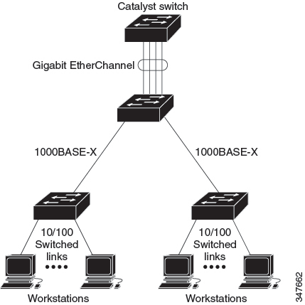
Figure 1. Typical EtherChannel configuration
Typical EtherChannel Configuration

Channel groups and port-channel interfaces

An EtherChannel is a network aggregation technology that

  • comprises a channel group and a port-channel interface

  • binds physical ports to the port-channel interface through the channel group, and

  • applies configuration changes from the port-channel interface to all physical ports in the channel group.

EtherChannel configuration requirements

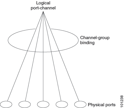
Figure 2. Relationship between physical ports, a channel group, and a Port-Channel interface
Relationship of Physical Ports, Logical Port Channels, and Channel Groups

The channel-group command binds the physical port and the port-channel interface together. Each EtherChannel has a port-channel logical interface numbered from 1 to. This port-channel interface number corresponds to the one specified with the channel-group interface configuration command.

  • With Layer 2 ports, use the channel-group interface configuration command to dynamically create the port-channel interface.

    You also can use the interface port-channel port-channel-number global configuration command to manually create the port-channel interface, but then you must use the channel-group channel-group-number command to bind the logical interface to a physical port. The channel-group-number can be the same as the port-channel-number, or you can use a new number. If you use a new number, the channel-group command dynamically creates a new port channel.

  • With Layer 3 ports, you should manually create the logical interface by using the interface port-channel global configuration command followed by the no switchport interface configuration command. You then manually assign an interface to the EtherChannel by using the channel-group interface configuration command.

Port Aggregation Protocol

The Port Aggregation Protocol (PAgP) is a Cisco-proprietary protocol that can be run only on Cisco devices and on those devices that are licensed by vendors to support PAgP. PAgP facilitates the automatic creation of EtherChannels by exchanging PAgP packets between Ethernet ports.

By using PAgP, the switch or switch stack learns the identity of partners capable of supporting PAgP and the capabilities of each port. It then dynamically groups similarly configured ports (on a single device in the stack) into a single logical link (channel or aggregate port). Similarly configured ports are grouped based on hardware, administrative, and port parameter constraints. For example, PAgP groups the ports with the same speed, duplex mode, native VLAN, VLAN range, and trunking status and type. After grouping the links into an EtherChannel, PAgP adds the group to the spanning tree as a single device port.

Port Aggregation Protocol Modes

PAgP modes specify whether a port can send PAgP packets, which start PAgP negotiations, or only respond to PAgP packets received.

Table 1. EtherChannel PAgP Modes

Mode

Description

auto

Places a port into a passive negotiating state, in which the port responds to PAgP packets it receives but does not start PAgP packet negotiation. This setting minimizes the transmission of PAgP packets.

desirable

Places a port into an active negotiating state, in which the port starts negotiations with other ports by sending PAgP packets.

Switch ports exchange PAgP packets only with partner ports that are configured in the auto or desirable modes. Ports that are configured in the on mode do not exchange PAgP packets.

Both the auto and desirable modes enable ports to negotiate with partner ports to form an EtherChannel based on criteria such as port speed. and for Layer 2 EtherChannels, based on trunk state and VLAN numbers.

Ports can form an EtherChannel when they are in different PAgP modes as long as the modes are compatible. For example:

Table 2. PAgP Mode Compatibility and Interaction

Mode

Description

auto

A port in the auto mode can form an EtherChannel with another port in the desirable mode.

A port in the auto mode cannot form an EtherChannel with another port that is also in the auto mode because neither port starts PAgP negotiation.

desirable

A port in the desirable mode can form an EtherChannel with another port that is in the desirable or auto mode.

Silent mode

If your switch is connected to a partner that is PAgP-capable, you can configure the switch port for nonsilent operation by using the non-silent keyword. If you do not specify non-silent with the auto or desirable mode, silent mode is assumed.

Use the silent mode when the switch is connected to a device that is not PAgP-capable and seldom, if ever, sends packets. An example of a silent partner is a file server or a packet analyzer that is not generating traffic. In this case, running PAgP on a physical port that is connected to a silent partner prevents that switch port from ever becoming operational. However, the silent setting allows PAgP to operate, to attach the port to a channel group, and to use the port for transmission.

Port aggregation protocol learn method and priority

Port aggregation protocol learn method and priority is a PAgP configuration mechanism that

  • classifies network devices as either physical learners or aggregate-port learners based on how they learn MAC addresses

  • requires identical learn method configuration at both ends of the link for proper operation, and

  • enables priority-based port selection within EtherChannel groups for transmission optimization.

PAgP learning methods

Network devices are classified as PAgP physical learners or aggregate-port learners. A device is a physical learner if it learns addresses by physical ports and directs transmissions based on that knowledge. A device is an aggregate-port learner if it learns addresses by aggregate (logical) ports. The learn method must be configured the same at both ends of the link.

When a device and its partner are both aggregate-port learners, they learn the address on the logical port-channel. The device sends packets to the source by using any of the ports in the EtherChannel. With aggregate-port learning, it is not important on which physical port the packet arrives.

PAgP cannot automatically detect when the partner device is a physical learner and when the local device is an aggregate-port learner. Therefore, you must manually set the learning method on the local device to learn addresses by physical ports. You also must set the load-distribution method to source-based distribution, so that any given source MAC address is always sent on the same physical port.

You also can configure a single port within the group for all transmissions and use other ports for hot-standby. The unused ports in the group can be swapped into operation in just a few seconds if the selected single port loses hardware-signal detection. You can configure which port is always selected for packet transmission by changing its priority with the pagp port-priority interface configuration command. The higher the priority, the more likely that the port will be selected.


Note


The device supports address learning only on aggregate ports even though the physical-port keyword is provided in the CLI. The pagp learn-method command and the pagp port-priority command have no effect on the device hardware, but they are required for PAgP interoperability with devices that only support address learning by physical ports, such as the Catalyst 1900 switch.

When the link partner of the device is a physical learner, we recommend that you configure the device as a physical-port learner by using the pagp learn-method physical-port interface configuration command. Set the load-distribution method based on the source MAC address by using the port-channel load-balance src-MAC global configuration command. The device then sends packets to the physical learner using the same port in the EtherChannel from which it learned the source address. Only use the pagp learn-method command in this situation.


Port aggregation protocol interaction with other features

Port Aggregation Protocol interaction with other features is a set of operational behaviors that

  • enables Dynamic Trunking Protocol (DTP) and Cisco Discovery Protocol (CDP) to send and receive packets over physical ports in the EtherChannel

  • allows trunk ports to send and receive PAgP protocol data units (PDUs) on the lowest numbered VLAN, and

  • manages MAC address allocation for both Layer 2 and Layer 3 EtherChannels.

Protocol behavior details

In Layer 2 EtherChannels, the first port in the channel that comes up provides its MAC address to the EtherChannel. If this port is removed from the bundle, one of the remaining ports in the bundle provides its MAC address to the EtherChannel. For Layer 3 EtherChannels, the MAC address is allocated by the active device as soon as the interface is created (through the interface port-channel global configuration command).

PAgP sends and receives PAgP PDUs only from ports that are up and have PAgP enabled for the auto or desirable mode.

EtherChannel on mode

EtherChannel on mode is a manual configuration method that

  • forces a port to join an EtherChannel without negotiations

  • is useful if the remote device does not support PAgP or LACP, and

  • creates a usable EtherChannel only when devices at both ends of the link are configured in the on mode.

Port configuration requirements

Ports that are configured in the on mode in the same channel group must have compatible port characteristics, such as speed and duplex. Ports that are not compatible are suspended, even though they are configured in the on mode.


Caution


You should use care when using the on mode. This is a manual configuration, and ports on both ends of the EtherChannel must have the same configuration. If the group is misconfigured, packet loss or spanning-tree loops can occur.


Load-balancing and forwarding methods

Load-balancing and forwarding methods are EtherChannel traffic distribution mechanisms that

  • balance traffic load across links in a channel by reducing part of the binary pattern formed from frame addresses to a numerical value

  • select one of the links in the channel based on configurable parameters including MAC addresses, IP addresses, VLAN IDs, source addresses, destination addresses, or both source and destination addresses, and

  • apply the selected mode to all EtherChannels configured on the device.

Load-balancing configuration details

Platform-specific load-balancing features include these capabilities:


Note


Layer 3 Equal-cost multi path (ECMP) load balancing is based on source IP address, destination IP address, source port, destination port, and layer 4 protocol. Fragmented packets will be treated on two different links based on the algorithm that is calculated using these parameters. Any changes in one of these parameters result in load balancing.


MAC address forwarding

MAC address forwarding is a load-balancing method that

  • distributes packets across EtherChannel ports based on MAC address information

  • uses source MAC address, destination MAC address, or both addresses to determine port selection, and

  • ensures consistent packet forwarding behavior for the same host or destination pair.

MAC address forwarding methods

MAC address forwarding includes three primary methods:

  • Source-MAC address forwarding: When packets are forwarded to an EtherChannel, they are distributed across the ports in the channel based on the source-MAC address of the incoming packet. Therefore, to provide load-balancing, packets from different hosts use different ports in the channel, but packets from the same host use the same port in the channel.

  • Destination-MAC address forwarding: When packets are forwarded to an EtherChannel, they are distributed across the ports in the channel based on the destination host's MAC address of the incoming packet. Therefore, packets to the same destination are forwarded over the same port, and packets to a different destination are sent on a different port in the channel.

  • Source-and-destination MAC address forwarding: When packets are forwarded to an EtherChannel, they are distributed across the ports in the channel based on both the source and destination MAC addresses. This forwarding method, a combination source-MAC and destination-MAC address forwarding methods of load distribution, can be used if it is not clear whether source-MAC or destination-MAC address forwarding is better suited on a particular device. With source-and-destination MAC-address forwarding, packets sent from host A to host B, host A to host C, and host C to host B could all use different ports in the channel.

IP address forwarding

IP address forwarding is a load balancing mechanism that

  • distributes packets across ports in an EtherChannel based on IP addresses of incoming packets

  • provides different distribution methods including source-IP, destination-IP, or source-and-destination IP address-based forwarding, and

  • ensures consistent port selection for packets with the same IP address characteristics.

IP address forwarding methods

There are three types of IP address forwarding methods:

  • Source-IP address-based forwarding: Packets are distributed across the ports in the EtherChannel based on the source-IP address of the incoming packet. To provide load balancing, packets from different IP addresses use different ports in the channel, and packets from the same IP address use the same port in the channel.

  • Destination-IP address-based forwarding: Packets are distributed across the ports in the EtherChannel based on the destination-IP address of the incoming packet. To provide load balancing, packets from the same IP source address that is sent to different IP destination addresses could be sent on different ports in the channel. Packets sent from different source IP addresses to the same destination IP address are always sent on the same port in the channel.

  • Source-and-destination IP address-based forwarding: Packets are distributed across the ports in the EtherChannel based on both the source and destination IP addresses of the incoming packet. This forwarding method, a combination of source-IP and destination-IP address-based forwarding, can be used if it is not clear whether source-IP or destination-IP address-based forwarding is better suited on a particular device. In this method, packets sent from the IP address A to IP address B, from IP address A to IP address C, and from IP address C to IP address B could all use different ports in the channel.

Load-balancing advantages

A load-balancing advantage is a network benefit that

  • varies depending on the specific load-balancing method chosen

  • depends on the device's position in the network topology, and

  • is optimized based on the type of traffic that needs to be distributed.

Selection criteria

The choice of a particular load-balancing method should be based on the position of the device in the network and the kind of traffic that needs to be load-distributed.

Use the option that provides the greatest variety in your configuration. For example, if the traffic on a channel is going only to a single MAC address, using the destination-MAC address always chooses the same link in the channel. Using source addresses or IP addresses might result in better load-balancing.

Load distribution and forwarding methods

This example shows how different load-balancing methods optimize traffic distribution in an EtherChannel configuration.

Figure 3. Load distribution and forwarding methods. In the following figure, an EtherChannel of four workstations communicates with a router. Because the router is a single MAC-address device, source-based forwarding on the switch EtherChannel ensures that the switch uses all available bandwidth to the router. The router is configured for destination-based forwarding because the large number of workstations ensures that the traffic is evenly distributed from the router EtherChannel.

Load Distribution and Forwarding Methods

EtherChannel and switch stacks

EtherChannel and switch stacks is a networking configuration that

  • maintains connectivity when stack member failures occur by removing failed ports from the channel

  • automatically updates new stack members with EtherChannel configuration and operational information, and

  • handles self-looped ports through spanning tree detection during stack merges.

Stack member failure behavior

If a stack member that has ports participating in an EtherChannel fails or leaves the stack, the active switch removes the failed stack member switch ports from the EtherChannel. The remaining ports of the EtherChannel, if any, continue to provide connectivity.

When a switch is added to an existing stack, the new switch receives the running configuration from the active switch and updates itself with the EtherChannel-related stack configuration. The stack member also receives the operational information (the list of ports that are up and are members of a channel).

When two stacks merge that have EtherChannels configured between them, self-looped ports result. Spanning tree detects this condition and acts accordingly. Any PAgP or LACP configuration on a winning switch stack is not affected, but the PAgP or LACP configuration on the losing switch stack is lost after the stack reboots.

Switch stack and port aggregation protocol

Switch Stack and Port Aggregation Protocol is a network configuration that enables automatic failover management between active and standby switches while maintaining EtherChannel configurations through PAgP synchronization.

PAgP failover behavior

With PAgP, if the active switch fails or leaves the stack, the standby switch becomes the new active switch. The new active switch synchronizes the configuration of the stack members to that of the active switch. The PAgP configuration is not affected after an active switch change unless the EtherChannel has ports residing on the old active switch.

Switch stacks and link aggregation control protocol

Switch stacks with LACP is a network configuration that uses the system ID from the active switch stack MAC address, maintains LACP system ID consistency when the active switch changes, and preserves default LACP configuration during active switch transitions.

LACP behavior in switch stacks

With LACP, the system ID uses the stack MAC address from the active switch. When an active switch fails or leaves the stack and the standby switch becomes the new active switch, the LACP system ID is unchanged. By default, the LACP configuration is not affected after the active switch changes.

Default EtherChannel configuration

This reference provides the default EtherChannel configuration settings for features such as channel groups, port-channel logical interfaces, PAgP and LACP modes, priorities, learn methods, system settings, and load-balancing options.

The default EtherChannel configuration is described in this table.

Table 4. Default EtherChannel configuration

Feature

Default Setting

Channel groups

None assigned.

Port-channel logical interface

None defined.

PAgP mode

No default.

PAgP learn method

Aggregate-port learning on all ports.

PAgP priority

128 on all ports.

LACP mode

No default.

LACP learn method

Aggregate-port learning on all ports.

LACP port priority

32768 on all ports.

LACP system priority

32768.

LACP system ID

LACP system priority and the switch or stack MAC address.

Load-balancing

Load distribution on the switch is based on the source-MAC address of the incoming packet.

Best practice for EtherChannel configuration

If improperly configured, some EtherChannel ports are automatically disabled to avoid network loops and other problems. Follow these guidelines to avoid configuration problems:

  • Configure all ports in an EtherChannel to operate at the same speeds and duplex modes.

  • Enable all ports in an EtherChannel. A port in an EtherChannel that is disabled by using the shutdown interface configuration command is treated as a link failure, and its traffic is transferred to one of the remaining ports in the EtherChannel.

  • When a group is first created, all ports follow the parameters set for the first port to be added to the group. If you change the configuration of one of these parameters, you must also make the changes to all ports in the group:

    • Allowed-VLAN list

    • Spanning-tree path cost for each VLAN

    • Spanning-tree port priority for each VLAN

    • Spanning-tree Port Fast setting

  • Do not configure a port to be a member of more than one EtherChannel group.

  • Do not configure an EtherChannel in both the PAgP and LACP modes. EtherChannel groups running PAgP and LACP can coexist on the same switch or on different switches in the stack. Individual EtherChannel groups can run either PAgP or LACP, but they cannot interoperate.

  • Do not configure a port that is an active or a not-yet-active member of an EtherChannel as an IEEE 802.1x port. If you try to enable IEEE 802.1x on an EtherChannel port, an error message appears, and IEEE 802.1x is not enabled.

  • If EtherChannels are configured on device interfaces, remove the EtherChannel configuration from the interfaces before globally enabling IEEE 802.1x on a device by using the dot1x system-auth-control global configuration command.

Guidelines for layer 2 EtherChannel configuration

When configuring Layer 2 EtherChannels, follow these guidelines:

  • Assign all ports in the EtherChannel to the same VLAN, or configure them as trunks. Ports with different native VLANs cannot form an EtherChannel.

  • An EtherChannel supports the same allowed range of VLANs on all the ports in a trunking Layer 2 EtherChannel. If the allowed range of VLANs is not the same, the ports do not form an EtherChannel even when PAgP is set to the auto or desirable mode.

  • Ports with different spanning-tree path costs can form an EtherChannel if they are otherwise compatibly configured. Setting different spanning-tree path costs does not, by itself, make ports incompatible for the formation of an EtherChannel.

Recommendation: assign layer 3 address to port-channel logical interface

For Layer 3 EtherChannels, assign the Layer 3 address to the port-channel logical interface, not to the physical ports in the channel.

Auto-LAG

Auto-LAG feature:

  • Automatically creates EtherChannels on ports connected to a switch.

  • Uses the LACP (Link Aggregation Control Protocol) to create auto EtherChannels.

  • Supports only one EtherChannel per unique partner device.

  • Disabled globally by default, but is enabled on all port interfaces.

  • Requires global enablement for Auto-LAG to operate. Ports must also meet specific conditions:

    • Ports with existing manual EtherChannels cannot participate in auto EtherChannel creation.

    • Disabling Auto-LAG on a port causes it to unbundle from any auto-created EtherChannel.

  • Global disablement results in all existing auto-created EtherChannels being converted into manual EtherChannels.

When Auto-LAG is globally enabled, the following configurations are supported between actor and partner devices:

Table 5. The supported auto-LAG configurations between the actor and partner devices

Actor/Partner

Active

Passive

Auto

Active

Yes

Yes

Yes

Passive

Yes

No

Yes

Auto

Yes

Yes

Yes

Limitations

  • You cannot modify existing auto-created EtherChannel configurations. To make changes, convert the EtherChannel to manual using port-channel <channel-number> persistent

Additional Information

  • Auto-LAG applies LACP protocol behavior for seamless provisioning.

  • For more information, refer to the [Auto-LAG Configuration Guide].

Auto-LAG Configuration Guidelines

Follow these guidelines when configuring the auto-LAG feature:

  • Auto-LAG is enabled on interfaces by default. If enabled globally on the switch, the user wants some ports not to participate in becoming an auto EtherChannel member. Disable the auto-LAG on those port

  • A port interface will not bundle to an auto EtherChannel when it is already a member of a manual EtherChannel. To allow it to bundle with the auto EtherChannel:

    • First unbundle the manual EtherChannel on the port interface.

  • When auto-LAG is enabled and auto EtherChannel is created:

    • You can create multiple EtherChannels manually with the same partner device.

    • By default, the port tries to create auto EtherChannel with the partner device.

  • Auto-LAG is supported only on Layer 2 EtherChannel and is not supported on:

    • Layer 3 interfaces

    • Layer 3 EtherChannel.

  • Auto-LAG is supported on cross-stack EtherChannel.

Configure EtherChannels

After you configure an EtherChannel, configuration changes applied to the port-channel interface apply to all the physical ports assigned to the port-channel interface, and configuration changes that are applied to the physical port affect only the port where you apply the configuration.

These sections provide various configuration information for EtherChannels:

Configure layer 2 EtherChannels

Use this procedure to create logical port-channel interfaces for improved bandwidth and redundancy by bundling multiple physical ports together.

Configure Layer 2 EtherChannels by assigning ports to a channel group with the channel-group command in interface configuration mode. This command automatically creates the port-channel logical interface.

Procedure


Step 1

enable

Example:

Device> enable

Enables privileged EXEC mode.

Enter your password if prompted.

Step 2

configure terminal

Example:

Device# configure terminal

Enters global configuration mode.

Step 3

interface interface-id

Example:

Device(config)# interface gigabitethernet 1/0/1

Specifies a physical port, and enters interface configuration mode.

Valid interfaces are physical ports.

For a PAgP EtherChannel, you can configure up to eight ports of the same type and speed for the same group.

For a LACP EtherChannel, you can configure up to 16 Ethernet ports of the same type. Up to eight ports can be active, and up to eight ports can be in standby mode.

Step 4

switchport mode {access | trunk}

Example:

Device(config-if)# switchport mode access

Assigns all ports as static-access ports in the same VLAN, or configure them as trunks.

If you configure the port as a static-access port, assign it to only one VLAN. The range is 1 to 4094.

Step 5

switchport access VLAN VLAN-id

Example:

Device(config-if)# switchport access vlan 22

(Optional) If you configure the port as a static-access port, assign it to only one VLAN. The range is 1 to 4094.

Step 6

channel-group channel-group-number mode {auto [non-silent] | desirable [non-silent ] | on } | { active | passive}

Example:

Device(config-if)# channel-group 5 mode auto

Assigns the port to a channel group, and specifies the PAgP or the LACP mode.

For mode , select one of these keywords:

  • auto — Enables PAgP only if a PAgP device is detected. It places the port into a passive negotiating state, in which the port responds to PAgP packets it receives but does not start PAgP packet negotiation.

  • desirable — Unconditionally enables PAgP. It places the port into an active negotiating state, in which the port starts negotiations with other ports by sending PAgP packets.

  • on — Forces the port to channel without PAgP or LACP. In the on mode, an EtherChannel exists only when a port group in the on mode is connected to another port group in the on mode.

  • non-silent — (Optional) If your device is connected to a partner that is PAgP-capable, configures the device port for nonsilent operation when the port is in the auto or desirable mode. If you do not specify non-silent , silent is assumed. The silent setting is for connections to file servers or packet analyzers. This setting allows PAgP to operate, to attach the port to a channel group, and to use the port for transmission.

  • active —Enables LACP only if a LACP device is detected. It places the port into an active negotiating state in which the port starts negotiations with other ports by sending LACP packets.

  • passive — Enables LACP on the port and places it into a passive negotiating state in which the port responds to LACP packets that it receives, but does not start LACP packet negotiation.

Step 7

end

Example:

Device(config-if)# end

Returns to privileged EXEC mode.


The Layer 2 EtherChannel is configured and the port-channel logical interface is automatically created. The ports are assigned to the specified channel group with the selected PAgP or LACP mode.

Configure layer 3 EtherChannels

Configure Layer 3 EtherChannels to group multiple Ethernet interfaces into a single logical interface for increased bandwidth and redundancy.

Layer 3 EtherChannels operate at the network layer and can be configured using PAgP (Port Aggregation Protocol) or LACP (Link Aggregation Control Protocol). This procedure assigns an Ethernet port to a Layer 3 EtherChannel.

Before you begin

Follow these steps to assign an Ethernet port to a Layer 3 EtherChannel:

Procedure


Step 1

enable

Example:

Device> enable

Enables privileged EXEC mode.

Enter your password if prompted.

Step 2

configureterminal

Example:

Device# configure terminal

Enters global configuration mode.

Step 3

interface interface-id

Example:

Device(config)# interface gigabitethernet 1/0/2

Specifies a physical port, and enters interface configuration mode.

Valid interfaces include physical ports.

For a PAgP EtherChannel, you can configure up to eight ports of the same type and speed for the same group.

For a LACP EtherChannel, you can configure up to 16 Ethernet ports of the same type. Up to eight ports can be active, and up to eight ports can be in standby mode.

Step 4

no IP address

Example:

Device(config-if)# no ip address

Ensures that there is no IP address assigned to the physical port.

Step 5

noswitchport

Example:

Device(config-if)# no switchport

Puts the port into Layer 3 mode.

Step 6

channel-group channel-group-number mode { auto [ non-silent] | desirable [ non-silent] | on} | { active | passive}

Example:

Device(config-if)# channel-group 5 mode auto

Assigns the port to a channel group, and specifies the PAgP or the LACP mode.

For mode , select one of these keywords:

  • auto —Enables PAgP only if a PAgP device is detected. It places the port into a passive negotiating state, in which the port responds to PAgP packets it receives but does not start PAgP packet negotiation. This keyword is not supported when EtherChannel members are from different switches in the switch stack.

  • desirable —Unconditionally enables PAgP. It places the port into an active negotiating state, in which the port starts negotiations with other ports by sending PAgP packets. This keyword is not supported when EtherChannel members are from different switches in the switch stack.

  • on —Forces the port to channel without PAgP or LACP. In the on mode, an EtherChannel exists only when a port group in the on mode is connected to another port group in the on mode.

  • non-silent —(Optional) If your device is connected to a partner that is PAgP capable, configures the device port for nonsilent operation when the port is in the auto or desirable mode. If you do not specify non-silent , silent is assumed. The silent setting is for connections to file servers or packet analyzers. This setting allows PAgP to operate, to attach the port to a channel group, and to use the port for transmission.

  • active —Enables LACP only if a LACP device is detected. It places the port into an active negotiating state in which the port starts negotiations with other ports by sending LACP packets.

  • passive— Enables LACP on the port and places it into a passive negotiating state in which the port responds to LACP packets that it receives, but does not start LACP packet negotiation.

Step 7

end

Example:

Device(config-if)# end

Returns to privileged EXEC mode.


The Ethernet port is successfully assigned to the Layer 3 EtherChannel with the specified channel group number and mode configuration.

Configure EtherChannel load-balancing

This task configures EtherChannel load-balancing to optimize traffic distribution across multiple physical links in an EtherChannel bundle.

You can configure EtherChannel load-balancing to use one of several different forwarding methods.

Before you begin

Follow these steps to configure EtherChannel load-balancing:

Procedure


Step 1

enable

Example:

Device> enable

Enables privileged EXEC mode.

Enter your password if prompted.

Step 2

configureterminal

Example:

Device# configure terminal

Enters global configuration mode.

Step 3

port-channel load-balance { dst-IP | dst-MAC | dst-mixed-IP-port | dst-port | extended | src-dst-IP | src-dst-MAC | src-dst-mixed-IP-port | src-dst-port | src-IP | src-MAC | src-mixed-IP-port | src-port }

Example:

Device(config)# port-channel load-balance src-mac

Configures an EtherChannel load-balancing method.

Select one of these load-distribution methods:

  • dst-IP —Specifies destination-host IP address.

  • dst-MAC —Specifies the destination-host MAC address of the incoming packet.

  • dst-mixed-IP-port —Specifies the host IP address and TCP/UDP port.

  • dst-port —Specifies the destination TCP/UDP port.

  • src-dst-IP —Specifies the source and destination host IP address.

  • src-dst-MAC —Specifies the source and destination host MAC address.

  • src-dst-mixed-IP-port —Specifies the source and destination host IP address and TCP/UDP port.

  • src-dst-port —Specifies the source and destination TCP/UDP port.

  • extended —Specifies extended load balance methods--combinations of source and destination methods beyond those available with the standard command.

  • src-IP —Specifies the source host IP address.

  • src-MAC —Specifies the source MAC address of the incoming packet.

  • src-mixed-IP-port —Specifies the source host IP address and TCP/UDP port.

  • src-port —Specifies the source TCP/UDP port.

Step 4

end

Example:

Device(config)# end

Returns to privileged EXEC mode.


The EtherChannel load-balancing method is configured on the device. The system will use the selected method to distribute traffic across the EtherChannel bundle links.

(Optional) configure EtherChannel extended load-balancing

EtherChannel extended load-balancing allows you to configure a combination of load-balancing methods to optimize traffic distribution across channel members.

Configure EtherChannel extended load-balancing when you want to use a combination of load-balancing methods.

Procedure


Step 1

enable

Example:

Device> enable

Enables privileged EXEC mode.

Enter your password if prompted.

Step 2

configure terminal

Example:

Device# configure terminal

Enters global configuration mode.

Step 3

port-channel load-balance extended { dst-IP | dst-MAC dst-port | ipv6-label | l3-proto | src-IP | src-MAC | src-port}

Example:

Device(config)# port-channel load-balance extended dst-ip dst-mac src-ip

Configures an EtherChannel extended load-balancing method.

Select one of these load-distribution methods:

  • dst-IP —Specifies destination-host IP address.

  • dst-MAC —Specifies the destination-host MAC address of the incoming packet.

  • dst-port —Specifies the destination TCP/UDP port.

  • ipv6-label —Specifies the IPv6 flow label.

  • l3-proto —Specifies the Layer 3 protocol.

  • src-IP —Specifies the source host IP address.

  • src-MAC —Specifies the source MAC address of the incoming packet.

  • src-port —Specifies the source TCP/UDP port.

Step 4

end

Example:

Device(config)# end

Returns to privileged EXEC mode.


EtherChannel extended load-balancing is configured with the specified combination of load-balancing methods.

(Optional) configure the port aggregation protocol learn method and priority

This task configures PAgP learning method and port priority settings to control how EtherChannel handles packet transmission and learning.

PAgP (Port Aggregation Protocol) learning method and priority configuration is optional but may be necessary when connecting to devices with specific learning requirements or when you need to control port selection for packet transmission in an EtherChannel.

Procedure


Step 1

enable

Example:

Device> enable

Enables privileged EXEC mode.

Enter your password if prompted.

Step 2

configure terminal

Example:

Device# configure terminal

Enters global configuration mode.

Step 3

interface interface-id

Example:

Device(config)# interface gigabitethernet 1/0/2

Specifies the port for transmission, and enters interface configuration mode.

Step 4

pagp learn-method physical-port

Example:

Device(config-if)# pagp learn-method physical port

Selects the PAgP learning method.

By default, aggregation-port learning is selected, which means the device sends packets to the source by using any of the ports in the EtherChannel. With aggregate-port learning, it is not important on which physical port the packet arrives.

Selects physical-port to connect with another device that is a physical learner.

Make sure to configure the port-channel load-balance global configuration command to src-mac .

The learning method must be configured the same at both ends of the link.

Step 5

pagp port-priority priority

Example:

Device(config-if)# pagp port-priority 200

Assigns a priority so that the selected port is chosen for packet transmission.

For priority, the range is 0 to 255. The default is 128. The higher the priority, the more likely that the port will be used for PAgP transmission.

Step 6

end

Example:

Device(config-if)# end

Returns to privileged EXEC mode.


The PAgP learning method and port priority are configured. The interface will use the specified learning method and priority settings for EtherChannel operations.

LACP hot-standby ports

LACP hot-standby ports are EtherChannel backup links that

  • remain in standby mode when more than eight LACP-compatible ports are configured in a channel

  • automatically become active if one of the active links becomes inactive, and

  • are selected based on LACP priority values to determine which ports should be active or standby.

LACP hot-standby port behavior

When LACP is enabled, the software, by default, tries to configure the maximum number of LACP-compatible ports in a channel, up to a maximum of 16 ports. Only eight LACP links can be active at one time; the remaining eight links are placed in hot-standby mode. If one of the active links becomes inactive, a link that is in the hot-standby mode becomes active in its place.

You can override the default behavior by specifying the maximum number of active ports in a channel, in which case, the remaining ports become hot-standby ports. For example, if you specify a maximum of five ports in a channel, up to 11 ports become hot-standby ports.

If you configure more than eight links for an EtherChannel group, the software automatically decides which of the hot-standby ports to make active based on the LACP priority. To every link between systems that operate LACP, the software assigns a unique priority that is made up of these elements (in priority order):

  • LACP system priority

  • System ID (the device MAC address)

  • LACP port priority

  • Port number

In priority comparisons, numerically lower values have higher priority. The priority decides which ports should be put in standby mode when there is a hardware limitation that prevents all compatible ports from aggregating.

Determining which ports are active and which are hot standby is a two-step procedure. First the system with a numerically lower system priority and system ID is placed in charge of the decision. Next, that system decides which ports are active and which are hot standby, based on its values for port priority and port number. The port priority and port number values for the other system are not used.

You can change the default values of the LACP system priority and the LACP port priority to affect how the software selects active and standby links.

Configure the link aggregation control protocol max bundle

Configure the maximum number of bundled LACP ports allowed in a port channel to optimize network bandwidth utilization and provide redundancy.

When you specify the maximum number of bundled LACP ports allowed in a port channel, the remaining ports in the port channel are designated as hot-standby ports.

Before you begin

Follow these steps to configure the maximum number of LACP ports in a port channel:

Procedure

Step 1

enable

Example:
Device> enable

Enables privileged EXEC mode.

Enter your password if prompted.

Step 2

configure terminal

Example:
Device# configure terminal

Enters global configuration mode.

Step 3

interface port-channel channel-number

Example:
Device(config)# interface port-channel 2 

Enters interface configuration mode for a port channel.

Step 4

LACP max-bundle max-bundle-number

Example:
Device(config-if)# lacp max-bundle 3

Specifies the maximum number of LACP ports in the port-channel bundle.

Step 5

end

Example:
Device(config-if)# end

Returns to privileged EXEC mode.


The maximum number of LACP ports in the port channel is configured. The remaining ports in the port channel are designated as hot-standby ports.

Configure link aggregation control protocol Port-Channel standalone disable

This task disables the standalone EtherChannel member port state on a port channel interface to ensure proper LACP behavior.

To disable the standalone EtherChannel member port state on a port channel, perform this task on the port channel interface:

Procedure

Step 1

enable

Example:
Device> enable

Enables privileged EXEC mode.

Enter your password if prompted.

Step 2

configure terminal

Example:
Device# configure terminal

Enters global configuration mode.

Step 3

interface port-channel channel-group

Example:
Device(config)# interface port-channel channel-group 

Selects a port channel interface to configure.

Step 4

port-channel standalone-disable

Example:
Device(config-if)# port-channel standalone-disable 

Disables the standalone mode on the port-channel interface.

Step 5

end

Example:
Device(config-if)# end

Exits configuration mode.

Step 6

show etherchannel

Example:

Device# show etherchannel  channel-group   port-channel 
Device# show etherchannel  channel-group   detail

Verifies the configuration.


The standalone EtherChannel member port state is disabled on the port channel interface, and the configuration is verified using the show etherchannel commands.

Configure link aggregation control protocol standalone mode on EtherChannel

This task enables LACP standalone or independent mode on an EtherChannel, allowing the port channel to operate independently when LACP is not fully functional on all member ports.

LACP standalone mode allows an EtherChannel to continue operating when some member ports cannot participate in LACP negotiation, providing better resilience for link aggregation configurations.

Before you begin

Follow these steps to configure LACP standalone or independent mode on an EtherChannel:

Procedure

Step 1

enable

Example:
Device> enable

Enables privileged EXEC mode. Enter your password, if prompted.

Step 2

configure terminal

Example:
Device# configure terminal

Enters global configuration mode.

Step 3

interface port-channel channel-number

Example:
Device(config)# interface port-channel 1 

Enters interface configuration mode for a port channel.

Step 4

no port-channel standalone-disable

Example:
Device(config-if)#no port-channel standalone-disable

Enables the LACP standalone or independent mode.

Step 5

end

Example:
Device(config-if)#end

Returns to privileged EXEC mode.

Step 6

show running-configuration{ fastethernet| gigabitethernet} slot port-channel port-channel number

Example:
Device#show running-config interface port-channel 1

Verifies the configuration.


LACP standalone mode is now enabled on the EtherChannel. The port channel will continue to operate even when LACP negotiation fails on some member ports, providing improved link aggregation resilience.

Configure the link aggregation control protocol system priority

Configure the system priority for all the EtherChannels that are enabled for LACP to affect how the software selects active and standby links.

You can configure the system priority for all the EtherChannels that are enabled for LACP by using the LACP system-priority command in global configuration mode. You cannot configure a system priority for each LACP-configured channel. By changing this value from the default, you can affect how the software selects active and standby links.

You can use the show etherchannel summary command in privileged EXEC mode to see which ports are in the hot-standby mode (denoted with an H port-state flag).

Follow these steps to configure the LACP system priority.

Procedure

Step 1

enable

Example:
Device> enable

Enables privileged EXEC mode.

Enter your password if prompted.

Step 2

configure terminal

Example:
Device# configure terminal

Enters global configuration mode.

Step 3

LACP system-priority priority

Example:
Device(config)# lacp system-priority 32000

Configures the LACP system priority.

The range is 1 to 65535. The default is 32768.

The lower the value, the higher the system priority.

Step 4

end

Example:
Device(config)# end

Returns to privileged EXEC mode.


The LACP system priority is configured and will affect how the software selects active and standby links for all LACP-enabled EtherChannels.

(Optional) configure the link aggregation control protocol port priority

Configure LACP port priority to control which hot-standby links become active first when the local system has a lower system priority and system ID than the remote system.

By default, all ports use the same port priority. If the local system has a lower value for the system priority and the system ID than the remote system, you can affect which of the hot-standby links become active first by changing the port priority of LACP EtherChannel ports to a lower value than the default. The hot-standby ports that have lower port numbers become active in the channel first. You can use the show etherchannel summary privileged EXEC command to see which ports are in the hot-standby mode (denoted with an H port-state flag).


Note


If LACP is not able to aggregate all the ports that are compatible (for example, the remote system might have more restrictive hardware limitations), all the ports that cannot be actively included in the EtherChannel are put in the hot-standby state and are used only if one of the channeled ports fails.


Before you begin

Follow these steps to configure the LACP port priority.

Procedure

Step 1

enable

Example:
Device> enable

Enables privileged EXEC mode.

Enter your password if prompted.

Step 2

configure terminal

Example:
Device# configure terminal

Enters global configuration mode.

Step 3

interface interface-ID

Example:
Device(config)# interface gigabitethernet 1/0/2

Specifies the port to be configured, and enters interface configuration mode.

Step 4

LACP port-priority priority

Example:
Device(config-if)# lacp port-priority 32000

Configures the LACP port priority.

The range is 1 to 65535. The default is 32768. The lower the value, the more likely that the port will be used for LACP transmission.

Step 5

end

Example:
Device(config-if)# end

Returns to privileged EXEC mode.


The LACP port priority is configured. Ports with lower priority values are more likely to be used for LACP transmission and will become active first among hot-standby links.

Configure link aggregation control protocol 1:1 redundancy

Configure LACP 1:1 redundancy to provide fast switchover between active and standby member ports in an EtherChannel.

LACP 1:1 redundancy enables fast switchover between member ports in an EtherChannel configuration.


Note


  • LACP 1:1 redundancy must be enabled at both ends of the LACP EtherChannel.

  • For the LACP 1:1 Redundancy feature to work, the LACP max-bundle 1 command must be configured along with the LACP fast-switchover command.

  • For the LACP 1:1 Hot Standby Dampening feature to work, the LACP max-bundle 1 and LACP fast-switchover commands must be configured before the LACP fast-switchover dampening command is configured.


Before you begin

Follow these steps to configure LACP 1:1 redundancy:

Procedure

Step 1

enable

Example:
Device> enable

Enables privileged EXEC mode.

Enter your password, if prompted.

Step 2

configure terminal

Example:
Device# configure terminal

Enters global configuration mode.

Step 3

interface port-channel group_number

Example:
Device(config)# interface port-channel 40

Selects an LACP port channel interface and enters interface configuration mode.

Step 4

LACP fast-switchover

Example:
Device(config-if)# lacp fast-switchover

Enables the LACP 1:1 Redundancy feature on the EtherChannel.

Step 5

LACP max-bundle 1

Example:
Device(config-if)# lacp max-bundle 1

Sets the maximum number of active member ports to be one. The only value that is supported with LACP 1:1 redundancy is 1.

Step 6

LACP fast-switchover dampening seconds

Example:
Device(config-if)# lacp fast-switchover dampening 60

(Optional) Enables the LACP 1:1 Hot Standby Dampening feature for this EtherChannel. The range for the time parameter is from 30 to 180 seconds.

Step 7

end

Example:
Device(config-if)# end

Exits interface configuration mode and returns to privileged EXEC mode.


LACP 1:1 redundancy is configured on the EtherChannel interface with fast switchover capability between active and standby member ports.

Configure link aggregation control protocol 1:1 redundancy fast rate timer

This task configures the LACP fast rate timer to reduce the timeout duration from 30 seconds to 1 second, enabling faster link failure detection and recovery in LACP-enabled interfaces.

You can change the LACP timer rate to modify the duration of the LACP timeout. Use the LACP rate command to set the rate at which LACP control packets are received by an LACP-supported interface. You can change the timeout rate from the default rate (30 seconds) to the fast rate (1 second). This command is supported only on LACP-enabled interfaces.

Before you begin

Follow these steps to configure LACP 1:1 redundancy fast rate timer:

Procedure


Step 1

enable

Example:

Device> enable

Enables privileged EXEC mode.

Enter your password if prompted.

Step 2

configure terminal

Example:

Device# configure terminal

Enters global configuration mode.

Step 3

interface{ fastethernet | gigabitethernet | tengigabitethernet} slot/port

Example:

Device(config)# interface gigabitEthernet 2/1

Configures an interface and enters interface configuration mode.

Step 4

LACP rate{ normal | fast}

Example:

Device(config-if)# lacp rate fast

Configures the rate at which LACP control packets are received by an LACP-supported interface.

To reset the timeout rate to its default, use the no LACP rate command.

Step 5

end

Example:

Device(config)# end

Returns to privileged EXEC mode.

Step 6

show LACP internal

Example:

Device# show lacp internal
Device# show lacp counters

Verifies your configuration.


The LACP fast rate timer is now configured, reducing the LACP timeout from 30 seconds to 1 second for faster link failure detection and recovery on the specified interface.

Configure Auto-LAG globally

This task enables the Auto-LAG feature on a switch globally, allowing automatic creation of EtherChannels.

Auto-LAG automatically creates EtherChannels when compatible ports are connected. By default, the auto-LAG feature is enabled on the port.

Before you begin

Follow these steps to configure Auto-LAG globally:

Procedure


Step 1

enable

Example:

Device> enable

Enables privileged EXEC mode.

Enter your password if prompted.

Step 2

configure terminal

Example:

Device# configure terminal

Enters global configuration mode.

Step 3

[no] port-channel auto

Example:

Device(config)# port-channel auto

Enables the auto-LAG feature on a switch globally. Use the no form of this command to disable the auto-LAG feature on the switch globally.

Note


By default, the auto-LAG feature is enabled on the port.

Step 4

end

Example:

Device(config)# end

Returns to privileged EXEC mode.

Step 5

show etherchannel auto

Example:

Device# show etherchannel auto

Displays that EtherChannel is created automatically.


Auto-LAG is now configured globally on the switch, and the system will automatically create EtherChannels when compatible ports are connected.

Configure Auto-LAG on a port interface

This task enables Auto-LAG on a port interface to automatically create EtherChannel connections.

Auto-LAG allows automatic creation of EtherChannel connections on port interfaces. By default, the auto-LAG feature is enabled on ports.

Before you begin

Follow these steps to configure Auto-LAG on a port interface:

Procedure


Step 1

enable

Example:

Device> enable

Enables privileged EXEC mode.

Enter your password if prompted.

Step 2

configure terminal

Example:

Device# configure terminal

Enters global configuration mode.

Step 3

interface interface-id

Example:

Device(config)# interface gigabitethernet 1/0/1

Specifies the port interface to be enabled for auto-LAG, and enters interface configuration mode.

Step 4

[no] channel-group auto

Example:

Device(config-if)# channel-group auto

(Optional) Enables auto-LAG feature on individual port interface. Use the no form of this command to disable the auto-LAG feature on individual port interface.

Note


By default, the auto-LAG feature is enabled on the port.

Step 5

end

Example:

Device(config-if)# end

Returns to privileged EXEC mode.

Step 6

show etherchannel auto

Example:

Device# show etherchannel auto

Displays that EtherChannel is created automatically.


Auto-LAG is configured on the specified port interface and EtherChannel creation is enabled automatically.

Configure persistence with Auto-LAG

Configure persistence with Auto-LAG to convert the auto created EtherChannel into a manual one and allow you to add configuration on the existing EtherChannel.

You use the persistence command to convert the auto created EtherChannel into a manual one and allow you to add configuration on the existing EtherChannel.

Before you begin

Follow these steps to configure persistence with Auto-LAG:

Procedure


Step 1

enable

Example:

Device> enable

Enables privileged EXEC mode.

Enter your password if prompted.

Step 2

port-channel channel-number persistent

Example:

Device# port-channel 1 persistent

Converts the auto created EtherChannel into a manual one and allows you to add configuration on the EtherChannel.

Step 3

show etherchannel summary

Example:

Device# show etherchannel summary

Displays the EtherChannel information.


The auto created EtherChannel is converted into a manual one, allowing you to add configuration on the existing EtherChannel.

Monitor EtherChannel, port aggregation protocol, and link aggregation control protocol status

This reference provides commands you can use to display and monitor EtherChannel, PAgP, and LACP status information.

You can display EtherChannel, PAgP, and LACP status using the commands listed in this table.

Table 6. Commands for monitoring EtherChannel, PAgP, and LACP status

Command

Description

clear LACP { channel-group-number counters | counters }

Clears LACP channel-group information and traffic counters.

clear pagp { channel-group-number counters | counters }

Clears PAgP channel-group information and traffic counters.

show etherchannel [ channel-group-number { detail | load-balance | port | port-channel | protocol | summary }] [ detail | load-balance | port | port-channel | protocol | auto | summary ]

Displays EtherChannel information in a brief, detailed, and one-line summary form. Also displays the load-balance or frame-distribution scheme, port, port-channel, protocol, and Auto-LAG information.

show pagp [ channel-group-number ] { counters | internal | neighbor }

Displays PAgP information such as traffic information, the internal PAgP configuration, and neighbor information.

show pagp [ channel-group-number ] dual-active

Displays the dual-active detection status.

show LACP [ channel-group-number ] { counters | internal | neighbor | sys-id }

Displays LACP information such as traffic information, the internal LACP configuration, and neighbor information.

show running-config

Verifies your configuration entries.

show etherchannel load-balance

Displays the load balance or frame distribution scheme among ports in the port channel.

Configuration examples for EtherChannels

These sections provide various configuration examples for EtherChannels.

Configure layer 2 EtherChannels

Configure EtherChannels to bundle multiple physical interfaces into a single logical interface, providing increased bandwidth and redundancy for Layer 2 connections.

EtherChannels can be configured using different protocols and modes depending on your network requirements. You can use PAgP desirable mode, LACP active mode for single switch configurations, or LACP passive mode for cross-stack configurations.

Procedure


Step 1

Configure an EtherChannel on a single switch using PAgP desirable mode.

This configuration assigns two ports as static-access ports in VLAN 10 to channel 5 with the PAgP mode desirable :

Example:

Device# configure terminal
Device(config)# interface range gigabitethernet2/0/1 -2
Device(config-if-range)# switchport mode access
Device(config-if-range)# switchport access vlan 10
Device(config-if-range)# channel-group 5 mode desirable non-silent
Device(config-if-range)# end

Step 2

Configure an EtherChannel on a single switch using LACP active mode.

This configuration assigns two ports as static-access ports in VLAN 10 to channel 5 with the LACP mode active :

Example:

Device# configure terminal
Device(config)# interface range gigabitethernet2/0/1 -2 
Device(config-if-range)# switchport mode access
Device(config-if-range)# switchport access vlan 10
Device(config-if-range)# channel-group 5 mode active
Device(config-if-range)# end

Step 3

Configure a cross-stack EtherChannel using LACP passive mode.

This configuration uses LACP passive mode and assigns two ports on stack member 1 and one port on stack member 2 as static-access ports in VLAN 10 to channel 5:

Example:

Device# configure terminal
Device(config)# interface range gigabitethernet2/0/4 -5 
Device(config-if-range)# switchport mode access
Device(config-if-range)# switchport access vlan 10
Device(config-if-range)# channel-group 5 mode passive 
Device(config-if-range)# exit
Device(config)# interface gigabitethernet3/0/3
Device(config-if)# switchport mode access
Device(config-if)# switchport access vlan 10
Device(config-if)# channel-group 5 mode passive 
Device(config-if)# exit

Step 4

Configure port channel settings to avoid PoE or LACP negotiation errors when connecting to access points.

PoE or LACP negotiation errors may occur if you configure two ports from switch to the access point (AP). This scenario can be avoided if the port channel configuration is on the switch side:

Example:

Device(config)# interface Port-channel1
Device(config-if)# switchport access vlan 20
Device(config-if)# switchport mode access
Device(config-if)# switchport nonegotiate
Device(config-if)# no port-channel standalone-disable
Device(config-if)# spanning-tree portfast

Note


If the port reports LACP errors on port flap, you should include this command as well: no errdisable detect cause pagp-flap


The EtherChannel configurations are applied and the specified interfaces are bundled into logical channels with the appropriate protocol settings for your network topology.

Example: configure layer 3 EtherChannels

This reference provides configuration examples for Layer 3 EtherChannels, including standard and cross-stack configurations using LACP active mode.

This example shows how to configure a Layer 3 EtherChannel. It assigns two ports to channel 5 with the LACP mode active :

Device# configure terminal 
Device(config)# interface range gigabitethernet2/0/1 -2 
Device(config-if-range)# no ip address 
Device(config-if-range)# no switchport
Device(config-if-range)# channel-group 5 mode active
Device(config-if-range)# end
         

This example shows how to configure a cross-stack Layer 3 EtherChannel. It assigns two ports on stack member 2 and one port on stack member 3 to channel 7 using LACP active mode:

Device# configure terminal 
Device(config)# interface range gigabitethernet2/0/4 -5 
Device(config-if-range)# no ip address 
Device(config-if-range)# no switchport 
Device(config-if-range)# channel-group 7 mode active 
Device(config-if-range)# exit
Device(config)# interface gigabitethernet3/0/3 
Device(config-if)# no ip address 
Device(config-if)# no switchport 
Device(config-if)# channel-group 7 mode active 
Device(config-if)# exit

Configure link aggregation control protocol hot-standby ports

Configure an EtherChannel (port channel 2) that will be active when there are at least three active ports, will comprise up to seven active ports and the remaining ports (up to nine) as hot-standby ports.

LACP hot-standby ports provide redundancy by maintaining additional ports in standby mode that can be activated when active ports fail.

Procedure


Step 1

Enter global configuration mode.

Example:

Device# configure terminal

Step 2

Enter interface configuration mode for the port channel.

Example:

Device(config)# interface port-channel 2

Step 3

Configure the minimum number of active links required for the port channel to be active.

Example:

Device(config-if)# port-channel min-links 3

Step 4

Configure the maximum number of active ports in the LACP bundle.

Example:

Device(config-if)# lacp max-bundle 7

The EtherChannel is configured with LACP hot-standby ports. The port channel will be active when at least three ports are active, with up to seven active ports and remaining ports as hot-standby.

Example: configure link aggregation control protocol 1:1 redundancy

This example shows how to configure the LACP 1:1 Redundancy feature on the EtherChannel.

Device> enable
Device# configure terminal
Device(config)# interface port-channel 40
Device(config-if)# lacp fast-switchover
Device(config-if)# lacp max-bundle 1
Device(config-if)# lacp fast-switchover dampening 60
Device(config-if)# end

This is a sample output from the show LACP internal command:

Device# show lacp 1 internal

Flags: S - Device is requesting Slow LACPDUs
       F - Device is requesting Fast LACPDUs
       A - Device is in Active mode
       P - Device is in Passive mode

Channel group 1,[146 s left to exit dampening state]
                            LACP port     Admin     Oper    Port        Port
Port      Flags   State     Priority      Key       Key     Number      State
Fa1/1     FA      hot-sby   30000*        0x1       0x1     0x103       0x7  
Fa1/2     SA      bndl      32768         0x1       0x1     0x102       0x3D

Configure standalone mode on EtherChannel

This example shows how to configure the standalone mode or independent mode on a port channel and verify the configuration.

This example shows how to configure the standalone mode or independent mode on a port channel:


Device(config)# interface port-channel 1
Device(config-if)# no port-channel standalone-disable
Device(config-if)# end 

This example shows how to verify the configuration of the standalone mode on a port channel interface:

Device# show running-config interface port-channel 1 
Building configuration...
Current configuration:
!
interface Port-channel1
  no ip address
  no switchport
  no port-channel standalone-disable
end

Configure auto LAG

Configure Auto-LAG to enable automatic creation of link aggregation groups on the switch.

This task demonstrates how to configure Auto-LAG on a switch and verify the configuration.

Procedure


Step 1

Enable privileged EXEC mode.

Example:

Device> enable

Step 2

Enter global configuration mode.

Example:

Device# configure terminal

Step 3

Enable Auto-LAG on the switch.

Example:

Device(config)# port-channel auto

Step 4

Exit configuration mode.

Example:

Device(config-if)# end

Step 5

Verify the Auto-LAG configuration.

Example:

Device#  show etherchannel auto

This shows the summary of EtherChannel that was created automatically.

Device# show etherchannel auto
Flags:  D - down        P - bundled in port-channel
        I - stand-alone s - suspended
        H - Hot-standby (LACP only)
        R - Layer3      S - Layer2
        U - in use      f - failed to allocate aggregator
        M - not in use, minimum links not met
        u - unsuitable for bundling
        w - waiting to be aggregated
        d - default port
        A - formed by Auto LAG

Number of channel-groups in use: 1
Number of aggregators:           1

Group  Port-channel  Protocol    Ports
------+-------------+-----------+-----------------------------------------------
1      Po1(SUA)        LACP      Gi1/0/45(P) Gi2/0/21(P) Gi3/0/21(P)

Step 6

Make the auto EtherChannel persistent.

Example:

Device# port-channel 1 persistent

This example shows the summary of auto EtherChannel after executing the port-channel 1 persistent command .

Device# show etherchannel summary
Switch# show etherchannel summary
Flags:  D - down        P - bundled in port-channel
        I - stand-alone s - suspended
        H - Hot-standby (LACP only)
        R - Layer3      S - Layer2
        U - in use      f - failed to allocate aggregator
        M - not in use, minimum links not met
        u - unsuitable for bundling
        w - waiting to be aggregated
        d - default port
        A - formed by Auto LAG

Number of channel-groups in use: 1
Number of aggregators:           1

Group  Port-channel  Protocol    Ports
------+-------------+-----------+-----------------------------------------------
1      Po1(SU)         LACP      Gi1/0/45(P) Gi2/0/21(P) Gi3/0/21(P)

Auto-LAG is configured and the automatically created EtherChannel is verified and made persistent.