Configuring PTP

This chapter describes how to configure the Precision Time Protocol (PTP) on Cisco NX-OS devices.

This chapter includes the following sections:

Functionality

PTP supports the following functionality:

  • Multicast and unicast PTP transport—In the multicast transport mode, PTP uses multicast destination IP address 224.0.1.129 as per IEEE 1588 standards for communication between devices. For the source IP address, it uses the user configurable global IP address under the PTP domain. In the unicast transport mode, PTP uses configurable unicast source and destination IP addresses that can be configured under an interface. In both, the unicast and the multicast modes, PTP uses UDP ports, 319 for event messages and 320 for general messages communication between devices.

  • PTP multicast configuration is supported only under physical interface for L2 or L3.

  • PTP unicast configuration is supported only under physical interface for L2 or L3.

  • PTP is supported with virtual interfaces such as Port-channel, SVI, and tunnel only when configured on associated physical interfaces. When PTP unicast is configured on L2/L3 Port-Channel members, the unicast source IP configuration is derived from the PTP VLAN SVI primary IP or L3 Port-Channel primary IP respectively.

  • PTP encapsulation over UDP over IP—PTP uses UDP as the transport protocol over IP. In both, the unicast and multicast modes, PTP uses UDP ports 319 for event messages and 320 for general messages communication between devices. L2 encapsulation mode is not supported.

  • PTP profiles—PTP supports default (1588) , AES67, and SMPTE 2059-2 profiles. They all have different ranges of sync and delay request intervals. For information on the default profile, refer to IEEE 1588. For more information on AES67 and SMPTE 2059-2, refer to the respective specifications.

  • Path delay measurement—We support delay request and response mechanism to measure the delay between the master and slave devices. Peer delay request and response mechanism is not supported.

  • Message intervals—You can configure the interval at which the announce, sync, and delay request messages needs to be sent between devices.

  • Best master clock (BMC) selection—BMC algorithm is used to select master, slave, and passive states of the PTP enabled interfaces based on the Announce message received as per 1588 specification.

  • PTP Offload - This feature distributes the PTP functionality to the line cards and allows scaling of the number of PTP sessions that are supported on the system. This feature is available for Cisco Nexus 9500 platform switches with N9K-X97160YC-EX line card, 9700-FX, 9636C-R, 9636Q-R, and 9636C-RX line cards.

  • High Availability - Stateful restarts are not supported for PTP. After a reboot or a supervisor switchover, the running configuration is applied. For more information on high availability, see the Cisco Nexus 9000 Series NX-OS High Availability and Redundancy Guide.

  • Mixed Mode - PTP supports Mixed mode for delivering PTP messages, which is detected automatically by Cisco Nexus device, based on the type of delay_req message received from connected client and no configuration is required. In this mode when slave sends delay_req in unicast message, master also replies with unicast delay_resp message.

Clocks

Clock Types

The PTP device type is configurable and can be used to set the clock type. The following clocks are common PTP devices:

  • Ordinary clock - Communicates with the network based on a single physical port, similar to an end host. An ordinary clock can function as a grandmaster clock.

  • Boundary clock - Typically has several physical ports, with each port behaving like a port of an ordinary clock. However, each port shares the local clock, and the clock data sets are common to all ports. Each port decides its individual state, either master (synchronizing other ports connected to it) or slave (synchronizing to a downstream port), based on the best clock available to it through all of the other ports on the boundary clock. Messages related to synchronization and establishing the master-slave hierarchy terminate in the protocol engine of a boundary clock and are not forwarded.

  • Transparent clock - Forwards all PTP messages like an ordinary switch or router but measures the residence time of a packet in the switch (the time that the packet takes to traverse the transparent clock) and in some cases the link delay of the ingress port for the packet. The ports have no state because the transparent clock does not need to synchronize to the grandmaster clock. There are two kinds of transparent clocks:

    • End-to-end transparent clock - Measures the residence time of a PTP message and accumulates the times in the correction field of the PTP message or an associated follow-up message.

    • Peer-to-peer transparent clock - Measures the residence time of a PTP message and computes the link delay between each port and a similarly equipped port on another node that shares the link. For a packet, this incoming link delay is added to the residence time in the correction field of the PTP message or an associated follow-up message.

  • Grandmaster clock - In a single PTP domain, the Grandmaster (GM) node acts as a primary clock source for the entire PTP network. The primary source for GM node will be taken either from internal GNSS system or external GNSS system. GM node can’t synchronize time or frequency from other PTP node i.e. GM node can’t have any slave ports, all ports act as only Master role.


Note


PTP operates only in boundary clock mode. Cisco recommends deployment of a Grand Master Clock (10 MHz) upstream, with servers containing clocks requiring synchronization connected to the switch. End-to-end transparent clock and peer-to-peer transparent clock modes are not supported.


Clock Modes

The IEEE 1588 standard specifies two clock modes for the PTP supporting devices to operate in: one-step and two-step.

One-Step Mode:

In one-step mode the clock synchronization messages include the time at which the master port sends the message. The ASIC adds the timestamp to the synchronization message as it leaves the port. The master port operating in one-step mode is available for Cisco Nexus 9508-FM-R and 9504-FM-R fabric modules and Cisco Nexus 9636C-R, 9636Q-R, and 9636C-RX line cards.

The slave port uses the timestamp that comes as part of the synchronization messages.

Two-Step Mode:

In two-step mode the time at which the synchronization message leaves the port is sent in a subsequent follow-up message. This is the default mode.

Clocks

The following clocks are common PTP devices:

Ordinary clock

Communicates with the network based on a single physical port, similar to an end host. An ordinary clock can function as a grandmaster clock.

Boundary clock

Typically has several physical ports, with each port behaving like a port of an ordinary clock. However, each port shares the local clock, and the clock data sets are common to all ports. Each port decides its individual state, either master (synchronizing other ports connected to it) or slave (synchronizing to a downstream port), based on the best clock available to it through all of the other ports on the boundary clock. Messages related to synchronization and establishing the master-slave hierarchy terminate in the protocol engine of a boundary clock and are not forwarded.

Transparent clock

Forwards all PTP messages like an ordinary switch or router but measures the residence time of a packet in the switch (the time that the packet takes to traverse the transparent clock) and in some cases the link delay of the ingress port for the packet. The ports have no state because the transparent clock does not need to synchronize to the grandmaster clock.

There are two kinds of transparent clocks:

End-to-end transparent clock

Measures the residence time of a PTP message and accumulates the times in the correction field of the PTP message or an associated follow-up message.

Peer-to-peer transparent clock

Measures the residence time of a PTP message and computes the link delay between each port and a similarly equipped port on another node that shares the link. For a packet, this incoming link delay is added to the residence time in the correction field of the PTP message or an associated follow-up message.


Note


PTP operates only in boundary clock mode. Cisco recommends deployment of a Grand Master Clock (10 MHz) upstream, with servers containing clocks requiring synchronization connected to the switch.

End-to-end transparent clock and peer-to-peer transparent clock modes are not supported.


Clock Modes

The IEEE 1588 standard specifies two clock modes for the PTP supporting devices to operate in: one-step and two-step.

One-Step Mode:

In one-step mode the clock synchronization messages include the time at which the master port sends the message. The ASIC adds the timestamp to the synchronization message as it leaves the port. The master port operating in one-step mode for Cisco Nexus 9508-FM-R and 9504-FM-R fabric modules and Cisco Nexus 9636C-R, 9636Q-R, and 9636C-RX line cards.

The slave port uses the timestamp that comes as part of the synchronization messages.

Two-Step Mode:

In two-step mode the time at which the synchronization message leaves the port is sent in a subsequent follow-up message. This is the default mode.

Process

The PTP process consists of two phases: establishing the master-slave hierarchy and synchronizing the clocks.

Within a PTP domain, each port of an ordinary or boundary clock follows this process to determine its state:

  • Examines the contents of all received announce messages (issued by ports in the master state)

  • Compares the data sets of the foreign master (in the announce message) and the local clock for priority, clock class, accuracy, and so on

  • Determines its own state as either master or slave

The ordinary and boundary clocks use Sync , Delay_Req , Follow_Up , Delay_Resp event messages to generate and communicate timing information.

These messages are sent in the following sequence:

  1. The master sends a Sync message to the slave and notes the time, t1 at which it was sent. For one-step Sync message carries the time when the message leaves the master and for two-step this time is sent in the subsequent Follow-Up event message.

  2. The slave receives the Sync message and notes the time of reception, t2.

  3. The master conveys to the slave the timestamp, t1 by embedding the timestamp in a Follow_Up event message.

  4. The slave sends a Delay_Req message to the master and notes the time, t3 at which it was sent.

  5. The master receives the Delay_Req message and notes the time of reception, t4.

  6. The master conveys to the slave the timestamp, t4 by embedding it in a Delay_Resp message.

  7. After this sequence, the slave possesses all four timestamps. These timestamps can be used to compute the offset of the slave clock relative to the master, and the mean propagation time of messages between the two clocks.

    The following figure describes the event messages in the PTP process that generate and communicate timing information.

    Figure 1. PTP Process
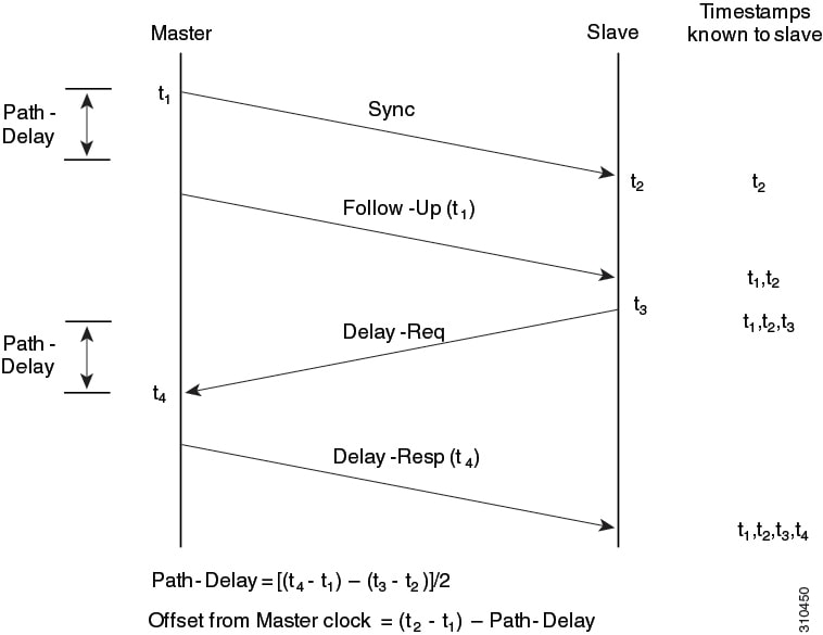
    Event messages that generate and communicate timing information

Guidelines and Limitations for PTP


Note


For scale information, see the release-specific Cisco Nexus 9000 Series NX-OS Verified Scalability Guide.


The following are the guidelines and limitations for Cisco Nexus 9000 series switches for PTP:

  • For optimal PTP performance, it is recommended to use the latest SUP and LC FPGA versions for the release.

  • PTP domain is limited to a single domain per network.

  • PTP transport over User Datagram Protocol (UDP) is supported. Transport over Ethernet is not supported.

  • PTP supports multicast communication. PTP also supports unicast communication and the unicast mode is optional.

  • PTP supports boundary clock mode. End-to-end transparent clock and peer-to-peer transparent clock modes are not supported.

  • It is recommended that the PTP device can either have multicast or unicast PTP mode configured, but not both multicast and unicast mode together.

  • PTP can be enabled on port-channel member ports.

  • All management messages received on a Slave port is forwarded on all PTP enabled ports. Handling management messages is not supported.

  • One-step PTP is only supported on Cisco Nexus 9000-R series platform switches.

  • Timestamp Tagging (TTAG) is supported on the following platform switches:

    • Cisco Nexus 9200 Series Platform Switches: beginning with Cisco NX-OS Release 7.0(3)I6(1)

    • Cisco Nexus 9364C: beginning with Cisco NX-OS Release 7.0(3)I7(2)

    • Cisco Nexus 9332C: beginning with Cisco NX-OS Release 9.2(3)

    • Cisco Nexus 9300-EX Series Platform Switches: beginning with Cisco NX-OS Release (7.0(3)I6(1)

    • Cisco Nexus 9300-FX platform switches: beginning with Cisco NX-OS Release 7.0(3)I7(3)

    • Cisco Nexus 9500 platform switches with -EX and -FX line cards

  • To match PTP control packets using RACL, enable PIM on the L3 interface.

  • When PTP is configured on a Cisco Nexus 9000 series switches, set the clock protocol to use PTP through the clock protocol ptp vdc 1 command. NTP cannot coexist with PTP on a Cisco Nexus 9000 series switch.

  • PTP is supported for all Cisco Nexus 9000 series switches and 3164Q hardware except for the 100G 9408PC line card and the 100G M4PC generic expansion module (GEM).

  • Beginning with Cisco NX-OS Release 9.2(3), PTP is supported on the N9K-C9504-FM-R.

  • For Cisco Nexus 31108PC-V and 31108TC-V switches, PTP is not supported on ports running at 100G speed.

  • Cisco Nexus 9000 series switches support mixed non-negotiated mode of operation on master PTP ports. That means when a slave client sends unicast delay request PTP packet, the Cisco Nexus 9000 responds with an unicast delay response packet. And, if the slave client sends multicast delay request PTP packet, the Cisco Nexus 9000 responds with a multicast delay response packet. For mixed non-negotiated mode to work, the source IP address used in the ptp source IP address configuration on the BC device must also be configured on any physical or logical interface of the BC device. The recommended best practice is to use the loopback interface of the device.

  • Cisco Nexus 9000 series switches support mixed non-negotiated mode of operation on master PTP ports. Meaning that when a slave client sends unicast delay request PTP packet, the Cisco Nexus 9000 responds with an unicast delay response packet. And, if the slave client sends multicast delay request PTP packet, the Cisco Nexus 9000 responds with a multicast delay response packet.

  • Beginning with Cisco NX-OS Release 9.2(1), Cisco Nexus 9732C-EX, 9736C-EX, and 97160YC-EX line cards support PTP offloading.

  • PTP offload is not supported on the Cisco Nexus 9508 switch with an -R series line card.

  • PTP is not supported on the Cisco Nexus 9504 switch with an -R series line card.

  • PTP offload is not supported on the Cisco N3K-C36180YC-R and N3K-C3636C-R line cards.

  • Beginning with Cisco NX-OS Release 9.2(1), Cisco Nexus 9636C-RX, 9636C-R, and 9636Q-R line cards support IEEE 802.1AS. IEEE 802.1AS is not supported on the Cisco Nexus 96136YC-R line card or the Cisco Nexus 9504 switch.

  • PTP is not supported on the Cisco Nexus 96136YC-R line card.

  • Cisco Nexus 93108TC-EX and 93180YC-EX switches support PTP mixed mode and unicast mode. The Cisco Nexus 9396 switch supports PTP mixed mode.

  • PTP is supported with sync interval -3 only on Cisco Nexus 9508-R line cards. Higher sync intervals are not supported.

  • PTP unicast is supported only on the default vrf.

  • PTP supports unicast communication on Cisco Nexus 9508 switches with 9636C-R, 9636C-RX, and 9636Q-R line cards.

  • PTP unicast mode on the Layer2 SVI interfaces is not supported on Cisco Nexus 9508 switches with 9636C-R, 9636C-RX, and 9636Q-R line cards.

  • PTP configuration with UC and MC on either side is not supported on Cisco Nexus 9508 switches with 9636C-R and 9636Q-R line cards.

  • PTP is not supported on FEX interfaces.

  • PTP-capable ports do not identify PTP packets and do not time-stamp or redirect those packets unless you enable PTP on those ports.

  • Cisco Nexus 9500 platform switches with 9700-EX line cards support timestamp tagging.

  • Each port can be individually configured with any of the supported PTP profiles. Different PTP profiles can coexist on an interface. Combination of the default of 1588 and SMPTE-2059-2 or AES67 profiles is supported. However, combination of SMPTE-2059-2 and AES67 profiles is not supported on the same interface.

  • Unicast negotiation is not supported for IPv4 unicast communication for all Nexus 9000 switches.

Default PTP Parameters

The following table lists the default settings for PTP parameters.

Table 1. Default PTP Parameters
Parameters Default

PTP

Disabled

PTP version

2

PTP domain

0

PTP priority 1 value when advertising the clock

255

PTP priority 2 value when advertising the clock

255

PTP announce interval

1 log second

PTP announce timeout

3 announce intervals

PTP delay-request interval

  • 0 log seconds

  • -1 log seconds for Cisco Nexus 3232C, 3264Q, and 9500 platform switches

PTP sync interval

  • -2 log seconds

  • -3 log seconds for Cisco Nexus 3232C, 3264Q, and 9500 platform switches

PTP VLAN

gPTP supports only default vlan 1, and no other user configured VLANs.

Configure PTP

Configure PTP Globally

You can enable or disable PTP globally on a device. You can also configure various PTP clock parameters to help determine which clock in the network has the highest priority to be selected as the grandmaster.


Note


You must always set the clock protocol PTP vdc1 for the local clock to be updated by the PTP protocol, irrespective of the one-step or the two-step mode. You can verify the configuration using the show running-config clock_manager command.

Procedure


Step 1

Enter the global configuration mode using the command configure terminal

Example:

switch# configure terminal
switch(config)#

Step 2

Enable or disable PTP on the device using the command [ no ] feature ptp

Example:

switch(config)# feature ptp

Note


Enabling PTP on the switch does not enable PTP on each interface.

Step 3

Configure the device type as gPTP or boundary clock using the command [ no ] ptp device-type [ generalized-ptp | boundary-clock ]

Example:

switch(config)# ptp device-type generalized-ptp
The generalized-ptp option is available only for Cisco Nexus 9508 switches with an -R series line card .

Step 4

Configure the source IPv4/IPv6 address for all the PTP packets in the multicast PTP mode using the command [ no ] ptp source {<ipv4 address> | <ipv6 address>} . If the IP address is in non-default VRF, use the vrf parameter to configure the VRF using the command [ no ] ptp source { <ipv4 address> | <ipv6 address> } [ vrf<vrf-name> ] .

Example:

switch(config)# ptp source 10.10.10.1

Corresponding source address (IPv4/IPv6) is needed before enabling PTP IPv4/IPv6 transport on an interface.

Note


IPv6 source is supported on Cisco Nexus 93180TC-FX3S switch starting with 10.2(1)F release.

Step 5

Configure the optional commands as needed.

  • Configure the domain number to use for this clock using the command [ no ] ptp domainnumber

    PTP domains allow you to use multiple independent PTP clocking subdomains on a single network. The range for the number is from 0 to 127.

  • Increase the number of PTP sessions by offloading some timers to the line card uisng the comand [ no ] ptp offload

    This step is required for one-step mode and optional for two-step mode.

  • Configure the PTP clock operation to the one-step mode using the command [ no ] ptp clock-operation one-step

    In this case, the timestamp message is sent as a part of the sync message. A followup message is not sent in this mode.

  • Configure the priority1 value to use when advertising this clock using the command [ no ] ptp priority1value

    This value overrides the default criteria (clock quality, clock class, and so on) for best master clock selection. Lower values take precedence. The range for the value is from 0 to 255.

    Note


    For the switch to synchronize with an external Grand Master clock, the local switch PTP priority value must be configured higher than that of external Grand Master Clock priority.

  • Configure the priority2 value to use when advertising this clock using the command [ no ] ptp priority2value

    This value is used to decide between two devices that are otherwise equally matched in the default criteria. For example, you can use the priority2 value to give a specific switch priority over other identical switches. The range for the value is from 0 to 255.

    Note


    For the switch to synchronize with an external Grand Master clock, the local switch PTP priority value must be configured higher than that of external Grand Master Clock priority.

Example:

switch(config)# ptp domain 1 
switch(config)# ptp offload
switch(config)# ptp clock-operation one-step
switch(config)# ptp priority1 1
switch(config)# ptp priority2 1

Step 6

Configure support for PTP management packets using the command [ no ] ptp management

Example:

switch(config)# ptp management
switch(config-ptp-profile)#

This command is enabled by default. no : Disables support for management packets.

Step 7

Configure the optional commands as needed.

  • Enable the PTP profile and enter the PTP profile configuration mode using the command [ no ] ptp profile { 8275-1 | default }

    Note


    This command is supported beginning with Cisco NX-OS Release 9.3(5) and only on the N9K-C93180YC-FX3S platform switch. For more information, see Configure PTP Telecom Profile .

  • Configure the PTP delay mean path/reverse path tolerance variation using the command [ no ] ptp delay tolerance { mean-path | reverse-path } variation

    mean-path : Ignore spikes in Mean Path Delay (MPD) as calculated by the PTP BMC algorithm.

    reverse-path : Ignore spikes in (t4-t3) as calculated by the PTP BMC algorithm.

    variation : Percentage that defines the tolerance for spikes. Use numeric values with a single decimal. Range is from 1.0 through 100.0.

    Note


    This command is supported beginning with Cisco NX-OS Release 9.3(5).

  • Configure the switch to forward all PTPv1 packets based on the forwarding rule using the command ptp forward-version1

    Note


    If you do not enable this command, all PTPv1 packets are passed on to the CPU and ultimately dropped.

    This command is supported beginning with Cisco NX-OS Release 9.3(6).

  • Enable PTP unicast sessions to transition to negotiated mode using the command ptp unicast-negotiation .

    This configuration is introduced in Cisco Nexus NX-OS Release 10.2(1)F and is supported on 93180YC-FX3S.

    For more information, refer to the PTP Unicast-Negotiation section.

  • Set the transmit scope for PTP over IPv6 multicast configuration using the command ptp ipv6 multicast scope tx<scope>

    Note

     
    • Transmit scope is a single value. This determines the scope of IPv6 multicast destination address (FF0’X’) used by PTP packets transmitted by the switch.

    • The default value is 1 ( 0x1 ).

    • When interface level configuration is applied, it takes precedence over the corresponding global configuration.

  • Set the receive scope for PTP over IPv6 multicast configuration using the command ptp ipv6 multicast scope rx<scope>

    Note

     
    • Receive scope can be a single value or multiple values or a range of values. This determines the acceptable scope (FF0’X’) for received IPv6 multicast PTP packets.

    • The default value is 1 through 0xE ( 0x1-0xE ).

    • When interface level configuration is applied, it takes precedence over the corresponding global configuration.

  • Enable the PTP time distribution hold feature using the command [ no ] ptp time distribution-hold [ correction-threshold <corr_limit>] [ delay-threshold <max_delay_time>]

    correction-threshold — Holds the time distribution until the correction settles down to the specified correction value in nanoseconds.

    delay-threshold — Sets the maximum time limit in seconds to hold the time-distribution. However, if correction threshold is met before the delay threshold, the time distribution resumes.

    Default correction threshold is 300 nanoseconds. Default delay threshold is 300 seconds for TOR and 900 seconds for modular chassis.

    The maximum correction threshold is 100000 nanoseconds. The maximum delay threshold is 5000 seconds.

  • Copy the running configuration to the startup configuration using the command copy running-config startup-config

Example:

switch(config)# ptp profile default
switch(config-ptp-profile)#
switch(config)# ptp delay tolerance mean-path 50.5
switch(config)#
switch(config)# ptp forward-version1
switch(config)#
switch(config)# ptp ipv6 multicast scope tx 0x2
switch(config)# ptp ipv6 multicast scope rx 0x1-0x5,0x8,0xA-0xE
switch(config)# ptp time distribution-hold correction-threshold 90000ns delay threshold 4000s
switch(config)# copy running-config startup-config

Configure PTP on an Interface

After you globally enable PTP, it is not enabled on all supported interfaces by default. You must enable PTP interfaces individually.

Before you begin

Make sure that you have globally enabled PTP on the switch and configured the source IP address for PTP communication.

Procedure


Step 1

Enter global configuration mode using the command configure terminal

Example:

switch# configure terminal
switch(config)#

Step 2

Specify the interface on which you are enabling the PTP and enter the interface configuration mode using the command interface ethernetslot/port

Example:

switch(config)# interface ethernet 2/1
switch(config-if)#

Step 3

Enable or disable PTP on an interface using the command [ no ] ptp

Example:

switch(config-if)# ptp

Step 4

Proceed with the following optionals commands as needed.

  • Configure the source IP address for unicast messages using the command ptp ucast-source { <ipv4-addr> | <ipv6-addr> } [ vrf<vrf-name> ]

    ipv4-address : The IPv4 address of the unicast source. This is used when transport is set to IPv4.

    vrfvrf-name : The name of the VRF used for hello messages.

    ipv6-address : The IPv6 address of the unicast source. This is used when transport is set to IPv6.

    Note


    IPv6 is supported on Cisco Nexus 93180YC-FX3S beginning with Cisco NX-OS Release 10.2(1)F.

  • Configure the interval between PTP announce messages on an interface or the number of PTP intervals before a timeout occurs on an interface using the command [ no ] ptp announce { intervallog-seconds | timeoutcount }

    The range for the PTP announcement interval is from 0 to 4 log seconds, and the range for the interval timeout is from 2 to 4 intervals.

  • Configure the interval between PTP announce messages on an interface using the command [ no ] ptp announce interval [ aes67 | smpte-2059 ] log-seconds

    Table 2. PTP Announcement Interval Range and Default Values

    Option

    Range

    Default Value

    aes67-2015

    0 to 4 log seconds

    1 log second

    smpte-2059-2

    –3 to 1 log seconds

    1 log second

    Without the aes67 or smpte-2059 option

    0 to 4 log seconds

    1 log second

  • Configure the minimum interval allowed between PTP delay messages when the port is in the master state using the command [ no ] ptp delay-request minimum intervallog-seconds

    The range is from log(–1) to log(6) seconds, where log(–1) = 2 frames every second.

  • Configure the minimum interval allowed between PTP delay messages when the port is in the master state using the command [ no ] ptp delay-request minimum interval [ aes67-2015 | smpte-2059-2 ] log-seconds

    Table 3. PTP Delay-Request Minimum Interval Range and Default Values

    Option

    Range

    Default Value

    aes67-2015

    –4 to 5 log seconds

    0 log seconds

    smpte-2059-2

    –4 to 5 log seconds

    0 log seconds

    Without the aes67-2015 or smpte-2059-2 option

    –1 to 6 log seconds (where –1 = 2 frames every second)

    0 log seconds

  • Configure the interval between PTP synchronization messages on an interface using the command [ no ] ptp sync intervallog-seconds

    The range is from log(–3) to log(1) seconds. For the media-related profile information, see the Cisco NX-OS IP Fabric for Medial Solution Guide when configuring PTP for media.

  • Configure the interval between PTP synchronization messages on an interface using the command [ no ] ptp sync interval [ aes67-2015 | smpte-2059-2 ] log-seconds

    Table 4. PTP Synchronization Interval Range and Default Values

    Option

    Range

    Recommended Value

    aes67-2015

    –7 to 0 log seconds

    –3 log seconds

    smpte-2059-2

    –7 to –0 log seconds

    –3 log seconds

  • Specify the VLAN for the interface where PTP is being enabled using the command [ no ] ptp vlanvlan-id

    You can only enable PTP on one VLAN on an interface. The range is from 1 to 4094.

  • Accept and respond to the nonforwardable destination MAC address packets using the command ptp destination-mac non-forwardable rx-no-match accept

    These destination MAC addresses are used in the PTP messages that are exchanged between the GM clock, PTP-master clock, and PTP-slave clocks. This command is supported beginning with Cisco NX-OS Release 9.3(5) and only on the Cisco Nexus 93180YC-FX3S switch.

Example:

switch(config)# ptp ucast-source 10.1.1.40
switch(config-if)# ptp announce interval 3
switch(config-if)# ptp announce interval aes67 3
switch(config-if)# ptp delay-request minimum interval -1
switch(config-if)# ptp delay-request minimum interval aes67-2015-1
switch(config-if)# ptp sync interval 1
switch(config-if)# ptp sync interval aes67 1
switch(config-if)# ptp vlan 1
switch(config-if)# ptp destination-mac non-forwardable rx-no-match accept
switch(config-if)#

Step 5

(Optional) Proceed with the following optionals commands as needed

  • Display the PTP status using the command show ptp brief

  • Display the status of the PTP port using the command show ptp port interfaceinterface slot/port

  • Set the transmit scope for PTP over IPv6 multicast configuration using the command ptp ipv6 multicast scope tx<scope>

    Note

     
    • Transmit scope is a single value. This determines the scope of IPv6 multicast destination address (FF0’X’) used by PTP packets transmitted by the switch.

    • The default value is 1 ( 0x1 ).

    • When interface level configuration is applied, it takes precedence over the corresponding global configuration.

  • Set the receive scope for PTP over IPv6 multicast configuration using the command ptp ipv6 multicast scope rx<scope>

    Note

     
    • Receive scope can be a single value or multiple values or a range of values. This determines the acceptable scope (FF0’X’) for received IPv6 multicast PTP packets.

    • The default value is 1 through 0xE ( 0x1-0xE ).

    • When interface level configuration is applied, it takes precedence over the corresponding global configuration.

    • Copy the running configuration to the startup configuration using the command copy running-config startup-config

Example:

switch(config-if)# show ptp brief
switch(config-if)# show ptp port interface ethernet 2/1
switch(config)# ptp ipv6 multicast scope tx 0x2
switch(config)# ptp ipv6 multicast scope rx 0x1-0x5,0x8,0xA-0xE
switch(config-if)# copy running-config startup-config

Configure PTP in Unicast Mode

Configure Unicast Mode

Traditional PTP messages are delivered to the nodes that are capable of receiving PTP multicast messages. (For example, announce , sync , delay_req , delay_resp and follow_up ). In Unicast mode, all PTP messages are delivered only to a particular PTP node. Multicast address is not used. In unicast mode, you can configure master/slave role and assign corresponding peer slave/master IP addresses.

Up to 8 master IPs can be configured for a slave unicast port and 64 slave IPs can be configured for a master port with a maximum 256 slave IP total for all ports. The following commands are used to configure the unicast slave IPs and unicast master IPs. Unicast packets are only sent to and received from these IPs. Packets received from other IPs are ignored.

switch(config-if)# ptp transport ipv4 ucast master 
switch(config-if-ptp-master)# slave ipv4 10.10.10.2 

switch(config-if)# ptp transport ipv4 ucast slave 
switch(config-if-ptp-slave)# master ipv4 10.10.10.1 

Assign Master Role

Complete the following steps to assign a master role:

Procedure

Step 1

Enter global configuration mode using the command configure terminal

Example:
switch# configure terminal
                        switch(config)#
                    

Step 2

Specify the interface on which you enable PTP and enter the interface configuration mode using the commandinterface ethernetslot/port

Example:
switch(config)# interface ethernet 2/1
                        switch(config-if)#

Step 3

Enable PTP master on a particular port (Layer 3 interface) using the command [ no ] ptp transport ipv4 ucast master

Example:
switch(config-if)# ptp transport ipv4 ucast master
                        switch(config-if-ptp-master)#
                    

In the master sub-mode, you can enter the slave IPv4 addresses.

Step 4

Enter the slave IPv4 addresses using the command slave ipv4<IP_address>

Example:
switch-1(config)# interface ethernet 1/1
                        switch-1(config-if)# ptp transport ipv4 ucast master
                        switch-1(config-if-ptp-master)# slave ipv4 1.2.3.1
                        switch-1(config-if-ptp-master)# slave ipv4 1.2.3.2
                        switch-1(config-if-ptp-master)# slave ipv4 1.2.3.3
                        switch-1(config-if-ptp-master)# slave ipv4 1.2.3.4
                        switch-1(config-if-ptp-master)#

Maximum of 64 IP addresses are allowed per master, but this number varies and it depends on the sync interval configuration. The master sends announce, sync, follow-up, and delay_resp only to these slave addresses. You must make sure that the slave IP is reachable.


Assign Slave Role

Procedure

Step 1

Enter the global configuration mode using the command configure terminal

Example:
switch# configure terminal
                        switch(config)#
                    

Step 2

Specify the interface on which you enable PTP and enter the interface configuration mode using the commandinterface ethernetslot/port

Example:
switch(config)# interface ethernet 2/1
                        switch(config-if)#

Step 3

Enable PTP slave on a particular port (Layer 3 interface) using the command [ no ] ptp transport ipv4 ucast slave

Example:
switch(config-if)# ptp transport ipv4 ucast slave
                        switch(config-if-ptp-slave)#
                    

In the slave sub-mode, you can enter the master IPv4 addresses.

Step 4

Enter the master IPv4 addresses using the commandmaster ipv4<IP_address>

Example:

                        switch-1(config)# interface ethernet 1/1
                        switch-1(config-if)# ptp transport ipv4 ucast slave
                        switch-1(config-if-ptp-slave)# master ipv4 4.4.4.1
                        switch-1(config-if-ptp-slave)# master ipv4 4.4.4.2
                        switch-1(config-if-ptp-slave)# master ipv4 4.4.4.3

Configure Unicast Source Address


Note


For all releases up to, and including Cisco NX-OS Release 9.3(4), if the PTP configuration on the interface is changed from unicast to multicast or unicast slave to unicast master, you must reconfigure the unicast source address.


Complete the following steps to configure unicast source address:

Procedure

Step 1

Enter global configuration mode using the command configure terminal

Example:
switch# configure terminal
                        switch(config)#
                    

Step 2

Specify the interface on which you enable the PTP and enter the interface configuration mode using the following command interface ethernetslot/port

Example:
switch(config)# interface ethernet 2/1
                        switch(config-if)#

Step 3

Configure the PTP source address per interface level using the following command [ no ] ptp ucast-sourceipv4-address

Example:
switch(config-if)# ptp ucast-source 10.10.10.20
                        switch(config-if)#

This IP address is used only for unicast PTP messages. The PTP unicast source IP address must be reachable.


Timestamp Tagging

The timestamp tagging feature provides precision time information to track in real time when packets arrive at remote devices. Packets are truncated and timestamped using PTP with nanosecond accuracy. Using the TAP aggregation functionality on the switch, along with the Cisco Nexus Data Broker, you can copy the network traffic using SPAN, filter and timestamp the traffic, and send it for recording and analysis.

If you configure ttag on an interface, all incoming traffic will be tagged. If you configure ttag-strip on an interface all outgoing traffic with ttag will be removed.

Configure Timestamp Tagging


Note


Configuring timestamp tagging is not supported on Cisco Nexus 9508 switches with 9636C-R, 9636C-RX, and 9636Q-R line cards.

Procedure


Step 1

Enter the global configuration mode using the command configure terminal

Example:

switch# configure terminal
switch(config)#

Step 2

Enter the interface configuration mode for the specified interface using the command interfacetype slot/port

Example:

switch(config)# interface ethernet 2/2
switch(config-if)#

Step 3

Configure the timestamp tagging on the Layer 2 or Layer 3 egress interface using the command [ no ] ttag

Example:

switch(config-if)# ttag

This is required on the ingress port for the traffic that needs to be tagged when egressing the switch. This is not required on the egress port.


Configure TTAG Marker Packets and Time Interval

The ttag timestamp field attaches a 48-bit timestamp on the marker packet. This 48-bit timestamp is not a human familiar ASCII based timestamp. To make this 48-bit timestamp human readable, the ttag marker packet can be used to provide additional information to decode the 48-bit timestamp information.

Field

Position (byte:bit)

Length

Definition

Magic

16

By default, this field displays A6A6. This enables to identify ttag-marker packets on the packet stream.

Version

8

Version number. The default version is 1.

Granularity

16

This field represents the granularity of the 48-bit timestamp size. By default, the value is 04, which is 100 picoseconds or 0.1. nanoseconds.

UTc_offset

8

The utc_offset between the ASIC and the UTC clocks. The default value is 0.

Timestamp_hi

32

The high 16-bit of 48- bit ASIC hardware timestamp.

Timestamp_lo

32

The low 32-bit of 48- bit ASIC hardware timestamp.

UTC sec

32

The seconds part of UTC timestamp from the CPU clock of the Cisco Nexus 9000 Series switch.

UTC nsec

32

The nanoseconds part of UTC timestamp from the CPU clock of the Cisco Nexus 9000 Series switch.

Reserved

32

Reserved for future use.

Signature

32

The default value is 0xA5A5A5A5. This allows a forward search of marker packet and provide references to the UTC timestamp, so the client software can use that reference UTC to recover the 32-bit hardware timestamp in each packet header.

Pad

8

This is align byte to convert the ttag-marker align to 4 byte boundary.

Procedure


Step 1

Enter global configuration mode using the command configure terminal

Example:

switch# configure terminal
switch(config)#

Step 2

Configure the seconds that a switch will take to send a ttag-marker packet to the outgoing ports using the command ttag-marker-intervalseconds

Example:

switch(config-if)# ttag-marker-interval 90

This is a global setting to the switch. By default, it sends a ttag-marker packet every 60 seconds. The range for seconds is from 1 to 25200.

Step 3

Enter the interface configuration mode for the specified interface using the command interfacetype slot/port

Example:

switch(config)# interface ethernet 2/2
switch(config-if)#

Step 4

Send the ttag-marker packets to the outgoing port using the command [ no ] ttag-marker enable

Example:

switch(config-if)# ttag-marker enable

Step 5

Remove TTAG from egress packets on the interface using the command ttag-strip

Example:

switch(config-if)# ttag-strip

Configure PTP Interface to Stay in Master State

This procedure describes how to prevent an endpoint from causing a port to transition to a slave state.

Before you begin

  • Make sure that you have globally enabled PTP on the switch and configured the source IP address for PTP communication.

  • After you globally enable PTP, it is not enabled on all supported interfaces by default. You must enable PTP interfaces individually.

Procedure


Step 1

Enter global configuration mode using the command : switch # configure terminal

Step 2

Specify the interface on which you are enabling PTP and enters interface configuration mode using the command switch(config) # interface ethernetslot/port

Step 3

Enable or disable PTP on an interface using the command switch(config) # ptp

Step 4

Configure the port to maintain the master state using the command switch(config-if) #ptpmulticastmaster-only ptpmulticastmaster-only

Example:


                switch(config)# 
                show ptp brief
                PTP port status
                ----------------------------------
                Port                  State 
                ----------------  ----------------
                Eth1/1              Slave
                switch(config)# 
                interface ethernet 1/1
                switch(config-if)# 
                ptp multicast master-only
                2001 Jan  7 07:50:03 A3-MTC-CR-1 %$ VDC-1 %$ %PTP-2-PTP_GM_CHANGE: Grandmaster clock has changed
                 from 60:73:5c:ff:fe:62:a1:41 to 58:97:bd:ff:fe:0d:54:01 for the PTP protocol
                2001 Jan  7 07:50:03 A3-MTC-CR-1 %$ VDC-1 %$ %PTP-2-PTP_STATE_CHANGE: Interface Eth1/1 change from
                 PTP_BMC_STATE_SLAVE to PTP_BMC_STATE_PRE_MASTER
                2001 Jan  7 07:50:03 A3-MTC-CR-1 %$ VDC-1 %$ %PTP-2-PTP_TIMESYNC_LOST: Lost sync with  master clock
                2001 Jan  7 07:50:07 A3-MTC-CR-1 %$ VDC-1 %$ %PTP-2-PTP_STATE_CHANGE: Interface Eth1/1 change from
                 PTP_BMC_STATE_PRE_MASTER to PTP_BMC_STATE_MASTER
            

Verify PTP Configuration

Use one of the following commands to verify the configuration:

Table 5. PTP Show Commands
Command Purpose
show ptp brief

Displays the PTP status.

show ptp clock

Displays the properties of the local clock, including clock identity.

show ptp clock foreign-masters-record

Displays the state of foreign masters known to the PTP process. For each foreign master, the output displays the clock identity, basic clock properties, and whether the clock is being used as a grandmaster.

show ptp corrections

Displays the last few PTP corrections.

show ptp counters [all | interface ethernet slot/port]

Displays the PTP packet counters for all interfaces or for a specified interface.

show ptp parent

Displays the properties of the PTP parent.

show ptp port interface ethernet slot/port

Displays the status of the PTP port on the switch.

show ptp time-property

Displays the PTP clock properties.

show ttag brief

Displays the status of the timestamp tagging configuration.

Note

 
Timestamp tagging configuration is not supported on Cisco Nexus 9508 switches with 9636C-R, 9636C-RX, and 9636Q-R line cards.
show running-config ptp [all]

Displays the running configuration for PTP.

clear ptp counters [all | interface ethernet slot/port]

Clears all PTP messages that are received and transmitted on a specific interface or on all interfaces that has PTP enabled.

clear ptp corrections

Clears the history of the PTP corrections.

Configuration Examples

This example shows how to configure PTP globally on the device, specify the source IP address for PTP communications, and configure a preference level for the clock:

switch# configure terminal
switch(config)# feature ptp
switch(config)# ptp source 10.10.10.1
switch(config)# ptp priority1 1
switch(config)# ptp priority2 1
switch(config)# show ptp brief
PTP port status
-----------------------
Port State
------- --------------
switch(config)# show ptp clock
PTP Device Type: Boundary clock
Clock Identity : 0:22:55:ff:ff:79:a4:c1
Clock Domain: 0
Number of PTP ports: 0
Priority1 : 1
Priority2 : 1
Clock Quality:
  Class : 248
  Accuracy : 254
  Offset (log variance) : 65535
Offset From Master : 0
Mean Path Delay : 0
Steps removed : 0
Local clock time:Mon Dec 22 14:13:24 2014

This example shows how to configure PTP on an interface and configure the intervals for the announce, delay-request, and synchronization messages:

switch# configure terminal
switch(config)# interface Ethernet 1/1
switch(config-if)# ptp
switch(config-if)# ptp announce interval 3
switch(config-if)# ptp announce timeout 2
switch(config-if)# ptp delay-request minimum interval smpte-2059-2 -3
switch(config-if)# ptp sync interval smpte-2059-2 -3
switch(config-if)# no shutdown
switch(config-if)# show ptp brief
PTP port status
-----------------------
Port State
------- --------------
Eth2/1 Master
switch(config-if)# show ptp port interface ethernet 2/1
PTP Port Dataset: Eth2/1
Port identity: clock identity: 0:22:55:ff:ff:79:a4:c1
Port identity: port number: 1028
PTP version: 2
Port state: Master
Delay request interval(log mean): 4
Announce receipt time out: 2
Peer mean path delay: 0
Announce interval(log mean): 3
Sync interval(log mean): 1
Delay Mechanism: End to End
Peer delay request interval(log mean): 0

This example shows how to configure master/slave role and assign corresponding peer slave/master IP addresses.


For Cisco NX-OS Release 9.3(4) and earlier:
switch-1(config)# interface ethernet 1/1
switch-1(config-if)# ptp transport ipv4 ucast master
switch-1(config-if-ptp-master)# slave ipv4 1.2.3.1
switch-1(config-if-ptp-master)# slave ipv4 1.2.3.2
switch-1(config-if-ptp-master)# slave ipv4 1.2.3.3
switch-1(config-if-ptp-master)# slave ipv4 1.2.3.4
switch-1(config-if-ptp-master)#

switch-1(config-if)# ptp transport ipv4 ucast slave
switch-1(config-if-ptp-slave)# master ipv4 4.4.4.1
switch-1(config-if-ptp-slave)# master ipv4 4.4.4.2
switch-1(config-if-ptp-slave)# master ipv4 4.4.4.3


switch-1(config-if-ptp-slave)# ptp ucast-source 9.9.9.9


switch-1(config-if)# sh running-config ptp

!Command: show running-config ptp
!Time: Tue Feb  7 17:37:09 2017

version 7.0(3)I4(6)
feature ptp

ptp source 1.1.1.1


interface Ethernet1/1
  ptp transport ipv4 ucast master
    slave ipv4 1.2.3.1
    slave ipv4 1.2.3.2
    slave ipv4 1.2.3.3
    slave ipv4 1.2.3.4

interface Ethernet1/2
  ptp transport ipv4 ucast slave
    master ipv4 4.4.4.1
    master ipv4 4.4.4.2
    master ipv4 4.4.4.3
  ptp ucast-source 9.9.9.9

switch-1(config-if)#