Overview
the Cisco Nexus 93400LD-H1 switch (N9K-C93400LD-H1) is a 1-rack unit (RU) top of rack (TOR) fixed-port switch designed for leaf-role, APIC deployment in data centers. This switch does not support spine role.
The software on this switch has 6.4T traffic-processing capability.
This switch includes the following ports:
-
48 x 50GE ZSFP downlink ports with full MACsec support
-
4 x 400G QSFP-DD uplink ports wth full MACsec support
-
Management port RJ45
-
Console port
-
USB port
-
Time of Day (TOD) port
Port Considerations
These are the port considerations:
-
This switch supports 50G, 25G, or 10G speeds
-
48 x 50G/25G/10G and 4 x 400G/100G
This switch includes these user-replaceable components:
-
Fan modules (five) with these airflow choices:
-
Port-side intake airflow with burgundy coloring (NXA-SFAN-35CFM-PI)
-
Port-side exhaust airflow with blue coloring (NXA-SFAN-35CFM-PE)
-
-
Power supply modules (two—one for operations and one for redundancy [1+1]) with these choices (a mix of AC and DC power sources is only supported for hot swapping purposes, with a time limit of 15 minutes, but do not mix airflow directions):
-
1400-W AC power supply with port-side intake airflow (burgundy coloring) (NXA-PAC-1400W-PI)
-
1400-W AC power supply with port-side exhaust airflow (blue coloring) (NXA-PAC-1400W-PE)
-
2000-W DC power supply with port-side intake airflow (burgundy coloring) (NXA-PDC-2KW-PI)
-
2000-W DC power supply with port-side exhaust airflow (blue coloring) (NXA-PDC-2KW-PE)
-
2000-W HVDC power supply with port-side intake airflow (burgundy coloring) (NXA-PHV-2KW-PI)
-
The figure shows the switch features on the port side of the chassis.
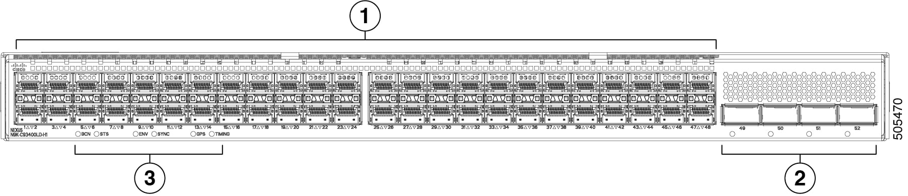
|
1 |
48 50-GE ZSFP downlink ports (ports 1-48) |
2 |
4 400-G QSFP-DD uplink ports (ports 49-52) |
|
3 |
LEDs (BCN, STS, ENV, SYNC, GPS, TIMING) |
 Note |
|
To determine which transceivers, adapters, and cables are support this switch, see the Cisco Transceiver Modules Compatibility Information document.
This figure shows the switch features on the power supply side of the chassis.
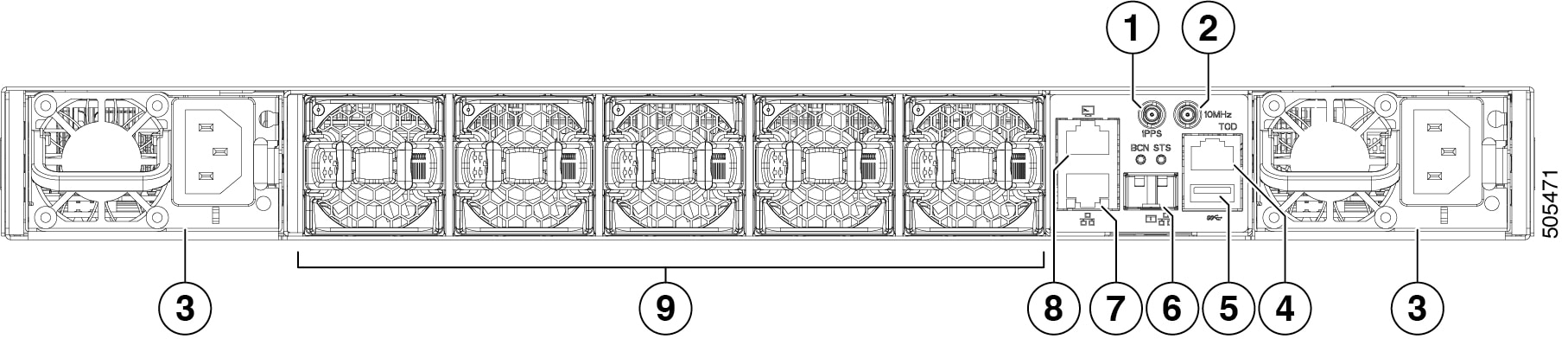
|
1 |
DIN connector (1 PPS) |
2 |
DIN connector (10 MHz) |
|
3 |
Power supply modules (1 or 2) (AC power supplies shown) with slots numbered 1 (right) and 2 (left) |
4 |
Time of Day (ToD) port |
|
5 |
USB port |
6 |
Management port (SFP) |
|
7 |
Management port (RJ45) |
8 |
Console port |
|
9 |
Fan modules (5) with slots numbered 1 (left) to 5 (right) |
This figure shows the switch features on the side of the chassis.
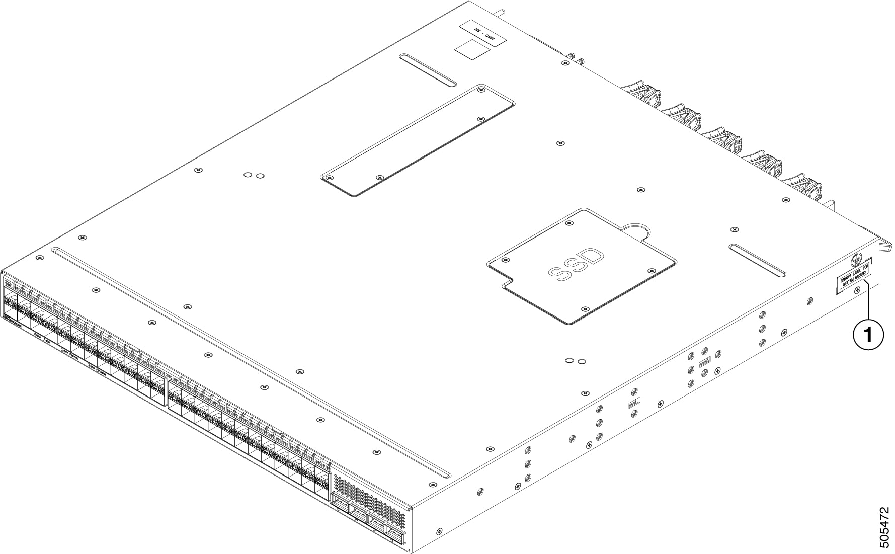
|
1 |
Grounding pad |
The fan and power supply modules are field replaceable. You can replace one fan module or one power supply module during operations so long as the other modules are installed and operating. If you have only one power supply installed, you can install the replacement power supply in the open slot before removing the original power supply.
 Caution |
If the switch has port-side intake airflow (burgundy coloring for fan modules), you must locate the ports in the cold aisle. If the switch has port-side exhaust airflow (blue coloring for fan modules), you must locate the ports in the hot aisle. If you locate the air intake in a hot aisle, the switch can overheat and shut down. |
 Feedback