Overview
The Cisco Nexus 93216TC-FX2 switch (N9K-C93216TC-FX2) is a 2-rack unit (RU), fixed-port switch designed for deployment in data centers. This switch has the following ports:
-
96 100M/1G/10G RJ45 ports
-
12 40/100-Gigabit QSFP28 ports
-
2 management ports (one RJ-45 port and one SFP port)
-
1 console port
-
1 USB port
This switch includes the following user-replaceable components:
-
Fan modules (three) with the following airflow choices:
-
Port-side exhaust fan module with blue coloring (NXA-FAN-160CFM-PE)
-
Port-side intake fan module with burgundy coloring (NXA-FAN-160CFM-PI)

Note
Table 1. Fan Speeds for this Switch Port-Side Intake
Fan Speed %
Port-Side Exhaust
Fan Speed %
Typical/Minimum
40%
70%
Maximum
90%
90%
Note
Each fan module has two rotors. The switch can function normally if one rotor inside the any one fan module fails. In case of more than one rotor failure, the switch will issue a warning and power down in 2 minute.
-
-
Power supply modules (two—one for operations and one for redundancy [1+1]) with the following choices:
-
1200-W port-side exhaust AC power supply with blue coloring (NXA-PAC-1200W-PE)
-
1200-W port-side intake AC power supply with burgundy coloring (NXA-PAC-1200W-PI)
-
1200-W HVAC/HVDC dual-direction airflow power supply with white coloring (N9K-PUV-1200W)
-
930-W port-side exhaust DC power supply with blue coloring (NXA-PDC-930W-PE)
-
930-W port-side intake DC power supply with burgundy coloring (NXA-PDC-930W-PI)
Note
930-W DC power supply support 1+1 redundancy requires both of the following conditions:
-
Ambient temperature of 104°F (40℃) or less and
-
Use of 3.5 W QSFP+ transceivers or passive QSFP cables
With higher temperatures or other optics, the switch requires both power supplies for operations without power redundancy.
Note
Both power supplies should be the same type. Do not mix AC, DC, or HVAC/HVDC power supplies.
Note
All fan modules and power supplies must use the same airflow direction. If you are using the 1200-W HVAC/HVDC power supplies, those power supplies automatically use the same airflow direction as used by the fan modules.
-
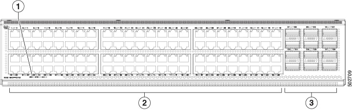
The following figure shows the switch features on the port side of the chassis.
|
1 |
Beacon (BCN), Status (STS), and Environment (ENV) LEDs |
3 |
12 40/100-Gigabit QSFP28 ports |
|
2 |
96 100M/1G/10G RJ45 ports |
To determine which transceivers, adapters, and cables are supported by this switch, see the Cisco Transceiver Modules Compatibility Information document.
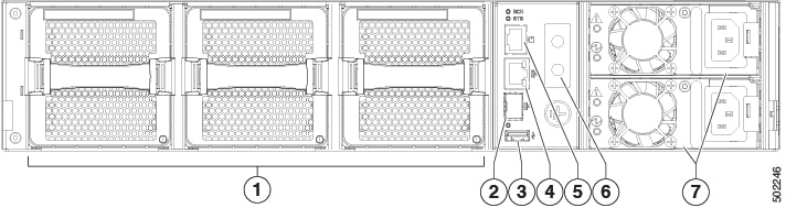
The following figure shows the switch features on the power supply side of the chassis.
|
1 |
Fan modules (3) with slots numbered from 1 (left) to 3 (right) |
5 |
Console port (1) |
|
2 |
Management port (1—SFP optical port) |
6 |
Grounding pad |
|
3 |
USB port (1) |
7 |
Power supply modules (1 or 2) (AC power supplies shown) with slots numbered 1 (top) and 2 (bottom) |
|
4 |
Management port (1—RJ-45 copper port) |
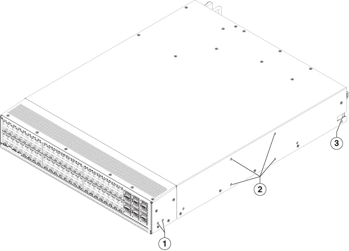
The following figure shows the side of the chassis.
|
1 |
Screw holes for front mounting brackets (four-post rack installations) |
3 |
Notch on both sides of the chassis for locking the power supply end of the chassis to the bottom support rails (four-post rack installations). |
|
2 |
Screw holes for center-mount bracket (two-post rack installations) |
Note |
The access panel for DIMM upgrade is located on the underside of the chassis and uses Philips flat-head screws, M3x0.5x5mmL, CSwZNwPCH,121'. |
Depending on whether you plan to position the ports in a hot or cold aisle, you can order the fan and power supply modules with port-side intake or port-side exhaust airflow. For port-side intake airflow, the fan and AC power supply modules have burgundy coloring. For port-side exhaust airflow, the fan and AC power supplies have blue coloring. You can also order the 1200-W HVAC/HVDC power supply which has dual-direction airflow with white coloring. Dual-direction airflow modules automatically use the airflow direction of the other modules installed in the switch.
The fan and power supply modules are field replaceable and you can replace one fan module or one power supply module during operations so long as the other modules are installed and operating. If you have only one power supply installed, you can install the replacement power supply in the open slot before removing the original power supply.
Note |
All of the fan and power supply modules must have the same direction of airflow. Otherwise, the switch can overheat and shut down. If you are installing a dual-direction power supply, that module will automatically use the same airflow direction as the other modules in the switch. |
 Caution |
If the switch has port-side intake airflow (burgundy coloring for fan modules), you must locate the ports in the cold aisle. If the switch has port-side exhaust airflow (blue coloring for fan modules), you must locate the ports in the hot aisle. If you locate the air intake in a hot aisle, the switch can overheat and shut down. |
 Feedback