Overview
The Cisco Nexus 9332D-H2R switch (N9K-C9332D-H2R) is a 1-rack unit (RU), fixed-port switch designed for deployment in data centers.
The software on this switch has a 12.8T traffic-processing capability.
This switch includes these ports:
-
400-Gigabit QSFP-DD ports (32)
-
10-Gigabit SFP+ ports (2)
-
Management ports (one 10/100/1000BASE-T port and one SFP port)
-
Console port (RS-232)
-
USB port
Default switch role and default port-profile information for this switch:
-
The default switch role is spine: 32 x 400G + 2 x 10G
-
In leaf mode: 24 x 400G + 2 x 10G + 8 x 400G
Leaf/Spine role considerations:
-
This switch's default role is as a spine switch.
-
The default fabric links (ports 25-32) must be used for initial switch discovery via another switch.
-
To change the switch from the default role, the switch must be rebooted (you must select the role of leaf or spine, except in the case of the default spine switch being connected directly to the APIC).
-
Port-profile (downlink/fabric link conversion) can be done after it’s registered to the APIC.
 Note |
From ACI release 6.1(2) and later, you can change the role of any undiscovered switch before the switch is discovered using this CLI command:
|
Note |
The For more information about using this CLI command, see the Cisco APIC Getting Started Guide, Release 6.1(x). |
Discovery considerations:
-
Discovery via APIC – use the default downlink ports (1-24).
-
Spine discovery – use the default fabric links (ports 25-32) and convert the switch to spine (reboot is required).
-
Leaf discovery via spine – use the default fabric links (ports 25-32).
-
Sub leaf discovery via leaf – use the default fabric links (ports 25-32).
-
Multi-Pod first spine discovery via IPN – Connect the IPN to one of the default fabric links (ports 25-32). Ensure the spine has at least one leaf node connected to it.
Note |
400G ZRP optical modules can be plugged in the upper 16 ports only. |
This switch includes these user-replaceable components:
-
Fan modules (6) with these airflow choices:
-
Port-side intake fan module with burgundy coloring (NXA-SFAN-35CFM-PI)
-
-
Power supply modules (two—One for operations and one for redundancy [1+1]) with these choices:
-
2000-W port-side intake AC power supply with burgundy coloring (NXA-PAC-2KW-PI)
-
2000-W port-side intake DC power supply with burgundy coloring (NXA-PDC-2KW-PI)
-
2000-W port-side intake HVDC power supply with burgundy coloring (NXA-PHV-2KW-PI)
Note
All fan modules and power supplies must use the same airflow direction.
Note
Each fan module has two rotors. The switch can function normally if one rotor inside any one fan module fails. In case of more than one rotor failure, the switch will issue a warning and power down in 2 minutes, unless you take corrective action to replace the fan module.
-
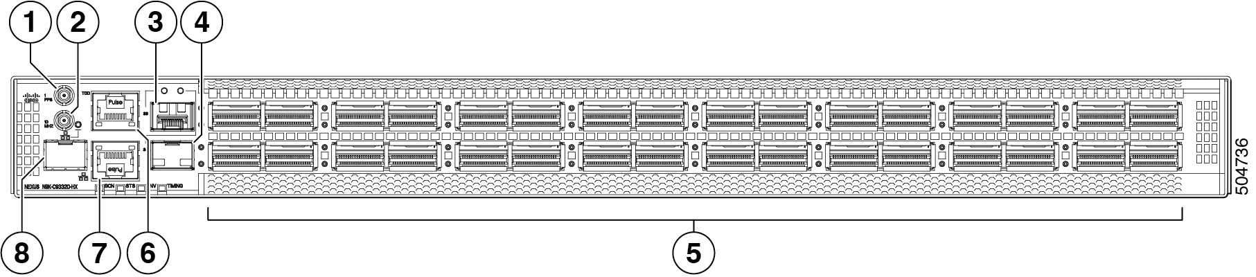
The figure shows the switch features on the port side of the chassis.
|
1 |
Synchronous Ethernet (SyncE) DIN 1.0/2.3 connector (1 PPS) |
2 |
Synchronous Ethernet (SyncE) DIN 1.0/2.3 connector (10 MHz) |
|
3 |
10-Gigabit SFP+ port |
4 |
10-Gigabit SFP+ port |
|
5 |
400-Gigabit QSFP-DD ports (32) |
6 |
Time of Day (ToD) port |
|
7 |
Management port (RJ45) |
8 |
Management port (SFP) |
To determine which transceivers, adapters, and cables are support this switch, see the Cisco Transceiver Modules Compatibility Information document.
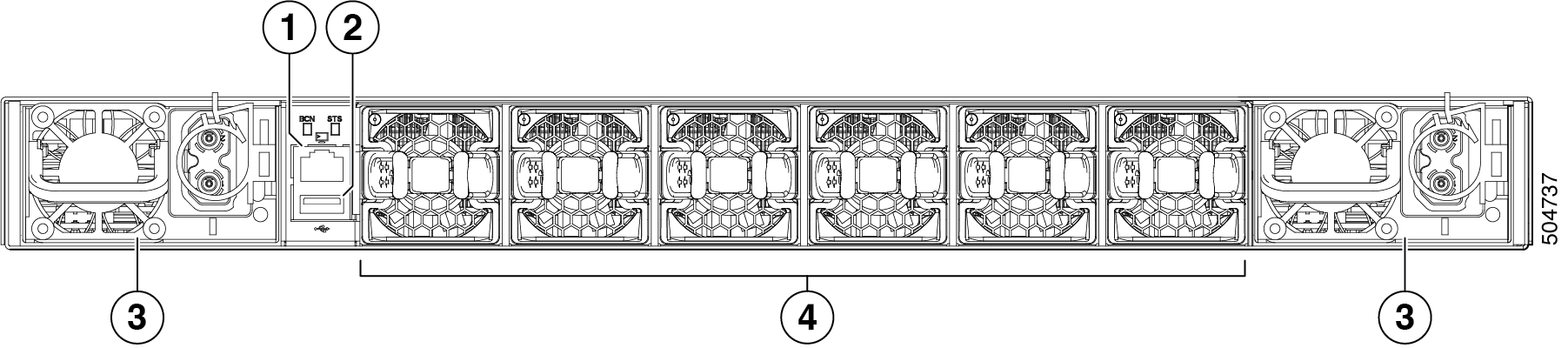
The figure shows the switch features on the power supply side of the chassis.
|
1 |
Console port |
2 |
USB port |
|
3 |
Power supply modules (1 or 2) (DC power supplies shown) with slots numbered 1 (left) and 2 (right) |
4 |
Fan modules (6) with slots numbered from 1 (left) to 6 (right) |
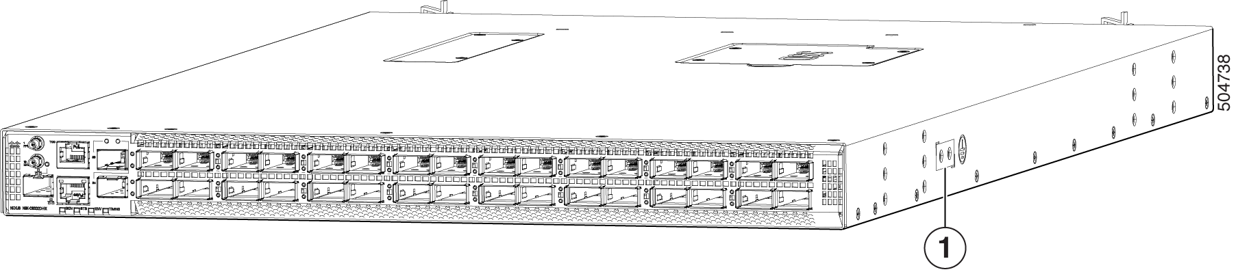
The figure shows the side of the chassis.
|
1 |
Grounding pad |
The fan and power supply modules are field replaceable. You can replace one fan module or one power supply module during operations so long as the other modules are installed and operating. If you have only one power supply installed, you can install the replacement power supply in the open slot before removing the original power supply.
 Caution |
If the switch has port-side intake airflow (burgundy coloring for fan modules), you must locate the ports in the cold aisle. If the switch has port-side exhaust airflow (blue coloring for fan modules), you must locate the ports in the hot aisle. If you locate the air intake in a hot aisle, the switch can overheat and shut down. |
 Feedback