Safety
Before you install, operate, or service the switch, see the Regulatory, Compliance, and Safety Information for the Cisco Nexus 3000 and 9000 Series for important Safety Information.
 Warning |
Statement 1071—Warning Definition IMPORTANT SAFETY INSTRUCTIONS Before you work on any equipment, be aware of the hazards involved with electrical circuitry and be familiar with standard practices for preventing accidents. Read the installation instructions before using, installing, or connecting the system to the power source. Use the statement number provided at the end of each warning statement to locate its translation in the translated safety warnings for this device. SAVE THESE INSTRUCTIONS |
Warning |
Statement 1089—Instructed and Skilled Person Definitions An instructed person is someone who has been instructed and trained by a skilled person and takes the necessary precautions when working with equipment. A skilled person or qualified personnel is someone who has training or experience in the equipment technology and understands potential hazards when working with equipment. |
Warning |
Statement 1004—Installation Instructions Read the installation instructions before using, installing, or connecting the system to the power source. |
Warning |
Statement 1040—Product Disposal Ultimate disposal of this product should be handled according to all national laws and regulations. |
Warning |
Statement 1074—Comply with Local and National Electrical Codes To reduce risk of electric shock or fire, installation of the equipment must comply with local and national electrical codes. |
Warning |
Statement 371—Power Cable and AC Adapter When installing the product, use the provided or designated connection cables, power cables, AC adapters, and batteries. Using any other cables or adapters could cause a malfunction or a fire. Electrical Appliance and Material Safety Law prohibits the use of UL-certified cables (that have the "UL" or "CSA" shown on the cord), not regulated with the subject law by showing "PSE" on the cord, for any other electrical devices than products designated by Cisco. |
 Note |
Statement 407—Japanese Safety Instruction You are strongly advised to read the safety instruction before using the product. https://www.cisco.com/web/JP/techdoc/pldoc/pldoc.html When installing the product, use the provided or designated connection cables/power cables/AC adapters.
|
Warning |
Statement 1017—Restricted Area This unit is intended for installation in restricted access areas. Only skilled, instructed, or qualified personnel can access a restricted access area. |
Warning |
Statement 1030—Equipment Installation Only trained and qualified personnel should be allowed to install, replace, or service this equipment. |
Warning |
Statement 1091—Installation by an Instructed Person Only an instructed person or skilled person should be allowed to install, replace, or service this equipment. See statement 1089 for the definition of an instructed or skilled person. |
Warning |
Statement 1028—More Than One Power Supply This unit might have more than one power supply connection. To reduce risk of electric shock, remove all connections to de-energize the unit.  |
Warning |
Statement 1003—DC Power Disconnection Before performing any of the following procedures, ensure that power is removed from the DC circuit. |
Warning |
Statement 1046—Installing or Replacing the Unit To reduce risk of electric shock, when installing or replacing the unit, the ground connection must always be made first and disconnected last. |
Warning |
Statement 1022—Disconnect Device To reduce risk of electric shock and fire, a readily accessible two-poled disconnect device must be incorporated in the fixed wiring. |
Warning |
Statement 1033—Safety Extra-Low Voltage (SELV)—IEC 60950/ES1–IEC 62368 DC Power Supply To reduce risk of electric shock, connect the unit only to a DC power source that complies with the SELV requirements in IEC 60950-based safety standards or ES1 requirements in IEC 62368-based safety standards. |
Warning |
Statement 1024—Ground Conductor This equipment must be grounded. To reduce the risk of electric shock, never defeat the ground conductor or operate the equipment in the absence of a suitably installed ground conductor. Contact the appropriate electrical inspection authority or an electrician if you are uncertain that suitable grounding is available. |
Warning |
Statement 1252—Equipment Grounding This equipment must be grounded. To reduce the risk of electric shock, the power cord, plug, or combination must be connected to a properly grounded electrode, outlet, or terminal. |
Warning |
Statement 1032—Lifting the Chassis To prevent personal injury or damage to the chassis, never attempt to lift or tilt the chassis using the handles on modules, such as power supplies, fans, or cards. These types of handles are not designed to support the weight of the unit. |
Warning |
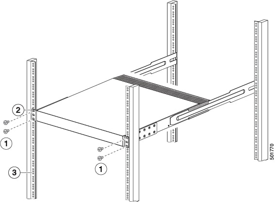
Statement 1006—Chassis Warning for Rack-Mounting and Servicing To prevent bodily injury when mounting or servicing this unit in a rack, you must take special precautions to ensure that the system remains stable. The following guidelines are provided to ensure your safety:
|


 Feedback