Machine Vision in Industrial Automation Environments
Available Languages
Bias-Free Language
The documentation set for this product strives to use bias-free language. For the purposes of this documentation set, bias-free is defined as language that does not imply discrimination based on age, disability, gender, racial identity, ethnic identity, sexual orientation, socioeconomic status, and intersectionality. Exceptions may be present in the documentation due to language that is hardcoded in the user interfaces of the product software, language used based on RFP documentation, or language that is used by a referenced third-party product. Learn more about how Cisco is using Inclusive Language.
- US/Canada 800-553-2447
- Worldwide Support Phone Numbers
- All Tools
 Feedback
 Feedback
Machine Vision in IA Solution Features
Solution Benefits for Machine Vision in Industrial Automation
IEEE 1588 Precise Time Protocol (PTP)
Machine Vision Traffic Types and Patterns
Machine Vision in the IA Architecture
Validated Hardware and Software
Machine Vision Networking and Security Design
Deployment of machine vision analytics
Network Design Recommendations
Latency and Jumbo Frame Support
Machine Vision Security considerations
Access Control, Authentication, and Authorization (ISE)
Visibility With Cisco Cyber Vision
Secure Remote Access (SEA) for Vision Support
Network Segmentation for Machine Vision
Putting It Together: Vision Security Architecture
Standardization Through Templates
Integrated Policy Management with Cisco ISE
Plug-and-Play (PnP) Onboarding for Vision Cells
Lifecycle Management and Upgrades
Campus Automation Capabilities (Layer 2 Automation)
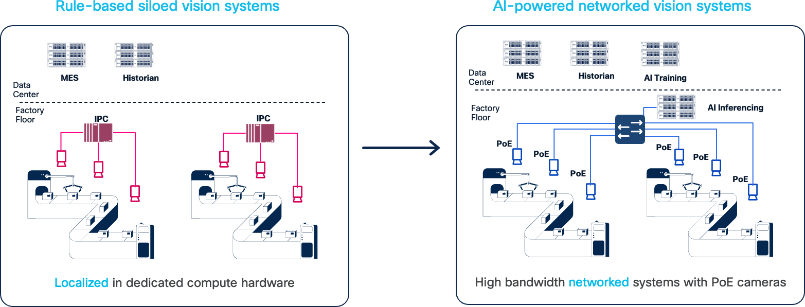
Cisco has been engaged in bringing standard networking and cybersecurity capabilities into manufacturers’ production environment for over 20 years. As with other industries, when internet technologies arrive in industrial automation environments, drastic innovation comes along with it. And that is exactly what is occurring, especially with the introduction of Artificial Intelligence (AI) and Machine Learning (ML) technologies into production systems. These technologies are driving improvements in product quality, increased efficiency and uptime, cost reductions and enabling more automation. The use cases are astounding and abundant. AI is driving improvements in machine vision, adaptive and coordinated robotic operations, manufacturing processes, enabling cloud-based Digital Twins and helping personnel to become more effective and efficient.
Critical to enabling these use cases is the ability to give the AI applications like machine vision analytics, access to the data via secure, high-speed/low-latency, resilient network services. To accelerate and reduce installation costs, the network can also supply power and synchronization to capable sensors and automation devices over the same physical cabling. AI/ML-driven machine vision applications are deployed in the industrial edge – next to or inside the asset. But the information, the vision data, often needs to be analyzed, collected and stored which could be done at the edge, in the plant data center and/or in the enterprise cloud applications. The network needs to provide resilient, flexible, deterministic, high-bandwidth connectivity to connect machine vision systems to AI-driven analytics and more consolidated cloud (private or public) sites for model training and historical retention.
This solution is focused on the network and security designs and implementation best practices to deploy AI-driven machine vision systems. It is based upon and extends our Industrial Automation network and security Cisco Validated Designs (CVDs).
Machine vision in production systems is used for a host of applications – product quality assessment, coordinating robotic operations (such as pick and place, and tool/placement), scanning products or containers for text or barcodes, and safety for mobile assets. The camera sensors used in these applications are also rapidly improving – the granularity with which images are produced and the speed at which they are produced. AI/ML technologies are improving how quickly and effectively the vision data is processed, for example by adapting to changing conditions or processing the data in innovative ways (for example, area-scanning to line-scanning, or 2-D to 3-D scanning). AI/ML is significantly improving on the existing rules-based vision processing.
This solution is focused on accelerating deployments of AI/ML machine visioning systems, helping customers get to the business benefits faster, with less risk and lower costs. The outcomes this technology provide are impressive and include:
● Increased output and reduce waste by reducing the number of false-fails, where a product or process was inappropriately identified as an anomaly, causing waste, output reduction, and slowing overall production.
● Improved product quality by more precisely identifying anomalies, speeding up the time to check a product and adapting to changing lighting or other environmental conditions
● Increased efficiency and speed with shorter image processing time of more granular images for robotic operations or quality checks
● Improved worker and equipment safety when machine vision systems detect unsafe conditions, faster and with more accuracy
● Expanded set of use cases with more cameras enabling 3-D-based analytics of products and processes
● Increased success rate of identifying and reading bar-codes or character-based data on inventory and assets
● Reduced costs by optimizing the use of AI capable computing resources through flexible network connectivity
Machine vision systems are distinctly different than the typical Industrial Automation and Control Systems (IACS). IACS applications, like machine vision, need low-latency, highly resilient networks. But machine vision systems can produce significantly higher volumes of data than typical IACS systems. This is an example of the significant challenges to deploying this technology. These challenges need to be overcome to accelerate adoption of the improved technology.
Key challenges include:
● Lack of bandwidth in production networks to handle the volume of data coming from machine vision cameras for processing or long-term storage
● High cost to deploy the cabling and infrastructure to connect, power and synchronize machine vision cameras and AI-driven vision analytics and inferencing
● Difficulty providing low-latency/jitter communications for other critical traffic applications with the presence of vision-driven high-bandwidth applications
● Ability to access quality data to train the new AI/ML applications due to lack of connectivity
● Complexity in achieving consistent network support for machine vision-generated jumbo frames, which can introduce overhead, latency and jitter when fragmentation occurs or jumbo frames are not supported
● Insufficient prescriptive guidance on required network configurations, leading to uncertainty when deploying machine vision applications at scale
● Security concerns of integrating new devices and moving/storing sensitive image data around the plant networks
This solution will provide guidance based on testing and collaboration with equipment from a set of machine vision vendors on how to overcome these challenges and help manufacturers and the system implementers to accelerate the adoption of this exciting technology.
The key vendor technology tested includes Basler, Cognex, Lucid, and Zebra.
Machine Vision in IA Solution Features
This solution applies the IT/OT converged networking and security concepts and models for deployment and operations of AI-driven machine vision applications, including:
● Lower-cost and quicker deployment of machine vision cameras based on network infrastructure providing:
◦ High-bandwidth (1Gb and 2.5Gb/multi-gig) connectivity for cameras,
◦ 10Gb connectivity for machine vision analytics platforms
◦ PoE/PoE+/4PPoE power over the same Ethernet cabling to enable power-hungry cameras
◦ Synchronization of machine vision activity based on Precise Time Protocol network support reducing the need for I/O cabling
● Overall, the network can reduce the required number of cables from 3 (data, power and I/O signaling) to 1.
● Reliable, low-latency communications of vision data from camera to analytics platforms with QoS and Jumbo Frame support
● Security of machine vision devices and data with Cisco TrustSec network access control
Solution Benefits for Machine Vision in Industrial Automation
By designing, deploying, and testing these systems in our Industrial Automation testing and developing this design and implementation guidance, this solution supplies manufacturing customers, OEMs, system implementers with the following benefits:
● Reduce risk in the production environment through industry-leading security.
● Improve operational equipment effectiveness (OEE) and asset utilization through increased production availability and increased control system and asset visibility.
● Reduce product defects through early indication of quality impacting events or conditions.
● Faster deployment of new lines or line modifications or new plants.
● Faster troubleshooting of equipment (with reduction in connectivity or security-related downtime).
This CVD solution is intended for anyone deploying IACS systems. The solution provides industrial automation network and security design and implementation guidance for vendors, partners, system implementers, customers, and service providers involved in designing, deploying, or operating production systems.
This design and implementation guide provides a comprehensive explanation of the Cisco recommended networking and security for IACS. It includes information about the system architecture, possible deployment models, and guidelines for implementation and configuration. This guide also recommends best practices when deploying the validated reference architecture.
The section provides foundational concepts, building blocks, and considerations for Industrial Automation environments.
Machine Vision systems are typically critical parts of the manufacturing process. They are typically deployed and fit into the Cell/Area zone of the IA architecture. The list below summarizes machine vision network requirements.
● High-bandwidth – vision sensors are becoming faster and have higher resolution leading to more data being produced and transferred. Cameras are often connecting at 1Gb speeds and higher including 2.5 Gb and recently up to 10Gb.
● Low-latency communication - ensures images from the cameras are processed in a timely manner and feedback is given to the industrial controllers on any actions to take.
● Power - Machine vision cameras are becoming more power intensive, requiring PoE types 1–4 PoE (such as PoE, PoE+ and 4PPoE) and benefit from the reduction of cabling costs and deployment effort when PoE from the network is available
● Synchronization - precise time is often needed for coordinated image capture and time-stamping of the images for processing by the AI/ML analytics and inferencing.
● Scale – more cameras are being used to create multi-faceted views of a process or product requiring higher volumes of camera being deployed.
● High availability – vision systems, like control systems, often have keep-alive timers and short processing time requirements, which require networks to be highly available and resilient.
● Retention - Machine vision data often needs to be collected and stored (locally, in an enterprise data center or the cloud) as part of regulatory or historical purposes,
● Security – vision data often represents critical Intellectual Property for manufacturers as it reflects product and process innovations as well as being needed for regulatory or traceability reasons.
As with many other types of devices in the Industrial Automation space, standard communication protocols are needed to enable products from various suppliers to interoperate. The same goes for machine vision systems. This section lists the key machine vision communication standards.
GigE Vision is protocol for controlling vision devices, such as cameras and their peripherals (for example lights, lenses, and so on), and transmitting vision data. GigE Vision enables interoperability between machine vendor cameras and the applications that control them and analyze their data. The standard is managed by the Association for Advancing Automation (A3). The protocol is based on Ethernet and Internet Protocol standards. Many of the machine vision vendors support GigE Vision.
GigE Vision lays out 3 types of communication flows between devices:
● Device Discovery – is a protocol to identify GigE Vision devices and establish communication
● GigE Vision Control Protocol (GVCP) – This part of the protocol enables an application to control/configure a device (e.g. a camera). Only one device/application can control a device. GVCP is based on UDP. Note: there are no authorization or authentication mechanisms established in GVCP.
● GigE Vision Streaming Protocol (GVSP) – This part of the protocol specifies how image data is transferred from transmitters to receivers. GVSP is also based on UDP. GVSP provides application-level packet transmission reliability (retries) and some flow-control mechanisms to manage resources or capacity on the GVSP receivers.
In the QoS section, recommendations are made regarding identifying, marking and prioritizing GVCP and GVSP traffic flows between GigE Vision devices. The considerations take into consideration other traffics flows that are typically found in Industrial Control networks, such as Automation and Control protocols (Profinet, CIP, Modbus, and so on), telemetry, file and data transfers, and others.
More information on the standard is on the A3 website.
IEEE 1588 Precise Time Protocol (PTP)
Machine Vision cameras often must capture images of fast-moving products or processes. Synchronizing the image capture and time-stamping those images is critical to the vision analytic systems. In many cases, this has meant creating I/O connections to the cameras, requiring additional wiring. Now many machine vision cameras now support Precise Time Protocol, a network-based time service, which replaces the need for I/O-based triggering. PTP reduces the need for additional cabling, lowering deployment time and costs. GigE Vision also allows devices to support Precise Time Protocol to manage clocks used for synchronization in GigE Vision devices.
Defined in IEEE1588 as Precision Clock Synchronization for Networked Measurements and Control Systems, PTP was developed to synchronize the clocks in packet-based networks that include distributed device clocks of varying precision and stability. PTP is designed specifically for industrial, networked measurement and control systems, and is optimal for use in distributed systems because it requires minimal bandwidth and little processing overhead. PTP facilitates services which require extremely precise time accuracy and stability like peak-hour billing, virtual power generators, outage monitoring and management, and so on.
PTP was originally developed in 2002. It was enhanced in 2008 (IEEE 1588-2008) and is referred to as PTPv2. This version establishes the basic concept and algorithms for distribution of precise time. These basics have been adopted into “profiles” that are specific definitions for distribution of time designed for particular use cases. Manufacturing environments and most machine vision camera makers predominantly use the Default Profile, but GigE Vision also allows for IEEE 802.1AS time synchronization protocol.
Note: Only the IE9300 currently support IEEE 802.1AS.
AI-Driven Machine Vision systems essentially are deployed in 3 types of deployment models:
● Embedded, where the GPU/CPU to process and analyze image data is embedded in the camera.
● Direct Connect, where an Industrial PC with GPU/CPU and multiple network ports is directly connected to the vision cameras
● Networked Vision Server, where standard Ethernet switches connect several cameras to an industrial or centralized PC/server/GPU for analysis and the image data traverses the network to be processed.
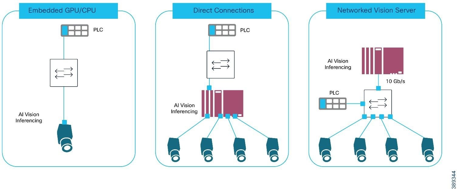 |
AI-Driven Machine Vision Deployment Models
Each of these models are supported in this solution and have their own sets of pros/cons related to them.
Table 1. Comparison of AI-Driven Machine Vision Deployment Models
|
|
Embedded |
Direct (Industrial PC-based analytics) |
Networked |
| Pros |
● Minimal latency of transferring the vision data from camera to analytics
● Minimal networking requirements by limiting bandwidth intensive traffic
|
● Bounded and low latency from camera to vision analysis platform
● Optimizable GPU for use of small number of cameras
● Share compute resources support small range of cameras (typically 2-6)
|
● Optimize GPU utilization based on the # of cameras and specific application requirements
● Reduce cable installation costs with 1 cable per camera for data, power and synchronization
● Scale more cameras for more use cases (for example, vision tunnels)
● Improved manageability with fewer distributed compute platforms
● Fewer devices to update with security and inferencing
|
| Cons |
● Expensive GPU limited to processing images from 1 camera, underutilizing the compute
● Vendor lock-in on the AI vision application
● More devices to update with security and inferencing updates
|
● IPC must be close to the cameras
● Cameras need multiple cables for power and data/synchronization
● Limited scale as IPC supports typically 2-6 cameras
● Higher likelihood of under-utilizing expensive compute
● More devices to update with security and inferencing updates
|
● Network must support the additional bandwidth requirements
● Network does add some latency and contention
● Added expense of industrial switch ports
|
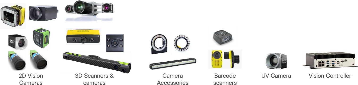
Machine vision systems are compromised by the following:
● Vision Cameras - there is a huge range of vision cameras and scanners for a variety of purposes including 2D scanning, 3D scanning, area scanners, line scanners, bar-code scanners, as well as UV and infrared cameras. The solution validation used a range of cameras from a variety of vendors
● Camera accessories such as lenses and lighting. In some cases, these may also be connected to provide controllability and power.
● AI-driven Image Processing & Analytics - the cameras require control and management, and their image data needs to be acquired and processed. There are a range of deployments of the images processing and analytics, including camera-embedded CPU/GPUs, specialized industrial PCs or time/bandwidth allowing server deployments locally or in the cloud.
● Historian and File storage – often the image from the cameras needs to be copied and stored for historical and traceability reasons. Additionally, the images may be used to update/train AI inference applications.
● Industrial networks to connect the camera, their accessories, and the image processing.
Machine Vision systems are also integrated into the Industrial Automation systems as their results of the image processing are taken into consideration in the automation process; for example, passing or failing a product or step, locating a key piece of data/information on packaging, or providing location/orientation of a product for robotic operations, among a few. All these components were tested in our validation lab.
 |
Machine Vision Traffic Types and Patterns
One of the biggest concerns with Machine Vision systems is the amount of data they produce and how that will impact the network and the other applications that rely on it. So, it is important to look at the traffic patterns that are involved. This section will describe the key traffic flows generated in each of the three deployment models described previously: embedded, directly connected and networked compute.
Before we look at the deployment models, we describe the type of traffic generated. Table 2 outlines the traffic types generated by machine vision systems.
Table 2. Machine Vision Traffic Types and Characteristics
| Traffic |
Description |
Traffic Type |
Characteristics |
| Precise Time Protocol (PTP) |
Often camera images must be taken at the precise moment and timestamped. The camera and application clocks are often synchronized with PTP |
UDP |
Layer 2 Uncast or Layer-3 UDP traffic. PTP is cyclically produced and latency/jitter sensitive. PTP produces two types of traffic events and general. Event traffic is more sensitive to packet delay and jitter. PTP typically generates minimal traffic load. |
| GigE Vision Discovery |
This part of GigE Vision establishes basic network connectivity with link negotiation, IP Address configuration and discovery & enumeration of other GigE Vision devices |
DHCP, UDP |
This traffic is not particularly latency/jitter sensitive or packet-loss sensitive and is only present at application/device startup |
| GigE Vision Control (GVCP) |
Allows an application to configure a device (e.g. camera) and set up the image streaming channels. It is also used to trigger image capture |
UDP 3956 |
This is typically low-bandwidth, latency-sensitive communication similar to industrial control protocols. Packet sizes are small. |
| GigE Vision Streaming (GVSP) |
Allows an application to receive (GVSP receiver) image data and information from a transmitter (GVSP transmitter) |
UDP |
GVSP is bandwidth intensive and its packets can be very large, often the maximum size supported by the network. GVSP is also latency/jitter sensitive as the images often need to be processed quickly for the industrial application GVSP has application-level mechanisms to handle potential packet loss |
| File Transfer |
Images often need to be collected and stored for traceability, model-training or for historical purposes |
FTP |
FTP traffic can be very bandwidth intensive, and packets sizes very large. But FTP is typically not latency/jitter or packet loss sensitive. |
| Industrial Protocols |
Often the camera or vision analysis application must signal to the industrial controller the results of the image analysis. Therefore, these devices often support Industrial Automation protocols like Profinet, CIP EtherNet/IP or Modbus. |
UDP or Layer 2 unicast |
Industrial automation and control protocols are low-bandwidth, latency/jitter-sensitive communications. Packet sizes are generally small. |
Machine Vision in the IA Architecture
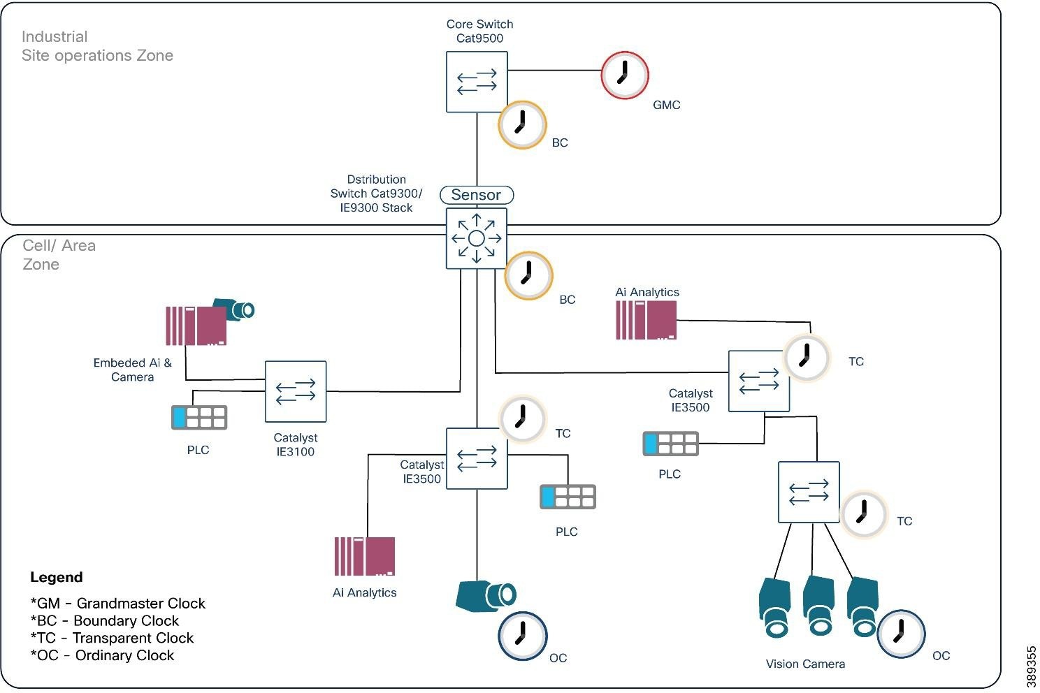
The Machine Vision architecture below shows how machine vision applications fit into a standard industrial automation network. The architecture supports the 3 machine vision deployment models.
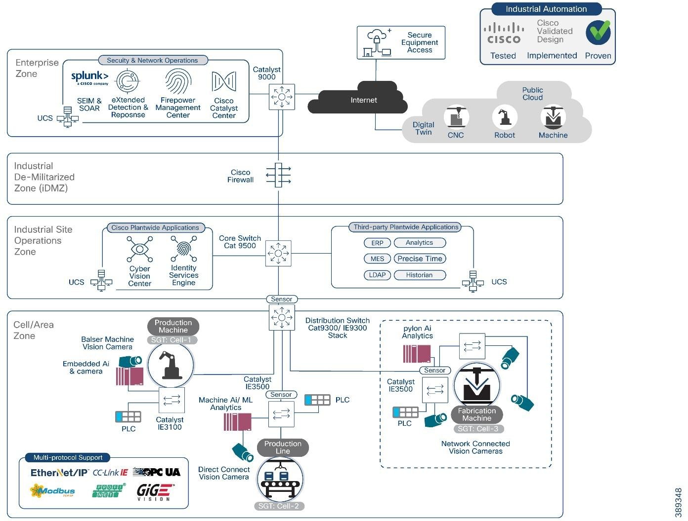 |
The machine vision solution adds the following to the Industrial Automation solution portfolio:
● Support for a range of machine vision cameras and AI/ML analytics software within the Industrial Automation architecture
● Support for the variety of deployment models; Embedded, Direct Connect and Network Connected
● Support for the key machine vision communication standard, GigE-Vision
● Rely on IE9300 and IE3100 series and add the IE3500 & IE3500H series switches to securely connect and power machine vision cameras
● Security tools and functions (Cyber Vision, TrustSec and Secure Equipment Access) to provide visibility and segment/protect machine vision systems components
Validated Hardware and Software
The following tables show the key components tested for this design and implementation guide.
Table 3. Cisco Infrastructure and Security Components
| Role |
Vendor |
Version |
Description |
| Industrial Access Switch |
Cisco |
IE3500 – IOS XE 17.18.x |
Aggregates cameras and industrial endpoints; supports PTP, QoS, and jumbo frames. |
| OT Visibility |
Cisco |
Cyber Vision 4.4 |
Provides deep OT asset and flow visibility. Supports industrial protocols. |
| Secure Equipment Access |
Cisco |
N/A |
Provides remote access |
| Distribution Switch |
Cisco |
Catalyst 9300 – IOS XE 17.15.x |
Distribution/access layer for cell area zone. PTP boundary clock. |
| Core Switch |
Cisco |
Catalyst 9500 – IOS XE 17.15.x |
High-performance aggregation/core. PTP boundary clock. |
Table 4. Vision Sensors or Smart Cameras
| Vendor |
Product ID |
Firmware |
Link Speed |
PoE |
Description |
| Cognex |
IS8912C |
25.2.0 (1456) |
1 Gbps |
Yes (at) |
In-Sight high-performance smart camera |
| Cognex |
DM290-BCC000 |
7.0.1 |
1 Gbps |
Yes (af) |
DataMan barcode reader |
Table 5. Vision Cameras
| Vendor |
Product ID |
Firmware |
Link Speed |
PoE |
Description |
| Basler |
a2A1920-165gm |
2.5.0 |
5 Gbps |
No |
High-speed area scan |
| Basler |
a2A1920-51gm |
2.5.1 |
1 Gbps |
Yes (af) |
Area-scan PoE |
| Basler |
r2L2048-58gm |
2.5.1 |
1Gbps |
Yes (af) |
Line-scan PoE |
| Basler |
R2L2048-172gm |
1.1.0 |
5 Gbps |
No |
5GigE line-scan |
| Cognex |
CIC-A12-CG-9-G |
20230801… |
1 Gbps |
Yes (af) |
Area-scan |
| Cognex |
CIC-A20-MG-27-5G |
2.5.2 |
5 Gbps |
No |
5GigE area-scan |
| Zebra |
CV60-A50SMG-0000W |
9.1.0.1 |
1 Gbps |
Yes (at) |
Area-scan |
| Zebra |
3580-4M20CG-0000W |
1.14.0 |
1 Gbps |
No |
3D vision sensor |
| Lucid |
TRI0515-C |
1.129.0.0 |
1 Gbps |
Yes (af) |
Triton area-scan |
| Lucid |
TRI02XA-M |
1.73.0.0 |
1 Gbps |
Yes (at) |
Triton line-scan |
Table 6. Vision Software
| Role |
Vendor |
Product |
Software Version |
Description |
| Vision Analytics |
Matrox |
Matrox Capture Works |
10.50.923 |
Acquisition & diagnostics tool |
| Vision Analytics |
Matrox |
Matrox Design Assistant |
9.1.54.0 |
Vision application builder |
| Camera SDK / Viewer |
Basler |
Pylon |
25.06.4.17077 |
Basler camera SDK & viewer |
| Camera SDK / Viewer |
Lucid Vision Labs |
ArenaView |
1.0.49.3 |
Viewer and control tool for Lucid cameras |
| Vision Suite |
Cognex |
In-Sight Vision Suite |
25.2.0 (680) |
Software for In-Sight 2D/3D cameras |
| Vision Suite |
Cognex |
In-Sight Explorer |
6.5.0 |
Legacy In-Sight camera configuration suite |
Table 7. Safety-Rated Controller and I/O Devices
| Role |
Vendor |
Description |
| PROFINET Controller (Safety-Rated) |
Siemens |
Siemens S7 PLC operating as the PN-IO Controller for the cell, participating in the PROFIsafe safety control loop. |
| PROFINET I/O Device (Safety-Rated) |
Siemens |
Siemens ET200 remote I/O stations running PROFINET + PROFIsafe, handling safety-critical I/O for machine operation. |
Table 8. PTP Timing Components
| Role |
Vendor |
Description |
| PTP Grandmaster Clock (GM) |
Meinberg |
LANTIME M600 operating as the network’s IEEE 1588-2008 / 1588-2019 PTP Grandmaster, providing deterministic time distribution for machine vision, controllers, and safety systems. Running firmware 6.24.020. |
Machine Vision Networking and Security Design
This section describes the industrial automation networking and security architecture tailored for the unique demands of AI-driven machine vision systems within industrial plant environments. The design focuses on securely integrating machine vision cameras and their AI analytical models to modern manufacturing networks.
At its core, this architecture aligns with the Purdue Enterprise Reference Model, specifically emphasizing the Cell/Area Zone (Levels 0-2) where machine vision cameras, lighting controllers, sensors, and Industrial PCs (IPCs) or edge servers reside. This zone is the operational heart of the plant floor, executing real-time control and data acquisition. Preserving smooth, continuous plant floor operations is paramount, necessitating a design that prioritizes security, segmentation, and availability as fundamental pillars.
The proposed solution extends Cisco's proven Industrial Automation network and security design principles to address the specific requirements of machine vision, such as high-bandwidth image streaming, precise synchronization, and low-latency processing. It provides a framework for secure, high-performance connectivity from the industrial edge to enterprise and cloud applications, facilitating AI/ML model training, historical data retention, and consolidated analytics.
There are three key areas focused on in this section:
● Vision System considerations look at key choices on how to connect camera, camera/analytics deployment modes, where to place the cameras and image analytics compute within the network and how to efficiently transfer the data coming from the camera.
● Network design recommendations include PoE, synchronization, Quality of Service, Jumbo Frame support, resiliency and more
● Security design recommendations include AAA, segmentation with TrustSec and Industrial Cyber Security applications
The successful deployment of machine vision systems hinges on careful consideration of how cameras connect, where analytics are processed, and how image data is transferred across the network. This section reviews:
● The camera connectivity options
● Considerations around the three Machine Vision deployment models; Embedded, directly connected and networked
Machine Vision cameras can connect to their analytics platforms via different media. Typically, machine vision cameras have options to be connected using Coax, USB and Ethernet. All three are still available, but this document recommends Ethernet options.
Ethernet competes with the other options in range and throughput but has a distinct advantage in supporting networking options as well as power and synchronization over the same cabling infrastructure. For most scenarios, Ethernet connectivity significantly reduces the cost of deployment and operations and provides significant benefits over the other connectivity options.
This solution focuses only on Ethernet connectivity. For example, cameras are reachable via a network for troubleshooting and maintenance. The following table lists characteristics and some of the pross/cons of each option.
Table 9. Comparison of Machine Vision Camera Connectivity Options
| Media Type |
Speed |
Distance |
Pros |
Cons |
| Coax, for example CoaxPress |
Up to 12.5 GB |
100 m |
● Reliable when in electrically noisy environments
● CoaxPress 2.0 delivers up to 37 watts of power
|
● Point to point connectivity
● Synchronization requires separate connections
● Requires special hardware (e.g. frame grabbers)
|
| USB |
Up to 80 GB with USB4v2 |
Less than 5 m, less for USB4 |
● Common technology
● Plug and play
● Easy to find expertise and options to install
|
● Very limited range for industrial applications
● Point to point connectivity
● More susceptible to interference
● Requires separate power and synchronization connections
|
| Ethernet |
Up 40 GB with Cat8 cabling |
100 m copper, 1000s m fiber |
● Common technology
● Easy to find expertise and options to install
● Flexibly to deploy cameras and analytics over larger areas
● Plug and play
● Supports highest amount of power (up to 90 watts)
● Synchronization via PTP on the same cable
● Supports networked connectivity
|
● Copper cabling may be susceptible to interference
|
Deployment of machine vision analytics
This section takes a deeper look at network considerations for the machine vision deployment models identified earlier. The three primary deployment models were identified:
● Embedded Analytics: In this model, the GPU/CPU for processing and analyzing image data is embedded directly within the camera. This offers minimal latency between image capture and initial processing. The network primarily handles control signals, configuration, and potentially aggregated results or metadata upstream.
● Direct Connect Analytics: An Industrial PC (IPC) equipped with a GPU/CPU and multiple network ports is directly connected to a small number of vision cameras. This approach keeps processing local to the cameras, suitable for applications requiring very low latency feedback, such as high-speed quality inspection. The network's role here is often limited to IPC management and forwarding processed results or summarized data.
● Networked Vision Server Analytics: This is the most common and scalable model where cameras connect via standard Ethernet switches to a centralized industrial or enterprise-grade PC/server/GPU for analysis. In this scenario, raw or partially processed image data traverses the network to the analytics platform. This model demands high-bandwidth, low-latency, and resilient network services to transport large volumes of vision data efficiently.
The placement of AI-driven image processing and analytics significantly impacts network design and performance requirements. This solution supports all three deployment models, but recognizes they have different impacts and considerations for the network as described in the table below:
Table 10. Network Impact of Machine Vision Analytics Deployment Models
| Model |
Where analytics occur |
Network Bandwidth impact |
Sensitivity to Network Latency/Jitter |
Network role |
| Embedded |
Inside camera |
Low |
Low |
Control + metadata + results |
| Direct Connect |
IPC directly connected to the cameras |
Low |
Low |
IPC mgmt + results |
| Networked Vision Server |
Remote IPC or Central server |
High |
High |
Real-time transport |
The choice of deployment model dictates requirements on the network capacity, latency tolerance, and security posture. For example, deploying a machine vision system in a brownfield scenario on network infrastructure with low-bandwidth support (such as 10/100 Mb access ports, 100/1000 Mb uplinks) may not be suitable for networked vision deployments or require separate/new network deployments. In this case an embedded or direct connect model may be cost justified.
This CVD primarily focuses on the Networked Vision Server model, as it presents the most complex and comprehensive networking challenges and opportunities for scale, flexibility, and cost optimization.
A key consideration for a machine vision system is the transfer of the image from the camera sensor to the vision analytics platform. The amount of data generated by the camera, the speed at which the image must be processed and the number of cameras involved will dictate the deployment model, such as where machine-vision analytics are executed.
From a network design standpoint, machine vision deployments fall into two fundamentally different architectures Embedded/Directly Attached or Networked analytics, each with distinct performance and determinism requirements.
The Embedded/Direct Attached model, the critical image transfer between camera and image processor occurs off the network. Images are transferred off the camera directly to an analytics engine, but often not with real-time processing considerations. From a network standpoint, images transferred off the camera or the IPC (in a directly-attached model) for historical retention/traceability and inference model training. Neither of which typically has real-time requirements but have bandwidth implications on the network.
In the Networked deployment model, the critical image transfer occurs on the network, typically using the GigE-Vision protocol, specifically streaming via GVSP. Unlike hard-real-time fieldbus protocols, GVSP over Ethernet has some tolerance to jitter, but the system (image acquisition + processing + PLC decision) usually does not. For a use case with a 40 ms time:
● Camera exposure and readout may consume 5–10 ms.
● Network transport must be bounded to a few milliseconds worst-case, even under bursts.
● Inference on GPU may consume 5–20 ms depending on the model.
● PLC signaling and actuator response consume the remaining budget.
Embedded / Direct-Attached Analytics (Local Inference at the Camera or IPC)
In this model, vision inference occurs inside the camera itself, in an embedded GPU module, or on a directly connected industrial PC. Because the image processing pipeline remains local, full-frame image transport across the network is minimized or optional. The network in this architecture primarily carries:
● Image analysis results signaled to PLCs or SCADA systems using:
◦ PROFINET
◦ EtherNet/IP (CIP)
◦ Modbus/TCP
● Camera management and configuration communication
● Inspection metadata (such as pass/fail, measurement values, bounding boxes)
● Periodic full-frame exports for:
◦ Historian / traceability
◦ Offline analysis
◦ AI model re-training
◦ Quality audits
Implications for Network Design:
● Bandwidth utilization: Typically low, except during historian uploads; these flows are not latency or packet-loss sensitive and are sent with File-Transfer Protocol (FTP), which accommodates re-transmissions.
● Latency & jitter considerations apply only to control traffic (such as Profinet or CIP) not image transfer.
● QoS is necessary to protect PLC and trigger traffic from engineering or historian burst transfers.
● In this architecture, image data does not traverse the network prior to processing.
Real-World Example: Process Quality Cameras (Metadata-Driven Analytics)
In a discreet-manufacturing line, several process-quality cameras monitor critical process steps.
Each camera runs an embedded AI model evaluating anomalies and inefficiencies during the cycle, such as material usage deviations, assembly timing drift, or irregularities in motion.
● Each camera publishes metadata only (no continuous image streaming) to a supervisory server, coordinating camera operations.
● Cameras exchange metadata with one another to build an on-the-fly 3D context of the process (without sending raw frames).
● The supervisory server receives low-bandwidth inference results to update dashboards or trigger alerts.
● If something unusual happens, operators can pull a replay clip stored locally on the camera for non-real-time review.
Network implication:
Bandwidth demand remains low in this model, with only on-demand non-real-time streaming. However, POE requirements increase, and in some cases, switches must provide PoE++ to reliably operate CPU/GPU-equipped smart cameras. QoS is still recommended to protect other automation and control traffic.
Real-World Example: Local Analytics with Historian Offload
A camera conducts go/no-go inspection and stores all frames locally. For regulatory or traceability reasons, it exports frames of defective products/parts or all frames (full traceability mode). These exports may be bandwidth-heavy (hundreds of Mbps to multi-Gbps), but they do not influence real-time inspection, and they may be rate-limited or scheduled during low network traffic periods.
Network implications:
High-bandwidth, non-deterministic transfers are expected when archiving images or exporting full-frame data, but inspection results themselves must be communicated with strict reliability to ensure downstream PLC actions remain accurate and timely. The network also provides stable PoE/PoE++ delivery to power cameras. QoS is still recommended to protect other automation and control traffic.
Networked Vision Analytics (Image Transfer Over the Network)
When image processing is executed remotely, on a centralized GPU server or edge compute server, the full image stream must traverse the network. In this model, the network becomes a critical component in the real-time image inspection loop. Machine vision introduces traffic patterns that are fundamentally different from traditional OT control protocols. For example, high-resolution GigE Vision cameras generate continuous or burst-based UDP streams that are sensitive to loss but tolerate some latency (often in the microsecond-scale). Unlike cyclic industrial protocols (CIP, PROFINET), which are small, time-bounded, and expected to be lossless, GigE Vision (GVSP) image streams contain hundreds or thousands of large packets per image frame. Loss of packets or significant delayWeWeWEB can result in frame corruption, mistaken image analysis and/or a failed inspection cycle.
GigE Vision Image Transfer Requirements:
● GigE Vision Streaming Protocol (GVSP) is the data plane of GigE Vision, responsible for delivering raw or partially processed image data from the camera to a host. Key characteristics of GVSP include:
◦ UDP-based, extremely bursty
◦ Highly loss-sensitive where many deployments treat unrecovered packet loss as a lost or unusable frame.
- Note: Some vendors support limited application-level retransmissions, but these increase latency and are only viable within the application timing windows. In practice, the network must behave as near loss-free under burst load.
◦ High bandwidth demand where modern connectivity speeds and camera technologies generate sustained and burst traffic patterns such as:
- 1 Gb/s for basic single-camera inspection
- 2.5–5 Gb/s for high-resolution sensors
- 10+ Gb/s for multi-camera cells, fast conveyors, or robot-guided inspection
◦ Aggregated bandwidth must be supported to support multiple cameras to a destination
◦ Jumbo Frames support which reduces fragmentation and overhead with 9000-byte MTU (Maximum Transmission Unit) recommended. This feature must be end-to-end consistent across cameras, switches and server/compute stations.
◦ Low latency and jitter are ideal to ensure stable inference cadence, reliable multi-camera fusion, consistent sequencing of frames and timely feedback to PLCs. To contrast, high jitter can lead to delayed or mis-analyzed images and inconsistent defect detection.
● GVCP is the control plane of GigE Vision and operates over UDP port 3956. It is responsible for device discovery, camera configuration, stream negotiation, network parameter tuning, heartbeats, and software trigger or “action” commands used for multi-camera synchronization. Key characteristics include:
◦ Small packets sizes but may be highly latency-sensitive; typical GVCP messages range from tens to a few hundred bytes.
◦ Most implementations do not retry or tolerate delayed control messages — especially trigger and action commands used to coordinate frame capture across multi-camera cells.
◦ Excessive latency or jitter can break deterministic sequencing of camera triggers, exposure timing, and timestamp alignment — leading to missed triggers, desynchronized multi-camera capture, or invalid image processing pipelines.
◦ Bursty behavior during camera initialization (camera discovery, stream establishment, register reads/writes) followed by low-rate periodic control traffic during streaming (heartbeats, status, events).
◦ Control-plane criticality: GVCP must be treated as high-priority traffic with minimal queuing, consistent forwarding, and fast convergence to ensure stable multi-camera operation.
● Engineering flows: model deployment, tuning, user tools, usually occurring outside of production processing
● Historian transfers: large but non-critical, which may occur during production cycles
Example: Networked Analytics (Conveyor Bottle Inspection)
A high-speed beverage line inspects bottles for cap alignment and fill level accuracy. Workflow:
1. A photoelectric sensor triggers a GigE Vision camera as each bottle passes.
2. The camera sends full-frame GVSP data to a centralized GPU server.
3. The GPU executes inference within a narrow time budget.
4. A rejector downstream must eject defective bottles, typically within 20–40ms of detection.
Critical behavior:
● Only a small queue of pending images is allowed; inference must be faster than acquisition.
● Missed or corrupted frames result in the bottle failing inspection (no second chance).
● Frequent retransmission events or network jitter increase inference time.
● If the average processing time exceeds acquisition rate, the queue overflows → bottles are missed → catastrophic line failure.
Network implication:
The network is part of the real-time control loop and must support lossless, deterministic GVSP transport.
Table 11. Comparison between embedded vs networked analytics
| Attribute |
Embedded / Direct-Attached Analytics |
Networked Vision Analytics |
| Where inference runs |
Camera or IPC |
Central GPU server |
| Network load |
Low (metadata + occasional full frames) |
High (continuous GVSP streams) |
| Real-time dependency |
Network is NOT part of real-time imaging pipeline |
Network IS part of real-time imaging pipeline |
| Bandwidth sensitivity |
Low except historian offload |
Extremely high (hundreds of Mbps to multi-Gbps) |
| Latency & jitter |
Only affects PLC/control traffic |
Directly affects frame sequencing & rejector timing |
| Reliability needs |
Moderate |
Critical (near-lossless GVSP transport) |
| QoS needs |
Protect PLC + control plane |
Protect PLC/control, Strict GVSP prioritization + congestion isolation |
| Jumbo frames |
Optional |
Strongly recommended end-to-end (9000 bytes) |
| Failure impact |
Local retries, minimal production risk |
Frame loss → failed inspection |
Network Design Recommendations
Although machine vision systems typically are deployed at the edge and inside the Cell-Area zone of the Purdue Control hierarchy, as we have described previously, they have distinctly different impacts and requirements on the network. Here is a summary of the key network design recommendations for machine vision systems covered in this section:
Table 12. Network Design Recommendations
| Recommendation |
Reasoning |
| Depending on application, use high-bandwidth network infrastructure that supports multiple 10 Gb interfaces for uplinks and image processing connectivity and 1 Gb or 2.5 Gb interfaces for camera connectivity |
Machine vision cameras are equipped with high connectivity options and generate more granular images at higher speeds requiring more bandwidth |
| Use PoE capable switches to power machine vision cameras with the right level of PoE capabilities |
PoE reduces the complexity and cost associated with separately powering machine vision cameras |
| Use QoS policies that prioritize PTP, Industrial Automation and Control traffic (such as CIP or Profinet) and vision control and management (such as GVCP) |
Machine vision streaming traffic can introduce significant jitter and bandwidth utilization that may negatively impact critical control traffic without a QoS policy |
| Consider use of Precision Time Protocol (PTP) to synchronize multi- camera systems to their controller or correlate events over using direct I/O links to trigger the cameras |
Many machine vision systems need tight coordination for camera image taking. PTP is a tested and tried mechanism and provides a mechanism to precisely trigger cameras images and to time-stamp those images for historical/traceability. Using PTP (vs. I/O links) reduces the amount of cabling that needed to be deployed without sacrificing precision |
| Use network infrastructure that supports jumbo frames for GVSP wherever supported and configure MTU consistently. |
Jumbo frames significantly reduce the number of packets needed to transfer an image frame over the network. Jumbo frames significantly reduce the latency needed to transfer a frame. |
| Place cameras and GPU/IPC servers on the same L2 domain/VLAN |
Cameras management applications typically use broadcasts to discover cameras |
| Use dedicated VLANs for machine vision system |
Limits the broadcast domain |
| Engineer uplink capacity based on worst-case aggregate camera throughput plus 30% headroom. Size uplinks based on worst-case combined camera throughput, not only nominal frame rates. |
Ensure good network performance and avoid bottlenecks that may impact vision traffic latency/jitter and potentially other traffic |
| Keep switch hop count low in the vision path. |
The number of hops increases latency/jitter to transfer frames and increases the opportunity for bottlenecks in the network to form |
This section outlines the solutions key network design considerations, including
● Bandwidth
● Power-over-Ethernet
● Prioritization and Quality of Service
● Latency and Jumbo Frame support
● Resiliency
● Other industrial network considerations, such as DHCP
Modern machine vision cameras typically can generate granular images very quickly. Typically, cameras have 1-10 Gb links and generate images with 10s to 100s of megapixels, and those are expected to increase as the vision sensor technology improves. But just because a camera connects a 1Gb, it likely does not need that bandwidth consistently. Nonetheless, a key consideration for networking machine vision applications is the speed and bandwidth of the network.
Therefore, the recently announced IE3500 and IE9300 series switches are good candidates for machine vision applications. Both support all 1Gb and some 2.5 Gb access ports with a range of 2-4 10Gb ports for uplinks and/or connectivity to networked IPCs processing images in a multi-camera deployment.
Following are a depiction and table of IE switches well suited supporting high-bandwidth and PoE requirements of machine vision cameras. Other IE switches support high-bandwidth access and uplink ports and would be suitable for these applications.
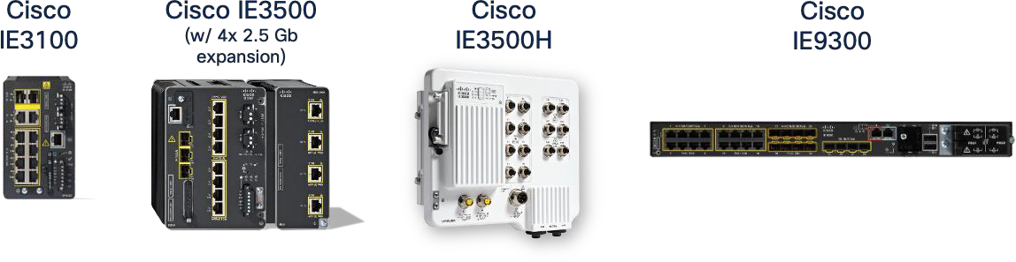 |
Industrial Ethernet (IE) 9300, 3500 and 3100 switches
Table 13. IE Switches for Machine Vision cameras
| IE Switch Family |
10 Gb Ports |
2.5 Gb Ports |
1 Gb Ports |
Selection Guidance |
| IE3500 |
3 |
0/4 |
8/24 |
Greenfield deployments of high-bandwidth, high-power cameras for network connected deployments |
| IE3505 |
- |
0 |
11/27 |
Greenfield deployments of high-power cameras (e.g. Embedded cameras) |
| IE3500H |
2 |
2 |
12 |
Greenfield deployments of high-bandwidth, high-power cameras for network connected deployments |
| IE9300 |
4 |
8 |
16 |
Greenfield deployments of high-bandwidth, high-power cameras for network connected deployments |
| IE3400 |
0 |
0/4 |
10/26 |
Brownfield support for PoE-capable cameras with limited uplink capacity for embedded or directly-attached deployments |
| IE3300 |
2 |
0/4 |
10/16 |
Brownfield and Greenfield deployments of high-bandwidth cameras for network connected deployments |
| IE-3100 |
- |
- |
10 |
Brownfield support for PoE-capable cameras with limited uplink capacity for embedded or directly-attached deployments |
Power-over-Ethernet (PoE) is a critical design consideration for machine vision deployments in the Cell/Area Zone, offering significant operational benefits by simplifying infrastructure and reducing deployment and cabling costs.
Operational benefits:
● Simplified Cabling and Reduced Costs: By delivering both data and power over a single Ethernet cable, PoE significantly reduces the amount of cabling required. This translates directly to lower material costs, faster installation times, and reduced labor, especially beneficial in brownfield deployments or when modifying existing lines. For machine vision, this can mean reducing the required cables from three (power, data, synchronization) to just one.
● Flexible Device Placement: Eliminating the need for separate power outlets near each camera or accessory provides greater flexibility in device placement. This is crucial for optimizing camera angles and coverage in complex industrial layouts, allowing cameras to be positioned precisely where needed, even in areas without readily available power infrastructure.
● Centralized Power Management: Power can be managed centrally from the PoE-enabled industrial switch. This simplifies power cycling, monitoring, and troubleshooting of connected devices. Network administrators can remotely power cycle a camera, for instance, without needing physical access, improving operational efficiency.
The following table shows PoE capabilities on the Cisco Industrial Switches.
Table 14. PoE Capabilities of Cisco Industrial Switches
| Platform |
Total PoE Ports (Max) |
90W / 4-pair PoE Ports |
Supported PoE Types |
Max PoE Budget |
Expansion Options |
Selection Guidance |
| IE3500 / IE3505 |
Up to 24 (8 base + modules) |
Up to 8–12 depending on module combination |
PoE, PoE+, UPOE (60W), 4-pair PoE (90W) |
360–480 W |
IEM-3500 family (PoE+/UPOE/4- pair) |
Select for high-density PoE, mixed 30W/60W/90W, and modular growth |
| IE9300 |
Up to 24 total PoE ports |
8 ports (the 2.5 G mGig ports only) |
PoE, PoE+, 4- pair PoE (90W on 8 mGig ports) |
480–720 W |
None |
Select for high-density PoE+ and exactly 8 ports of 90W for high-power loads |
| IE3100 |
4–8 |
0 - 2 Depending on the SKU |
PoE, PoE+, 4- pair 90W (model dependent) |
120-240 W Depending on the SKU |
None |
Select for compact PoE+ where size and simplicity matter |
| IE3300 |
Up to 12 |
4 ports (via IEM-3300-4MU) |
PoE, PoE+, 4- pair PoE (90W on module only) |
Up to 480 W |
IEM-3300-4MU |
Select for existing installations, use existing hardware |
| IE3400 |
Up to 16 |
— |
PoE, PoE+ |
240–480 W |
IEM-3400-8P |
Select for existing installations, use existing hardware |
| IE3200 |
8 |
— |
PoE, PoE+ |
~240 W |
None |
Select for existing installations, use existing hardware |
| IE3500H / IE3505H (IP67) |
8–16 |
— |
PoE, PoE+ |
240 W |
None |
Select for IP67 harsh environments when PoE+ is needed. |
| IE3100H (IP67) |
non-PoE |
— |
— |
— |
None |
It does not support PoE use cases |
| IE3400H (IP67) |
non-PoE |
— |
— |
— |
None |
It does not support PoE use cases |
Important PoE notes
● PoE capabilities vary by SKU. Not all models in a product family support PoE. PoE features are available only on SKUs explicitly labeled with “P”, “UP”, or “PoE”. Always validate SKU-specific PoE before selecting the platform.
● Check for SKUs and ports that support 4-pair / 90W PoE.
● Expansion modules increase PoE ports but share the same power budget. Adding PoE modules does not create a separate power pool; all PoE ports (base + module) draw from the same system PoE budget defined by Power Supply Unit (PSU) selection.
Cisco IE3500 PoE Capabilities
The Cisco IE3500 Rugged Series switches offer comprehensive PoE support, making them a perfect choice for powering machine vision cameras and associated accessories. IE3500 enables dense deployments of cameras and lighting controllers without the need for additional power infrastructure.
PoE Budget Planning and Calculation
Correct PoE budgeting is essential to ensure that a switch can support the expected number and type of Powered Devices (PDs) throughout its operational lifetime. PoE design must account for the total power delivered to PDs as well as the internal power required to operate the switch hardware itself. If the total required power exceeds the PSU capabilities, the switch may be unable to power all PDs, enforce prioritization, or operate safely under full load.
For all industrial switches, Cisco publishes three categories of values in the hardware datasheet that are required for PoE planning:
● Base Switch Power Consumption: The power required for the platform hardware to operate (excludes PoE delivered to PDs).
● Expansion Module Power Consumption: Additional internal power draw introduced by any installed IEM modules.
● Power Supply Options: The maximum power available to the system from the selected PSU.
These three inputs define the usable power available for PoE. The calculation is:
Available PoE Power = PSU Wattage - (Base Switch Power Consumption + Expansion Module Power Consumption)
● When designing the installation, confirm the exact values in the datasheet for the specific base model and expansion module being deployed.
● PoE budgets vary by SKU, and only a subset of models supports PoE.
● The total consumption of attached PDs (based on their PoE class or nameplate rating) must not exceed the available PoE power.
● A margin should be reserved for environmental tolerance and future additions.
Example Scenarios for PoE Budget Calculation (using IE3500 Datasheet Values):
The following examples illustrate how to apply the budgeting method. Every deployment must reference the power tables for the exact SKUs in use.
Table 15. Examples of PoE Budget Calculation
| Scenario |
Configuration |
Base Switch Power |
Module Power |
PSU Wattage |
Available PoE = PSU - (Base + Module) |
| A |
IE-3500-8P3S (no expansion), 240W PSU |
32W |
0 W |
240 W |
240-32 = 208 W |
| B |
IE–3500-8P3S + IEM-3500-8P, 240 W PSU |
32W |
12 W |
240 W |
240-(32+12) = 196 W |
| C |
IE-3500-8P3S + IEM-3500-8P, 480 W PSU |
32W |
12 W |
480 W |
480-(32+12) = 436 W |
Design Guidance for PoE Budgeting:
● The datasheet power values must always be used for PoE planning. They reflect the actual hardware consumption of the selected switch and module SKUs.
● Expansion modules increase internal power consumption, reducing the PoE power available unless a larger PSU is installed.
● The PoE budget is shared across all PoE ports, including those on the base unit and any PoE-capable expansion modules.
● When designing for PoE+, UPoE, or 4PPoE 90W loads, sum the worst-case PD consumption and ensure it fits within the calculated PoE budget with an appropriate margin.
Calculating Power Requirements for Connected Devices
● Device Consumption: Obtain the maximum power consumption (in Watts) for each machine vision camera, lighting controller, or other PoE-powered device from the manufacturer's specifications. Always use the maximum stated consumption, not average, to account for peak loads.
● Cable Loss: Account for power loss over longer Ethernet cable runs. While often small, it can become significant for high-power devices over maximum cable lengths (100m).
● Total Required Power: Sum the maximum consumption of all Powered Devices (PDs) planned for connection to a single IE3500 switch, plus the system's own power consumption (base switch + any installed expansion modules + any uplink modules).
● Switch Power Budget: Compare the total required power against the total PoE power budget of the selected IE3500 model. This budget is typically specified in Watts (such as 240W, 480W) and represents the maximum power the switch can deliver across all its PoE-enabled ports.
● Headroom: Always design with a headroom above the calculated total required power. This accounts for future expansion, unexpected power spikes, and ensures stable operation.
● Monitoring: Use the show power inline command on the IE3500 CLI to monitor real-time power consumption per port and the overall switch budget. This helps validate calculations post-deployment.
Advanced PoE Features
● Perpetual PoE: Use Perpetual PoE on ports where a powered device reboot would disrupt operations. Power remains during switch reloads, allowing devices to stay up and ready when the switch returns. Note that Perpetual PoE preserves power, not traffic; it prevents powered device reboots during switch reloads so the device is already up, and data transmission resumes as soon as the switch returns.
● Fast PoE: Use Fast PoE so powered devices receive power immediately after a switch power-up. This minimizes recovery time for critical endpoints that must boot quickly after outages.
Considerations for PoE Expansion Modules
● Expansion modules share the same PoE budget pool as the base system, meaning high-power devices on expansion ports can reduce the available power for base-system PoE ports.
● PoE modules are supported only when installed on base systems that include native PoE hardware support.
● PoE modules cannot be used with non-PoE base systems, even if the deployment does not require PoE on any port. The chassis must provide the internal PoE power architecture for the module to operate.
● IEM-3500 PoE expansion modules are supported exclusively on IE3500 and IE3505 base systems. They cannot be installed on IE3300, IE3400, or other IE platforms.
Setting PoE Limits per Port
● To prevent oversubscription of the switch's total power budget and to allocate power efficiently, it is highly recommended to configure explicit power limits on individual PoE ports.
● Use the power inline consumption <watts> command in interface configuration mode to set a specific maximum power allocation for a connected device. For example, power inline consumption 30000 (for 30W).
● Alternatively, power inline auto max <watts> can be used to allow the switch to negotiate power but cap it at a specified maximum.
● This ensures that if a device attempts to draw more power than expected, or if a faulty device tries to draw excessive power, it will not negatively impact other critical devices or exceed the switch total budget.
Additional Design Considerations
● Cable Type and Length: Ensure the use of appropriate Ethernet cable types (such as, Cat5e or higher) that meet the distance and power delivery requirements for PoE. Longer cable runs can lead to voltage drop, impacting power delivery, especially for high-power devices.
●
● High-Power Strobes and Accessories: While the IE3500's 4PPoE/PoE++ capabilities are robust, some specialized, exceptionally high-power strobes or lighting systems may still exceed the per-port PoE budget. In such cases, these devices will require a separate power supply. Plan for these exceptions during the design phase.
● Environmental Factors: Ensure the IE3500's operating temperature range and environmental ratings are suitable for the specific industrial environment where it will be deployed. Operating near its maximum PoE capacity can generate heat, which needs to be managed within the industrial enclosure.
● Redundancy for Power: While the IE3500 provides power to end devices, consider redundant power supplies for the switch itself to enhance overall system availability and mitigate the risk of a single power supply failure affecting multiple critical vision components.
In high-speed machine vision systems, every captured frame directly influences critical decisions such as accepting or rejecting parts, aligning components, or stopping processes. For these decisions to be accurate, all cameras must capture images at the exact same instant—often down to the microsecond—not just approximately aligned.
Traditional methods like free-running clocks, software timers, or PLC trigger wires cannot guarantee this precision due to factors like clock drift, temperature variations, and uneven cable lengths. These small timing offsets can cause significant issues, including:
● Inconsistent measurements
● Mismatched views that disrupt 3D reconstruction
● Inspection logic errors caused by cameras firing at different times
Precision Time Protocol (PTP) provides a shared, highly precise timebase for all devices in the system—cameras, illumination, encoders, inference servers, and PLCs. Instead of each device having its own approximate time, all devices agree on the exact time with nanosecond-level accuracy. This common clock enables capabilities that traditional wiring cannot match.
Key Benefits of PTP in Machine Vision
● PTP provides a shared, precise timebase that allows cameras, controllers, illumination, and motion devices to operate on the exact same timeline which is critical as production speeds increase and multi-camera systems become standard.
● Deterministic, timestamp-based exposures: Cameras image capture is triggered at a specific PTP timestamp rather than when a packet or I/O signal arrives. This eliminates drift, jitter, temperature effects, and OS scheduling delays, ensuring all cameras capture the same moment for stereo depth, multi-view correlation, 3D reconstruction, and high-speed inspection of moving objects.
● Elimination of hardware trigger wiring: Traditional vision systems rely on discrete PLC outputs, which introduce cost, complexity, wiring bottlenecks, cable-length skew, and electrical noise. PTP with GigE Vision Scheduled Action Commands removes the need for physical trigger lines by coordinating all cameras through a single network-based multicast message, simplifying integration and scaling.
● Precise alignment with motion: PTP enables cameras to trigger exactly at specific positions in the motion cycle (for example encoder counts, robot joint angles, torque signatures, or illumination windows) resulting in consistent, blur-free images at high speed.
● Consistent and reproducible inspection decisions: With a unified time source, cameras, PLC logic, inference servers, and illumination align their understanding of events, making correlation straightforward and ensuring results remain consistent across runs and machine states.
● System-wide traceability: Every frame carries a synchronized timestamp, supporting MES and historian correlation, product genealogy, digital twin accuracy, and reliable root-cause analysis.
● Sub-microsecond synchronization accuracy: IEEE 1588v2 PTP delivers sub-µs alignment across cameras, controllers, and switches, enabling stable timing even as network load varies.
● GigE Vision 2.0 integration: Cameras use PTP to synchronize their internal clocks and trigger exposures precisely through Scheduled Action Commands. This eliminates wiring complexity, simplifies multi-camera scaling, and ensures all images correspond to the same instant.
Action Commands vs. Scheduled Action Commands
GigE Vision cameras can be triggered over the network using “action commands.” At a basic level, an Action Command is simply a packet that tells the camera: “Trigger now.” This allows a controller, PLC, or vision server to initiate image capture without discrete wiring. Early GigE Vision systems relied heavily on action commands because they were easier to integrate, especially when replacing hardware trigger lines
However, action commands inherit the timing limitations of Ethernet itself:
● Packet arrival time varies with network load
● Jitter and queueing delays affect when the camera receives the command
● Different cameras may receive the same command at slightly different times
As a result, cameras may not fire simultaneously. This may be acceptable for low-speed or non-critical applications, but it becomes a major limitation in modern machine-vision cells where objects are moving at high speed, 3D reconstruction requires synchronized views, or multiple cameras must capture the same instant.
To solve this, GigE Vision 2.0 introduced Scheduled Action Commands, which use PTP to achieve hardware-level deterministic triggering and image capture. A scheduled action command tells the camera to trigger at a precise future PTP timestamp (for example, 12:34:56.123456789). Cameras, synchronized to the PTP clock, wait internally and trigger exactly when their clock reaches that timestamp, regardless of packet arrival time. This enables perfect multi-camera alignment.
Table 16. Comparison of GigE Vision Action Commands
| Aspect |
Action Command |
Scheduled Action Command |
| How it Works |
“Trigger now”: camera fires when packet arrives. |
“Trigger at time T”: camera fires at a precise future PTP timestamp. |
| Timing Dependency |
Depends on network latency and jitter. |
Depends on PTP-synchronized clock, not network jitter. |
| Multi-Camera Sync |
Not simultaneous — each camera receives packet at a different time. |
Perfect sync — all cameras fire at the same timestamp. |
| Required Network Elements |
Any Ethernet network; no timing features needed. |
PTP domain, Transparent/Boundary Clock switches, PTP-capable cameras. |
| Determinism |
Low — varies with congestion and queueing. |
High — hardware-scheduled, sub-µs precision. |
| Best For |
Basic or low-speed capture. |
High-speed inspection, 3D reconstruction, multi-camera timing. |
PTP Components and Clock Roles
Machine vision deployments use the standard PTP hierarchy:
● Grandmaster Clock (GM): The primary time source, often a Level 3 device with GPS/IRIG input.
● Boundary Clocks (BC): Core or distribution switches that synchronize upstream and provide time downstream.
● Transparent Clocks (TC): Access layer switches (such as IE3x00, IE3400, IE3500) that forward PTP packets while correcting for residence time delays.
● Ordinary Clocks (OC): End devices such as cameras, vision servers, and PLCs.
● PTP uses the Best Master Clock Algorithm (BMCA) to elect the optimal GM based on priorities and quality.
Design Guidance
● Deploy plantwide PTP as the recommended architecture so all cameras, PLCs, motion systems, servers, and MES/historian tools share the same authoritative time source across the entire factory.
● Use centralized, redundant Grandmaster clocks at the industrial core (GPS-disciplined or high-accuracy NTP→PTP translation). This ensures stable timing and prevents devices from drifting into free-running mode during topology changes that can cause disruptions of time variations.
● Implement Boundary Clocks in core and distribution switches to regenerate timing downstream and scale the PTP implementation. Boundary clocks act as a buffer for Grandmaster or higher-level boundary clock by processing lower clock’s PTP communications.
● Use Transparent Clocks at the access layer so residence time is corrected on every L2 hop, maintaining sub-microsecond accuracy even under load.
● Treat PTP as control-plane traffic: apply strict QoS prioritization and minimize path asymmetry.
● Validate redundant paths and failover behavior: poor-quality GMs or disappearing GMs cause devices to revert to free-running mode, degrading multi-camera alignment and breaking Scheduled Action Command determinism.
● Use plantwide time distribution for environments that require accurate timestamps for MES correlation, historian logging, alarms, digital twins, security audits, and AI/ML analytics.
● Local (cell-only) PTP domains are acceptable only when timing accuracy matters only within the cell and no plantwide timestamp correlation is required. If used, domains must be strictly isolated through PTP filtering, domain separation, or blocking PTP on uplinks.
● A PLC or camera serving as a local GM can provide relative time but it is not recommended when high-accuracy plantwide alarming, logging, or multi-zone analytics are required.
 |
Limitations and Considerations
● PTP is not supported on 2.5G ports.
● PTP is not supported over links configured with TrustSec inline tagging.
● Careful network design is required to maintain PTP accuracy, especially in complex or redundant network topologies.
PTP Validation Results
Plantwide PTP behavior was validated using a Meinberg Grandmaster and logger while driving traffic through the Cell/Area Zone. The distribution layer operated as Boundary Clocks, with three IE switches functioning as Transparent Clocks. Even under deliberate GVSP congestion, the measured offset remained within ±0.1 µs and path-delay variation stayed below 0.15 µs.
This demonstrates that Cisco’s hierarchical PTP design (GM → BC → TC) maintains sub-microsecond accuracy across multiple hops and under load, ensuring reliable multi-camera synchronization and consistent Scheduled Action Command timing.
Machine vision traffic introduces unique patterns that differ significantly from traditional industrial I/O. When multiple source ports send toward a single destination at the same time, the destination port can become congested with the amount of traffic arriving from multiple sources.
Even when congestion does not occur, a converged network forwards traffic of different priorities where high-bandwidth image streams must coexist with control, safety, synchronization, and discovery traffic, each with distinct delivery requirements. A robust QoS model must ensure:
● Consistent, predictable latency for real-time control and synchronization traffic.
● Integrity and minimal packet loss for high-bandwidth image streaming.
● Isolation of background and non-critical traffic to prevent interference with operational flows.
● Consistent scheduling behavior across all switches along the traffic path.
A successful QoS design maps each traffic type into dedicated classes with appropriate scheduling, buffering, and drop policies applied end-to-end.
The following sections break down the traffic types present in a machine-vision cell and how each behaves under a QoS design.
Traffic Types in a Machine Vision Cell
A machine-vision-enabled Cell/Area Zone carries several distinct categories of traffic. Each behaves differently and must be treated accordingly by the QoS model.
Table 17. Machine vision cell traffic examples and behavior
| Type |
Examples |
Characteristics |
| Real-Time Industrial Control and Synchronization Traffic |
● Real time IACS traffic such as CIP implicit I/O, PROFINET RT
● Safety I/O
● PTP synchronization traffic (event and general messages)
● Vision control and management flows such as GVCP (discovery, configuration, and command messages)
|
● Small, cyclic or event-driven packets
● Extremely sensitive to jitter and delay
● Must be forwarded ahead of all other classes
● Forms the highest priority category in the QoS de
|
| Image Streaming Traffic (GVSP) |
High-bandwidth flows carrying image payloads from cameras to vision servers |
● Often uses jumbo frames
● Frequently bursty based on trigger rate Sensitive to packet loss (dropped frames reduce inspection accuracy)
● Requires predictable forwarding behavior, but must not delay control
|
| Background and Non-Critical Traffic |
● File transfers and backup operations such as FTP/SFTP image offload
● Image archiving for compliance, documentation, or AI training
● Remote management, diagnostics, and log retrieval
● Firmware updates, remote access sessions, and analytics ingestion
|
● Delay-tolerant
● Not operationally time-sensitive
● Should never compete with real-time or GVSP flows
● Ideal candidates for best-effort treatment
|
QoS Design
Cisco QoS uses a toolset to provide the priority and preferential treatment for the IACS traffic. The key tools used across the platforms for this version of Industrial Automation are:
Classification and Marking—Classifying or marking the traffic as it enters the network to establish a trust boundary that is used by subsequent QoS tools, such as scheduling. Class maps and policy maps are the mechanism to provide the network classification.
Policing and Markdown—Policing tools, known as Policers, determine whether packets are conforming to administratively-defined traffic rates and take action accordingly. Such action could include marking, remarking, or dropping a packet.
Queuing and Scheduling—The network infrastructures determine how a frame or packet exits a device. Whenever packets enter a device faster than they can exit it, such as with speed mismatches, then a point of congestion or bottleneck can occur. Devices have buffers that allow for scheduling higher priority packets to exit sooner, which is commonly called queueing.
Note: Policing and Markdown are not used in the QoS design for IACS or GigE vision traffic as we do want to impact control traffic. If rate enforcement is necessary, it should be applied to background flows only.
The diagram that follows summarizes how Cisco IE3500/IE9300 switches apply trust, classification, marking, and scheduling to implement the QoS model end-to-end.
● At Ingress (incoming traffic): Trust, Classification, and Marking occur. Traffic is identified, categorized, and assigned QoS values to define its priority.
● At Egress (outgoing traffic): Queuing and Scheduling manage the marked traffic. Priority Queues (PQ1, PQ2) handle critical traffic, while Weighted Round Robin (WRR) distributes bandwidth proportionally for other classes. The overall egress process is governed by Cisco's SRR/SPA mechanisms, ensuring efficient and prioritized delivery.
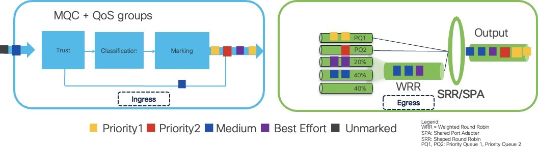 |
Classification and Marking Strategy
Traffic classification should be performed at the access switch, where cameras, PLCs, sensors, IPCs, and servers connect to the network. This establishes a clear trust boundary.
Key Principles:
● Do not trust markings from end devices unless explicitly validated (for instance CIP and Profinet devices).
● Most cameras (GigE Vision) do not mark DSCP, so switches should classify their traffic using ACLs.
◦ GVCP control traffic uses a well-known UDP port (typically UDP 3956 → control).
◦ GVSP streaming traffic uses known destination IPs and in the case of some vendors standard ports (For example, Basler cameras use source UDP port 49152 for GVSP).
● PTP event and general messages must be placed in the highest priority class.
● GVCP and GVSP should be marked into a non-standard DSCP value to ensure predictable treatment without colliding with other industrial or non-industrial protocols.
● Background flows should be marked as best-effort.
This approach aligns with existing Cisco Industrial Automation QoS principles, extended here to account for machine vision workloads.
Additional Considerations for Layer-2 Industrial Protocols:
When using L2-only industrial protocols (PROFINET), classification may require CoS-based marking. Cisco IE switches such as the IE3500 and IE9300 support QoS groups, which enable the merging of Layer 2 CoS (Class of Service) and Layer 3 DSCP (Differentiated Services Code Point) traffic classifications into a single priority hierarchy. This capability is critical because the hardware policers and egress schedulers on these switches cannot natively mix CoS and DSCP classifications.
The following classification and marking flow diagram illustrates how industrial and vision traffic is identified at the access layer and assigned to the appropriate QoS group.
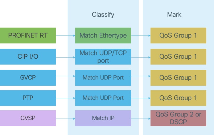 |
The table below summarizes how each traffic type in an industrial machine-vision cell should be classified and marked at the access layer. It aligns the protocol, priority, and recommends DSCP/QoS group so that switches apply consistent forwarding behavior across the entire path. This provides a practical reference for mapping real-time control, GVSP streaming, supervision, and background flows into the appropriate QoS classes.
Table 18. Machine Vision Traffic Types and Recommended QoS Markings
| Traffic Type |
Protocol / Ports / Ethertype |
Criticality |
Suggested Marking |
Notes / Behavior |
| PTP (IEEE 1588 – Event & General) |
UDP 319/320 |
Critical |
DSCP 59 / CoS 7 → QoS-group 1 |
Strict priority timing. Must never be delayed or dropped. Required for deterministic capture and time alignment. |
| CIP Implicit I/O & Safety I/O |
UDP 2222, TCP 44818 |
Critical |
DSCP 55 / CoS 6 → QoS-group 1 |
Real-time control & safety loops. Shares highest priority group with PTP. |
| PROFINET RT |
Ethertype 0x8892 |
Critical |
CoS 6 mapped to QoS-group 1 |
L2-only protocol. Must be mapped into same high-priority group as CIP/PTP. |
| GVCP (Control Plane) Action / Scheduled Action commands |
UDP 3956 |
High |
DSCP 55 → QoS-group 1 |
Low bandwidth but delay-sensitive. Includes Action and Scheduled Action Command messages. |
| GVSP (Vision Streaming) |
UDP >1024 (dynamic) → typically destination: Vision Server |
High / Medium |
DSCP 36 → QoS-group 2 |
High-bandwidth jumbo frames. Requires protection from loss but must not delay control traffic. |
| HMI / Engineering / Supervision |
TCP/UDP (various) |
Medium |
DSCP 26 (AF31) |
Time-sensitive for operator experience but not real-time. |
| Background / Bulk Traffic (Logging, firmware updates, backups) |
TCP 20–21, 80, SFTP, analytics offload |
Low |
DSCP 8 (CS1) / CoS 1 → QoS- group 4 |
Delay-tolerant and droppable during congestion. Recommended for shaping or policing. |
Scheduling and Queueing Behavior
Scheduling determines how packets are forwarded when multiple traffic classes compete for the same egress interface. A correct QoS design must ensure that:
● Real-time control and PTP traffic are always forwarded first, using a strict priority (SP) queue to minimize jitter and delay.
● GVSP image streaming receives a predictable, guaranteed share of bandwidth, ensuring that bursts of large frames do not cause loss.
● Background and best-effort traffic use only the leftover bandwidth after operational flows are satisfied.
● Adequate buffers are reserved for GVSP so that bursty, jumbo-frame image streams are absorbed without affecting I/O or PTP.
● Queue protection and admission control must prevent GVSP or background traffic from filling buffers needed by control traffic.
● No policing is applied to OT control or GVSP traffic, since dropped control packets affect process stability and dropped GVSP packets cause frame loss.
● If rate enforcement is required, it must only be applied to background or non-critical flows.
Platform Behavior: IE3500, IE9300, and Other IE Switches
Cisco Industrial Ethernet platforms implement QoS with eight hardware egress queues per port. Across the IE3x00/IE3400/IE3500/IE9300 families:
● All switches support at least one strict priority queue for IACS and PTP.
● All switches support Weighted Round Robin (WRR) on the remaining queues.
● IE3500 and IE9300 provide two strict priority queues, enabling optimal separation:
Priority Queue 1 (Highest Priority)
● PTP Event
● Real-time control (CIP implicit I/O, PROFINET RT, Safety I/O)
● PTP General
● Vision control-plane (GVCP) if required Purpose: Minimize jitter for timing and control loops.
Priority Queue 2 (High Priority)
● GVSP image streaming
Purpose: Protect image data integrity and absorb bursts without affecting control.
WRR Queues (Remaining Classes)
● OT supervision / HMI / diagnostics
● IT best-effort
● Background and bulk data
● Software updates and backup/archival
Purpose: Provide predictable forwarding for operational traffic while preventing non-critical tasks from affecting I/O or GVSP.
The diagram below shows how traffic classes map strict-priority and WRR queues on IE3500/IE9300 platforms, ensuring separation between control, vision, and background traffic.
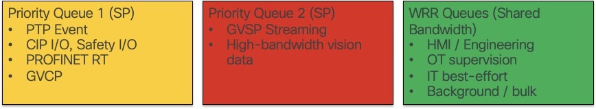 |
The table that follows translates the diagram into exact queue assignments for platforms with one or two strict-priority queues.
Table 19. QoS Traffic Class to Priority Queue Mapping on Cisco IE Switches
| Traffic Class |
Recommended Priority Level |
Mapping on Platforms With 2 Priority Queues (IE3500 / IE9300) |
Mapping on Platforms With 1 Priority Queue (IE3200 / IE3300 / IE3400 / IE3100) |
| Real-Time Control & PTP |
Highest Priority |
Priority Queue 1 |
Priority Queue 1 |
| Vision Streaming (GVSP) |
High Priority (below control) |
Priority Queue 2 |
Highest-Weighted WRR Queue (top WRR class) |
| HMI / Engineering / Supervision |
Medium-High |
WRR Queue 1 |
WRR Queue 1 |
| General OT Management |
Medium |
WRR Queue 2 |
WRR Queue 2 |
| Background / Bulk |
Low |
WRR Queue 3 |
WRR Queue 3 |
| Optional / Site-Specific |
As needed |
WRR Queues 4–7 |
Same mapping as needed |
QoS Validation Results
The proposed QoS design was validated under mixed industrial and vision workloads to confirm correct prioritization and traffic protection. The results are summarized below.
End-to-end QoS behavior was validated using a realistic mixed-traffic profile:
● PROFIsafe controllers running cyclic safety I/O
● Six 1-Gigabit GigE Vision cameras streaming full-bandwidth GVSP simultaneously
● Background traffic intentionally introduced to congest the 10-Gigabit uplinks
Under these conditions, the QoS design behaved as intended:
● No packet loss was observed for PROFIsafe or other industrial control traffic
● No safety faults or communication timeouts occurred
● No GVSP frame corruption or missing blocks were reported by any camera
● All packet loss was confined to the best-effort class, with no impact on operational flows
This confirms that the proposed classification, marking, and scheduling model protects both real-time IACS traffic and high-bandwidth vision workloads even under sustained congestion.
Latency and Jumbo Frame Support
High-resolution machine-vision images typically range from several to tens of megabytes. When transported over a standard 1500-byte MTU, each image must be segmented into thousands of packets. This behavior has direct performance implications:
● Each packet consumes switch buffer entries.
●
● Each packet is individually scheduled and may be dropped during microbursts.
● Each packet generates an interrupt and processing overhead on the receiving NIC/CPU.
● Per-packet Ethernet/IP/UDP headers accumulate into measurable overhead per image.
Increasing the MTU significantly reduces the number of packets required to transmit a single image. A jumbo frame MTU (~9000 bytes) typically reduces packet count by a factor of 5–6×, improving efficiency across the entire path.
The diagram below shows how a single large image segment fits into one Jumbo Frame, versus how the same amount of data must be broken into multiple Standard MTU (1500-byte) packets.
Each of those smaller packets carries its own Ethernet/IP/UDP headers and must be:
● queued
● buffered
● scheduled
● processed individually by every switch and every NIC in the path
This pattern is applied thousands of times per image and dozens of images per second.
The difference in packet count—and the cumulative per-packet overhead—has a measurable impact on latency, jitter and microburst susceptibility along the entire flow.
 |
Integrated Results Over 3× IE3500 Hops
Testing was conducted with a 19.4 MB image transmitted end-to-end across three Cisco IE3500 switches. Results in the table that follows clearly demonstrate the impact of MTU selection.
Table 20. Effect of MTU Size on GigE Vision Image Transfer
| Traffic Class |
Recommended Priority Level |
Mapping on Platforms With 2 Priority Queues (IE3500 / IE9300) |
| Packets per image |
2,286 |
14,023 |
| Total payload |
~19.54 MB |
~20.06 MB (header overhead) |
| Theoretical transmit time @ 1 Gb/s |
~165.3 ms |
~177 ms |
| Measured (Wireshark) |
166.5 ms (matches theory) |
183.6 ms (+6.6 ms vs. theory) |
| Overhead impact |
Minimal (few headers) |
Higher (many headers) |
| Result |
Baseline |
~6–7% slower than jumbo |
Note: VLAN + TrustSec tags contributed ~0.4 ms overhead for jumbo frames and ~2.2 ms for standard MTU.
Why Jumbo Frames Matter in Vision Systems
Using jumbo frames provides three concrete benefits for machine vision workloads:
● Lower protocol overhead: Fewer Ethernet/IP/UDP headers per image → lower total bytes on wire.
● Reduced host CPU load: Fewer interrupts and context switches, improving inference pipeline timing.
● Lower probability of microburst drops: Larger MTU reduces packet concurrency and conserves buffer space on access and aggregation switches.
These benefits scale directly with image size and burst frequency—both of which are high in modern GigE Vision deployments.
Design Guidance
To optimize performance in machine-vision cells:
● Target an MTU of ~9000 bytes and apply it consistently end-to-end:
◦ GigE Vision camera port
◦ All intermediate IE switches (IE3x00 / IE3400 / IE3500 / IE9300)
◦ NICs on IPCs, edge GPUs, or servers
Validate MTU propagation by issuing an ICMP test using a payload close to the configured MTU. Enabling the Don’t Fragment flag ensures that all hops must support the full MTU.
Avoid mixed-MTU paths in the network infrastructure. A single non-jumbo hop forces fragmentation or drops, eliminating all benefits.
Pair jumbo MTU with QoS and queue provisioning, especially when inference workloads coexist with control traffic.
Machine vision introduces traffic behaviors that differ significantly from traditional industrial I/O. High-bandwidth GVSP image streams coexist with extremely timing-sensitive GVCP control packets and PTP synchronization. A resilience strategy must therefore ensure minimal disruption to both control and streaming traffic during link or node failures.
Even momentary outages may cause:
● Missed GVCP heartbeats, causing cameras to drop the control session (typically within 1–5 seconds)
● Incomplete or corrupted GVSP frames
● Trigger misalignment across cameras
● Gaps in quality inspection or robot guidance
● Loss of precise timestamps and traceability
A well-designed resiliency model ensures fast recovery and stable transport during faults—without introducing behaviors that degrade or interrupt vision flows.
GigE Vision includes two independent traffic channels—GVCP and GVSP—with very different reactions to packet loss. The resiliency strategy must protect both.
GVCP (Control, Triggering, Heartbeats)
GVCP carries discovery, configuration, and trigger commands, along with periodic heartbeats that confirm the camera–application session is alive.
Loss of these packets leads to:
● Missed triggers
● Misaligned exposures
● Cameras entering error states
● Session teardown after multiple missed heartbeats (typically 1–5 seconds depending on vendor)
Even brief micro-loops or topology changes may interrupt GVCP sufficiently to disrupt triggering logic or cause cameras to drop out of acquisition state.
GVSP (Image Streaming and Retransmissions)
GVSP carries high-bandwidth image data. GigE Vision 2.0 introduces retransmissions, but:
● Most cameras attempt some resend attempts (such as 30 in a frame) before marking a frame corrupted or discarding it
● Retransmissions add bandwidth load, increasing congestion
● Frame grabbers may pause processing until missing blocks arrive, causing “congestion in the grabber,” delayed pipelines, and additional dropped frames.
● Heavy retransmission bursts can collapse the stream entirely.
Retransmission provides limited protection; it cannot compensate for reconvergence events that introduce loss or bursts of congestion.
Implications for Resiliency Design
Different resiliency protocols offer different recovery characteristics, and their suitability depends on the industrial application running on top of them. While some OT workloads (for example, PROFINET RT, CIP I/O, or general supervision) can tolerate tens or even hundreds of milliseconds of recovery, other workloads such as motion control, synchronized drives, or Safety I/O may require significantly tighter bounds.
The table below shows supported resiliency mechanisms on Cisco Industrial switches. For more information on the protocols and design practices refer to the Networking and Security in Industrial Automation Environments Design and Implementation Guide.
Table 21. Resiliency Mechanisms on Cisco Industrial Switches and Machine Vision
| Mechanism / Protocol |
Claim to Fame |
Recovery From Loss |
Machine Vision Considerations |
| PRP (1G SKUs only) |
Zero-loss dual-attached redundancy |
0 ms |
Best for zero-loss systems But Limited to 1G, and Jumbo frame limited to 2000 bytes. |
| HSR (1G SKUs only) |
Zero-loss ring with replicated frames |
0 ms |
Replicates all traffic; unsuitable for GVSP-heavy rings. Limited to 1G links and jumbo frame is limited to 2000 bytes |
| DLR (1G SKUs only) |
Extremely fast convergence |
~3 ms |
Works for small rings only. Cannot uplink >1G, not suited for large vision workloads. Jumbo frame is limited to 2000 bytes. |
| MRP |
Standards-based, broad multi-vendor support |
~30 ms |
|
| REP Fast (selected IE SKUs) |
Faster variant of REP |
~50 ms |
|
| REP |
Simple Cisco ring |
~250 ms |
Flexible topology options. It allows for resiliency on 10G rings. |
| RSTP / MSTP |
Legacy spanning tree |
~1 s |
|
| Redundant Star with Port-Channel |
Predictable behavior, high-bandwidth uplinks, minimal fault domain |
LACP-based failure 100– 300 ms |
Easy to deploy and maintain. Port-Channel is not a resiliency protocol itself; it stabilizes uplinks, avoids STP events, and supports 10G bandwidth for multi-camera GVSP. |
All the mechanisms in the previous table reconverge well before typical GVCP heartbeat timeouts (1–5 seconds)—so the control session between the camera and inference application generally survives a link or node failure.
As a result, the main considerations for machine vision resiliency become:
● Application tolerance: How many milliseconds of disruption are acceptable?
● High-bandwidth GVSP streaming demands, is 10G required?
● Line speed: High-speed systems (robot guidance, 3D) cannot tolerate any packet loss without impact to quality or operations.
Different architectures provide different trade-offs. Although this CVD did not focus extensively on resiliency beyond addressing camera session teardown caused by hello packet loss, the following section outlines three resiliency options suitable for vision system design, based on insights from previous industrial automation CVD.
Design Considerations: Redundant-Star, 10G Rings, and Lossless Mechanisms
Redundant-Star with Port-Channel
Redundant-Star uses dual uplinks from access switches into a distribution layer, often combined with Port-Channel grouping. While Port-Channel is not a resiliency protocol on its own, this topology provides properties that are valuable in machine-vision scenarios:
● Aggregated bandwidth
● Stable behavior during faults without triggering Layer-2 topology changes
● No unknown-unicast flooding during link transitions
● Fault domains remain small, limited to the affected access switch
This approach is easy to configure and troubleshoot but requires more cabling.
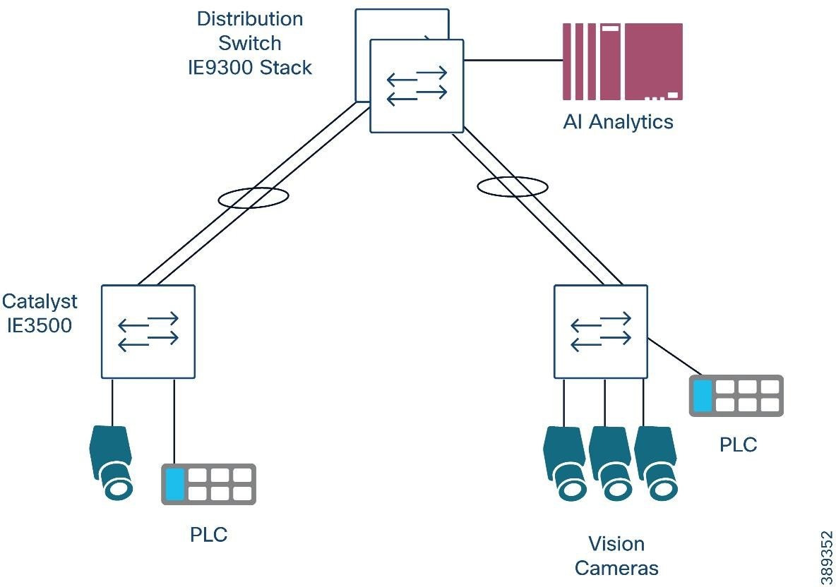 |
10G Rings
In environments where a 10G linear topology is preferred—such as an assembly line with distributed cameras and compute nodes connected in series—Cisco IE switches such as the IE3500, which includes 3×10G ports, enable ring-based designs at 10G speeds.
These architectures allow:
● Compute nodes to sit directly on a 10G path
● End-to-end 10G connectivity along the ring
● Use of ring protocols MRP, REP and REP-Fast and RSTP/MSTP
However, these protocols may introduce brief traffic peaks during topology updates. In high-bandwidth GVSP applications, even short increases in load can cause oversubscription, leading to dropped blocks or retransmissions.
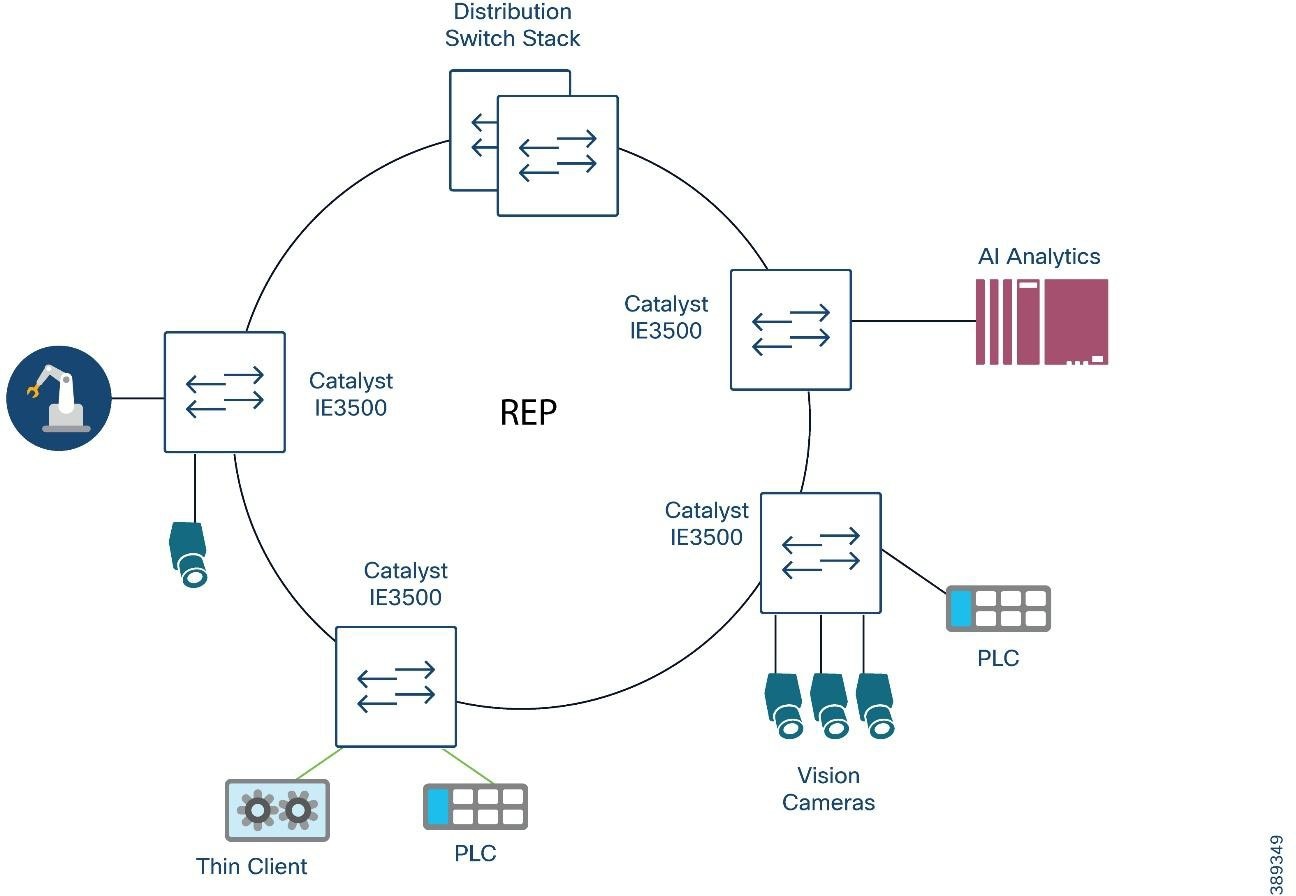 |
Lossless Redundancy Mechanisms
Lossless redundancy mechanisms offer zero-loss behavior during faults, providing continuous packet delivery with no reconvergence time. This makes them attractive for ultra-sensitive machine-vision workloads—robot guidance, pick-and-place, stereoscopic/3D capture, and precision inspection—where even a single dropped frame may cause errors or force a system stop.
Both PRP and HSR achieve this by delivering two copies of every frame so that the receiver always has a valid packet, even during a link or node failure. However, PRP uses 2 independent networks for transmission making it more suitable for modern multi-camera GigE Vision high bandwidth workloads.
Both protocols are limited to 1G interfaces on current Cisco IE platforms. As a result, they remain practical only for small or moderate-bandwidth machine vision cells, or where lossless operation is required, and bandwidth demands remain below 1G.
Additionally, jumbo frames are limited to 2000 bytes when using PRP/HSR. This eliminates the usual benefits of 9K MTUs—higher protocol efficiency, lower interrupt rate on the host, and reduced per-packet overhead. As a result, camera traffic generates more packets per frame, which increases burstiness and can stress 1G links faster.
DHCP Server Port-Based Address Allocation for Vision Systems
Most industrial cameras support DHCP for initial configuration, making onboarding significantly faster during commissioning and device replacement. However, OT environments typically require fixed and predictable IP addressing to maintain stable integrations with PLCs, SCADA, MES, vision analytics services, and historian systems. Cisco IOS DHCP Server Port-Based Address Allocation provides the best of both models: devices can obtain IP addresses dynamically, yet the assigned address is tied to the physical switch port rather than the camera’s MAC address or DHCP client identifier. This ensures that when a camera is replaced—whether for maintenance or failure—the new device immediately receives the same IP address simply by connecting it to the same port. This behavior preserves downstream configuration, avoids engineering rework, and maintains continuity in tightly coupled vision inspection flows. This feature is supported only on Cisco IOS DHCP servers and can be combined with reserved-only pools to enforce strict control of IP allocations in industrial networks.
Design Guidance
● Use DHCP for rapid onboarding, especially in camera-dense cells where manual IP assignment slows commissioning and complicates replacements.
● Enable Port-Based Address Allocation on the DHCP server to maintain stable IP addressing for OT systems that depend on fixed device identities (PLCs, SCADA tags, MES connectors, historian mappings).
● Map each camera to a dedicated switch port and reserve an address in the appropriate DHCP pool. This preserves deterministic addressing without sacrificing the operational convenience of DHCP.
● Avoid relying on MAC-based DHCP reservations in factory environments. Devices replaced under maintenance often ship with different MAC addresses, breaking reservation logic and requiring engineering updates.
● Use reserved-only pools when strict IP governance is required. This ensures that only expected devices receive addresses and prevents accidental reassignment during swaps or cabling mistakes.
● Apply this method primarily at the access layer
Machine Vision Security considerations
Digital transformation in manufacturing is reshaping the Cell/Area Zone, bringing in modern networking, COTS hardware, machine-vision cameras, IPCs, and GPU servers. These systems increase performance and insight but also broaden the attack surface, especially as IT/OT convergence accelerates. Addressing security in this zone requires more than technology—IT and OT teams must share operational context, understand process constraints, and apply consistent security practices without impacting availability or real-time workloads.
Security in the Cell/Area Zone should be viewed as part of an end-to-end plant architecture. Controls must align with safety requirements, 24/7 uptime expectations, and the high OEE demands of modern production. This section introduces the foundational security capabilities for the Cell/Area Zone—network hardening, segmentation, visibility, and secure remote access—before evolving toward scalable architectures built around Cisco Cyber Vision, TrustSec, and Secure Equipment Access (SEA), as detailed in the Cisco Industrial Security Design Guide 3.1.
Machine vision adds new types of devices—cameras, GPU servers, IPCs—that often run general-purpose operating systems. This expands the attack surface inside the Cell/Area Zone. The objective is to protect the process without compromising availability.
Machine-vision security focuses on the following core goals:
● Limit access to cameras, IPCs, and GPU servers using strong access control (802.1X/MAB), identity-based policies, and per-device authorization.
● Prevent lateral movement between production lines or adjacent vision cells through VLAN isolation, TrustSec micro segmentation, and flow-specific policies.
● Gain deep visibility into device behavior and traffic patterns via Cisco Cyber Vision, including device identity, protocol use, and deviations.
● Provide secure, auditable remote access for system integrators and vision vendors, using SEA integrated into Cyber Vision.
Together, these objectives create a foundation where every device has a known identity, every flow is authorized, and every change is visible.
These objectives align with the broader guidance in the Cisco Industrial Security Design Guide 3.1.
● Apply port security and MAC limits on camera and IPC access ports.
● Disable unused switchports and unnecessary management services.
● Enforce camera and IPC manufacturer security baselines.
● Maintain strict OS and firmware governance for GPU servers and vision IPCs.
Access Control, Authentication, and Authorization (ISE)
Machine-vision endpoints typically lack traditional user authentication, and many operate with limited OS-level hardening. Therefore, identity enforcement must occur at the network edge. Cisco ISE provides:
● 802.1X for capable devices (IPCs, servers)
● MAB profiling for cameras and appliances without supplicants
● Dynamic SGT assignment based on 802.1X/MAB and profiling, classifying Cameras, Vision Servers, IPCs, Vendors, and Management hosts.
● Authorization policies that control network access (permit/deny) and assign the appropriate SGT so that downstream enforcement (TrustSec, ACLs) can restrict communication to required industrial flows.
This ensures devices cannot access workloads or networks beyond the minimal set required for vision operation.
Visibility With Cisco Cyber Vision
Cyber Vision provides critical visibility into machine-vision environments by identifying:
● Camera types, firmware, and communication behavior
● IPCs, GPU servers, and OS-level activity
● Camera/server flows
● Anomalous service exposure or unexpected communication paths
Reference: Cisco Industrial Security DG 3.1 (Cisco Cyber Vision Architecture & Sensors)
Sensor Scale & Placement for Vision Traffic
Machine-vision networks generate high-bandwidth, bursty, asymmetric streams. Proper sensor design is essential. Following are aspects to consider:
● Avoid oversubscription: Multi-Gbps GVSP streams can overwhelm a sensor.
Use selective SPAN or focus on control-plane traffic when full streams are unnecessary.
● Jumbo-Frame Considerations:
The IE3500 and IE9300 do not support jumbo frames on the AppGigabit interface used for Cyber Vision sensors. Jumbo frames are not supported on other platforms.
◦ Jumbo GVSP video frames may not be forwarded to the sensor.
◦ Control-plane packets (GVCP, discovery traffic) are small and remain visible, ensuring endpoint discovery, flow identification, and anomaly detection.
This allows Cyber Vision to provide meaningful visibility even when the sensor cannot capture full-size data frames.
Secure Remote Access (SEA) for Vision Support
Secure remote access is a critical requirement for system integrators deploying and tuning vision systems, as well as for camera and software vendors providing remote support.
In current releases, SEA is included as part of the Cyber Vision application, providing a unified platform that combines:
● Endpoint visibility
● Vulnerability context
● Secure, auditable remote access
This greatly simplifies support workflows:
● Integrators and third-party vendors can access cameras and IPCs through SEA without exposing the broader OT network.
● Each session is recorded, authenticated, and tied to a specific approval workflow.
● Access is time-bound and role-specific, reducing the risk of uncontrolled remote connections.
Refer to the Secure Equipment Access (SEA) section in the Cisco Industrial Security Design Guide 3.1 for architecture, advantages, and operational recommendations.
Network Segmentation for Machine Vision
Dedicated Vision VLANs
Cameras, IPCs, inference servers, and management endpoints SHOULD reside in separate VLANs. This avoids inter-line exposure, reduces broadcast domain and simplifies traffic enforcement.
Micro segmentation
Vision workflows are directional. Enforce rules such as:
● Only vision servers/IPCs may initiate GVCP/GVSP toward cameras.
● Cameras must not initiate traffic toward enterprise or Internet destinations.
● The management VLAN is reachable only from approved sources.
This is reinforced with TrustSec SGT-based policies (see below).
TrustSec for Vision Micro segmentation
The Industrial Security 3.1 DG provides general TrustSec design guidance. This document highlights some key elements of the validated architecture.
● The IE3500, recommended for many vision-cell architectures, supports full TrustSec, including SGT enforcement and inline SGT propagation.
This allows micro segmentation at the access layer, closest to the cameras.
● CTS inline SGT propagation is not compatible with PTP.
If PTP is required (for example, for synchronized imaging), remove inline propagation and instead use:
◦ Control-plane propagation via SXP, or
◦ Static IP-to-SGT bindings, applied at the access or distribution layer.
This ensures segmentation without impacting deterministic timing.
Policy Examples (Conceptual)
● SGT:Camera → SGT:Vision-Server: Permit
● SGT:Camera → SGT:MES: Deny.
Putting It Together: Vision Security Architecture
A secure machine-vision architecture combines:
● Hardening at access ports
● VLAN isolation for cameras, IPCs, and management
● TrustSec SGT policies aligned with camera-to-server flow patterns
● PTP-aware SGT propagation choices
● Cyber Vision visibility, including SEA-based remote access
● Sensor placement decisions based on stream bandwidth and jumbo-frame support
Together, these controls protect the vision system while preserving the real-time requirements of high-speed inspection environments.
Security posture must not break production:
● Changes to ACLs, SGT policies, or firewall rules should be tested in shadow/monitor mode where possible
● When deny by default policies are used a backup static configuration should be added to the switch configurations that guarantees uptime if connection to policy server is down.
The following configuration tools are used in this guide for configuration and management of Cisco IE switches.
You can use Device Manager, which is in the switch memory, to manage individual and standalone switches. This web interface offers quick configuration and monitoring. You can access Device Manager from anywhere in your network through a web browser. For more information, see the Device Manager online help.
Some of the features that can be configured with Device Manage are:
● Port Settings including Jumbo frame support
● Etherchannels
● REP
● Smartports
● STP
● VLAN
● VTP
● AAA
● Multicast
● QoS
In medium and large-scale industrial deployments, Cisco Catalyst Center provides centralized automation, configuration consistency, and lifecycle management across hundreds of Cell/Area Zone switches. Machine-vision architectures benefit significantly from Catalyst Center templates, policy integration, and streamlined operational workflows.
Standardization Through Templates
Catalyst Center enables repeatable, error-free provisioning of vision cells by pushing standardized configuration templates for:
● VLANs for camera networks, IPCs, and vision servers.
● QoS policies, including ingress classification (dSCP/CoS), GVSP prioritization, and egress scheduling.
● PTP settings, including profiles, boundary/transparent clock roles, and interface-level PTP configuration.
● Security baseline settings, such as AAA, TACACS+/ISE integration, syslog, SNMP, SSH hardening, and password policies.
Templates ensure that every new vision cell is deployed with consistent behavior and no configuration drift.
Integrated Policy Management with Cisco ISE
Catalyst Center integrates directly with Cisco ISE to automate identity and policy deployment across industrial switches. Through this integration, Catalyst Center:
● Registers and synchronizes switches with ISE, ensuring each device is onboarded as a trusted network access device (NAD).
● Configures AAA, including RADIUS/TACACS+
● Pushes TrustSec settings such as enabling CTS on the switch
● Configures SGTs and segmentation policies
This integration allows ISE to make the authentication and authorization decisions, while Catalyst Center ensures the correct device-level configurations are pushed reliably and consistently across the entire Cell/Area Zone switching layer.
Plug-and-Play (PnP) Onboarding for Vision Cells
For new production lines or RMA scenarios, Catalyst Center’s Plug-and-Play automates:
● Zero-touch onboarding of industrial switches.
● Automatic provisioning of templates, VLANs, PTP roles, and security settings upon connection.
● Replacement (RMA) workflows where configuration and firmware are restored automatically when a new switch is inserted.
Lifecycle Management and Upgrades
Catalyst Center simplifies operational tasks that are otherwise disruptive in manufacturing:
● OS upgrades and firmware alignment across dozens or hundreds of switches.
● Pre- and post-checks, golden images, and scheduled maintenance windows to reduce risk.
● Configuration drift detection to identify unauthorized changes that could impact vision workloads or segmentation.
This ensures the switching layer supporting vision systems remains stable, standardized, and compliant.
Campus Automation Capabilities (Layer 2 Automation)
Recent Catalyst Center releases, particularly from version 2.3.7 onwards, introduce Campus Automation, which exposes Layer 2 (L2) network automation capabilities directly through the user interface (UI). This feature is especially valuable for industrial environments that require simple yet controlled configuration changes at the network edge.
Campus Automation enables:
● Port-level device onboarding by assigning VLANs or Security Group Tags (SGTs) directly through the UI, simplifying device provisioning without requiring CLI expertise.
● Brownfield network management by discovering existing switches, learning their configurations, and enabling incremental configuration changes at scale.
For more details, see the Cisco Catalyst Center for Industrial Automation Solution Brief.
The switch CLI is based on Cisco IOS software and is enhanced to support desktop-switching features. You can fully configure and monitor the switch. You can access the CLI either by connecting your management station directly to the switch management port, or a console port, or by using Telnet or SSH from a remote management station.
For system integrators and OEMs, SD-Flash–based zero-touch provisioning is a powerful tool:
● Configuration files, IOS images, and other artifacts are pre-loaded on an SD card.
● The SD card is shipped with the switch or installed on site.
● On boot, the switch reads and applies the configuration, enabling consistent, rapid deployment of identical vision cells.
This is especially useful when building a repeatable cell design that will be cloned across multiple lines, plants, or customers.
ip access-list extended CIP
10 permit tcp any any eq 44818
20 permit udp any any eq 2222
ip access-list extended GVCP_CTRL
permit udp any any eq 3956
permit udp any eq 3956 any
mac access-list extended Profinet_macacl
permit any any 0x8892 0x0
ip access-list extended GVSP_VISION
permit udp any range 49152 65535 host 10.131.2.20
ip access-list extended PTP_EVENT
permit udp any any eq 319
ip access-list extended PTP_GENERAL
permit udp any any eq 320
class-map match-all 1588-PTP-Event
match access-group name PTP_EVENT
class-map match-all 1588-PTP-General
match access-group name PTP_GENERAL
class-map match-any GVCP_SMALL
match access-group name GVCP_CTRL
class-map match-any CIP
match access-group name CIP
class-map match-any class_match_profinet_in
match access-group name Profinet_macacl
class-map match-any GVSP
match access-group name GVSP_VISION
class-map match-any DSCP_EF
match dscp ef
class-map match-any COS6
match cos 6
class-map match-any QOS_GROUP_1
match qos-group 1
class-map match-any GVSP_DSCP
match dscp 36
policy-map INGRESS_POLICY
class 1588-PTP-Event
set qos-group 1
class 1588-PTP-General
set qos-group 1
class CIP
set qos-group 1
class class_match_profinet_in
set qos-group 1
class GVSP
set dscp 36
class GVCP_SMALL
set qos-group 1
policy-map QOS_OUT
class QOS_GROUP_1
priority level 1
class GVSP_DSCP
priority level 2
class class-default
This design and implementation guide is an evolution of a significant set of industrial solutions issued by Cisco. In many ways, this document amalgamates many of the concepts, technologies, and requirements that are shared in industrial solutions. The vertical relevance will be maintained, but shared technical aspects are essentially collected and referred to by this document.
● The existing documentation for manufacturing and oil and gas can be found on the Cisco Design Zone for Industry Solutions page.
● The Cisco Catalyst 9300 is positioned as the distribution switch where there is a controlled IT environment.
◦ Cisco Catalyst 9000 switching product page:
● Cisco Catalyst 9300 StackWise—480 configuration:
● Industrial Ethernet switching product page:
● IEC Standards — IEC 61588 Precision clock synchronization protocol for networked measurement and control systems
● GigE Vision – global camera interface standard developed using the Gigabit Ethernet communication protocol
Table 22. Previous Industry Documentation
| Industry |
Solution |
Description |
| Manufacturing |
|
Solution to assist manufacturers seeking to integrate or upgrade their Industrial Automation and Control System (IACS) networks to standard Ethernet and IP networking technologies. |
|
|
Enable rapid and repeatable machine connectivity, providing business improvements such as overall equipment effectiveness (OEE) and machine monitoring. |
|
| Connected Factory—Network Management for Operational Technology
|
Discusses the use of Cisco's Industrial Network Director application for monitoring industrial network assets and discovering automation devices within the context of the Connected Factory solution. |
|
| Oil & Gas |
Validated Designs for Oil and Gas
|
Cybersecurity for Oil & Gas Connecting Remote and Mobile Assets |