Connected Transportation System
Available Languages
Table of Contents
About Cisco Validated Design (CVD)
A Growing Demand for Connected Transportation
Overcoming the Challenges of a Mobile Network
Extreme Environmental Conditions
Limited Wireless Network Coverage (3G/4G, WiFi)
Movement of Rail Cars among Trains
Benefits of a Connected Rail System
End-to-End Connected Rail System
The Cisco Connected Rail System
The Cisco Unified MPLS Transport
About Cisco Validated Design (CVD)
The CVD program consists of systems and solutions designed, tested, and documented to facilitate faster, more reliable, and more predictable customer deployments. For more information visit http://www.cisco.com/go/designzone .
ALL DESIGNS, SPECIFICATIONS, STATEMENTS, INFORMATION, AND RECOMMENDATIONS (COLLECTIVELY, “DESIGNS”) IN THIS MANUAL ARE PRESENTED “AS IS,” WITH ALL FAULTS. CISCO AND ITS SUPPLIERS DISCLAIM ALL WARRANTIES, INCLUDING, WITHOUT LIMITATION, THE WARRANTY OF MERCHANTABILITY, FITNESS FOR A PARTICULAR PURPOSE AND NONINFRINGEMENT OR ARISING FROM A COURSE OF DEALING, USAGE, OR TRADE PRACTICE. IN NO EVENT SHALL CISCO OR ITS SUPPLIERS BE LIABLE FOR ANY INDIRECT, SPECIAL, CONSEQUENTIAL, OR INCIDENTAL DAMAGES, INCLUDING, WITHOUT LIMITATION, LOST PROFITS OR LOSS OR DAMAGE TO DATA ARISING OUT OF THE USE OR INABILITY TO USE THE DESIGNS, EVEN IF CISCO OR ITS SUPPLIERS HAVE BEEN ADVISED OF THE POSSIBILITY OF SUCH DAMAGES.
THE DESIGNS ARE SUBJECT TO CHANGE WITHOUT NOTICE. USERS ARE SOLELY RESPONSIBLE FOR THEIR APPLICATION OF THE DESIGNS. THE DESIGNS DO NOT CONSTITUTE THE TECHNICAL OR OTHER PROFESSIONAL ADVICE OF CISCO, ITS SUPPLIERS OR PARTNERS. USERS SHOULD CONSULT THEIR OWN TECHNICAL ADVISORS BEFORE IMPLEMENTING THE DESIGNS. RESULTS MAY VARY DEPENDING ON FACTORS NOT TESTED BY CISCO.
The Cisco implementation of TCP header compression is an adaptation of a program developed by the University of California, Berkeley (UCB) as part of UCB’s public domain version of the UNIX operating system. All rights reserved. Copyright © 1981, Regents of the University of California.
Cisco and the Cisco logo are trademarks or registered trademarks of Cisco and/or its affiliates in the U.S. and other countries. To view a list of Cisco trademarks, go to this URL: www.cisco.com/go/trademarks . Third-party trademarks mentioned are the property of their respective owners. The use of the word partner does not imply a partnership relationship between Cisco and any other company. (1110R)
- Any Internet Protocol (IP) addresses and phone numbers used in this document are not intended to be actual addresses and phone numbers. Any examples, command display output, network topology diagrams, and other figures included in the document are shown for illustrative purposes only. Any use of actual IP addresses or phone numbers in illustrative content is unintentional and coincidental.
CRS 1.5 System Overview
With the proliferation of mobile devices, businesses have a critical and immediate mandate to stay current in terms of how voice, video, and data are provided, accessed, and consumed. High-speed wireless access is perceived by consumers, mobile workers, and now even non-mobile workers perceive as the "new normal. As a result, this trend opens the door to new business and revenue opportunities, increased safety and security, and on-demand entertainment.
The Cisco Connected Rail System (CRS) defines a multi-year ongoing development program by Cisco's Systems Development Unit (SDU) that builds towards a flexible, programmable, and cost-optimized network infrastructure, targeted to deliver in-demand wireless network services to transportation vertical markets. As the market leader in providing network equipment and systems in both fixed and mobile networks, Cisco is uniquely positioned to help operators transition network operations, technologies, and services to meet these new demands for mobile access. Cisco is delivering proven architectures, with detailed design and implementation guides, as proof points of our strategy to service the network needs of the transportation sector.
Release 1.5 of Cisco's CRS focuses on providing rail operators and service providers (SPs) an end-to-end system infrastructure design capable of delivering high-speed voice, video, and data services to passengers, rail operators, and other functions. CRS 1.5 addresses the following main system areas:
- Connected Train—Onboard high-speed wired and wireless infrastructure.
- Offboard Infrastructure—High-speed wireless connectivity between the train and track.
- Connected Trackside—Trackside network provides access to high-speed transport.
- Safety and Security—Video surveillance and incidence collaboration.
The system is a continuation of CRS Release 1.0, which provided the necessary infrastructure for rail operators to implement a federally mandated Positive Train Control (PTC) system. CRS 1.5 leverages the Unified MPLS Transport architecture developed in the Fixed Mobile Convergence (FMC) Cisco Validated Design (CVD) to accommodate the backhaul needs of CRS deployments of virtually any size or scale.
A Growing Demand for Connected Transportation
To truly understand the impact of mobile access, consider a few facts found in Cisco's Visual Networking Index (VNI):
- Global mobile data traffic continues to grow at a rapid rate. Global mobile data traffic grew 70 percent in 2012, reaching 885 petabytes per month. 2013 continued that trend with an 81 percent year-over-year growth rate.
- Mobile video traffic exceeded 50 percent for the first time in 2012. Mobile video traffic was 51 percent of traffic by the end of 2012.
- Average smartphone usage grew 81 percent in 2012. The average amount of traffic per smartphone in 2012 was 342 MB per month, up from 189 MB per month in 2011.
- In 2012, the number of mobile-connected tablets increased 2.5-fold to 36 million, and each tablet generated 2.4 times more traffic than the average smartphone. In 2012, mobile data traffic per tablet was 820 MB per month, compared to 342 MB per month per smartphone.
Mobile data traffic will reach the following milestones within the next five years.
- Annual mobile data traffic will continue to grow exponentially. By 2018, global mobile data traffic will reach 15.9 exabytes per month, or a run rate of 190 exabytes annually.
- Smartphones will continue to be the primary access medium for mobile data traffic. Smartphones will be 66 percent of total mobile data traffic in 2018, compared to 62 percent in 2013.
- Mobile data network connection speeds will continue to increase. Globally, the average mobile network connection speed increased 2.6-fold in 2013 (1.4 Mbps) and will nearly double by 2018, reaching 2.5 Mbps.
- Mobile data traffic offload will grow. 52 percent of global mobile data traffic will be offloaded in 2018, up from 45 percent in 2013.
- Video will continue to drive mobile data usage. By 2018, 69 percent of the world's mobile data traffic will be video, up from 53 percent in 2013.
CRS 1.5 will help SPs and rail operators overcome the challenges of designing and implementing a transportation-oriented high-speed wireless infrastructure to meet the needs of current and future applications.
Overcoming the Challenges of a Mobile Network
Providing a reliable, high-speed, always-on wireless access service on a train poses many challenges. This section discusses some of those challenges and how the CRS addresses them.
Extreme Environmental Conditions
When deploying a high-speed network on a train, allowing wireless access to the trackside, some equipment will need to be installed on the train and/or outdoors. Therefore, the equipment must be able to endure the following conditions:
- Wide ambient temperature ranges
- Extreme weather conditions including rain, snow, sleet, winds, sun, dust, etc.
- Vandalism
- Vibration
The CRS uses hardened form-factor devices to overcome these challenges. These devices include Cisco Industrial Ethernet switches, hardened servers, access points, and video surveillance cameras.
Limited Power Supply
Trains do not have the access to power an office building or even a parking lot does. Therefore, the design calls for limiting the number of devices that require a power outlet nearby. Installing Industrial Ethernet switches that provide power-over-Ethernet (PoE) contributes in a major way to the ease of deployment by allowing the switch to power an IP camera or wireless access point directly over the network cable.
Limited Space
Train cars are designed to carry passengers or cargo; they are not for large network deployments. Therefore, the equipment used must consume a small amount of space. Cisco's Industrial Ethernet switch is a small form-factor, DIN rail-mountable switch. The Cisco 6050 high definition video surveillance camera is also much smaller than most cameras and can endure harsh environments.
Limited Wireless Network Coverage (3G/4G, WiFi)
While the goal is to provide high-speed wireless coverage of the entire rail infrastructure via trackside WiFi deployments, geographic factors, right-of-way issues, and interference factors may make WiFi coverage unfeasible in some areas. Additionally, even in areas where WiFi coverage has been deployed, there could be short-term interruptions in coverage. In these cases, the network may be designed to use a 3G and/or 4G cellular link as an alternative. Allowing the system to leverage WiFi and cellular connectivity from multiple SPs is also possible.
Movement of Rail Cars among Trains
In some deployment scenarios, rail cars may not move from train to train, while other deployments may necessitate a flexible design that allows a rail car to be pulled for maintenance or inserted into a different train. Some rail operators may want to offboard wireless traffic from every car, while others may only want to offboard from the front and back cars. The CRS allows for the movement of rail cars with minimum configuration changes, or none at all.
Benefits of a Connected Rail System
The following benefits are derived from a connected rail system.
Commuters and Rail Personnel
The CRS offers many benefits to a passenger. Consumers and mobile workers have come to expect ubiquitous mobile Internet access, even on a train. This type of mobility is designed so that mobile workers can make the most effective use of their commute, casual commuters can access the Internet for social networking and entertainment, and rail personnel can access the business-critical tools that they require to provide safe and efficient transportation. New business cases arise with connected rail. Network operators may bundle high-speed mobile network services with ticket plans or offer daily, weekly, or monthly data plans to frequent riders.
Operators
Rail operators can use the onboard high-speed network for other purposes such as onboard Passenger Information Systems (PIS). This may include streaming content to LCD screens installed on the cars that displays location, weather, advertisements, or travel tips. Personal entertainment units may stream movies during long trips. The conductor or train operator may use the network to communicate to passengers or crew over an IP-based intercom system. Online ticketing and purchasing services may also leverage the network.
Safety and Security
The connected rail network can play a critical role in securing the passengers, crew, train and trackside. A high-speed network on the train allows for IP video surveillance that may capture or prevent employee theft, passenger misconduct, and vandalism, and provide valuable information for law enforcement. The Cisco Video Surveillance Manager (VSM) may be configured to provide live and/or recorded video to any permitted PC on or off the train.
An IP network can also serve as the backbone of the Cisco IP Interoperability and Collaboration System (IPICS). This system simplifies radio dispatch operations and improves response to incidents, emergencies, and facility events. Cisco IPICS dissolves communication barriers between land mobile radio systems and devices such as mobile phones, landline phones, IP phones, and PCs, supporting communications among users of all devices, wherever they are located.
End-to-End Connected Rail System
An end-to-end CRS is comprised of four main architectural areas: the onboard, trackside, transport, and data center. Figure 1 shows the high-level architecture of an end-to-end system.
Figure 1 High-Level Architecture of Connected Rail System 1.5
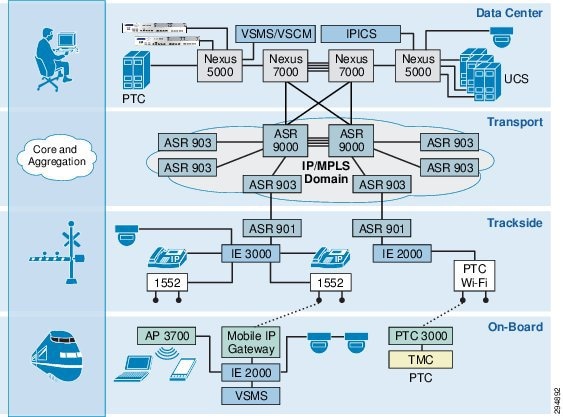
Onboard
A high-speed wired and wireless network onboard the train provides a resilient infrastructure to deliver numerous services. Hardened form-factor switches and routers provide the necessary infrastructure for consumer and business mobility. Wireless access points provide WiFi connectivity to rail personnel and commuters for entertainment, passenger information, Internet access, and more. Comprehensive video surveillance is supported, with a dedicated video surveillance media server on each car to store video archives from the onboard IP cameras.
Transport of services to and from the onboard train infrastructure is accomplished via a design that supports multiple wireless technologies, including WiFi, cellular, and others. Mobile IP routers support the routing of traffic over these wireless connections, enabling seamless handover between available connections. WiFi connectivity is achieved through WiFi workgroup bridges connected to the Mobile IP routers to provide high throughput wireless connectivity to trackside access points. Cellular connectivity is via integrated 4G/LTE modems in the Mobile IP Gateway. A train will have two or more Mobile IP gateways for redundancy among the off-boarding infrastructure.
Trackside
Outdoor access points are installed along the trackside infrastructure to provide WiFi connectivity to the train as it progresses along the tracks. The trackside APs are ruggedized and ready for virtually any environment. They can be connected to the transport network through either a fiber or copper connection and can even provide PoE to a nearby device, such as a video surveillance camera. The wireless APs can be connected to Cisco Industrial Ethernet switches, which will then connect directly to the access nodes of the transport network.
Transport
The Cisco Fixed Mobile Convergence (FMC) CVD is leveraged to accommodate the transport needs of CRS deployments between the trackside access network and the data center. Communication between the data center and onboard devices relies on a redundant and resilient bi-directional communications network spanning from the data center to the trackside. The transport network, consisting of the access, aggregation, and core networks, provides a resilient communications path between the field devices and the data center. This will include ruggedized Ethernet switching at the edge, and a multipath unified MPLS transport network with sub-second re-convergence.
Data Center
The data center houses several of the application servers used within CTS. The Back Office Server (BOS) and mobility anchor used for Positive Train Control, the VSM application servers including the Operations Manager and Long Term Storage, and any other servers, such as an IPICS server, may be found in the data center. These application servers may run directly on physical servers or be virtualized through the use of a hypervisor.
The network infrastructure used within the data center may be comprised of the Cisco Nexus line of data center switches. The Virtualized Multiservice Data Center (VMDC) CVD is leveraged in CRS 1.5 to provide a high-speed, reliable data center network.
The Cisco Connected Rail System
The CRS, as shown in Figure 2, offers an end-to-end system designed to enable the deployment of high-speed mobile networking for rail applications. Passengers and rail personnel can connect their wireless devices to onboard WiFi access points to obtain access to the corporate, retail or commercial networks, as well as the Internet. A high-speed wired and wireless onboard network can also be used for other business objectives, including safety and security. CRS 1.5 combines Cisco's expertise in wireless mobility, video surveillance, IP collaboration, transport network, and data center networking into a complete solution for rail applications.
Figure 2 CTS Network Design with Cellular Backup
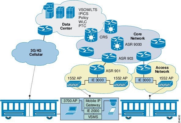
A train may have wireless off-boarding on as little as two cars or as many as on every car. Each off boarding point will prefer a WiFi connection to the trackside network. However, they can also be deployed with a cellular backup option for areas where WiFi access is not available trackside.
Wireless Access Points
Cisco 3700 Series wireless LAN access points, as shown in Figure 3, are used onboard the train for commuters, rail personnel, and machines to attach to and gain access to enterprise networks and/or the Internet. Supporting 802.11ac, it offers the speed and bandwidth required by high-density networks and high performance applications.
Figure 3 Cisco Aironet 3700 Series Access Points
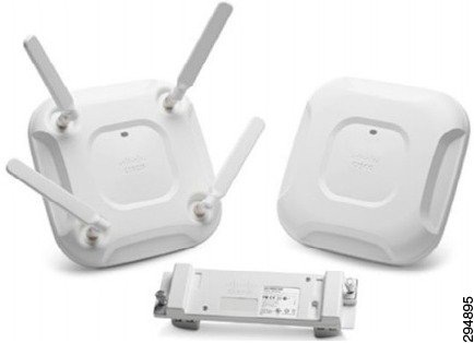
The Cisco 3600 Series wireless LAN access points will be used onboard the train to offboard the mobile traffic to the trackside WiFi access points. A future release of CRS will support the 3700 Series AP for this role.
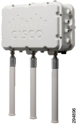
Trackside WiFi access points use the Cisco 1552 AP, as shown in Figure 4, designed for external use offering 802.11n connectivity over 2.4 or 5 GHz. The 1552 utilizes a heavy-duty IP67-rated enclosure designed to withstand extreme environments. Some models, which allow the device to be powered directly over the network cable (PoE), offer an output PoE port that can be used to power a nearby device, such as a surveillance camera
Figure 4 The Cisco 1552 Series Outdoor Wireless Access Point
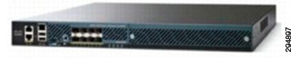
Wireless LAN Controller
The Cisco 5500 Series Wireless Controller, as seen in Figure 5, is used for its high-performance, scalable, and reliable services for wireless networking. It can support up to 500 access points and allows for sub-second stateful failover of all access points to the standby controller in the event of a failure. For larger deployments, the Cisco 8500 Series Wireless Controller offers the same functionality with higher scale. The controllers support Cisco CleanAir® technology for dealing with surrounding RF interference and Cisco Application Visibility and Control (AVC) for Deep Packet Inspection (DPI) and integration with Cisco Prime infrastructure.
Figure 5 Cisco 5500 Series Wireless Controllers
Subscriber Policy Control
The Cisco Service Provider WiFi solution provides a platform for SPs to handle the growing services offered to mobile devices. Subscriber policy control in CRS 1.5 is leveraged from the Cisco Service Provider WiFi solution, which is a platform for business and service innovation. It is capable of utilizing mobile device type, context, and location to create revenue-generating opportunities from the growing services offered to mobile devices. Cisco Quantum Policy Suite (QPS) is an integral part of policy control in this model.
The Cisco QPS for WiFi is a carrier-grade policy and subscriber data management software solution that enables SPs to control, monetize, and personalize WiFi offerings on their networks. The solution offers a platform for delivering a variety of new services that take advantage of intelligent WiFi network attributes. QPS supports the following use cases to deploy value-added WiFi services:
- Subscriber Authentication and Authorization
- Differentiated Services (DiffServ)
- Quota and Usage Control
- 3GPP Mobile Data Offload
The system can also integrate with the Cisco Intelligent Services Gateway (ISG), which consists of several features built into the Cisco line of IOS routers. This is commonly used to authenticate and authorize subscribers using RADIUS or DHCP, as well as controlling and accounting for per-subscriber and per-services use for post-paid and pre-paid billing.
Industrial Ethernet
The Cisco Industrial Ethernet line of switches will be used on and off the train. Onboard the train, a rail-certified L2 switch, as shown in Figure 6, is used that will provide two gigabit Ethernet ports, four PoE ports, and twelve more 10/100 Ethernet ports. All of these ports have M12 Ethernet connectors used to withstand the vibrations of a moving train. This switch is also designed to handle wide ambient temperature ranges and has a ruggedized enclosure.
Figure 6 Cisco Industrial Ethernet Switches
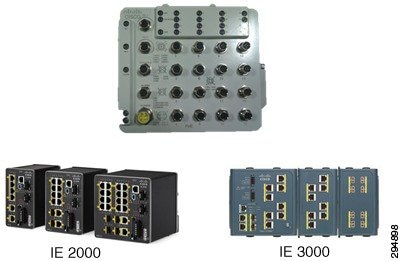
Offboard the train, in outdoor enclosures, standard Industrial Ethernet switches will be used. These switches also support a wide ambient temperature range, but use standard RJ-45 network jacks. Multiple mounting options are available, including DIN rail mounting or rack mounting. Layer 2/3 connectivity on the switches allows for flexible configuration options attaching to the access network.
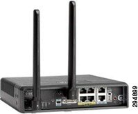
Mobile IP Router
The Cisco 819 Integrated Services Router (ISR) offers a flexible off boarding mechanism and L3 routing. Onboard devices use the 819, as shown in Figure 7, as their default gateway and the 819 serves as a Mobile Access Gateway (MAG) using Proxy Mobile IP version 6 (PMIPv6), providing dynamic multipoint management of connectivity via WiFi infrastructure and cellular infrastructure to enable always-on IP mobility to those devices. In the data center, a Cisco ASR 1000 will serve as the Local Mobility Anchor (LMA) to terminate the PMIPv6 tunnel and propagate routing information. Multiple 819 devices can be used and load balance their links off the train through the use of Performanc Routing.
Figure 7 Cisco Integrated Services Router 819
IP Video Surveillance
IP video surveillance plays a major role in the safety and security of rail operators and their passengers. Video Surveillance Manager (VSM) is the management suite used to view and archive video, and manage the video surveillance infrastructure. The system has three major components:
- Video Surveillance Operations Manager (VSOM)
- Video Surveillance Media Server (VSMS)
- Video Surveillance Cameras
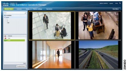
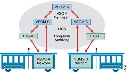
Video Surveillance Operations Manager (VSOM) is the user interface for both operators and users of the video surveillance system. Each VSOM server will have one or more VSMS associated with it, and each VSMS will have one or more IP cameras or encoders streaming video to it. VSOM, as shown in Figure 8, allows administrators to create user accounts with role-based permissions allowing users to view only video that they are permitted to view. Cameras and servers can be associated with Locations and Sub-Locations that represent a logical structure of the real-world environment. For very large deployments, an optional Video Surveillance Federator (VSF) can be deployed to aggregate the video from cameras associated with multiple VSOM servers.
Figure 8 VSOM Provides a User Interface to View and Configure Video
Video Surveillance Media Server (VSMS) is the server to which associated cameras stream their video. The video is stored on the media server, and from there, streamed to VSM clients to be viewed by rail personnel. The VSMS can also be configured as a Long-Term Storage (LTS) server whereby video can be stored for long period of time (months or years). In CRS, each car will have its own dedicated VSMS to store video from within the car for the day. Each night, the VSMS will upload the video archives to a LTS server. Onboard VSMS should be deployed in a ruggedized form factor with M12 connectors to handle the vibrations of a moving train.
Cisco's line of IP video surveillance cameras includes indoor and outdoor cameras that support pan-tilt-zoom (PTZ), auto-focus, and many more features. Powered by PoE and with support for Cisco Medianet, they are easy to deploy. The cameras support both standard and high-definition video and multiple streams. Rail-certified cameras are available with M12 connectors for use onboard the train. For offboard video surveillance systems, analog video encoders can be used in addition to IP cameras. This allows the customers to utilize existing analog cameras instead of replacing all cameras at once. Analog encoders take an analog video input from analog cameras over a coaxial cable and convert it to an IP video stream before transmitting it to a VSMS.
Figure 9 The Logical Layout of a Video Surveillance Management System
The Cisco Unified MPLS Transport
Another critical consideration is to provide scalable and resilient backhaul of mobile voice, video and data traffic between the train and the data center. While some railroads may already have a backhaul transport network to some degree, the CRS system incorporates a Unified MPLS Transport network design for Greenfield network deployments and as an upgrade path to enhance the capacity and resiliency of existing backhaul networks.
The FMC CVD is leveraged to accommodate the backhaul needs of CRS deployments of virtually any size or scale. While the design breaks down the network into access, pre-aggregation, aggregation, and core segments, some segments can be combined depending on the size and scope of the network.
The network design example in Figure 10 represents a smaller network where the core, aggregation, and pre-aggregation networks are combined into a single network domain. The access network is where the trackside wireless access points would access the network via Ethernet..
Figure 10 FMC Spans the Access, Aggregation, and Core Network from Trackside to Data Center
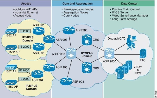
The example in Figure 10 assumes a flat Label Distribution Protocol (LDP) Label Switched Path (LSP) across the core and aggregation networks. Together, these two networks form one IGP and LDP domain. The MPLS mobile access network is based on MPLS access rings with ASR 901 access routers, and integrated with labeled BGP LSPs. This network can scale up to thousands of access routers and hundreds of pre-aggregation network nodes.
In cases where a larger backhaul transport is needed, the core and aggregation networks can be separated into independent IGP/LDP domains. Inter-domain MPLS connectivity would continue to be based on hierarchical-labeled BGP LSPs. A network design such as this would allow for tens of thousands of access nodes and thousands of pre-aggregation nodes.
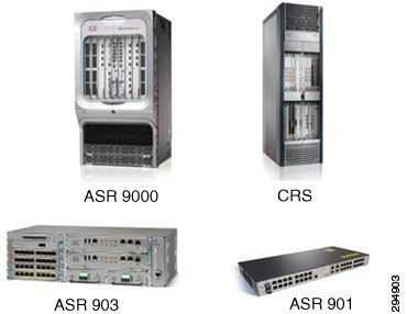
Several unified MPLS architecture models have been tested, validated, and documented as part of the FMC CVD. Further, because many FMC production deployments have been conducted, railroads have access to a mature and tested design.. Table 1 and Figure 11 show the components validated as part of the FMC design.
Figure 11 Platforms Used In the Unified MPLS Transport Network
Summary
The Cisco Connected Rail System (CRS) provides a full end-to-end system design to deliver the required infrastructure and applications for high-speed wireless mobility for users and devices onboard a train. This onboard high-speed network can be used by commuters to access the rail operator's consumer and retail networks, while allowing rail personnel to access the enterprise network. This also enables future train deployments such as passenger information systems, ticketing, entertainment, and safety and security applications. WiFi policy control allows the rail operator to control subscribers' access, usage, and quality-of-service to monetize the service an offer 3GPP wireless data offload to cellular SPs.
CRS 1.5 also offers an end-to-end video surveillance system to increase the safety and security of the rail operator and its passengers. This system is designed to scale to virtually any number of cameras, and to allow the movement of train cars between trains with minimal or no configuration necessary. Video can be viewed from onboard or offboard the train with a web browser, and archived in long-term storage.
 Feedback
Contact Cisco
- Open a Support Case

- (Requires a Cisco Service Contract)
This Document Applies to These Products
- Collaboration Endpoints - Retired Products
- Conferencing - Retired Products
- Contact Center - Retired Products
- Optical Networking - Retired Products
- Routers - Retired Products
- Security - Retired Products
- Servers - Unified Computing (UCS) Retired Products
- Storage Networking Retired Products
- Switches - Retired Products
- Video - Retired Products
- Wireless - Retired Products