Cisco Unified Branch Medium Branch Deployment Guide
Available Languages
Bias-Free Language
The documentation set for this product strives to use bias-free language. For the purposes of this documentation set, bias-free is defined as language that does not imply discrimination based on age, disability, gender, racial identity, ethnic identity, sexual orientation, socioeconomic status, and intersectionality. Exceptions may be present in the documentation due to language that is hardcoded in the user interfaces of the product software, language used based on RFP documentation, or language that is used by a referenced third-party product. Learn more about how Cisco is using Inclusive Language.
- US/Canada 800-553-2447
- Worldwide Support Phone Numbers
- All Tools
 Feedback
 Feedback
Branch offices commonly face IT challenges such as limited onsite technical resources, increased operational complexity from managing multiple disparate devices, and heightened security vulnerabilities due to fragmented solutions. These challenges are compounded by the need to scale quickly to support new technologies like AI and IoT, all while ensuring a consistent and reliable user experience across locations.
Cisco Unified Branch helps address these issues by providing an integrated, full-stack solution that consolidates essential networking and security functions—including routing, next-generation firewall, switching, and Wi-Fi—into a centrally managed solution. With Cisco Validated Designs (CVDs) and built-in automation toolkits like Cisco Workflows and Branch as Code (BaC), organizations can streamline deployment and management, reduce the risk of misconfiguration, and enforce consistent security policies. This unified approach not only simplifies branch operations but also enhances scalability, strengthens security, and delivers a seamless customer experience.
Cisco Validated Designs (CVDs) are thoroughly tested blueprints with prescriptive guidance for deploying Cisco solutions across various technologies. Cisco Unified Branch combines this validated design expertise with modern automation through Cisco Workflows and Branch as Code (BaC), allowing enterprises and partners to deploy, manage, and scale branch networks consistently and reliably, in line with modern DevOps approaches.
About this guide
The Cisco Unified Branch architecture, with supported platforms and a variety of use cases, is being developed, tested, and released in phases. This current phase supports multiple flavors of MXs, Cisco secure routers, Cisco switches, and access points at the branch using the Meraki cloud dashboard for management, and Auto VPN for the SD-WAN overlay. Catalyst switches must run in cloud mode (not device mode), meaning they must be managed and configured only from the Meraki dashboard. Small, medium, and large branch designs have been defined.
The Cisco Validated Design (CVD) documentation for Cisco Unified Branch consists of a design guide and several deployment guides. The design guide provides an overview of the Unified Branch architecture for small, medium, and large branches, discussing the hardware, services, and features supported. It also includes the configuration choices for each branch design. The deployment guides cover an example small branch, medium branch, and large branch deployment, along with step-by-step instructions on how to deploy each of them using the Meraki dashboard.
This guide covers an example Unified Branch medium branch deployment, which consists of two WAN transports, two routers deployed as a High Availability (HA) pair, two switches in a physical stack, and one access point. The deployment includes firewall policy, performance-based routing, 802.1x and Mac Authentication Bypass (MAB), QoS, Wireless guest and corporate traffic, various security and management features, Cisco Secure Access secure Internet access (SIA), Adaptive Policy, an external RADIUS server for VLAN and SGT assignment, and Thousand Eyes, Splunk, and XDR integrations.
This guide does not cover Branch as Code (BaC) or Cisco Workflows, as they are covered separately, however, the design and configuration closely reflect what is implemented by BaC and Workflows. Refer to Appendix D for additional documentation references.
Deployment example
This topology depicts a branch (Branch 2/Site 2) composed of:
● 2 MX routers in an HA pair (MX85s)
● 1 switch stack consisting of 2 MS layer-2 LAN switches (MS150-24P-4Gs)
● 1 access point (CW9172)
There are two WAN interfaces on each MX, each connected to an Internet transport. Branch 2 is configured in a hub and spoke topology, with Data Center 1 as the primary hub and Data Center 2 as the secondary. Cisco Secure Access is leveraged to provide secure Internet access (SIA) for most traffic at the branch. At the data center, multiple shared services exist, including DNS, DHCP, RADIUS, and various management platforms for SNMP, syslog, and NetFlow. For SNMP, traps from the dashboard and polling to the dashboard and devices are implemented. An external RADIUS server is leveraged for assignment of VLANs and SGT tags.
This diagram depicts a logical view of the topology:
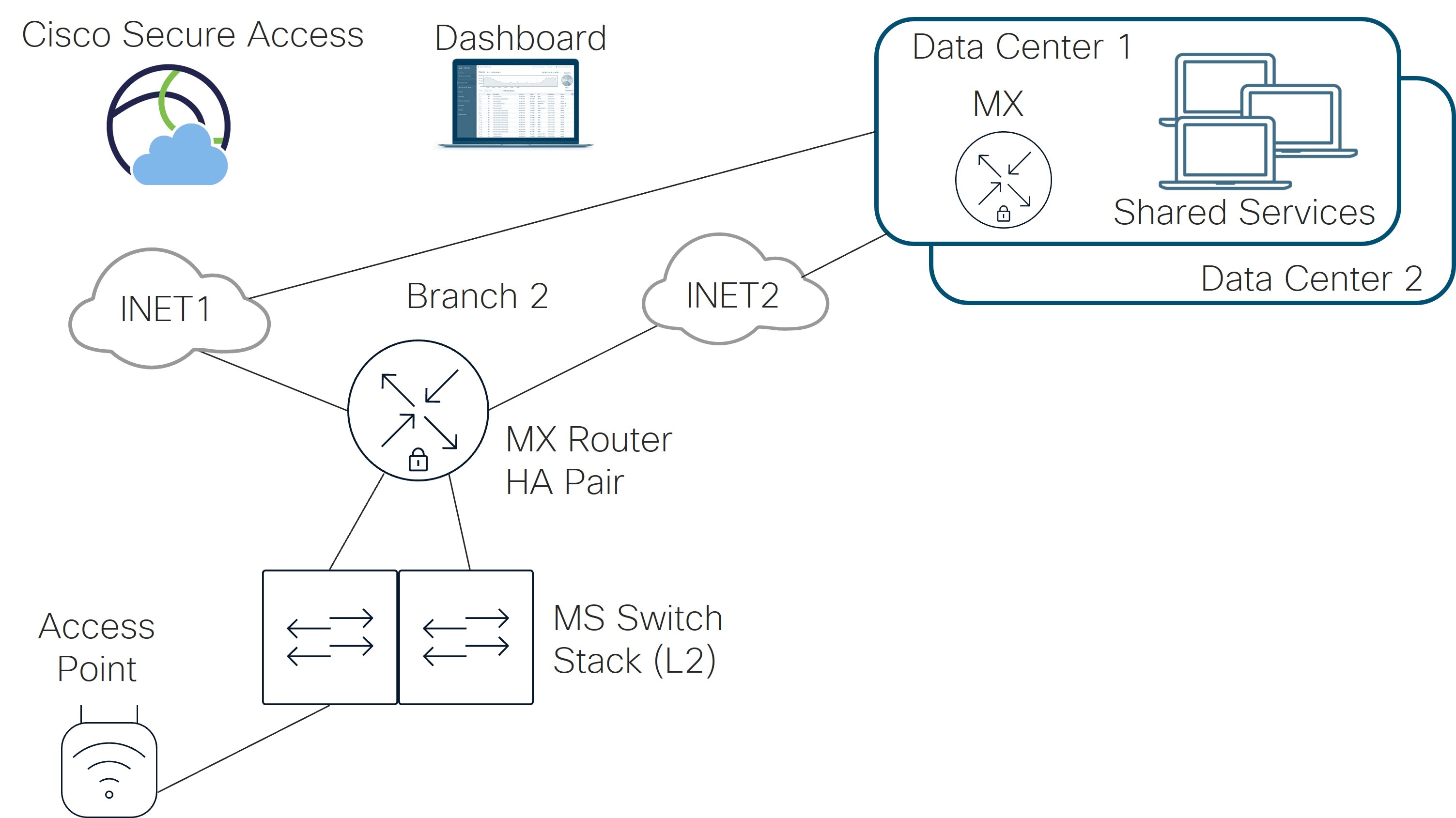
Refer to Appendix A to view the hardware models and code versions used in this example topology. New dashboard GUI versions were used wherever possible at the time of this writing (February/March 2026). Also, Appendix B reflects the dashboard and device settings that were used so the step-by-step and screenshots can be skipped.
Physical topology
In this example, the MX routers operate in active/passive mode and share access to each Internet transport. Only one MX router is active at any one time. The L2 switch stack is repurposed to front-end both Internet transports so only one connection to each transport is needed for the pair of routers. A separate VLAN (901) is provisioned for one transport, and a separate VLAN (902) is provisioned for the other transport. These VLANs are not carried on the trunks on the LAN-side.
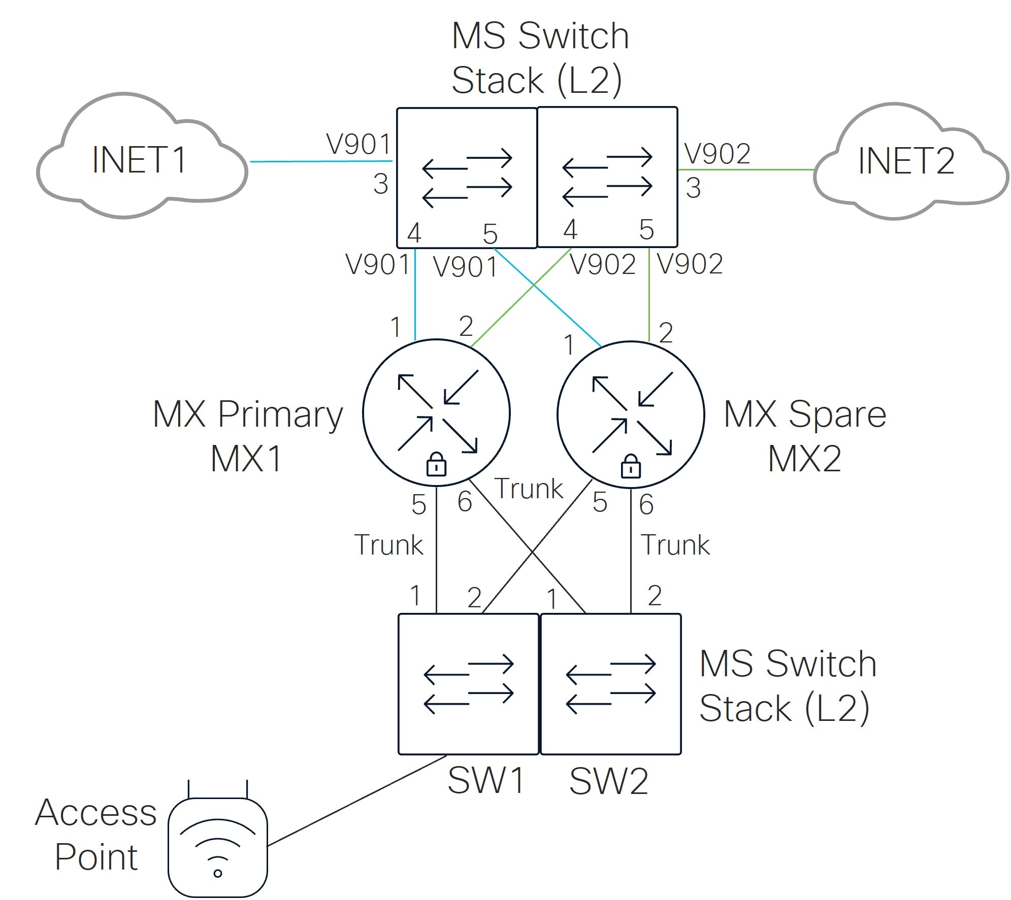
The table lists the ports used in this example:
| Device |
Port # |
Device |
Port # |
Device |
Port # |
Device |
Port # |
Port configuration |
| SW1 |
3 |
INET1 |
N/A |
SW2 |
3 |
INET2 |
N/A |
Access Port (VLAN 901 or 902) |
| SW1 |
4 |
MX1 |
1 or 3 |
SW2 |
4 |
MX1 |
2 or 4 |
Access Port (VLAN 901 or 902) |
| SW1 |
5 |
MX2 |
1 or 3 |
SW2 |
5 |
MX2 |
2 or 4 |
Access Port (VLAN 901 or 902) |
| SW1 |
1 |
MX1 |
5 |
SW2 |
1 |
MX1 |
6 |
Trunk Port (VLANs 1 (NATIVE),10,20,30,40,50,999) |
| SW1 |
2 |
MX2 |
5 |
SW2 |
2 |
MX2 |
6 |
Trunk Port (VLANs 1(NATIVE),10,20,30,40,50,999) |
| SW1 |
9 |
Access Point |
0 |
|
|
|
|
Trunk Port (VLANs 1,10,20,30,40,50,999(NATIVE)) |
On the switches, these additional ports in this table are reserved for infrastructure, AP connections, and devices:
| Device |
Port # |
Device |
Port configuration |
| MX1 |
7-14 |
Unused |
Disabled |
| SW1 or SW2 |
6-8 |
Any Infrastructure |
Disabled |
| SW1 or SW2 |
10-12 |
Dedicated to APs |
Disabled |
| SW1 or SW2 |
13-24 or 13-48 |
Dedicated to Devices |
Disabled |
Tech tip: On the MX router, If the backup WAN interface will be enabled at some point, plan using the SFP ports, physical ports 1 and 2 from the beginning (instead of ports 3 and 4). When the backup WAN port is enabled, it will use physical port 4 and move the Internet ports to physical port 1 and 2 (SFP ports). Enabling the backup WAN interface will cut off Dashboard control traffic to the devices if ports 3 and 4 are actively being used for Internet access. If you add SFP modules to a running system, the MX will need a reboot in order to detect and start utilizing port 1 (or 3). Alternatively, the active port can be specified by configuring the port through the local status page.
Network description
These details further describe the network:
● The MX routers for the hubs and branch are deployed in routed mode.
● There is an active MX router and a passive MX router. Each MX connects to a switch which gives each MX access to the same Internet transport through a shared VLAN. In this example, the MX routers leverage a virtual uplink IP address that is shared when sending traffic to the Internet. This virtual uplink IP address must be in the same subnet as the IP addresses of the MXs and also must be different from both MX uplink IP addresses.
● This table describes the seven interface VLANs that are defined on the MX router. The subnet structure is designed so global firewall rules can be minimized. SITE# refers to Branch/Site “2” in this example. DHCP can be local to the branch or relayed to the data center to a centralized DHCP server. The DNS server can be located on the Internet or at the data center. Some VLANs are not advertised across the auto VPN overlay (indicated by Disabled under the VPN Mode column).
| VLANs |
Subnet structure |
DHCP location |
DNS location |
VPN mode |
| VLAN 1 (Default) |
192.168.128.0/24 |
Local |
Internet (Use OpenDNS) |
Disabled |
| VLAN 10 (DATA) |
10.<VLAN#>.<SITE#>.0/24 |
Data Center |
Data Center |
Enabled |
| VLAN 20 (VOICE) |
10.<VLAN#>.<SITE#>.0/24 |
Data Center |
Data Center |
Enabled |
| VLAN 30 (IOT) |
10.<VLAN#>.<SITE#>.0/24 |
Data Center |
Data Center |
Enabled |
| VLAN 40 (PCI) |
10.<VLAN#>.<SITE#>.0/24 |
Data Center |
Data Center |
Enabled |
| VLAN 50 (GUEST) |
172.16.99.0/24 |
Local |
Internet (Use OpenDNS) |
Disabled |
| VLAN 999 (INFRA) |
10.250.<SITE#>.0/24 |
Local |
Data Center |
Enabled |
● VLAN 1 is used for initial onboarding to the dashboard, then all device management is switched to tagged VLAN 999 with unique addressing so this traffic can use the various services in the data center, such as syslog, NetFlow, and SNMP services. One exception is the Access Point. The switch trunk to each access point is configured for native VLAN 999 so the AP management traffic has reachability in VLAN 999.
● In general, traffic from one VLAN cannot access another VLAN due to firewall rules. Exceptions are made for shared services (DATA subnet can access printer services within the branch and DATA, IOT, VOICE, PCI, and INFRA subnets can access shared services within the data center). Guest and Default VLAN traffic and some traffic from the DATA and INFRA VLANs are permitted to go out Direct Internet Access (DIA).
● The WAN uplinks on the MX router are set to rate limit on the provider sub-line rate, and VPN tunnels are formed on both WAN transports. No load-balancing is done for direct Internet traffic. Internet break-out traffic, or direct Internet traffic, is confined to Guest and Default VLAN traffic, a few corporate SaaS applications, and dashboard traffic for the INFRA VLAN for downstream devices (switch and AP dashboard traffic). All other traffic that is Internet-bound goes through Cisco Secure Access tunnels at the site.
● Active/standby tunnels are set up from the active MX router to Cisco Secure Access. One pair of active/standby tunnels are sourced from one WAN transport (INET1) and another pair of active/standby tunnels are sourced from the second WAN transport (INET2). The tunnels leverage health checks. Traffic to the active tunnels is load balanced by default.
● Performance-based routing is enabled for corporate SaaS traffic using the Internet break-out, and VoIP and video conferencing, a custom critical application, and default traffic using the Auto VPN overlay.
● All switch trunk port connections in this example carry just the VLANs defined on the MX router, including the native VLAN 1. The native VLAN is defined as 999 on trunk ports to any AP.
● Each MX router has one trunk connection to each switch of the 2-switch stack, and all other ports on the MX are unused (ports 7-14). The unused ports on the MX are disabled. Each switch has ports designated for Infrastructure that are unused (ports 6-8) in this example and are shutdown. The AP port in this example is configured as a trunk, and all unused AP trunk ports are disabled. The left-over ports on each switch are configured as access ports and are configured for BPDU guard and 802.1x/MAB. All ports are enabled for rapid spanning-tree and storm control.
● Adaptive Policy is enabled. Four groups are defined as part of DATA VLAN 10 (Finance_User_Group, Marketing_User_Group, Finance_Server_Group, and Marketing_Server_Group). It is assumed that the servers reside in the data centers, while the users reside in the branch. A policy is defined that dictates the permissions between groups. Configurations are set to ensure that SGT tags are trusted/propagated across the Auto VPN and between the MX/switch and switch/AP.
● 802.1x enabled on the access ports of each switch leverage an external server configured for RADIUS authentication and accounting. Multi-Auth mode is used. The policy type is hybrid authentication, meaning, if there is no authentication for 802.1x, Mac Authentication Bypass (MAB) can be used instead. Voice authentication is also enabled. There is no access to the network if either 802.1x or MAB authentication fails. If authentication succeeds, a VLAN is passed back from the RADIUS server, putting the user into the DATA, VOICE, IOT, or PCI VLANs. An SGT tag is also passed back from the RADIUS server. In this example, ISE (version 3.4) is used as the external RADIUS server. Refer to Appendix C for ISE settings used in this example.
● For QoS on each switch, the GUEST VLAN traffic DSCP is not trusted and set to DSCP 0. For other VLAN traffic, DSCP is trusted. On the MX router, default traffic rules are used, and rules are added to include guest traffic and custom critical application traffic.
● Wireless guest traffic is configured for Open authentication (no encryption), mandatory DHCP, and a click-through splash page which must be acknowledged before being allowed on the network. DHCP is performed by the MX router and traffic is tagged for the GUEST VLAN (VLAN 50). Layer 2 LAN isolation is enabled so guest users cannot communicate with each other, and a per-client bandwidth and per-SSID bandwidth limit is enabled. SSID availability is scheduled according to a custom schedule. The Guest Wi-Fi uses 2.4 and 5 GHz bands and AI-RRM is enabled.
● Corporate Wi-Fi traffic is configured to use 802.1x Enterprise authentication with RADIUS (authentication and accounting). WPA3 transition mode is used, and fast roaming and protected management frames are enabled (protected management frames allow unsupported clients). DHCP is performed by the MX router and by default, traffic is tagged for the DATA VLAN, although the Override VLAN tag is enabled. RADIUS will respond back with a group policy name (DATA, VOICE, IOT, or PCI) which has a VLAN set based on the identity of the user. Separately, an SGT tag is passed back. SSID availability is scheduled according to a custom schedule. The Corp Wi-Fi uses 2.4, 5, and 6 GHz bands, band steering, and AI-RRM is enabled.
● Wi-Fi 7 is not enabled yet for the Corporate Wi-Fi as it requires a separate access point from the guest Wi-Fi due to security requirements. Per-group SSID configuration is available starting in MR release 32.1.4, where Wi-Fi 7-compliant SSIDs can co-exist on the same AP as non-Wi-Fi 7-compliant SSIDs as long as they are in separate SSID groups. The feature is still in Beta status as of 32.1.5, hence why it is not included yet in the Unified Branch design. Refer to the WPA3_Encryption and Configuration Guide for additional information.
● Splunk, Thousand Eyes, and XDR are deployed in the example network.
For this deployment, these steps are discussed:
Step 1. Complete the prerequisites
Step 2. Create a new network
Step 3. Onboard the devices
Step 4. Upgrade devices (if needed)
Step 5. Configure devices
Step 6. Verify device operation
When the devices are onboarded, configured, and verified, configuration templates can optionally be created then modified from the configured network which can then be used to quickly deploy additional branches. Refer to the Managing Multiple Networks with Configuration Templates for more details.
There are several prerequisites that need to be addressed before configuration and onboarding can begin. This includes ensuring Internet connectivity for the network devices, creating a Meraki dashboard account and Organization within the dashboard, ensuring the network devices are added to the Organization Inventory in the dashboard, ensuring the required licenses are added to the dashboard, and having account access for the feature integrations (Cisco Secure Access, ThousandEyes, Splunk, and XDR). There may also be hardware, software, and licensing requirements for certain features. Refer to the Cisco Unified Branch Design Guide for additional information.
Internet connectivity
All configurations can be performed on the Meraki cloud dashboard. Devices should have connectivity to the Internet to connect to the Meraki cloud. Device onboarding is simplified if the provider provides an IP address, gateway, and DNS information through DHCP to the WAN uplink on the MX router, as device registration to the dashboard is automatic. In addition, it is important to ensure that if there are any firewalls upstream from the router, the proper rules are configured so the device can reach the proper cloud services. Refer to Upstream Firewall Rules for Cloud Connectivity for details on what IP addresses and ports should be allowed.
Meraki dashboard account and organization
Ensure a Meraki dashboard account and organization are created. The organization is created at the same time as the account. From the account, organizations, networks, and devices are managed. An organization is made up of multiple networks, and each network is made up of one or more devices. A network typically correlates to a physical location. Refer to Creating a Dashboard Account and Organization for more information.
Organization device inventory
Ensure the devices to be managed are added in the Organization inventory on the dashboard (Organization > Configure > Inventory).
The inventory page contains all devices in the organization, including those that have been added to networks as well as those that are not currently assigned to a network within the organization. Devices must first be claimed before being able to be used or assigned to a network in the Dashboard.
Devices can be entered using an order claim key or cloud ID. The preferred method is using the order claim key as this ensures that all hardware from an order is claimed. The order claim key can be found in order shipment email notifications or in the corresponding Cisco Commerce Workspace (CCW) order under the Order Claim Key field.
Note: If your order includes software subscription licenses, you can also claim the subscription along with your hardware using the order claim key.
Procedure 1. To claim devices using the order claim key:
Step 1. Go to Organization > Configure > Inventory and select + Claim devices.
Step 2. In the pop-up window, enter the order claim key then click Claim order.
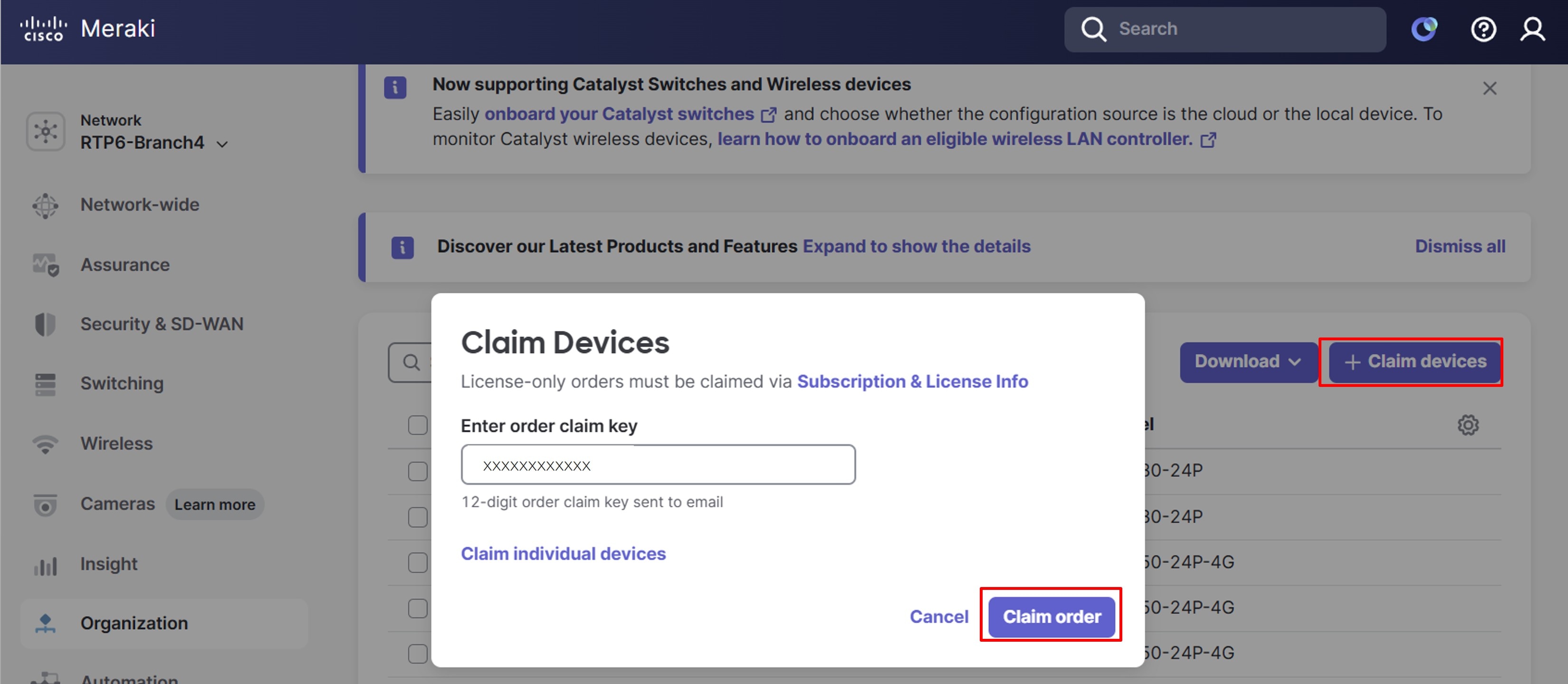
Individual devices can also be claimed. The Cloud ID for a device is a unique identifier used for claiming and managing the device in the Meraki dashboard. For individual Meraki devices, the serial number and cloud ID are the same and can be found in the order shipment email notifications or on the devices themselves.
Procedure 2. To claim individual devices:
Step 1. Go to the Organization > Configure > Inventory > + Claim devices pop-up window.
Step 2. Select Claim individual devices.
Step 3. Enter the Device Cloud ID (Meraki serial number) then click Claim devices.
For individual Catalyst devices, the device serial number and cloud ID are not the same. The Meraki dashboard accepts only the cloud ID for claiming and managing these devices. For -M devices, the Cloud ID can be found in the order shipment email notifications, or you may find a cloud ID label on the device. Also, if you are on the console while it boots, you can view the model number, serial number, cloud ID, and mac address before it becomes Meraki-managed.
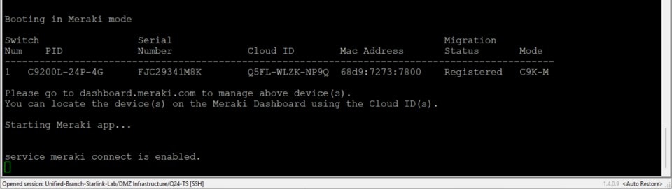
For non -M Catalyst devices, the cloud ID is generated from the CLI after upgrading the switch to the minimum IOS XE image, which is IOS XE 17.15, but some models require IOS XE 17.18. Refer to Conversion from CLI-managed IOS XE Catalyst Switches to Cloud Management with Cloud Configuration.
For additional information on onboarding, refer to the Meraki Hardware and Software Onboarding Guide.
Licenses
Every device requires an active license. A license provides access to the Meraki Dashboard for cloud-based management and monitoring, offers support and firmware updates, and unlocks specific features depending on the product. Subscription licensing is recommended. If a subscription expires, after a grace period, the ability to manage devices is lost for all networks bound to that subscription.
Ensure the required licenses are added to the dashboard. License status can be found on the Organization > Configure > License Info page on the dashboard. Licenses are added automatically if they are part of an order number that was entered in the Inventory page, otherwise, they can be added manually using a Claim Key if the order number is not known or the license is ordered separately from the devices.
For more detailed information, review the Getting Started Checklist.
In addition to device licensing, additional licensing may be required depending on the feature. Refer to the Cisco Unified Branch Design Guide for more information about feature licensing and hardware and software requirements.
Create a new network
Procedure 3. To create a new network:
Step 1. On the dashboard, go to Organization > Configure > Create Network.
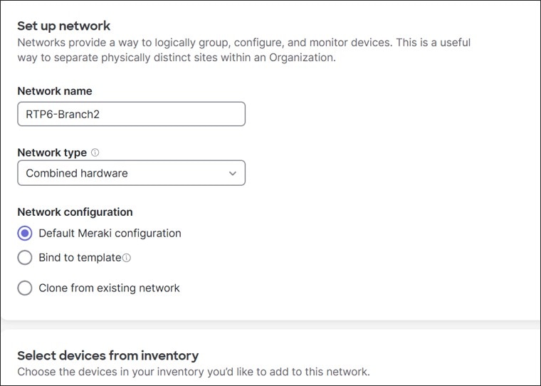
Step 2. In the text box, enter the Network name (RTP6-Branch2) and specify the Network type (if needed, from the drop-down menu (Combined hardware)). Before additional configurations are added, this network uses the Default Meraki configuration.
Step 3. Select the devices from inventory that should be included in the network (these should have been added during the prerequisite steps).
Step 4. Select Create network.
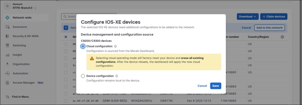
If Catalyst devices are added, a window may appear to indicate the device management and configuration source before adding those devices to the network. Devices can be in cloud mode, where configuration is sourced from the Meraki Dashboard, or in device mode where the configuration is local to the device. In Unified Branch, only cloud mode is supported at this time.
The dashboard switches to the newly created network.
Procedure 4. To set the local status page password for the devices connecting to this network:
Step 1. Under the new network, navigate to Network-wide > Configure > General. The local device status page is enabled by default.
Step 2. Under Device configuration > Local credentials, click Change password.
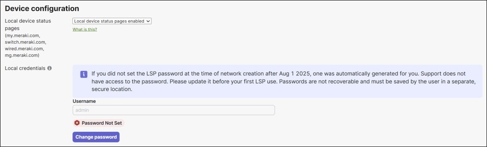
Step 3. Under Password, type a secure password, which must be 14 characters long and must include a number, uppercase letter, lowercase letter, and a symbol.
Step 4. Click Update password.
Step 5. Click Save.
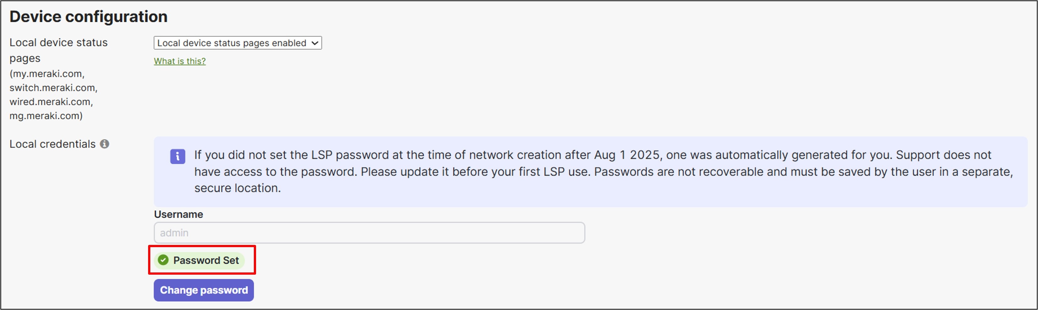
Step 6. You may need to reload the web page to remove the “Password Not Set” notification outlined in red. Remember this password because it won’t be visible in the dashboard when set.
For onboarding, the primary MX router is onboarded first, followed by the switches, APs, and spare MX router. The cabling is then completed. As part of the cabling completion, the switches are moved between the MX routers and Internet transports.
These instructions assume the devices are powered off and not initially cabled:
Onboard the primary MX router
Procedure 5. To onboard the primary MX router:
Step 1. Ensure the MX router can get a DHCP lease and internet connectivity from at least one of the WAN connections so the MX can connect to the dashboard.
Step 2. If IP addressing to the service provider must be manual:
a. Connect locally to the MX.
b. Add an IP address, netmask, gateway, and DNS information to Internet 1 (physical port 1 (SFP) or 3 (RJ45)) or Internet 2 (physical port 2 (SFP) or 4 (RJ45)).
Refer to Cisco Meraki Local Status Page: Overview and Cisco Meraki Local Status Page: Security and SD-WAN for additional information. This example assumes DHCP is available from both internet service providers.
Step 3. Power the primary MX router on and connect WAN interface 1 (SFP port 1 in this example) to its WAN transport.
When it reaches the dashboard, a firmware upgrade may take place to update the device to the latest stable release. When the LED on the router turns solid white, the MX is connected to the dashboard, and its default configuration should be downloaded.
Onboard the switches
Procedure 6. To onboard the switches:
Step 1. After the MX router is fully on board and while the switches are still powered off, cable the switches together using their stacking cables.
◦ Stack port 1 switch 1 à stack port 2 switch 2
◦ Stack port 2 switch 1 à stack port 1 switch 2
Refer to Switch Stacks if needed for additional information.
Step 2. Connect the uplink of switch 1 (port 1) to the proper port on the primary MX router (port 5).
Step 3. Connect the uplink of switch 2 (port 1) to the proper port on the primary MX router (port 6).
Step 4. Power on the switch stack.
Wait for both switches to be completely onboarded. When the switch management traffic reaches the dashboard, a firmware upgrade may take place to update the devices to the latest stable release. When the LED on the switch is solid white, the switch is connected to the dashboard, and its default configuration should be downloaded.
Onboard the Access Point (AP)
Procedure 7. To onboard the AP:
● After both switches in the switch stack are fully onboard, connect the uplink of the AP to the proper port on the switch (switch 1 port 9 in this example).
Through PoE, the AP is powered on. After AP management traffic reaches the dashboard, a firmware upgrade may take place to update the device to the latest stable release. When the LED on the AP is solid white, the AP is connected to the dashboard, and its default configuration should be downloaded.
Modify switch configurations
Stack configuration
Procedure 8. To configure a stack:
Step 1. Ensure that the switches are recognized as part of a stack on the dashboard.
Step 2. Under the newly created branch (RTP6-Branch2), go to Switching > Monitor > Switch Stacks.
If the stack was auto-provisioned by the dashboard, it shows up as a Stack Name with the listed Stack Members in mac addresses form.
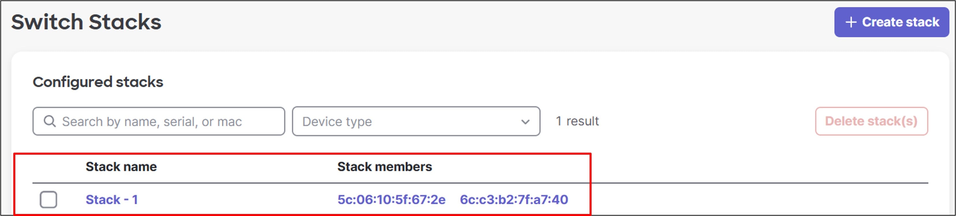
Step 3. To change the stack name, click the Stack name (Stack – 1), then click the edit symbol next to the stack name.
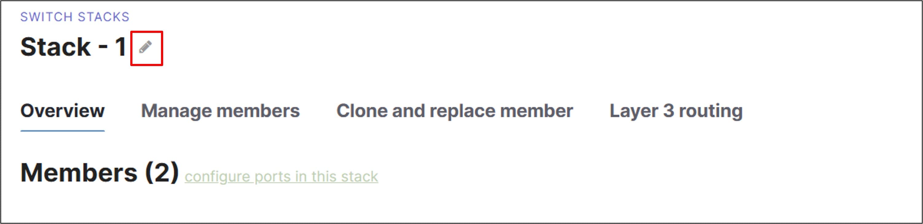
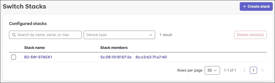
Step 4. Edit the name (B2-SW-STACK1) then click Save.
Step 5. Navigate back to the Switching > Monitor > Switch Stacks page.
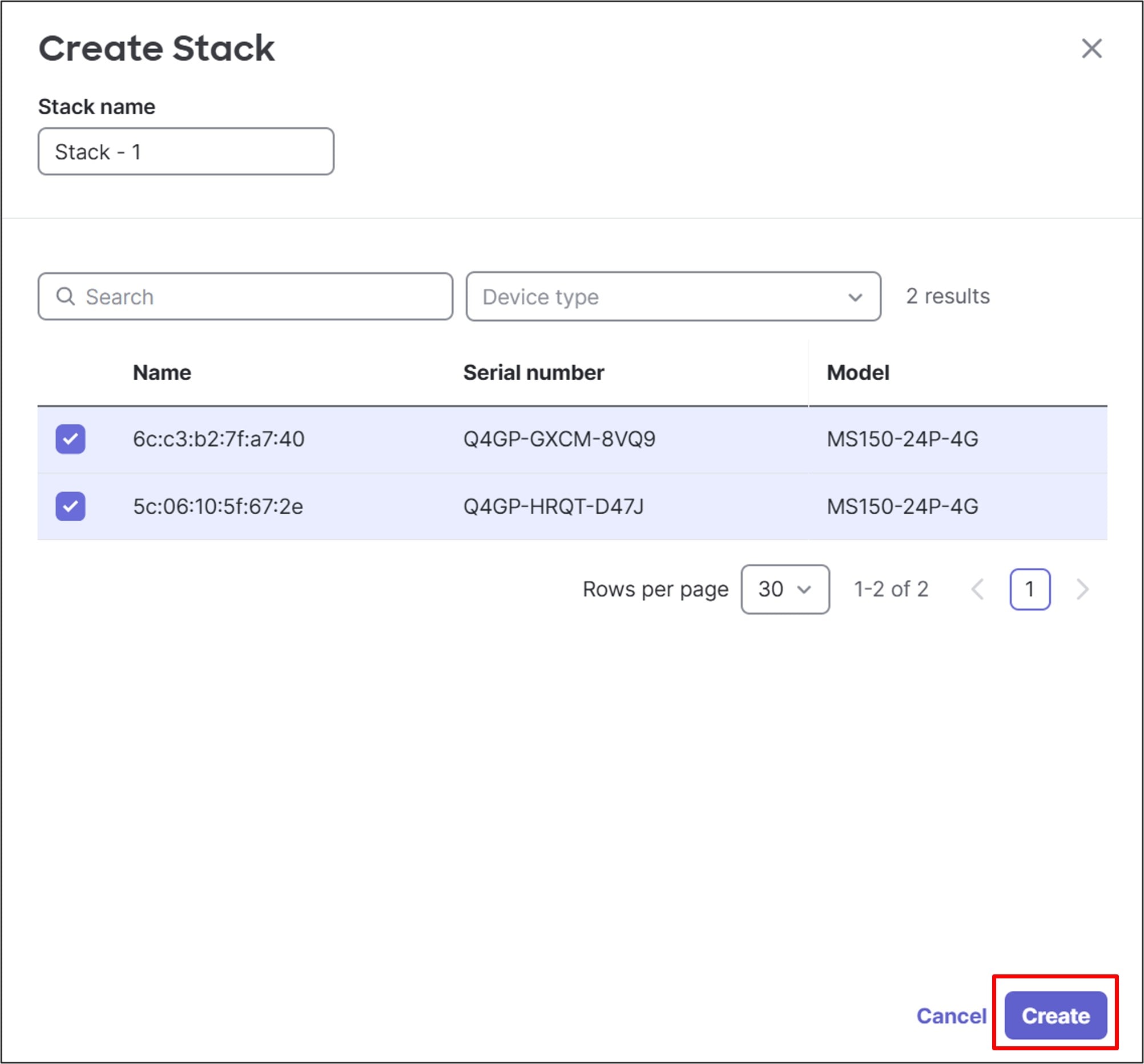
Step 6. (Optional) If the switch stack was not detected automatically, the stack can be manually created by:
a. Click Create stack.
b. Enter the Stack name.
c. Select the stack members.
d. Click Create.
Switch naming
Procedure 9. To name a switch:
Step 1. Under the new branch, go to Switching > Monitor > Switches.
Step 2. Select one of the switches.
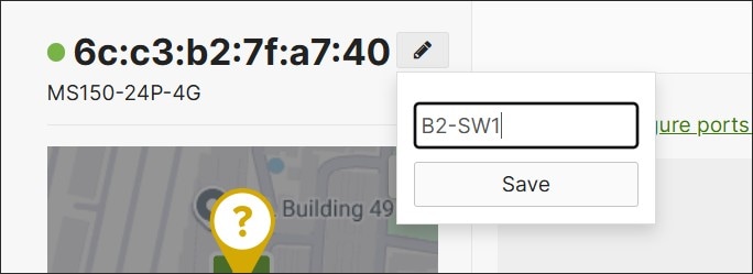
Step 3. Click the edit symbol next to the mac address in the top left corner and enter the Switch name (B2-SW1).
Step 4. Click Save.
In this example, B2-SW1 is the switch connecting to the first Internet transport and the one connecting to the AP.
Step 5. Repeat the process with the other switch (B2-SW2).
Allowed VLANs trunk configuration
By default, switches carry all VLANs on trunks.
In the MS models, the Allowed VLANs on trunks are configured as “all”, which equates to VLANs 1-4094.
In the C9300/C9200 models, allowed VLANs are represented on trunks as 1-<# of active VLANs>.
For some switch models, active VLANs are 1000. For some switches, it is less.
In the case of the 9200L-M, the number of active VLANs supported when spanning-tree is enabled is 512. VLANs above 512 cannot be added unless other VLANs are pruned off the trunks.
In this section, for any switches supporting less than 999 VLANs, all ports are configured as trunks carrying VLANs 1,10,20,30,40,50,999. Individual ports may be modified later.
Procedure 10. To modify VLANs allowed on trunk ports:
Step 1. Go to Switching > Monitor > Switch Ports. If all switches have trunks with an Allowed VLANs setting of “all”, or “1-N”, where N is greater than or equal to 999, skip to Transport configuration.
Step 2. For any switches that support active VLANS < 999, pick a switch one at a time, select all ports on the switch, then click Edit.
Step 3. Next to Allowed VLANs, type in 1,10,20,30,40,50,999 then click Update.
Note: There are no switches to update in this example.
The switch configurations should be modified to accommodate the WAN transport connections.
Procedure 11. To configure the transport VLANs:
Step 1. Go to Switching > Monitor > Switch Ports.
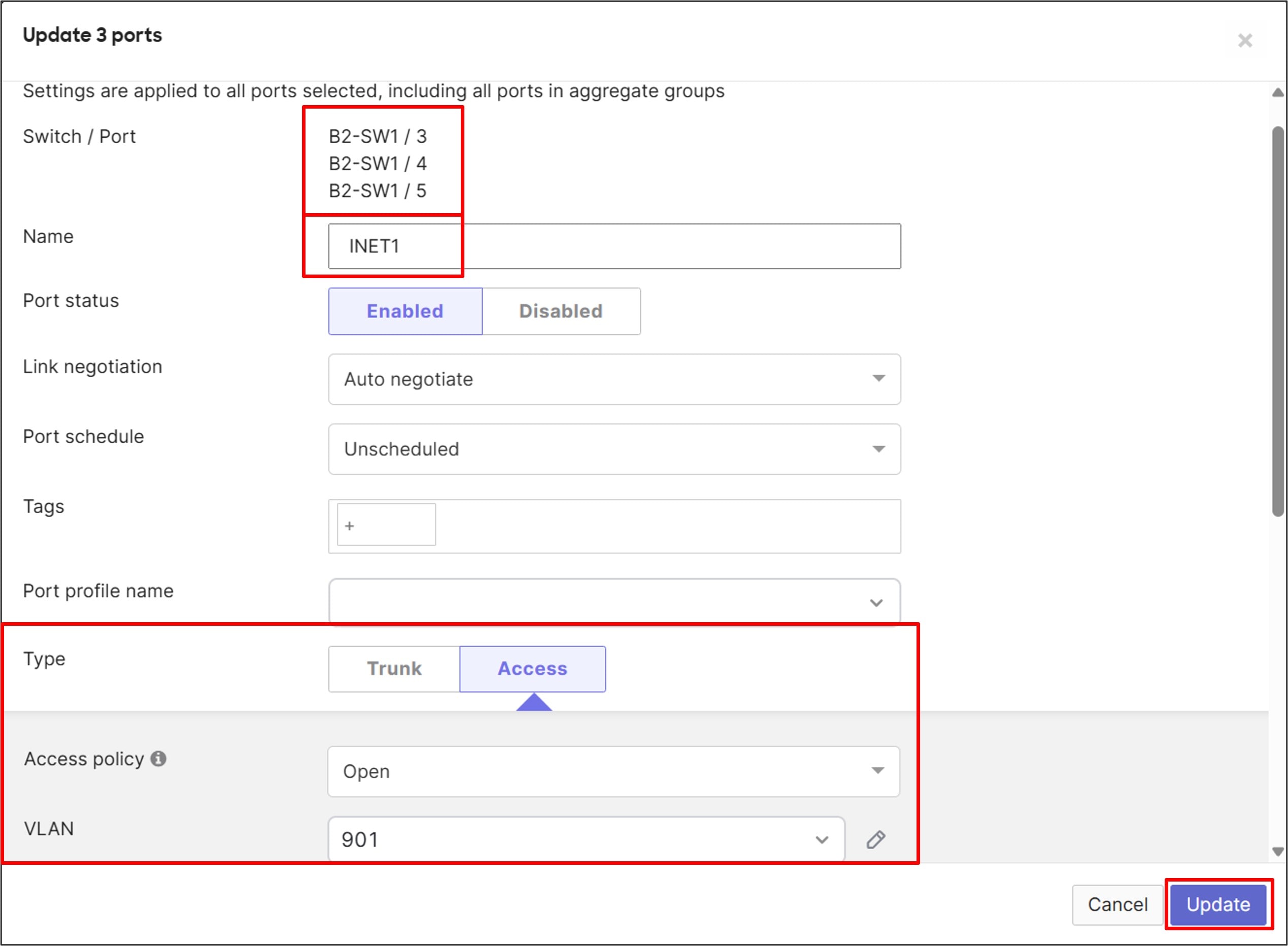
Step 2. On the switch connected to the first WAN transport (B2-SW1), select ports 3, 4, and 5, then at the top of the page, click Edit.
Step 3. Enter the Name (INET1).
Step 4. Select Type Access and enter the VLAN (901).
Step 5. Click Update.
Step 6. Remove VLAN 901 from the trunk ports going to the MX routers on B2-SW1.
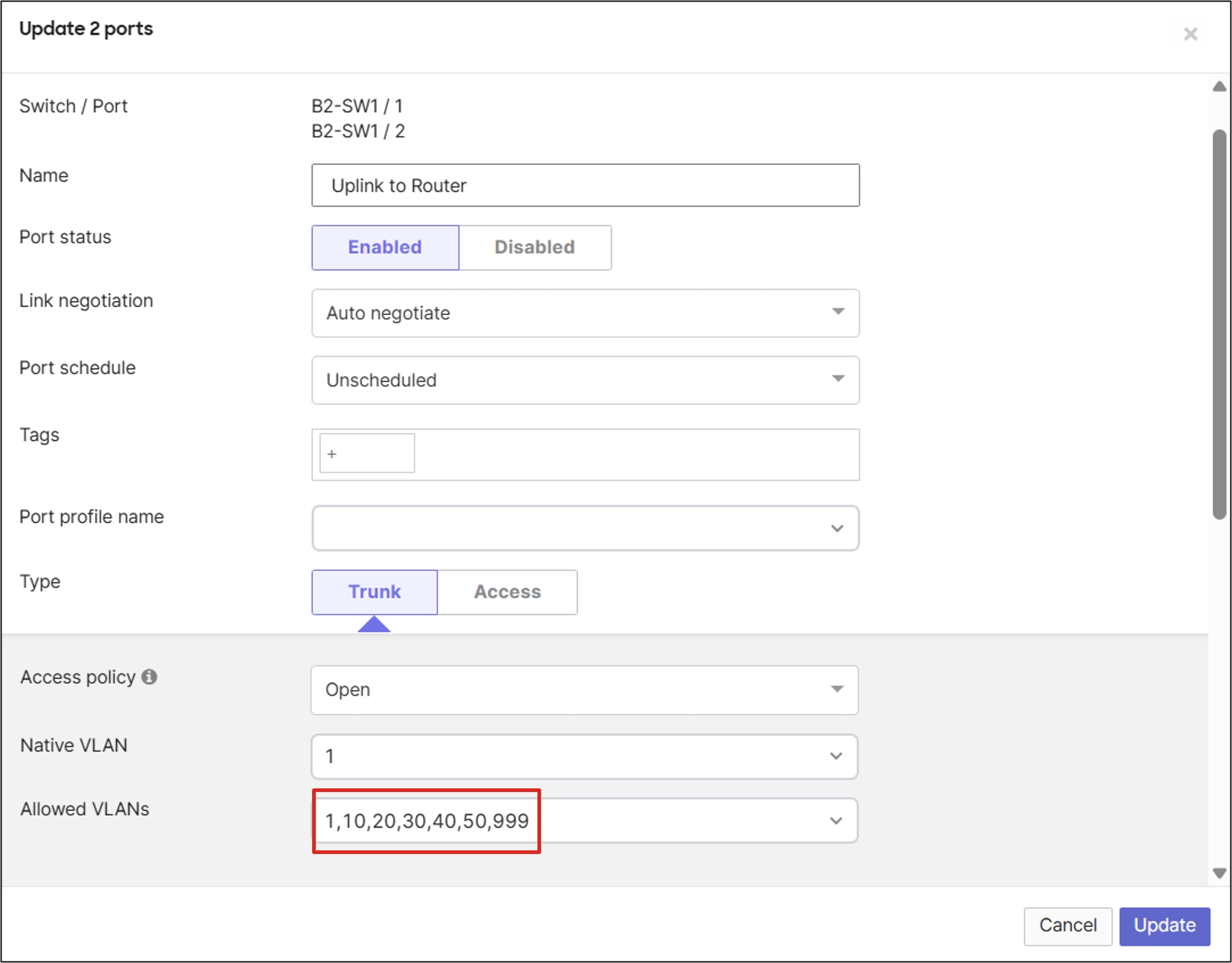
Step 7. On this same page, select ports 1 and 2, then at the top of the page, click Edit.
Step 8. Enter the Name (Uplink to Router) and next to Allowed VLANs, enter the VLANs to be configured on the MX router (1, 10, 20, 30, 40, 50, 999).
Step 9. Click Update.
Step 10. Repeat for the second switch (B2-SW2). For ports 3, 4, and 5, the port Name should be set to INET2, the Type to Access, and the VLAN to 902.
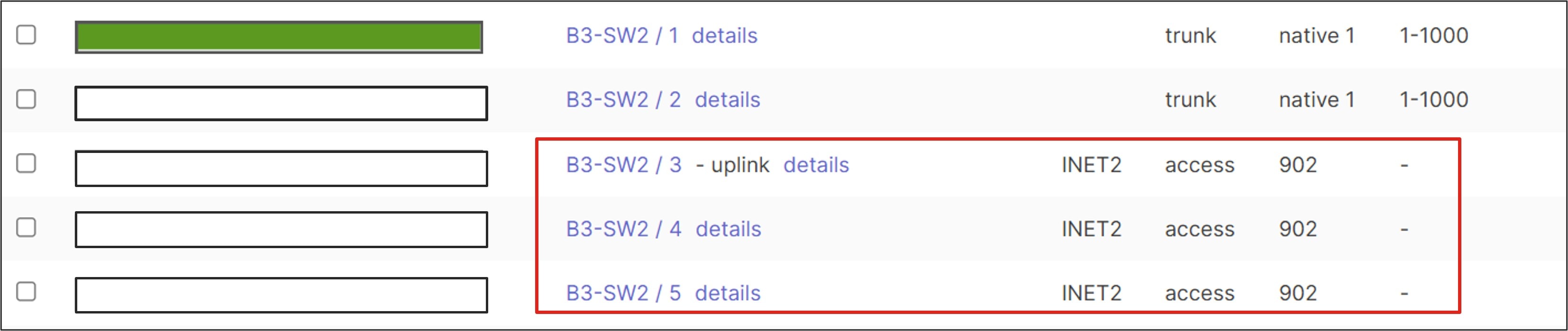
Note: To view any missing columns, click the gear in the top right corner of the column headers and select the needed category under Configuration. Click outside the box to return. Move columns as needed.
Step 11. Remove VLAN 902 from the trunk ports going to the MX routers on B3-SW2.
Step 12. On this same page, select ports 1 and 2, then at the top of the page, click Edit.
Step 13. Enter the Name (Uplink to Router) and next to Allowed VLANs, type in the VLANs to be configured on the MX router (1, 10, 20, 30, 40, 50, 999).
Step 14. Click Update.

Complete the cabling
After the switch configurations have been modified, the cabling can be completed.
Note: The spare MX router is still powered off at this point.
Procedure 12. To complete the cabling:
Transport cabling
Step 1. The switch stack is inserted between the transports and the MX routers. Move the cable from port 1 on the primary MX router to port 3 on switch 1 (B2-SW1) so switch 1 is connected to the first Internet transport provider (INET1).
Step 2. On switch 2 (B2-SW2), cable the connection from port 3 to the second Internet transport provider (INET2).
Cable these ports:
◦ Switch 1 port 4 à Primary MX router port 1
◦ Switch 1 port 5 à Spare MX router port 1
◦ Switch 2 port 4 à Primary MX router port 2
◦ Switch 2 port 5 à Spare MX router port 2
LAN cabling
The LAN cabling for the spare MX router is completed.
Step 3. Cable these ports:
◦ Switch 1 port 2 à Spare MX router port 5
◦ Switch 2 port 2 à Spare MX router port 6
Onboard the spare MX router
Note: When an MX is added to a network that already contains an active MX of the same model type, the new MX will automatically be added to the network in warm spare mode.
Procedure 13. To onboard the spare MX router
Step 1. Power the spare MX router on.
When the management traffic reaches the dashboard, a firmware upgrade may take place to update the device to the latest stable release.
When the LED on the router turns solid white, the MX is connected to the dashboard, and its default configuration should be downloaded.
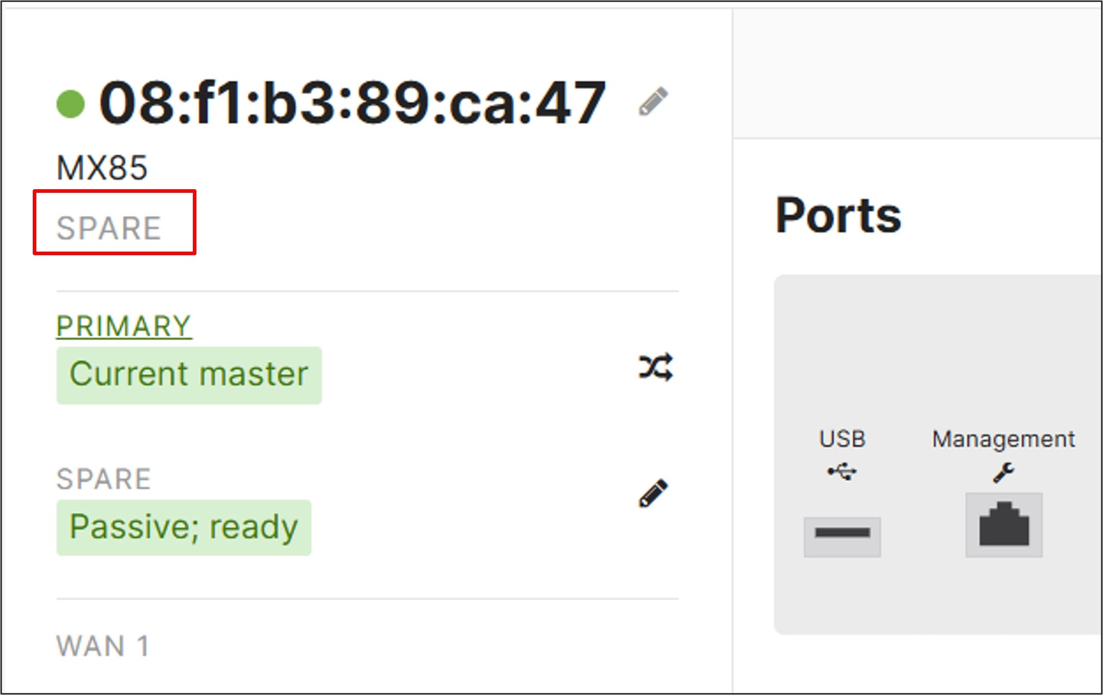
The new MX should show up in the Dashboard as a warm spare.
Step 2. View the status of the spare MX router by selecting the preferred Network (RTP6-Branch2) and going to Security & SD-WAN > Monitor > Spare Status.
Upgrade devices (if needed)
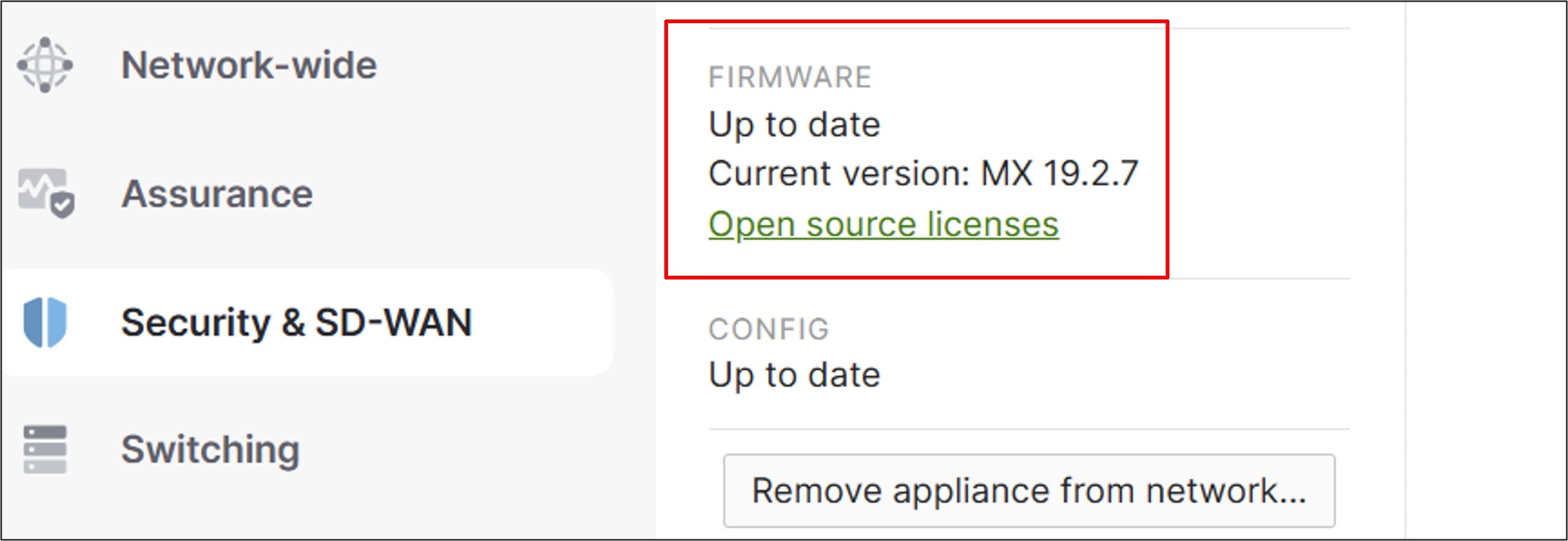
The primary and spare MX routers are upgraded to the latest stable release candidate/latest recommended version at the time of this writing (19.2.7) to pick up an additional feature (active/active tunnels for Cisco Secure Access).
Note: When selecting to upgrade the MX routers in a primary/spare pair, the routers cannot be specified separately. Both primary and spare MX routers are upgraded but steps are taken to attempt a zero-downtime MX upgrade, meaning, the primary is upgraded after the spare MX becomes active, then the spare MX is upgraded after the primary MX becomes active again.
For additional information, refer to MX Warm Spare – High-Availability Pair.
Procedure 14. To upgrade devices (if needed):
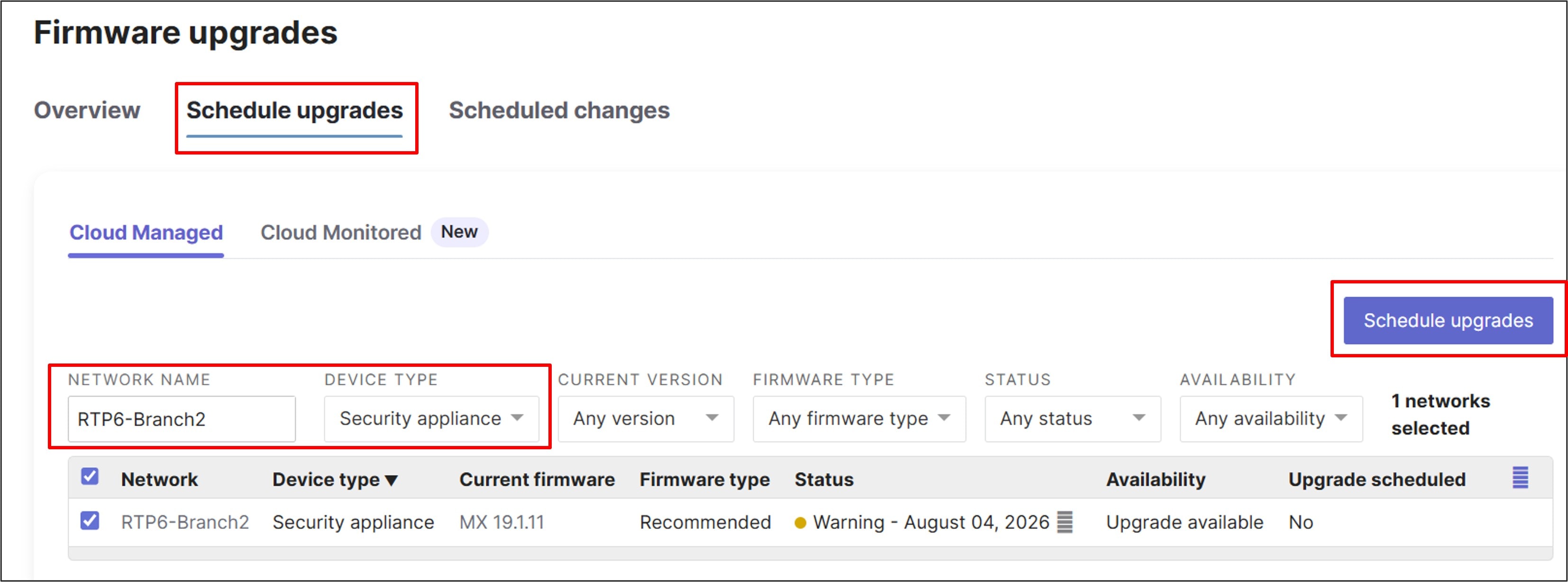
Step 1. Go to Organization > Monitor > Firmware Upgrades.
Step 2. Click the Schedule upgrades tab.
Step 3. Specify the search criteria and select the MX router to upgrade (RTP6-Branch2).
Step 4. Click Schedule upgrades.
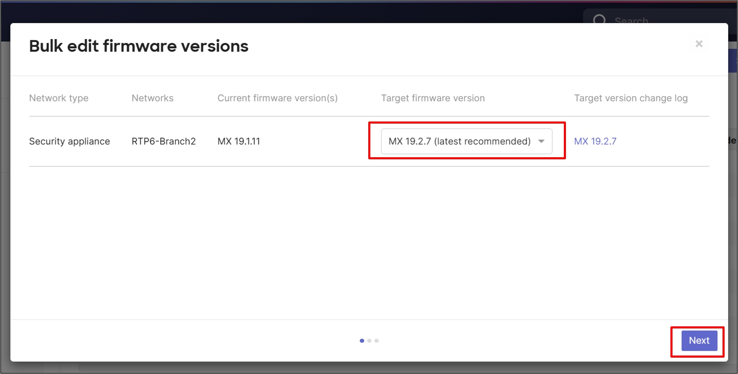
Step 5. In the next window, select the Target firmware version then click Next.
Step 6. Under Schedule firmware change, select Perform the upgrade now and click Next.
Step 7. Under Change summary, review the firmware change and select Schedule change for 1 network.
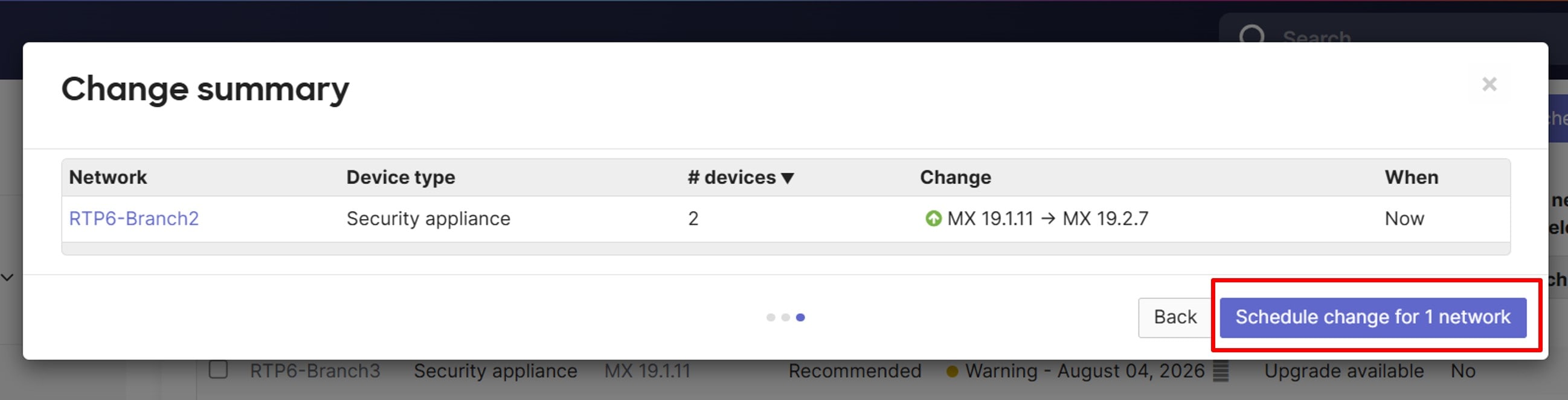
The dashboard schedules the upgrade (within 5 minutes). After the primary MX router is upgraded, the secondary MX router waits for several minutes to ensure the primary is stable before continuing with its upgrade.
Step 8. When the upgrade is complete, and both MX routers are again reachable, verify the MX version under Security & SD-WAN > Monitor > Appliance Status under the Network RTP6-Branch2.
For the MX spare version, go to Security & SD-WAN > Monitor > Spare Status.
Step 9. Go to Network-wide > Monitor > Event Log to view the network events as the devices are upgraded.
Step 10. Repeat the steps if needed for any additional devices.
In this example, the devices have already been cabled and onboarded to the Meraki Dashboard. The switches and AP use VLAN 1 to reach the dashboard through the primary MX router. In general, the network is configured in this order:
1. The network devices are named and their locations set. The time zone is configured for the network and hostname visibility is configured for traffic analysis.
2. The primary MX router is configured for a virtual uplink IP address for the WAN. It is then configured for VLANs, DHCP, site-to-site VPN settings, firewall rules, Cisco Secure Access tunnels, local Internet breakout, SD-WAN policies, traffic shaping, threat protection, and content filtering.
3. The switches and AP are then moved into the INFRA VLAN 999.
4. The switch stack is then configured for spanning-tree, Quality of Service (QoS), storm control, port access policies (802.1x/RADIUS), and the rest of the ports are then configured.
5. The wireless Guest SSID is set up, group policy is configured, corporate SSID is set up, and SSID availability and radio settings are configured.
6. Other network services are configured, such as SNMP dashboard polling and dashboard traps, syslog, SNMP device polling, and NetFlow.
7. Lastly, Adaptive Policy is configured, and ThousandEyes, Splunk, and XDR are integrated with the Merak Dashboard.
Name the devices and set the location
By default, the MXs, switches, and AP devices are named by their mac-addresses. The switch names have already been modified during the onboarding steps.
Procedure 15. To give more user-friendly names and to configure their locations:
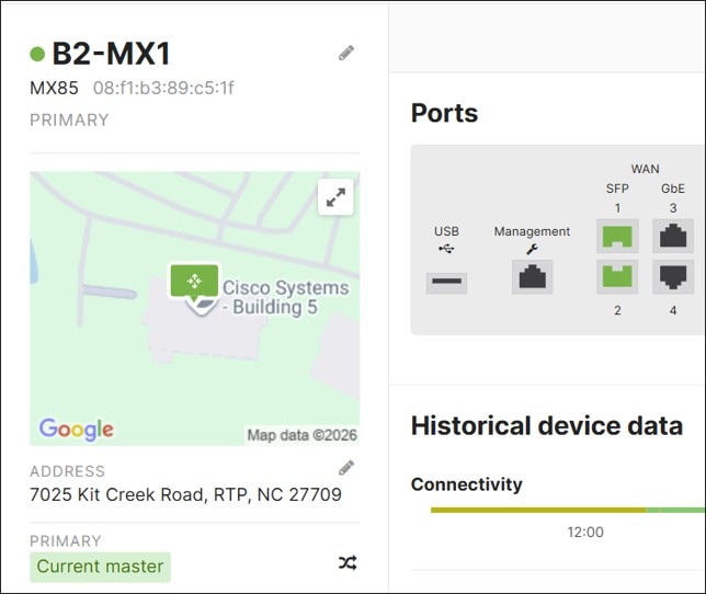
MXs: In this example, the primary is named B2-MX1 and the spare is named B2-MX2.
Step 1. Go to Security & SD-WAN > Monitor > Appliance Status.
Step 2. Click edit next to the mac address in the top left corner, and
Step 3. Enter the Appliance name (B2-MX1) then click Save.
Step 4. Next to ADDRESS, click edit, enter the street address or GPS coordinates of the location of the device, then click Save.
Step 5. Go to Security & SD-WAN > Monitor > Spare Status to name the spare MX (B2-MX2). There is no location option for the spare MX.
Switches:
Step 1. Go to Switching > Monitor > Switches.
Step 2. Select the switch name to view.
Step 3. Next to ADDRESS, click edit, enter the street address or GPS coordinates of the location of the device, then click Save.
Step 4. Repeat for the other switch.
AP:
Step 1. Go to Wireless > Monitor > Access Points.
Step 2. Select the AP mac address to view.
Step 3. In the top left corner next to the mac address, click edit.
Step 4. Enter the Access Point name (B2-AP1), then click Save.
Step 5. Next to Address, click edit.
Step 6. Enter the street address or GPS coordinates of the location of the device, then click Save.
Network-wide: Configure time zone
Time zone is used for time-sensitive features such as SSID Availability or Port Scheduling. In this example, it is used to set the schedule for SSID availability and for event logging.
In this example, America – New York (UTC -5.0) is selected.

Procedure 16. To configure a time zone:
Step 1. Go to Network-wide > Configure > General.
Step 2. Next to Local time zone, from the drop-down menu, if it’s not already configured, select the appropriate time zone.
Step 3. Click Save or Save Changes.
Network-wide: Configure traffic analysis settings
In this section, hostname visibility is enabled under Traffic Analysis settings. Activating hostname visibility provides detailed statistical insights into the hostnames and IP addresses accessed by clients across the network. When configured, the menu item Network-wide > Monitor > Traffic Analytics appears in the dashboard. Information can also be accessed under Network-wide > Monitor > Clients.
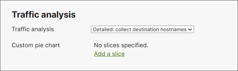
Procedure 17. To activate hostname visibility:
Step 1. Go to Network-wide > Configure > General.
Step 2. From the drop-down menu under Traffic analysis, select Detailed: collect destination hostnames.
Step 3. Click Save or Save Changes.
MX router: Configure warm spare uplink IP
By default, when the warm spare becomes active, it leverages its own WAN uplink IP addresses that were configured or received from DHCP from the transport provider. There is an option to use a virtual uplink IP address on each transport, so when the warm spare takes over, the same virtual IP address becomes active on the spare. The virtual IP addresses must be within the same subnet but must be distinct from the appliance WAN uplink IP addresses. This reduces traffic convergence time during a failover.
Procedure 18. To configure warm spare uplink IP address:
Step 1. Go to Security & SD-WAN > Monitor > Appliance Status. Next to Spare, click the Edit icon.
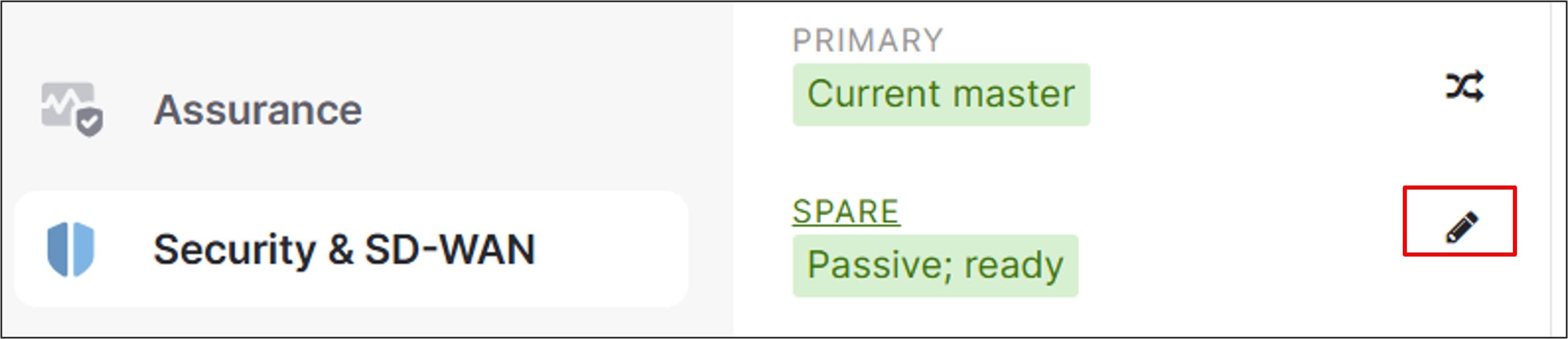
Step 2. Next to Uplink IPs, from the drop-down menu, select Use virtual uplink IPs.
Step 3. Next to WAN 1 shared IP, type in the virtual IP address for the first WAN transport.
Step 4. Next to WAN 2 shared IP, type in the virtual address for the second transport.
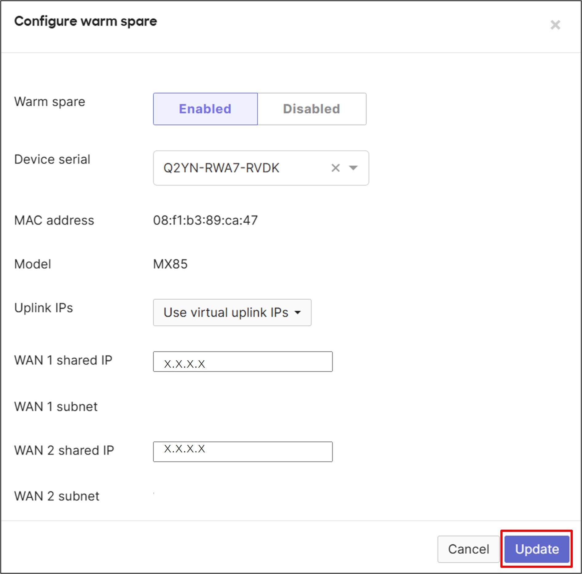
Step 5. Click Update.
MX router: Configure VLAN interfaces
Procedure 19. To configure VLAN interfaces:
Step 1. Under Security & SD-WAN > Configure > Addressing & VLANs > Routing > LAN setting, select VLANs. VLAN 1 is automatically created with a VLAN interface IP of 192.168.128.1/24.
Step 2. In the Subnets section, click Add VLAN. Enter VLAN name (DATA) and VLAN ID (10).
Step 3. Next to VLAN interface IP, enter the IP address of the MX gateway address for VLAN 10 (DATA) (10.10.2.1).
This is in the form 10.<VLAN#><SITE#>.1 so global firewall rules for site-to-site VPNs can be efficiently applied.
Step 4. Next to Subnet, enter the VLAN subnet (10.10.2.0/24), then click Create.
Step 5. Click Save, which may be at the bottom of the page.
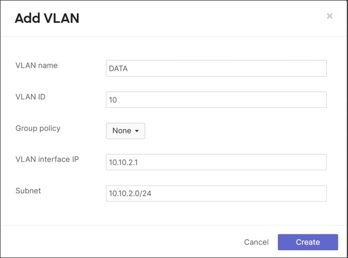
Step 6. Repeat the steps to add additional VLANs for 20 (VOICE), 30 (IOT), 40 (PCI), 50 (GUEST), and INFRA (999).
The VLAN 1 interface IP address is left at default (192.168.128.1) and the VLAN 999 (INFRA) interface IP address is configured as 10.250.<site#>.1. The VLANs 10, 20, 30, and 40 interface IPs follow the scheme 10.<VLAN#><Site#>.1. Site # in this example is 2. All subnets are /24 masks. All guest traffic on all branches shares the same subnet (172.16.99.0/24), and the GUEST VLAN interface IP address is configured for 172.16.99.1.
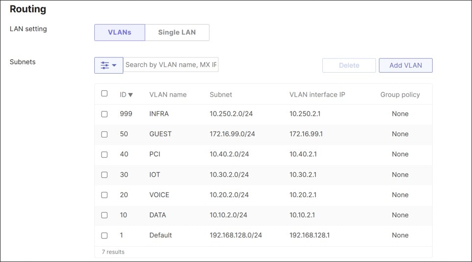
Step 7. Click Save, which may be at the bottom of the page.
MX router: Modify unused ports
Procedure 20. To modify unused ports:
Step 1. Navigate to Security & SD-WAN>Configure>Addressing & VLANs under Per-port VLAN Settings.
Step 2. Select the unused ports (ports 7-14 in this case) and click Edit.
Step 3. Next to Enabled, from the drop-down menu, select Disabled.
Step 4. Click Update.
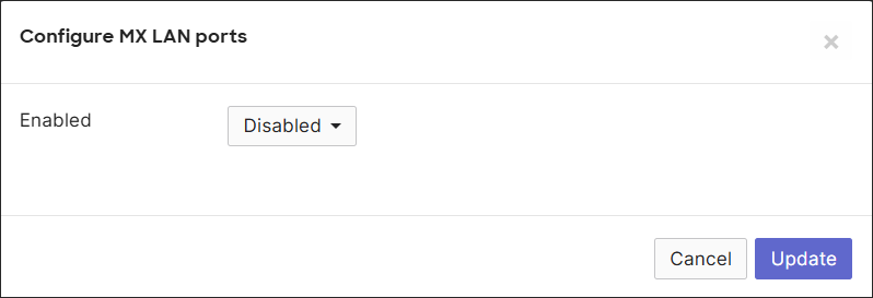
Step 5. Click Save.
MX router: Modify VLANs allowed on trunks
Procedure 21. To modify VLANs allowed on trunks:
Step 1. Under the Per-port VLAN Settings, there are two trunk ports (ports 5 and 6), one to B2-SW1 and one to B2-SW2. Select ports 5 and 6 and click Edit.
Step 2. Next to Allowed VLANs, delete All VLANs or Existing Values.
Step 3. From the drop-down menu, select VLAN 1 (Default), VLAN 10 (DATA), VLAN 20 (VOICE), VLAN 30 (IOT), VLAN 40 (PCI), VLAN 50 (GUEST), and VLAN 999 (INFRA), then click Update.
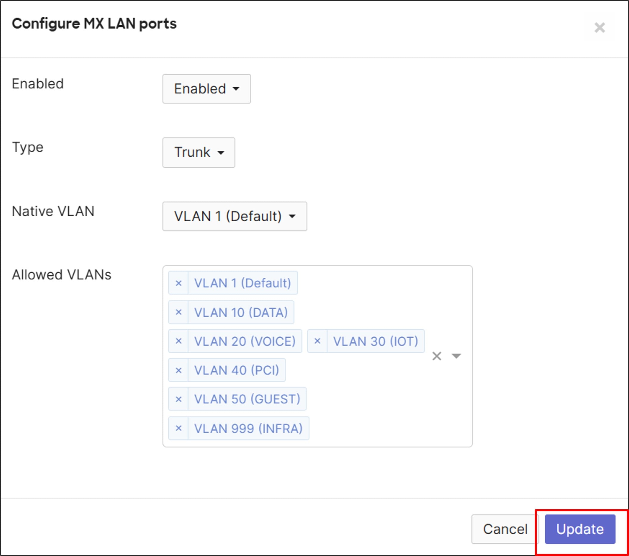
Step 4. Click Save.
MX router: Configure DHCP
By default, All DHCP pools are local and proxy to an upstream DNS, which is out on the Internet transport.
In this network, the Default, INFRA, and GUEST VLANs use local DHCP pools, while the other subnets use DHCP services in the data center. INFRA devices use reserved IP addresses from the DHCP pool. Only GUEST and Default VLANs should use an Internet DNS server (OpenDNS), while everything else uses DNS services in the data center.
Tech tip: For MS switch stacks (except for MS390), each stack member receives its own IP address using its burned-in mac address (Switching > Monitor > Switches > MAC address). For Catalyst switch stacks running CS code and the MS390, each stack member shares a single IP address with the active member, and the stack leverages the burned-in mac address of the active member that is persistent when a new member takes over. For Catalyst switch stacks running IOS XE code, each stack member also shares a single IP address with the active member, but the stack leverages a single virtual mac address of the form, 00:18:0a:4f:00:XX. To find the mac address used for switch stack management, go to Security & SD-WAN > Monitor > Appliance Status. Click the DHCP tab and search for the device which should have received an IP address in VLAN 1.
Ideally, management IP addresses should be statically configured and their addresses excluded from the DHCP pool. Due to limitations in automation at this time, DHCP has to be leveraged for IP assignment. Fixed IP address assignments in the DHCP pool allow devices to use DHCP to get an address but ensure those devices get the same IP address each time. A device mac address is needed for the configuration.
Because IOS XE switch stacks use a virtual mac address, a new mac address could potentially be generated on complete power down and power back up of the entire switch stack (depending on what might be going on with other IOS XE switch stacks in the network at the time). The algorithm ensures that no other network devices share the same virtual mac address. If the mac address changes, the switch stack will receive a new management IP address from the DHCP pool instead of the one that was initially assigned.
Before configuring this section, gather the mac addresses from any access points and all switches and switch stacks so fixed IP address assignments can be created.
| Device |
Dashboard location |
Mac address |
| B2-SW1 |
Switching>Monitor>Switches>MAC address |
6c:c3:b2:7f:a7:40 |
| B2-SW2 |
Switching>Monitor>Switches>MAC address |
5c:06:10:5f:67:2e |
| B2-AP1 |
Wireless>Monitor>Access Points>MAC address |
cc:6e:2a:d8:9b:10 |
Procedure 22. To configure DHCP:
Step 1. Go to Security & SD-WAN > Configure > DHCP and under VLAN 999 (INFRA) next to DNS nameservers, select Specify nameservers.
Step 2. Next to Custom nameservers, type in the DNS servers at the data center (10.102.1.160 and 10.102.1.161 in this example).
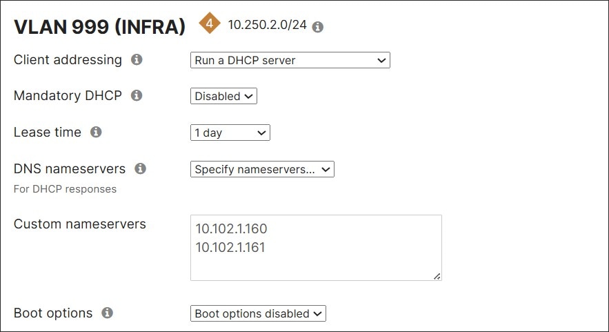
Step 3. Next to Fixed IP assignments, click Add a fixed IP assignment.
Step 4. Enter a name for the device, the mac address, and what LAN IP address is to be assigned.
Step 5. Repeat for all devices.
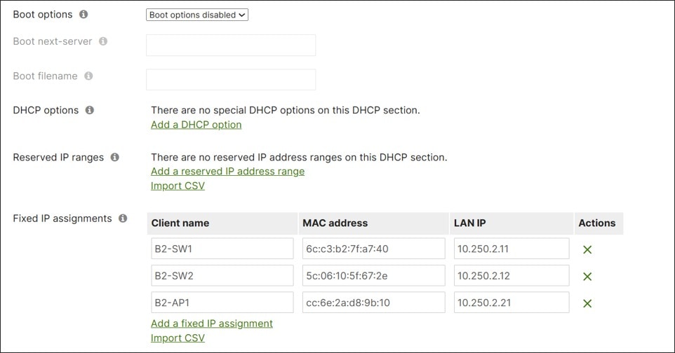
Step 6. Click Save Changes at the bottom of the page.
Step 7. For VLANs 10, 20, 30, and 40, next to Client addressing, select Relay DHCP to another server and next to DHCP server IPs, type in the data center DHCP servers (10.102.1.160 and 10.102.1.161 in this example).
Step 8. Click Save or Save Changes.
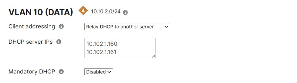
Tech tip: The DHCP relay IP address must be in a subnet connected to the network or on a subnet reachable through the site-to-site VPN (not through the default route). In the example data center, there is a static route defined to reach the DC services network, and that static route is in VPN mode so it can be advertised to other Auto VPN members.
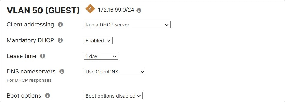
Step 9. For the GUEST VLAN (50) and Default VLAN (1), next to Mandatory DHCP, from the drop-down menu, select Enabled.
Step 10. Next to DNS nameservers, from the drop-down menu, select Use OpenDNS.
Step 11. Click Save or Save Changes.
MX router: Configure site-to-site VPNs
Hub and spoke settings
Procedure 23. To configure hub and spoke settings:
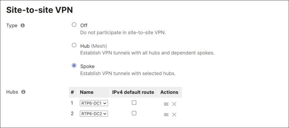
Step 1. Under Security & SD-WAN > Configure > Site-to-site VPN, next to Type, select Spoke.
Step 2. Next to Hubs, click Add a hub and select the primary hub (RTP6-DC1 in this example).
Step 3. Click Add a hub and select the secondary hub (RTP6-DC2 in this example). Since DC1 was selected first, this prioritizes DC1 as the primary hub, so if routes are equal, DC1 is selected to route the traffic.
Step 4. Click Save or Save Changes.
VPN settings for VLANs
By default, subnets are not advertised to other sites through the VPN registry.
Procedure 24. To configure VPN settings for VLANs:
Step 1. Under Security & SD-WAN > Configure > Site-to-site VPN, under VPN settings > Local networks, choose Enabled under VPN mode for DATA, VOICE, IOT, PCI, and INFRA so these networks can be advertised.
Step 2. Click Save or Save Changes.

MX router: Configure firewall rules
VPN site-to-site outbound firewall
The VPN site-to-site outbound firewall rules apply to outbound VPN traffic destined to other VPN-connected sites and is applied at an organization level, meaning, these same rules apply to every MX router in the organization with site-to-site VPN enabled. This is important as it influences the way the rules should be crafted. In the example network, the network scheme is 10.<vlan#><site#>.0/24 so firewall rules can be applied more easily at the organizational level. The Data VLAN across the organization is represented by the subnet 10.10.0.0/16 instead of a list of disjointed 10.x networks.
If the policy objects and VPN site-to-site outbound firewall policy are already defined, go to Local firewall.
For the VPN site-to-site outbound firewall rules, only policy objects, policy object groups, IPv4/IPv6 addresses, or subnets can be referenced. The following policy is implemented:
● Allow the DATA, VOICE, IOT, PCI, and INFRA subnets in any branch to reach Corporate shared services (DHCP, DNS, RADIUS, SNMP, and Management) and allow Corporate shared services to reach the DATA, VOICE, IOT, PCI, and INFRA subnets in any branch.
● Deny access from DATA, VOICE, IOT, PCI, and INFRA subnets to other subnets in other sites. Meaning, DATA subnets cannot reach VOICE, IOT, PCI, and INFRA subnets, and so on.
● Allow everything else. This is the default rule and allows DATA subnets to reach other DATA subnets as well as other routes through the hub. VOICE subnets can reach other VOICE subnets as well as other routes through the hub, and so on.
Note: Guest and Default traffic do not traverse the VPN overlay due to VPN mode being disabled for these VLANs. They can be included in the rule as “Deny GUEST subnet or Default subnet to Any” and “Deny Any to GUEST subnet or Default subnet” if needed, in the event the GUEST or Default VLAN’s VPN mode is enabled, and a unique subnet is configured.
Policy, or network, objects and groups provide easier management of firewall rules. They serve as labels for IP subnets, IP addresses, or FQDNs. Policy groups contain one or more IP/CIDR network objects or one or more FQDN network objects. When created, these objects and groups can be used in both side-to-site VPN outbound firewall rules as well as Layer 3 inbound/outbound firewall rules. Policy objects and groups are defined at the organization level.
Procedure 25. To configure policy objects and VPN site-to-site outbound firewall rules:
Step 1. Go to Organization > Configure > Policy Objects.
Step 2. Under the All objects tab, click Add new.
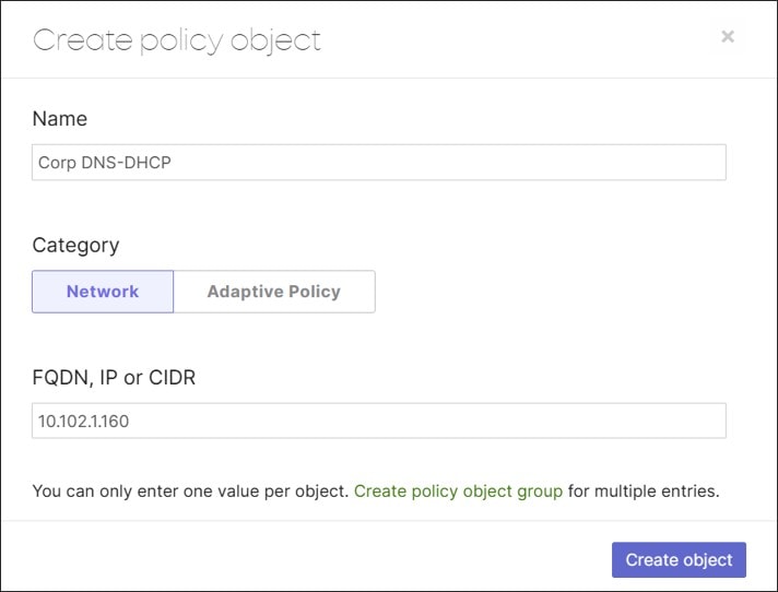
Step 3. Under Name, type in a name (Corp DNS-DHCP in this example) and under FQDN, IP or CIDR, add an IP host (10.102.1.160 in this example), then click Create object.
Step 4. After the objects are created, go to the Groups tab to create a grouping. In this example, a Corp Shared Services group is created for the various network services sitting in the data center.
Note: Objects within policy groups can be created before the policy group object is created or while the policy group object is being defined.
Step 5. Create these objects and object group. GUEST and Default subnet is leveraged by the layer 3 local firewall rules in a subsequent section.
| Object or Object Group |
Name |
Category |
FQDN, IP, or CIDR |
| Object |
Corp DNS-DHCP |
Network |
10.102.1.160 |
| Object |
Corp Mgt |
Network |
10.102.1.160 |
| Object |
Corp SNMP |
Network |
10.102.1.161 |
| Object |
Corp RADIUS |
Network |
10.102.1.157 |
| Object |
DATA Subnet |
Network |
10.10.0.0/16 |
| Object |
Default Subnet |
Network |
192.168.128.0/24 |
| Object |
GUEST Subnet |
Network |
172.16.99.0/24 |
| Object |
INFRA Subnet |
Network |
10.250.0.0/16 |
| Object |
IOT Subnet |
Network |
10.30.0.0/16 |
| Object |
PCI Subnet |
Network |
10.40.0.0/16 |
| Object |
VOICE Subnet |
Network |
10.20.0.0/16 |
| Object Group |
Corp Shared Services |
-- |
Corp DNS-DHCP/Corp Mgt/Corp SNMP/Corp RADIUS |
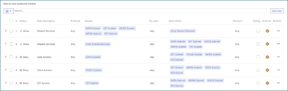
Step 6. Go to Security & SD-WAN > Configure > Site-to-Site VPN, and under Site-to-site outbound firewall, configure these settings:
| Policy |
Rule description |
Protocol |
Source |
Src port |
Destination |
Dst port |
| Allow |
Shared Services |
Any |
DATA Subnet/VOICE Subnet/IOT Subnet/PCI Subnet/INFRA Subnet (Objects) |
Any |
Corp Shared Services (Object group) |
Any |
| Allow |
Shared Services |
Any |
Corp Shared Services (Object group) |
Any |
DATA Subnet/VOICE Subnet/IOT Subnet/PCI Subnet/INFRA Subnet (Objects) |
Any |
| Deny |
Data Access |
Any |
DATA Subnet (Object) |
Any |
VOICE Subnet/PCI Subnet/IOT Subnet/INFRA Subnet (Objects) |
Any |
| Deny |
Voice Access |
Any |
VOICE Subnet (Object) |
Any |
DATA Subnet/IOT Subnet/PCI Subnet/INFRA Subnet (Objects) |
Any |
| Deny |
IOT Access |
Any |
IOT Subnet (Object) |
Any |
DATA Subnet/VOICE Subnet/PCI Subnet/INFRA Subnet (Objects) |
Any |
| Deny |
PCI Access |
Any |
PCI Subnet (Object) |
Any |
DATA Subnet/VOICE Subnet/IOT Subnet/INFRA Subnet (Objects) |
Any |
| Deny |
Infra Access |
Any |
INFRA Subnet (Object) |
Any |
DATA Subnet/VOICE Subnet/IOT Subnet/PCI Subnet (Objects) |
Any |
| Allow |
Default Rule |
Any |
Any |
Any |
Any |
Any |
Step 7. Click Finish editing.
Step 8. Click Save Changes.
Local firewall rules apply to LAN traffic as well as direct Internet traffic. It does not apply to VPN site-to-site traffic.
Tech tip: VLAN objects can be leveraged automatically in local firewall rules in single MX deployments but are not available to use in VPN site-to-site outbound firewall rules.
VLAN objects used in firewall rules are not compatible with the MX warm spare feature. If VLAN objects are used in firewall rules and an MX warm spare is added to the network, any existing layer 3 rules referencing VLAN objects are removed.
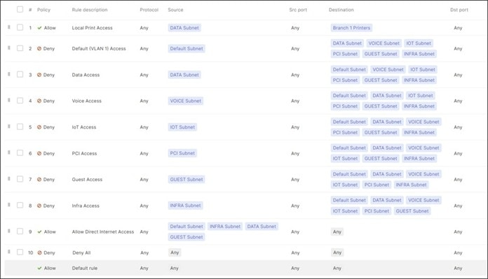
The layer 3 policy will leverage the policy objects created for the VPN site-to-site outbound firewall rules. These policy objects can be leveraged at all branches. The following policy is implemented.
● Allow the Data subnet to access local Printers (10.30.2.101 and 10.30.2.102) on the IOT subnet. The Layer 3 firewall rules are stateful, so traffic in the opposite direction is allowed back through.
● Deny access from Default, DATA, VOICE, IOT, PCI, GUEST, and INFRA subnets to other subnets at the same site. Meaning, DATA subnets cannot reach Default, VOICE, IOT, PCI, GUEST, and INFRA subnets, and so on.
● Allow direct Internet access (DIA) for Default, INFRA, DATA, and GUEST subnets. Default and GUEST subnet traffic strictly uses DIA. For the INFRA subnet, dashboard traffic for devices behind the MX uses DIA. For the DATA subnet, Webex and Office 365 traffic uses DIA while the rest of the DATA subnet traffic leverages Cisco Secure Access for Internet traffic.
● Deny everything else. This does not affect VPN site-to-site traffic, which is governed by site-to-site VPN firewall rules. This means that VOICE, IOT, and PCI subnets will be denied DIA.
Tech tip: When a default route is configured from the hub router or through Cisco Secure Access (as in this example), the MX is in full tunnel mode. In order for DIA to occur, VPN exclusions identifying traffic to be broken out must be configured (shown later in this example, under Security & SD-WAN > Configure > SD-WAN & Traffic Shaping). When broken out for DIA, this traffic is subjected to local firewall rules. These rules do not affect traffic going to Cisco Secure Access. VPN exclusions are configured based on IP destination or application. It is important to design the firewall rules carefully so they are not more restrictive than the defined VPN exclusions (unless that is needed), as this could unexpectedly blackhole traffic. For example, excluding ICMP with a destination of 8.8.8.8 sends all ICMP traffic regardless of the source VLAN with a destination of 8.8.8.8 to DIA. If the firewall blocks IOT traffic from DIA, ICMP traffic to 8.8.8.8 from the IOT VLAN is dropped. If this traffic should go to Cisco Secure Access, ensure it is not configured in VPN exclusions.
Policy objects and a group can be optionally created for the branch printers.
Procedure 26. To configure policy objects and configure local firewall rules:
Step 1. Create these objects and group under Organization > Configure > Policy Objects:
| Object or Object Group |
Name |
Category |
FQDN, IP, or CIDR |
| Object |
Branch 2 Printer 1 |
Network |
10.30.2.101 |
| Object |
Branch 2 Printer 2 |
Network |
10.30.2.102 |
| Object Group |
Branch 2 Printers |
--- |
Branch 2 Printer 1/Branch 2 Printer 2 |
Step 2. Select Security & SD-WAN > Configure > Firewall and under Layer 3 > Outbound rules, click Add new.
Step 3. Fill out the parameters and click Add new to add the next rule as shown in this table:
| Rule Description |
Protocol |
Source |
Src port |
Destination |
Dst Port |
|
| Allow |
Local Print Access |
Any |
DATA Subnet (Object) |
Any |
Branch 1 Printers (Object group) |
Any |
| Deny |
Default (VLAN 1) Access |
Any |
Default Subnet (Object) |
Any |
DATA Subnet/VOICE Subnet/IOT Subnet/PCI Subnet/GUEST Subnet/INFRA Subnet (Objects) |
|
| Deny |
Data Access |
Any |
DATA Subnet (Object) |
Any |
Default Subnet/VOICE Subnet/IOT Subnet/PCI Subnet/GUEST Subnet/INFRA Subnet (Objects) |
Any |
| Deny |
Voice Access |
Any |
VOICE Subnet (Object) |
Any |
Default Subnet/DATA Subnet/IOT Subnet/PCI Subnet/GUEST Subnet/INFRA Subnet (Objects) |
Any |
| Deny |
IOT Access |
Any |
IOT Subnet (Object) |
Any |
Default Subnet/DATA Subnet/VOICE Subnet/PCI Subnet/GUEST Subnet/INFRA Subnet (Objects) |
Any |
| Deny |
PCI Access |
Any |
PCI Subnet (Object) |
Any |
Default Subnet/DATA Subnet/VOICE Subnet/IOT Subnet/GUEST Subnet/INFRA Subnet (Objects) |
Any |
| Deny |
Guest Access |
Any |
GUEST Subnet (Object) |
Any |
Default Subnet/DATA Subnet/VOICE Subnet/IOT Subnet/PCI Subnet/INFRA Subnet (Objects) |
|
| Deny |
Infra Access |
Any |
INFRA Subnet (Object) |
Any |
Default Subnet/DATA Subnet/VOICE Subnet/IOT Subnet/PCI Subnet/GUEST Subnet (Objects) |
|
| Allow |
Allow Direct Internet Access |
Any |
Default Subnet (Object)/INFRA Subnet (Object)/DATA Subnet (Object)/GUEST Subnet (Object) |
Any |
Any |
Any |
| Deny |
Deny All |
Any |
Any |
Any |
Any |
Any |
| Allow |
Default rule |
Any |
Any |
Any |
Any |
Any |
Step 4. When complete, click Finish editing, then Save or Save Changes.
Cisco Secure Access and MX router: Configure secure internet access tunnels
Secure tunnels are configured with Cisco Secure access and the MX router for branch direct Internet access.
Note: Wehn the tunnels are set up in the Meraki Dashboard to a particular network tunnel group in Cisco Secure Access, the configurations are available in the Meraki Dashboard at the organizational level for other branches to leverage. To leverage an existing secure tunnel pair, the branch is tagged in the Organization > Monitor > Overview page using the same tag attached to the IPsec tunnel pair when created (SSE_East in this example). No additional configuration is required.
These steps show how to tag a branch to leverage a Cisco Secure Access tunnel pair, set up a network tunnel group in Cisco Secure Access and subsequently, configure the primary and secondary IPsec tunnel pairs in the Meraki Dashboard to connect to that network tunnel group if not already configured.
If Cisco Secure Access tunnels pairs are already set up, configure the network tag for the preferred branch and skip the tunnel configuration in Cisco Secure Access and on the MX router.
Organization level: Tag the branch to leverage Cisco Secure Access tunnels
In this example, a tag called “SSE_East” is selected/created in the Dashboard to reference an active/standby tunnel pair that exists or will be configured, connecting Branch 2 to Cisco Secure Access.
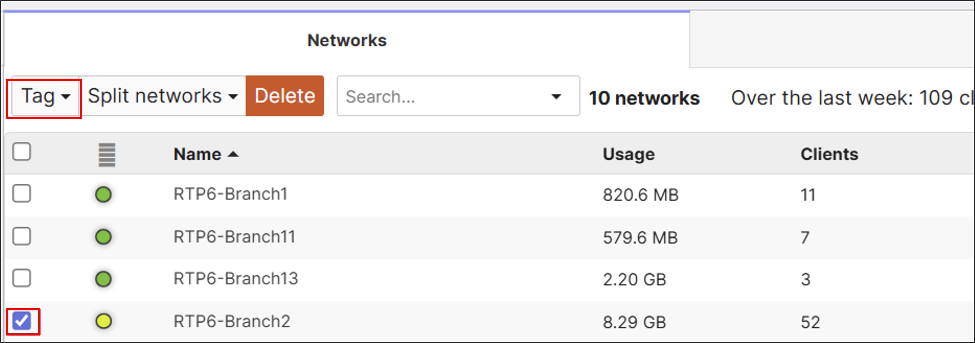
Procedure 27. To tag the branch to leverage Cisco Secure Access tunnels:
Step 1. On the Meraki Dashboard, navigate to Organization > Monitor > Overview.
Step 2. Select the branch network (RTP6-Branch2) then click Tag.
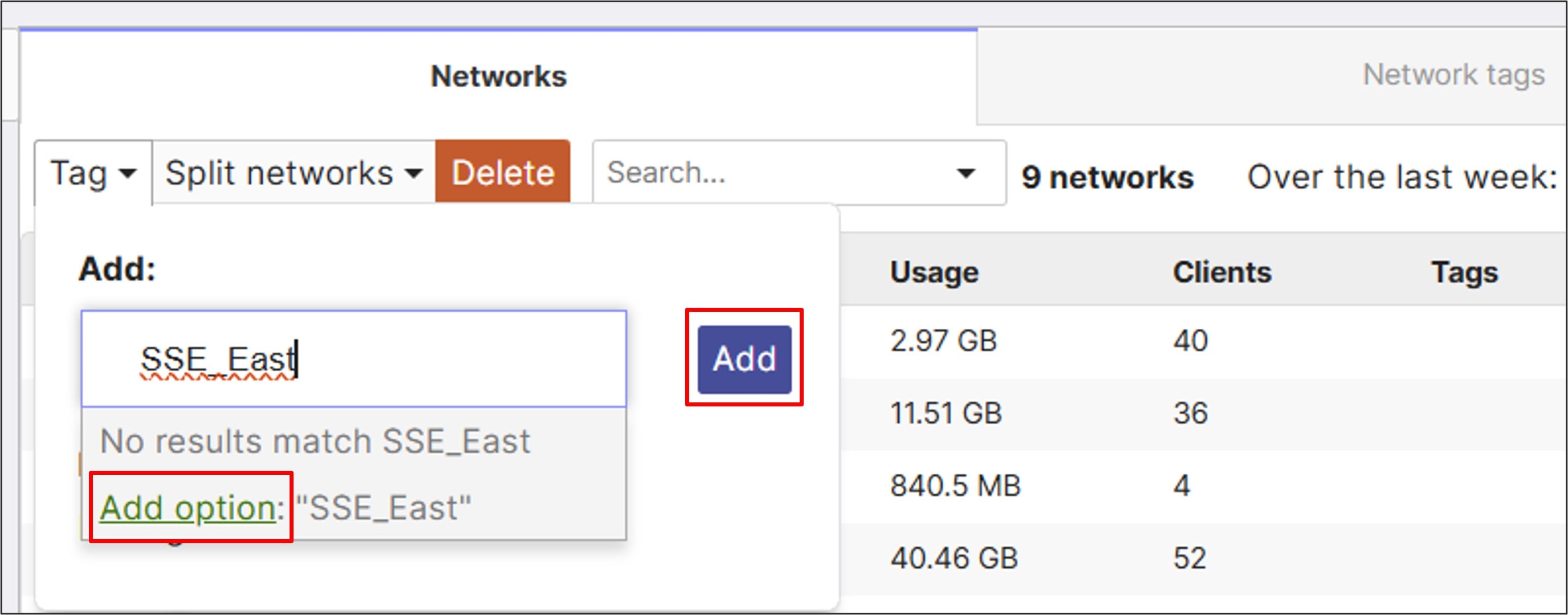
Step 3. In the text box, select the existing tag, SSE_East, then click Add.
If the tag has not been created yet, type in the new tag (SSE_East), click Add option beneath the text box, then click Add.
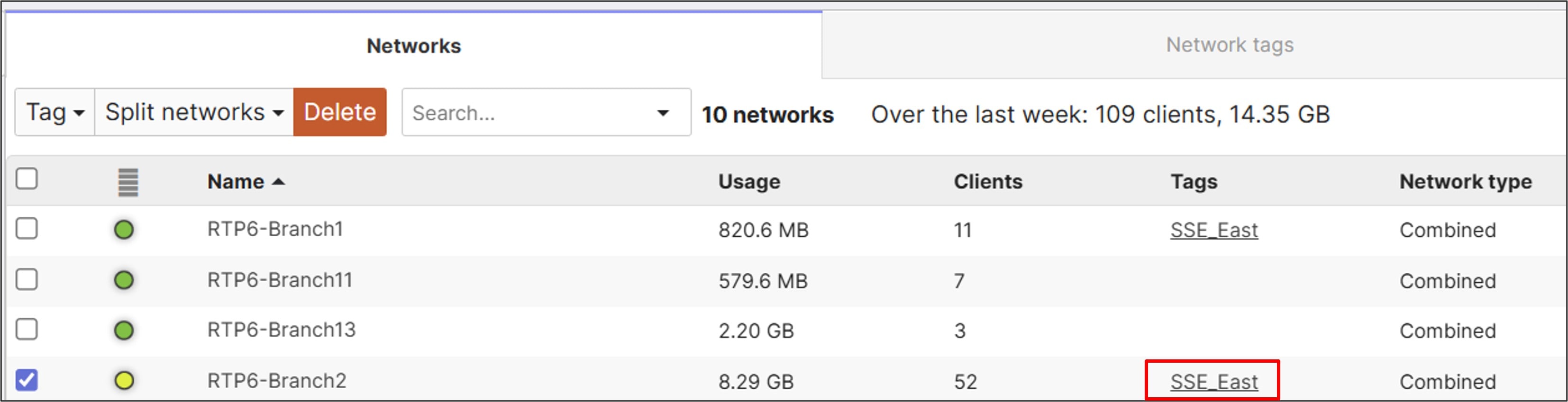
Branch 2 now has an SSE_East tag.
Step 4. If SSE tunnels are already configured, skip to the Validate Status of Cisco Secure Access Tunnels section to check the tunnel status.
Cisco Secure Access: Tunnel configuration
Procedure 28. To configure a Network Tunnel Group on Cisco Secure Access:
Step 1. Go to https://sse.cisco.com and log in with the proper credentials.
Step 2. From Cisco Secure Access, go to Connect > Network Connections > Network Tunnel Groups tab.
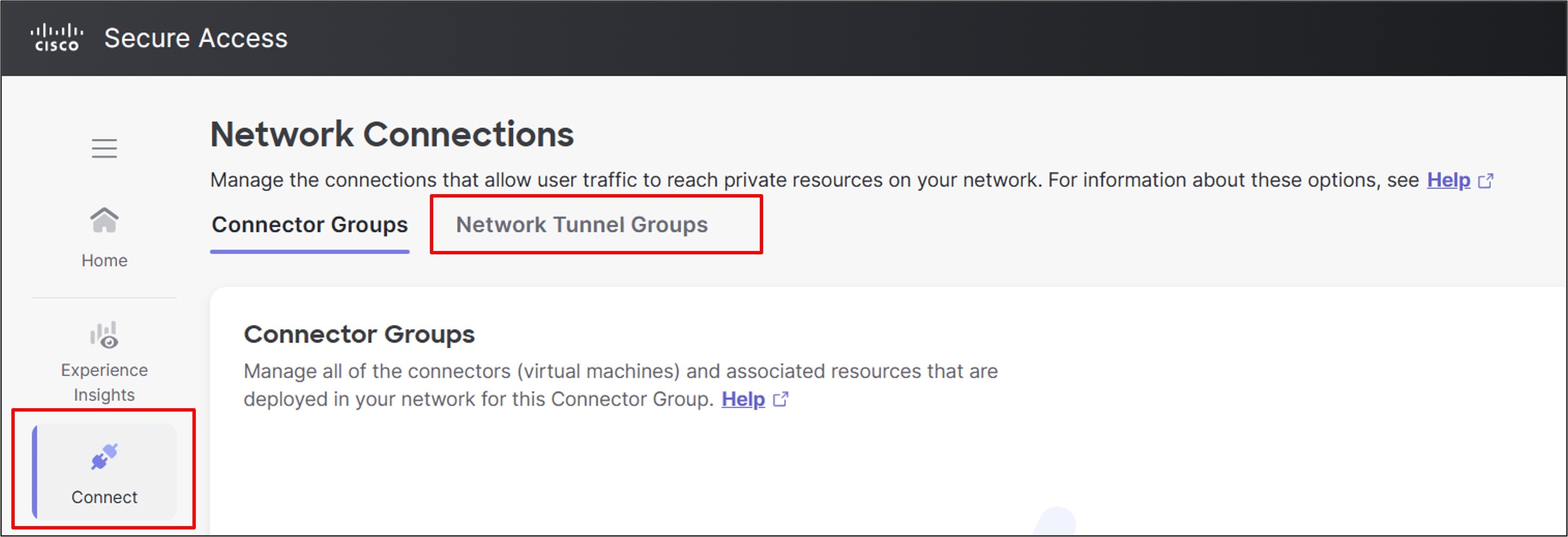
Step 3. Click + Add to add a new tunnel group.

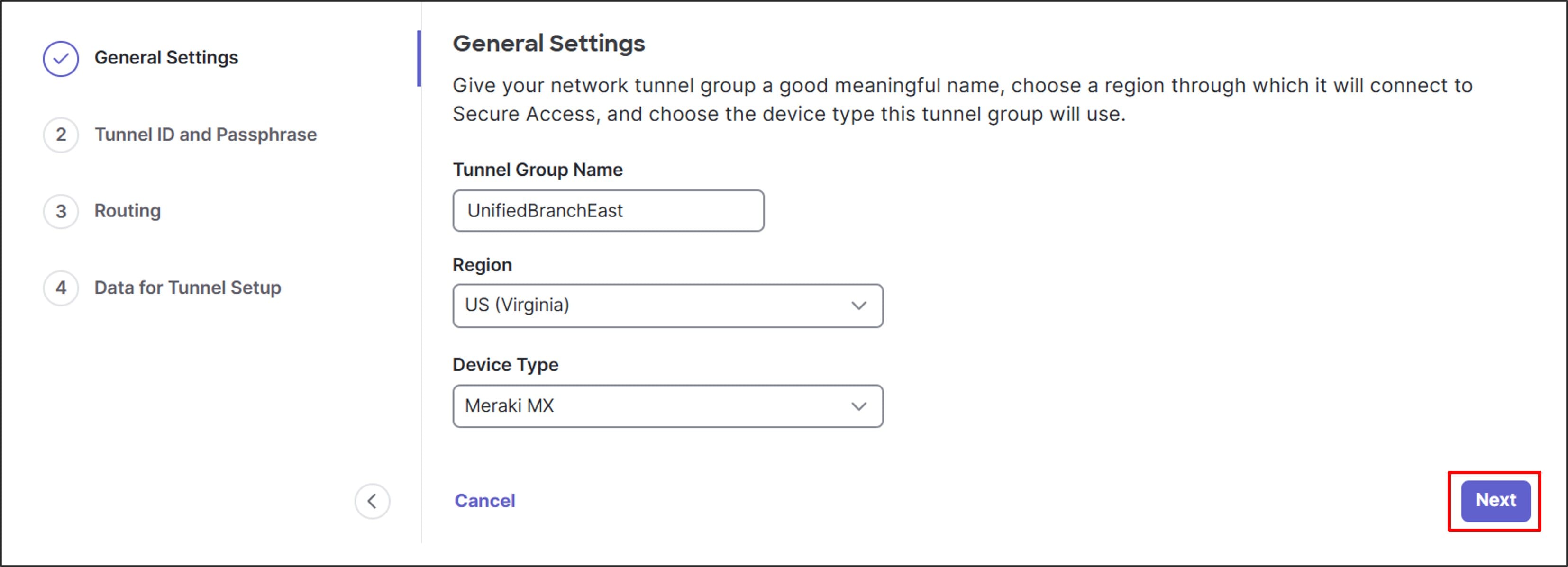
Step 4. Type in a meaningful Tunnel Group Name (UnifiedBranchEast), choose a Region (US (Virginia) in this example), and choose a Device Type (Meraki MX).
Step 5. Click Next.
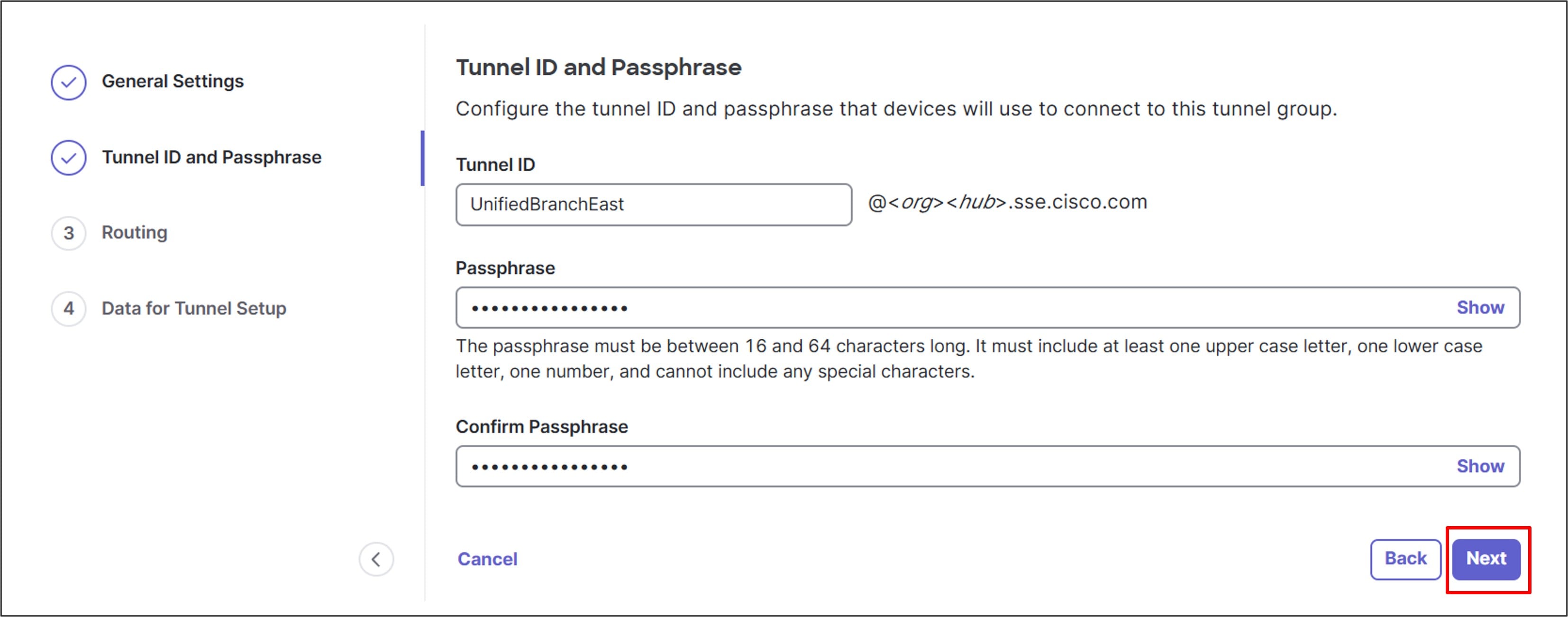
Step 6. Configure a Tunnel ID and Passphrase.
Step 7. Enter the passphrase again under Confirm Passphrase. The Tunnel ID is a unique identifier and paired with the pre-shared key, allows a tunnel on the router to authenticate to the Secure Access headend.
Step 8. Click Next.
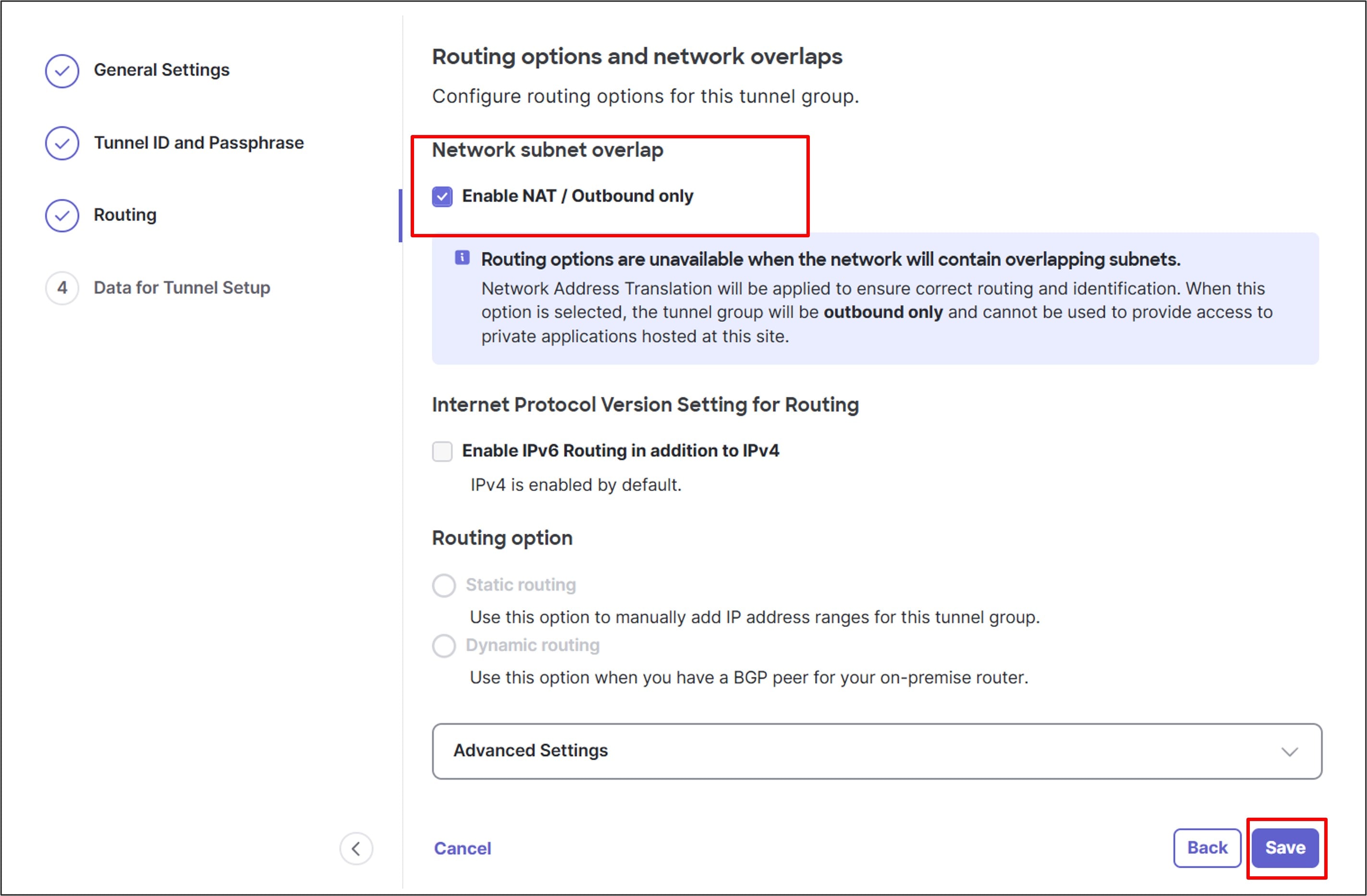
Step 9. Under Routing options and network overlaps > Network subnet overlap, select the Enable NAT / Outbound only option.
Step 10. Click Save.
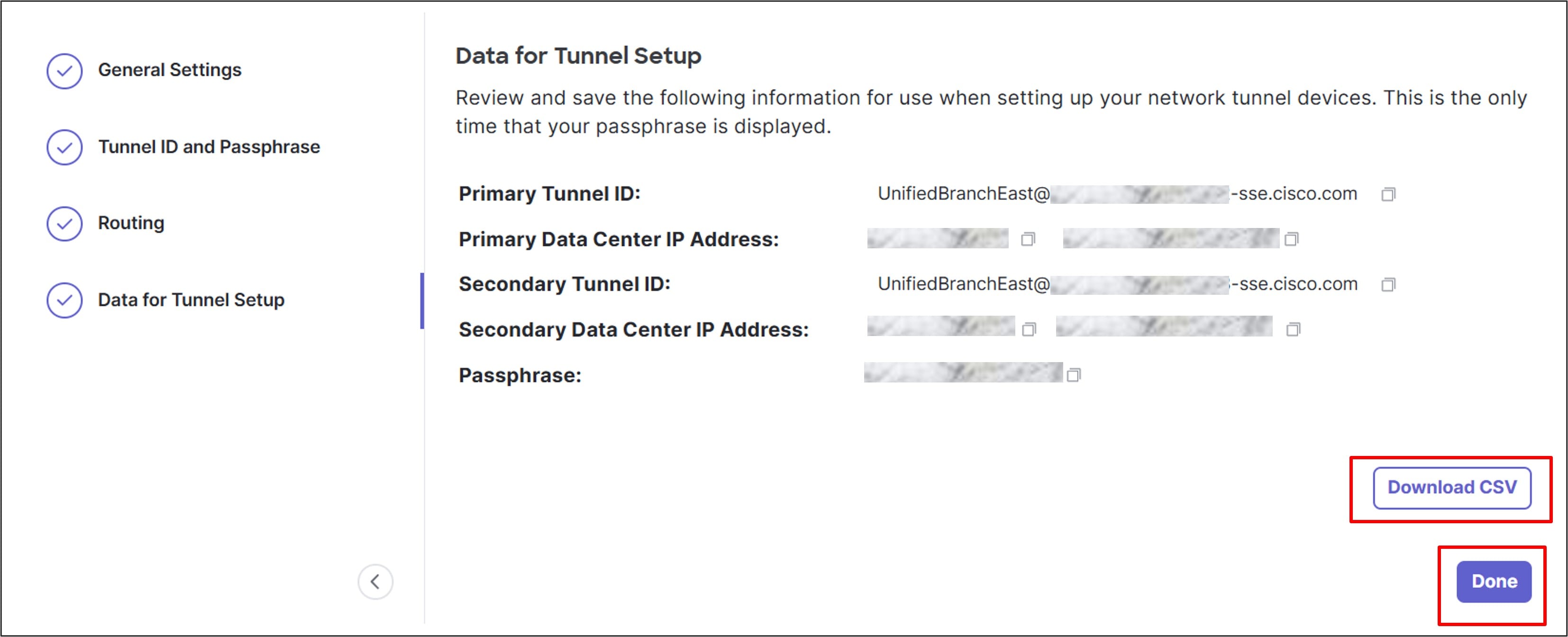
Step 11. On the Data for Tunnel Setup page, review the information.
Step 12. Click Download CSV to save the Tunnel ID and Data Center IP address information to use when setting up the tunnels on the network devices.
Step 13. Remember or copy the passphrase for safe keeping. It will not download in the CSV file, and it won’t be viewable in the tunnel setup information.
Step 14. Click Done.
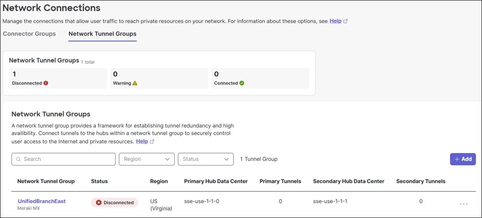
The status is shown for the tunnel, but it shows a disconnected status until the tunnels are established from the router.
MX router: Cisco Secure Access tunnel configuration
In this section, an active/standby tunnel pair is configured to connect Branch 2 to the Cisco Secure Access tunnel group that was configured in the previous section.
Procedure 29. To add the primary tunnel:
Step 1. Select a branch already configured with site-to-site VPN tunnels (RTP-Branch2).
Step 2. Navigate to Security & SD-WAN > Site-to-site VPN.
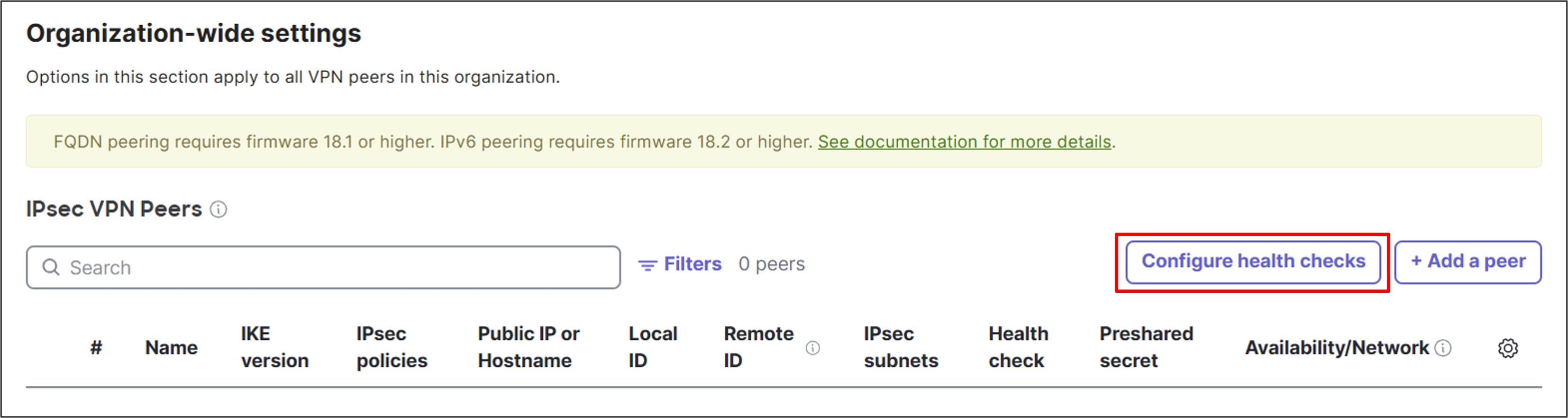
Step 3. Under Organization-wide settings > IPsec VPN Peers, click Configure health checks.
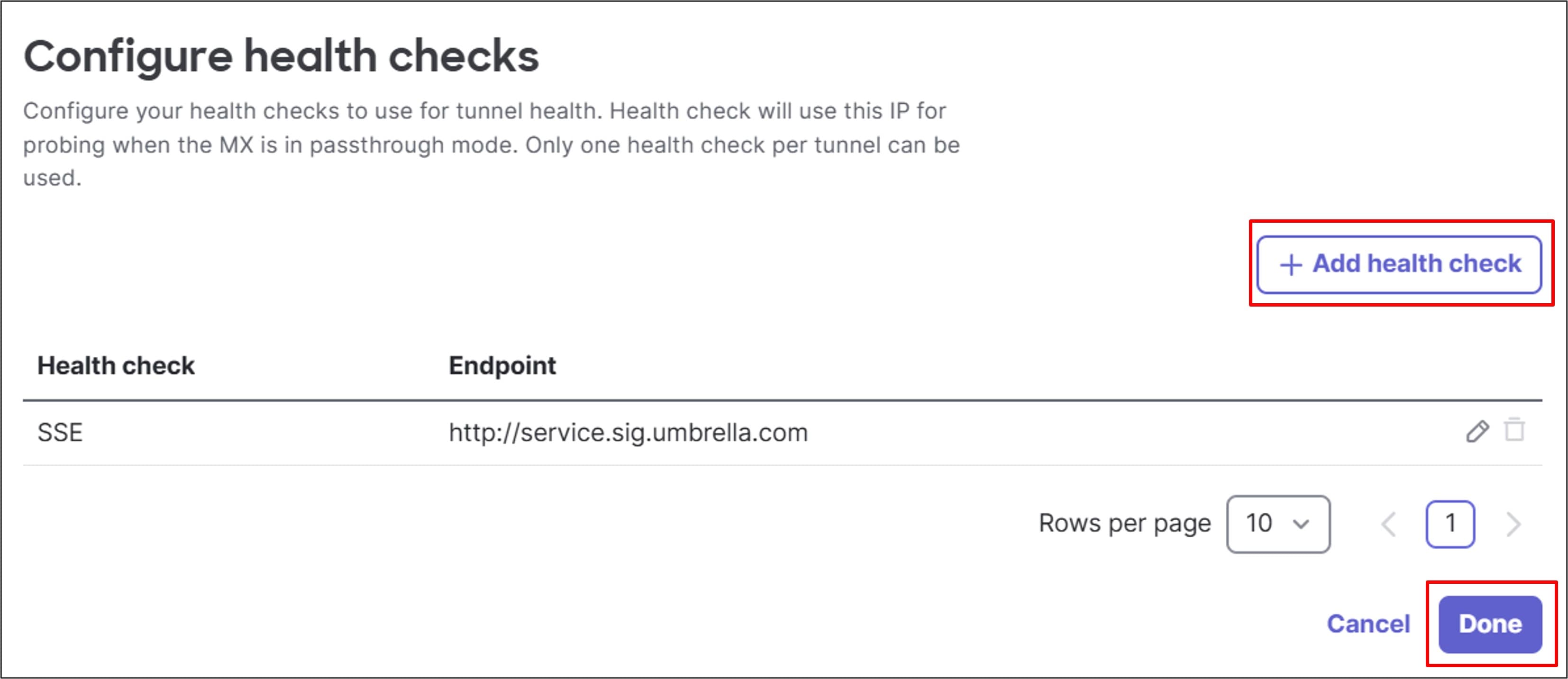
Step 4. Click + Add health check.
Step 5. Type the name for the Health check (SSE) and configure the Endpoint URL (http://service.sig.umbrella.com).
Step 6. Click Done.
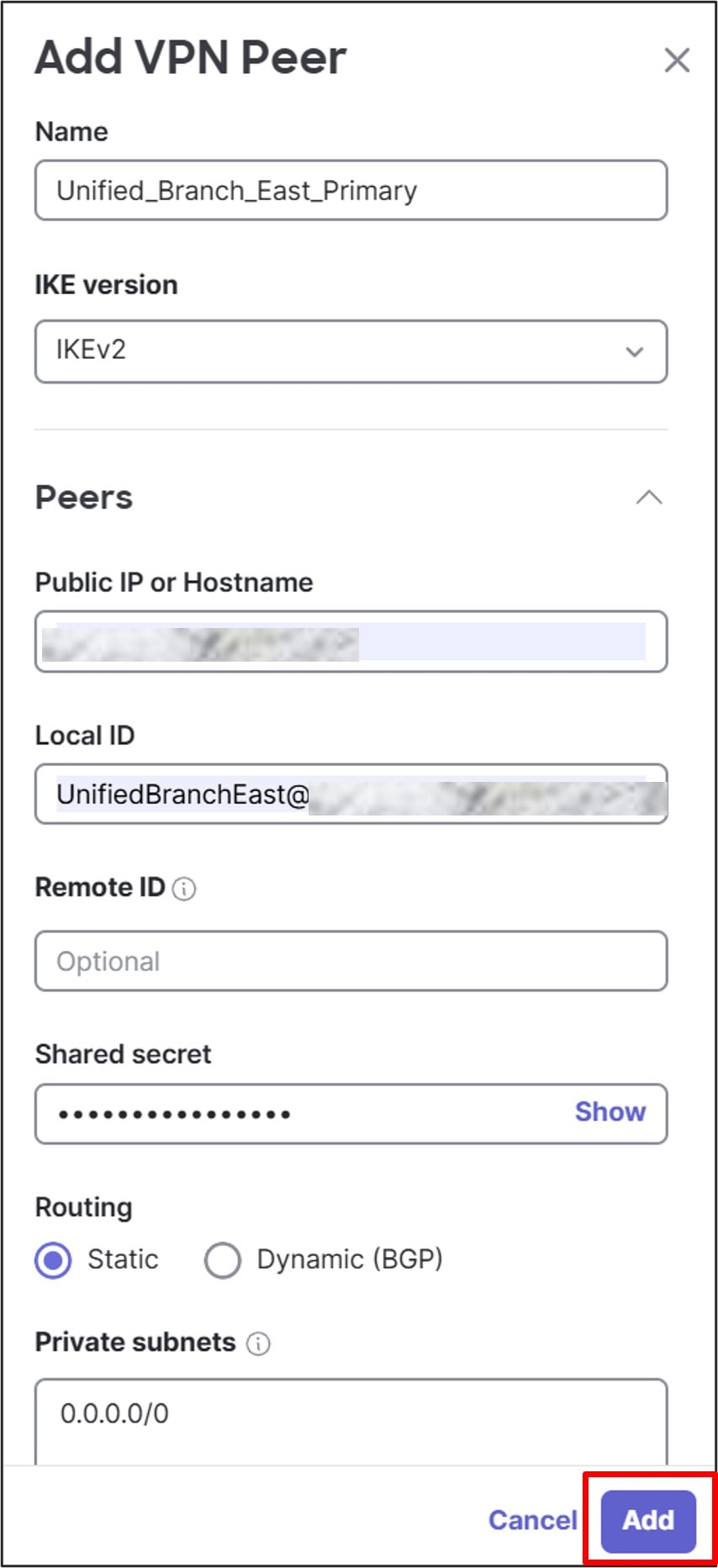
Step 7. Click + Add a peer and configure these settings for the Primary Tunnel:
● Name: Unified_Branch_East_Primary
● IKE version: IKEv2
● Peers
◦ Public IP or Hostname:
◦ Local ID:
◦ Shared Secret:
◦ Routing: Static
◦ Private subnets: 0.0.0.0/0
◦ Availability: SSE_East
● Multi-Uplink IPsec VPN: Enable
● Tunnel monitoring
◦ Health check: SSE
● IPsec policy
◦ Preset: Umbrella
Step 8. Click Add. Click Save or Save Changes.
Step 9. You may get a warning that VLAN subnets overlap with the default route that was just configured for SSE. IP traffic is routed to the smallest subnet/longest prefix that contains the IP address, and the SSE default route is used for traffic not matching anything else in the routing table. Click Confirm Changes.
Tech tip: Under IPsec Policy, the Umbrella Preset configures the following settings automatically:
Phase 1/Encryption: AES 256
Phase 1/Authentication: SHA1
Phase 1/Diffie-Hellman group: 14
Phase 1/Lifetime: 14400 sec
Phase 2/Encryption: AES 256
Phase 2/Authentication: SHA1
Phase 2/PFS group: Off
Phase 2/Lifetime: 3600 sec
Procedure 30. To add the secondary tunnel:
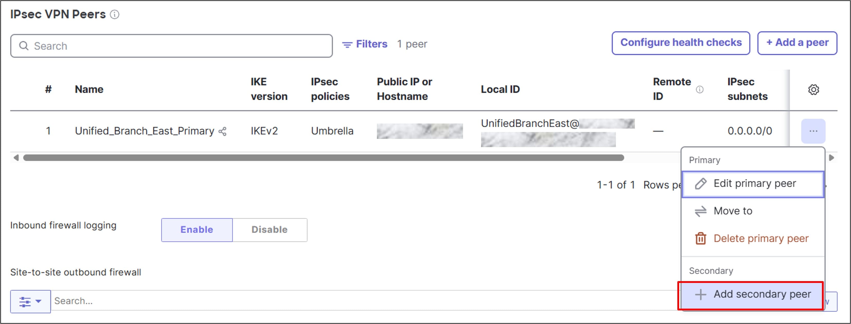
Step 1. To the far right of the defined tunnel, click … under the gear column.
Step 2. Select Add secondary peer.
Step 3. At the top of the form, click Inherit primary peer configurations to fill out most of the fields for the secondary peer.
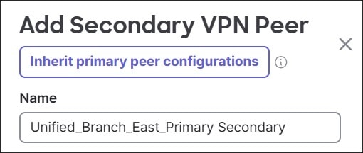
Step 4. Modify these fields:
● Name: Unified_Branch_East_Secondary
● Peers
◦ Public IP or Hostname:
◦ Local ID:
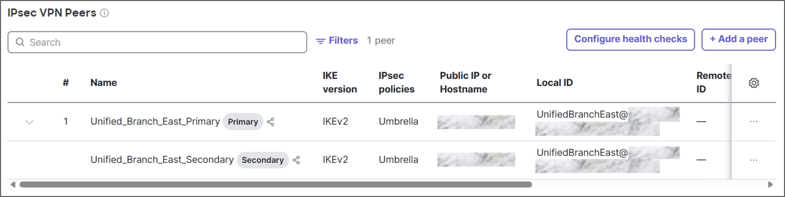
Step 5. Click Add. Click Save or Save Changes.
Step 6. You may get a warning that VLAN subnets overlap with the default route that was just configured for SSE. IP traffic is routed to the smallest subnet/longest prefix that contains the IP address, and the SSE default route is used for traffic not matching anything else in the routing table. Click Confirm Changes.
Validate status of Cisco Secure Access tunnels
Procedure 31. To check the status of the tunnels on Cisco Secure Access:
Step 1. Go to Connect > Network Connections and click the Network Tunnel Groups tab.
Step 2. Find the Network Tunnel Group created.
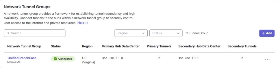
Step 3. Click … on the far right and choose View Details to see additional details about the connected tunnels.
Procedure 32. To check the status of the tunnels on the MX router:
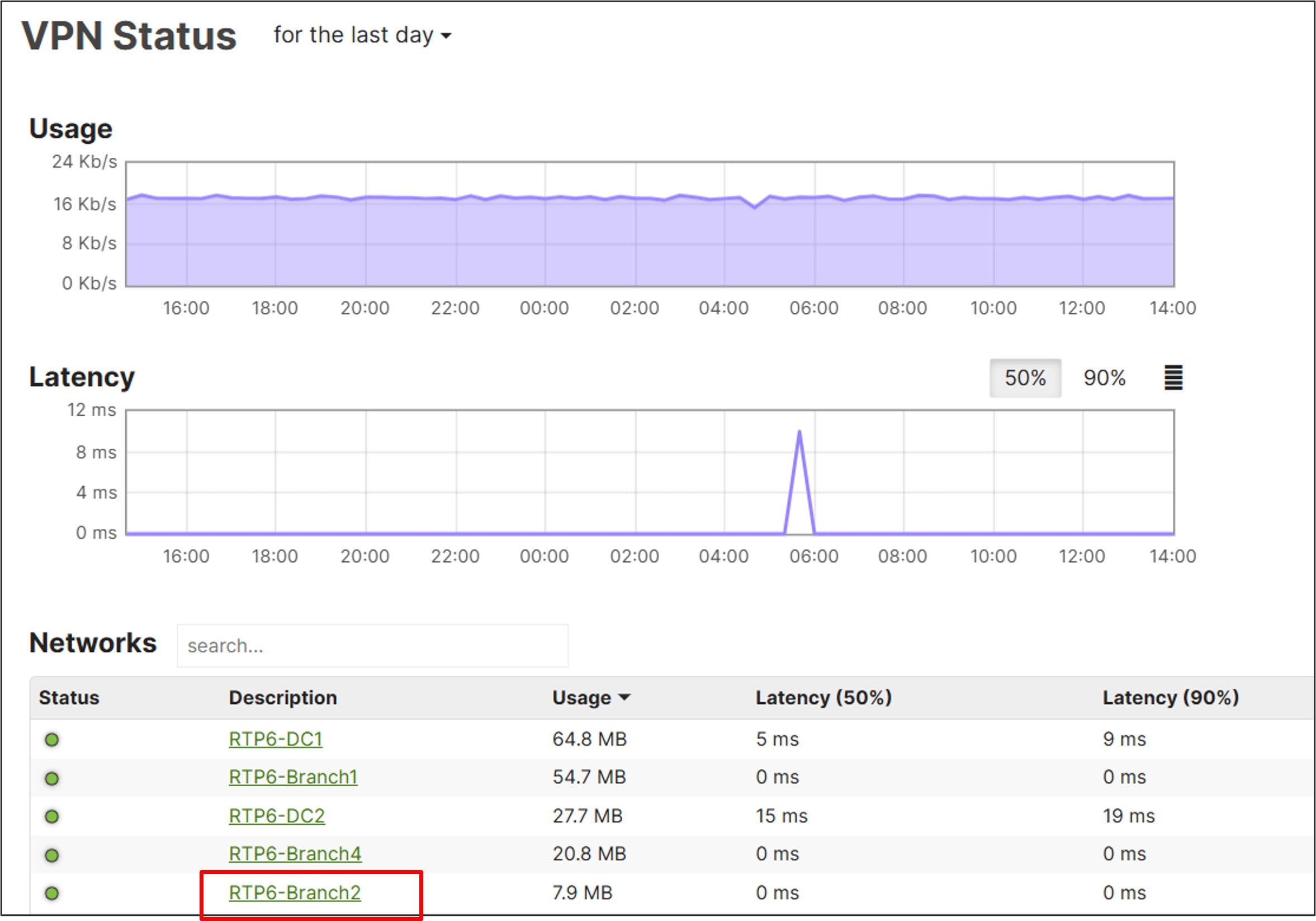
Step 1. Go to Organization > Monitor > VPN Status.
Step 2. Select the network to view (RTP6-Branch2).
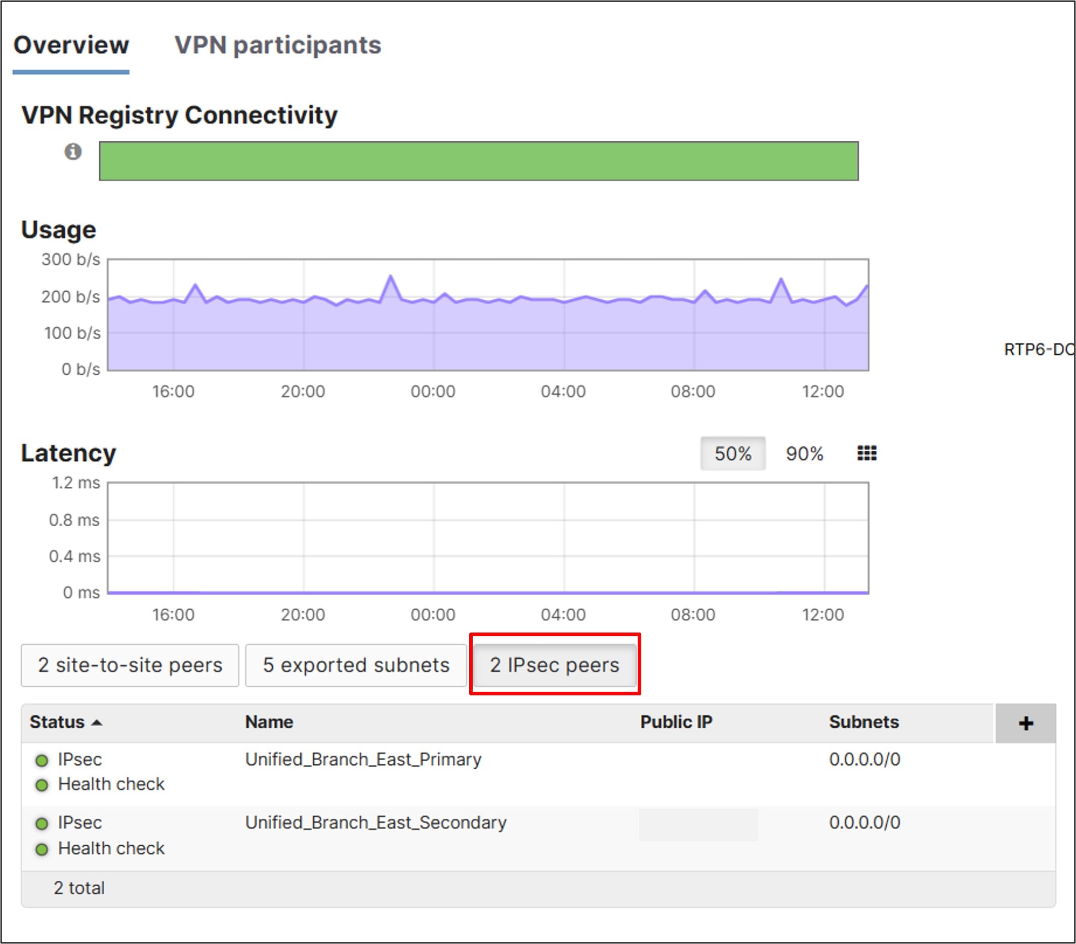
Step 3. Click the 2 IPsec peers box to view the status of the Cisco Secure Access peers.
MX router: Configure SD-WAN & traffic shaping
In this example, most Internet traffic takes the Cisco Secure Access tunnels. The primary tunnels load balance automatically by default as long as they are going to the same data center. Guest traffic, Data/Corporate SaaS traffic (O365 and Webex), device (switch and AP) dashboard INFRA traffic, and Default traffic (if any) take direct Internet access (DIA) from the branch.
Uplink configuration
In this example, rate limiting is set on each WAN link to match the provider’s service sub-line rate.
Procedure 33. To configure the WAN uplinks:
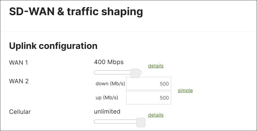
Step 1. Go to Security & SD-WAN > Configure > SD-WAN & Traffic Shaping.
Step 2. Under Uplink configuration, set WAN 1 to 400 Mbps and WAN 2 to 500 down (Mb/s) and 500 up (Mb/s) in this example.
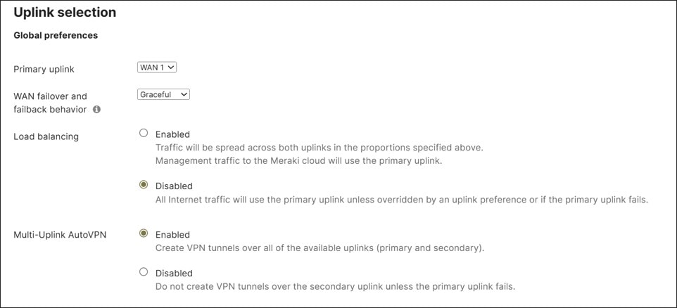
Step 3. Under Uplink selection>Global preferences, the Primary uplink is kept as WAN 1 (default), and Load balancing is disabled for direct Internet traffic. In addition, VPN tunnels are created over both available uplinks (Multi-Uplink AutoVPN is Enabled). Click Save or Save Changes.
Local internet breakout
Because default routes are pointing to the Cisco Secure Access tunnels, the site is assumed to be in full-tunnel mode. This means that all Internet traffic is sent through the Cisco Secure Access tunnels. The exception is GUEST and Default VLAN traffic because their VPN mode is set to disabled and Internet access for these VLANs is allowed as a rule in the L3 firewall. To break out traffic for DIA, VPN exclusions first need to be configured. In this example, SaaS application (Office 365 and Webex) traffic from the DATA VLAN need to be broken out, as well as dashboard INFRA VLAN traffic for the infrastructure device control planes.
Note: Traffic generated from the MX itself cannot be subjected to local Internet breakout rules, but traffic from infrastructure devices and other clients behind the MX can. MX-generated management traffic takes the default route in the table, which is through the Cisco Secure Access tunnels.
Procedure 34. To break out traffic for DIA:
Step 1. Go to Security & SD-WAN > Configure > SD-WAN & Traffic Shaping.
Step 2. Under Local internet breakout next to VPN exclusion rules, click Add +.
Step 3. Select Major applications and choose Office 365 Suite and Webex.
Step 4. Under Custom expressions, specify the Protocol, Destination and click Add, then specify the Dst port, and click Add expression.
Step 5. Use these custom expressions to allow dashboard cloud communication and VPN registry traffic for devices behind the MX router. Any is used for the protocol to cover TCP, UDP, and ICMP traffic. Any is used for the destination port to cover multiple ports.
Alternatively, multiple custom expressions can be configured so specific protocols and ports can be used. Refer to Upstream Firewall Rules for Cloud Connectivity for latest, up-to-date port requirements for the dashboard.
| Protocol |
Destination |
Dst port |
| UDP |
64.62.142.12/32 |
Any |
| ANY |
158.115.128.0/19 |
Any |
| ANY |
209.206.48.0/20 |
Any |
| ANY |
216.157.128.0/20 |
Any |
Step 6. Click Save or Save Changes.

SD-WAN policies: Internet
In this part of the configuration, traffic steering and performance-based routing policies are configured. The first section applies to Internet traffic only. Because no load-balancing is configured, traffic chooses the primary uplink (WAN 1 in this case) unless there is a policy to steer it differently. In this example, the following policies are preferred:
● Guest traffic is directed over WAN 1. If the link is declared down, the traffic is redirected to WAN 2.
● SaaS Traffic is directed over WAN 2 and should be redirected to WAN 1 if performance is poor.
● Device dashboard traffic is directed over WAN 2. If the link is declared down, the traffic is redirected to WAN 1.
Guest traffic doesn’t need to be included in the policy since this is the default behavior when no load-balancing is chosen and the primary uplink is WAN 1.
Note: Traffic generated from the MX itself is not subjected to policy. Policy applied to dashboard traffic affects the infrastructure devices behind the MX (switches and AP).
A custom performance class for SaaS traffic should be configured before configuring the policy.
Procedure 35. To configure a custom performance class for internet traffic:
Step 1. Go to Security & SD-WAN > Configure > SD-WAN & Traffic Shaping.
Step 2. Under SD-WAN policies > Custom performance classes, select Create a new custom performance class and enter these values:
● Name (SaaS_Traffic)
● Maximum latency (ms) (150)
● Maximum jitter (ms) (50)
● Maximum loss (%) (5).
Step 3. Click Save or Save Changes.

Step 4. When creating a policy that leverages the custom performance class just created, the newly created custom performance class may not show up as an option during policy configuration. To work around this, reload the web page after saving the custom performance class and before creating the policy.
Procedure 36. To configure routing policy for internet traffic:
Step 1. Go to SD-WAN Policies > Internet Traffic, click + Add policy, specify the Protocol, Source CIDR, Destination, and Uplink Selection.
Step 2. Click Save to add the policy to the dashboard.
Step 3. Repeat to add additional lines of policy.
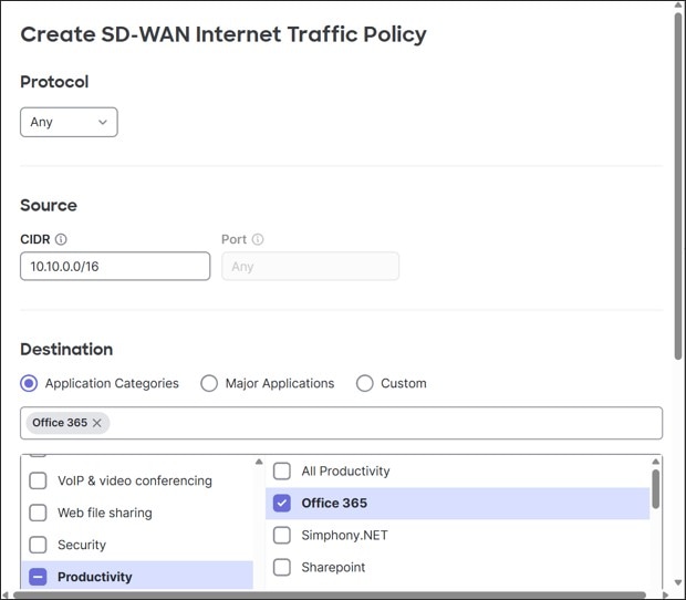
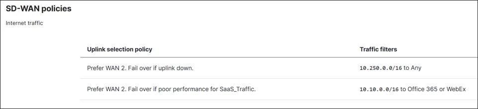
Step 4. Configure these two uplink selection policies for this example:
| Protocol |
Source CIDR |
Destination type |
Destination value |
Preferred uplink |
Fail over if: |
Performance class: |
| Any |
10.10.0.0/16 |
Application Categories |
Productivity>Office 365 VoIP & video conferencing>Webex |
WAN 2 |
Poor performance |
SaaS_Traffic |
| Any |
10.250.0.0/16 |
Custom |
CIDR=Any |
WAN 2 |
Uplink Down |
N/A |
Note: Dashboard destination traffic is Any. The VPN exclusions already defined what specific destination traffic is DIA (dashboard IP address destinations). If the previously configured performance class is missing from the drop-down, reload the web page and re-enter the policy.
Step 5. Click Save or Save Changes.
SD-WAN policies: VPN traffic
In this part of the configuration, traffic steering and performance-based routing policies are configured for VPN traffic. Load-balancing doesn’t apply to VPN traffic, so VPN traffic always chooses the primary link (WAN 1 in this case) unless there is a policy to steer it differently. In this example, the following policies are preferred:
● All VoIP and Video Conferencing traffic is directed over WAN 2 and should be redirected to WAN 1 if performance is poor.
● A critical company application (TCP from Any to 10.102.1.161/32:443) is directed over WAN 2 and should be redirected to WAN 1 if performance is poor.
● All other traffic is directed over WAN 1 and should be redirected to WAN 2 if performance is poor.
Custom performance classes for the critical application traffic and default traffic should be configured before configuring the policy.
Procedure 37. To configure custom performance classes for the critical application traffic:
Step 1. Go to Security & SD-WAN > Configure > SD-WAN & Traffic Shaping.
Step 2. From SD-WAN policies > Custom performance classes, select Create a new custom performance class then enter these parameters:
● Name (Critical_Apps)
● Maximum latency (ms) (150)
● Maximum jitter (ms) (20)
● Maximum loss (%) (2)
Step 3. Select Create a new custom performance class then enter these parameters:
● Name (Default_SLA)
● Maximum jitter (ms) (100)
● Maximum loss (%) (5)
Step 4. Click Save or Save Changes.

Procedure 38. To configure the routing policy for VPN traffic:
Step 1. Go to SD-WAN Policies > VPN traffic, click Add a preference.
Step 2. Under Traffic filters, click Add + then select an application or application family or create a custom expression to match VPN traffic.
Step 3. Select the preferred uplink then click Save.
Step 4. Repeat to add any additional lines of policy.
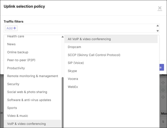
This example configures these three uplink selection policies:
| Traffic filters |
Preferred uplink |
Fail over if: |
Performance class: |
| VoIP & video conferencing>All VoIP & video conferencing |
WAN 2 |
Poor performance |
VoIP |
| Custom expressions>Protocol TCP from Source Any/Src port Any to Destination IP 10.102.1.161/32 Dst port 443 |
WAN 2 |
Poor performance |
Critical_Apps |
| Custom expressions>Protocol Any from Source Any Src port Any to Destination Any Dst port Any |
WAN 1 |
Poor performance |
Default_SLA |
Step 5. Click Save or Save Changes.

Traffic Shaping rules
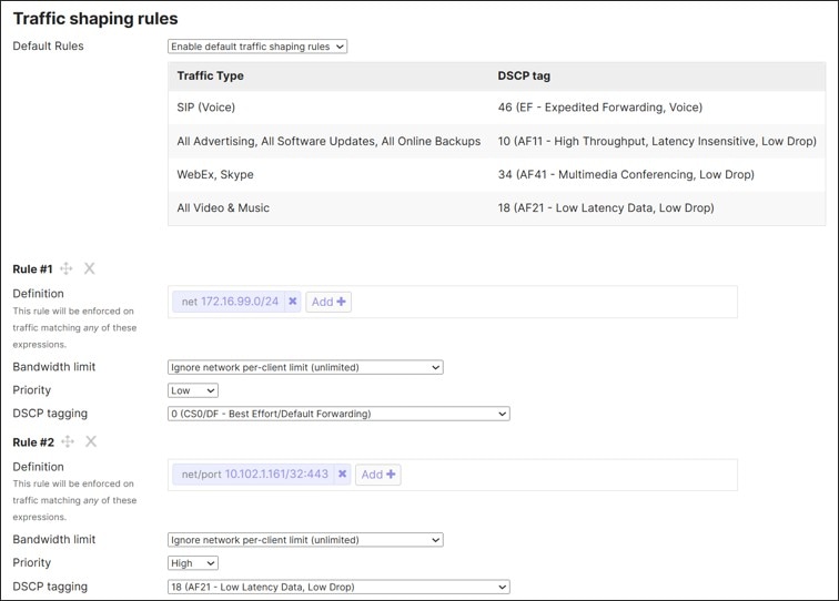
In this example, the default traffic shaping rules are kept and only two additional rules are added. The two rules are to give lower priority to guest traffic and give higher priority to the critical application traffic that was referenced in SD-WAN policies > VPN traffic.
Procedure 39. To configure traffic shaping rules:
Step 1. Under Security & SD-WAN > Configure > SD-WAN & Traffic Shaping > Traffic shaping rules, next to Default Rules, ensure that Enable default traffic shaping rules is selected.
Step 2. Click Create a new rule.
Step 3. Specify these values:
● which traffic should be matched?
● what bandwidth limit should be applied, if any?
● what is the designated priority for this traffic?
● are there any DSCP tagging requirements?
This is the configuration for this example:
| Rule # |
Definition |
Bandwidth limit |
Priority |
DSCP tagging |
| 1 |
Custom expressions>172.16.99.0/24 (guest) |
Ignore network per-client limit (unlimited) |
Low |
0 (CS0/DF – Best Effort/Default Forwarding) |
| 2 |
Custom expressions>10.102.1.161/32:443 |
Ignore network per-client limit (unlimited) |
High |
18 (AF21 – Low Latency Data, Low Drop) |
Step 4. Click Save Changes.
MX router: Configure threat protection
Procedure 40. To configure threat protection:
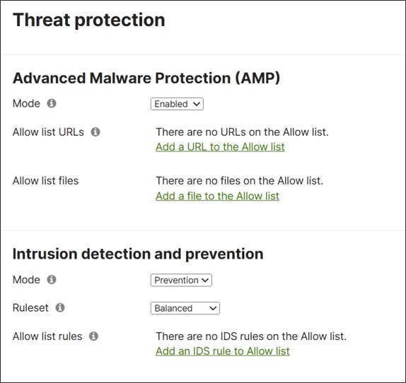
Step 1. Under the Security & SD-WAN > Configure > Threat Protection page, Advanced Malware Protection (AMP) and Intrusion detection and prevention can be configured.
Step 2. Under Advanced Malware Protection (AMP), ensure the Mode is set to Enabled.
Step 3. Under Intrusion detection and prevention, set the Mode to Prevention and select Balanced next to Ruleset.
Step 4. Click Save or Save Changes.
MX router: Configure content filtering
Procedure 41. To configure content filtering:
Step 1. Go to Security & SD-WAN > Configure > Content Filtering.
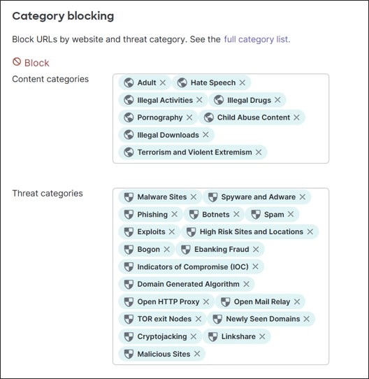
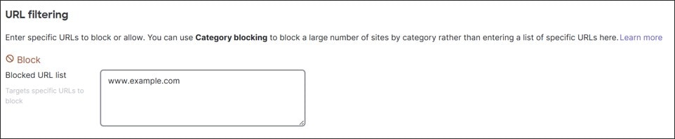
Step 2. Under Category blocking, select what content and threat categories should be blocked, as well as any URLs that should be allowed or blocked under URL filtering.
Configuration for this example:
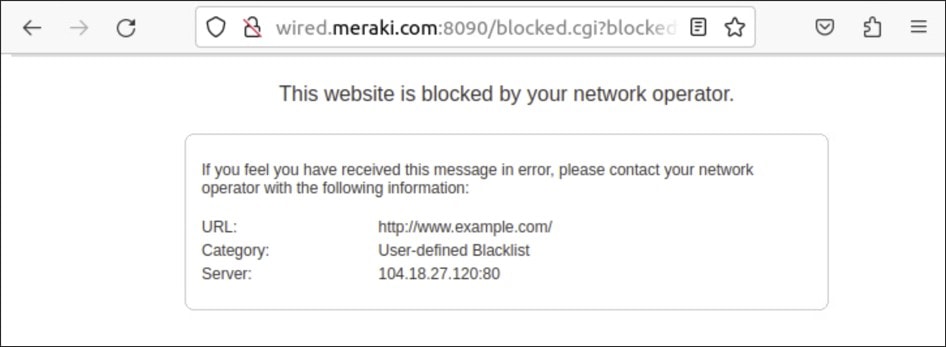
www.example.com is included in the URL filtering blocked URL list>
Step 3. Click Save.
Modify INFRA device management
Now that the MX router and switch ports to the transports have been configured, the infrastructure devices (switches and AP) can be moved into VLAN 999. Ensure that centralized DNS is available before putting the devices into the INFRA VLAN 999.
Switch: Configure trunk to AP with Native VLAN 999
The AP is moved into VLAN 999 by modifying the native VLAN of the trunk port connected to it.
Procedure 42. To configure a trunk to the AP with native VLAN 999:
Step 1. Go to Switching > Monitor > Switch Ports.
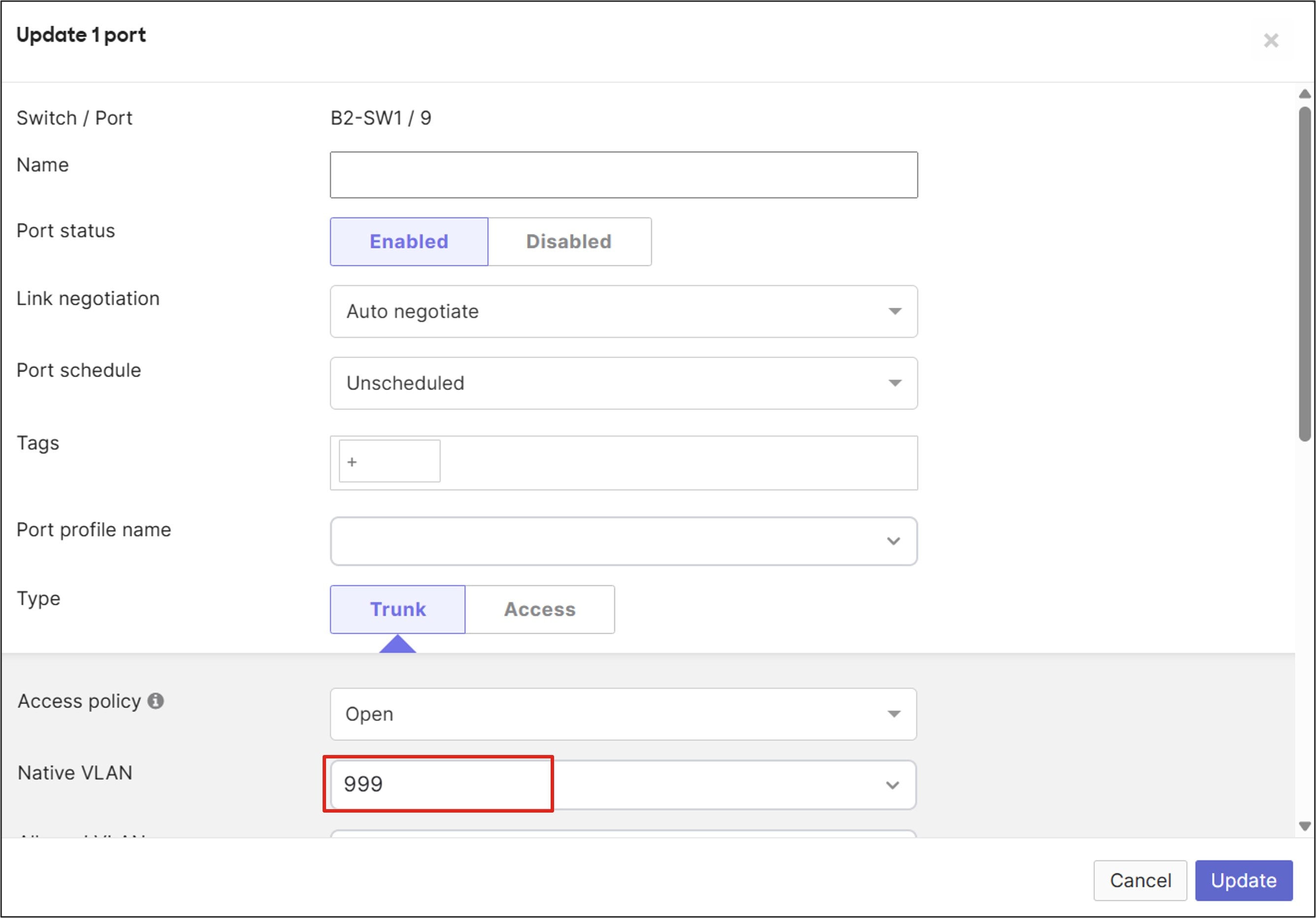
Step 2. Click the switch port to the AP (B2-SW1/9) to edit the settings.
Step 3. Next to Native VLAN, type 999, then click Update.
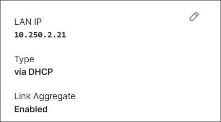
Step 4. When configured, go to Wireless > Monitor > Access Points, and select the AP to validate the changes.
It could take a few minutes for the IP changes to take place. The new IP address is the one that was reserved configuring DHCP pools for the INFRA VLAN on the MX router.
Switch: Configure switch management VLAN
For all switches and switch stacks, switch management traffic is tagged with VLAN 999.
Procedure 43. To set the switch management VLAN:
Step 1. Go to Switching > Configure > Switch Settings and under VLAN configuration > Management VLAN, configure 999.
Step 2. Click Save changes. This sets the management VLAN for all switches in the network.
The local switch setting overrides this setting.
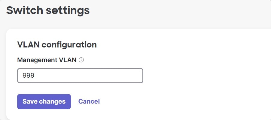
Step 3. When configured, go to Switching > Monitor > Switches, select a switch to validate the changes. It could take a few minutes for the IP changes to take place. The new IP address is one that was reserved configuring DHCP pools for the INFRA VLAN on the MX router.
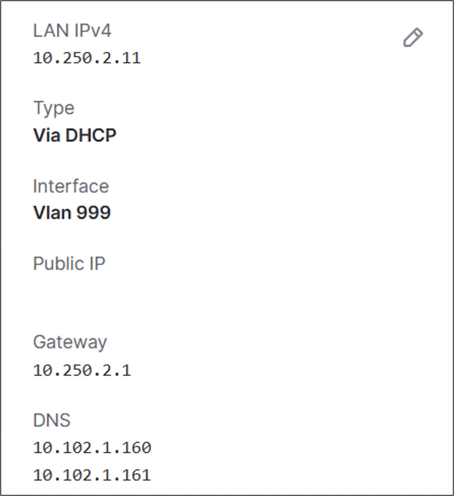
Tech tip: For some MS switch stack models (such as the MS150, but not the MS390), there may be an issue moving all switch members into VLAN 999. Some members may switch to VLAN 999, and others may stay in VLAN 1. If any switch stays in VLAN 1, there will be no reachability to centralized services (such as RADIUS) in the data center for that switch. If this issue occurs, instead of modifying the switch settings, configure the native VLAN 999 on the trunk of the MX router (go to Security & SD-WAN > Configure > Addressing & VLANs, Edit the trunk ports connected to the switch stack, and configure the Native VLAN as 999). This may generate a VLAN mismatch error on the switch, but the switch should be able to obtain an IP address and have reachability in VLAN 999 using the workaround. Any devices that are onboarded afterwards should obtain an IP address in VLAN 999 instead of VLAN 1. If this workaround is implemented, any switch trunk to an Access Point must be configured for Native VLAN 1 (and not VLAN 999).
Switch: Configure switch settings
Spanning tree root
The switch is configured to be the root of spanning tree.
Procedure 44. To configure spanning-tree settings:
Step 1. Go to Switching > Configure > Switch Settings under STP configuration.
Step 2. Click Set the bridge priority for another switch or stack.
Step 3. A window may pop up warning that changing the STP bridge priority may cause a short disruption on all switches in the network as spanning tree is re-calculated. Click Got it.
Step 4. Click the text box under Default.
Step 5. From the drop-down menu Switches/Stacks name (B2-SW-STACK1) and under Bridge priority, from the drop-down menu, select 4096.
Step 6. Click Confirm.
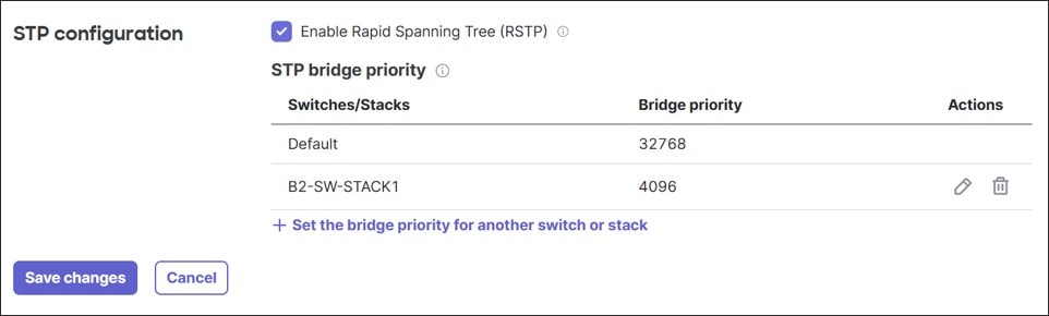
Step 7. Click Save changes.
Quality of Service (QoS)
In this example, minimal Quality of Service configurations are made. Under Switching > Configure > Switch Settings > Quality of service, default DSCP-to-CoS mappings are retained. Guest traffic (VLAN 50) is untrusted with all traffic set to 0 (default), while incoming DSCP is trusted for Data (VLAN 10), Voice (VLAN 20), IOT (VLAN 30), and PCI traffic (VLAN 40).
Procedure 45. To configure QoS:
Step 1. Click + Add a QoS Rule for this network.
Step 2. Fill in VLAN, Protocol (ANY), and whether to Trust incoming DSCP.
Step 3. If DSCP is not trusted, set DSCP to a value.
Step 4. Click Save.
Step 5. Repeat until all VLANs are entered.
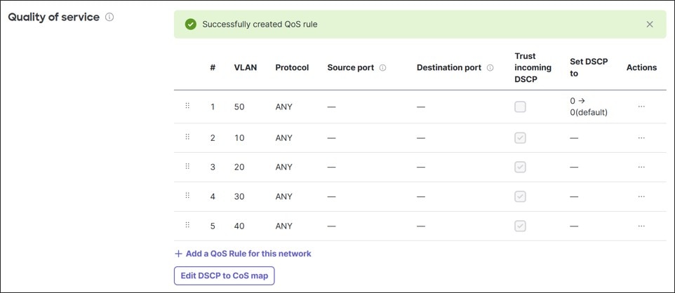
Storm control
In this example, storm control is configured on the wired access ports.
Procedure 46. To configure storm control:
Step 1. Go to Switching > Configure > Switch Settings and under Storm control, click + Set the port bandwidth for another traffic type.
Step 2. Enter the Traffic type and % of available port bandwidth.
Step 3. Click Confirm.
Step 4. Repeat to finish the traffic types.
Step 5. When finished, click Save changes.
Tech tip: While percentages for what is normal traffic varies for each network, in this example, multicast traffic is set to 30%, broadcast traffic is set to 20%, and unknown unicast is set to 10%. It is important to understand the network applications and to monitor interface statistics for broadcast/multicast traffic to determine what is normal for the network. Ensure the percentages allow normal network traffic to flow correctly, especially before applying the settings to uplink and AP ports.
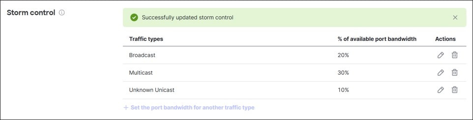
Switch: Configure access policies
Procedure 47. To configure 802.1x on the switch:
Step 1. In this example, go to Switching > Configure > Access Policies.
Step 2. Click + Add policy.
Step 3. Configure a Name (RADIUS-MAB) and Authentication method (RADIUS server).
Step 4. Check the check boxes for RADIUS Server testing, RADIUS CoA support, and Enable RADIUS accounting servers.
Step 5. Click + Add a server and enter the Host, Secret, and Port number for RADIUS Auth and Accounting.
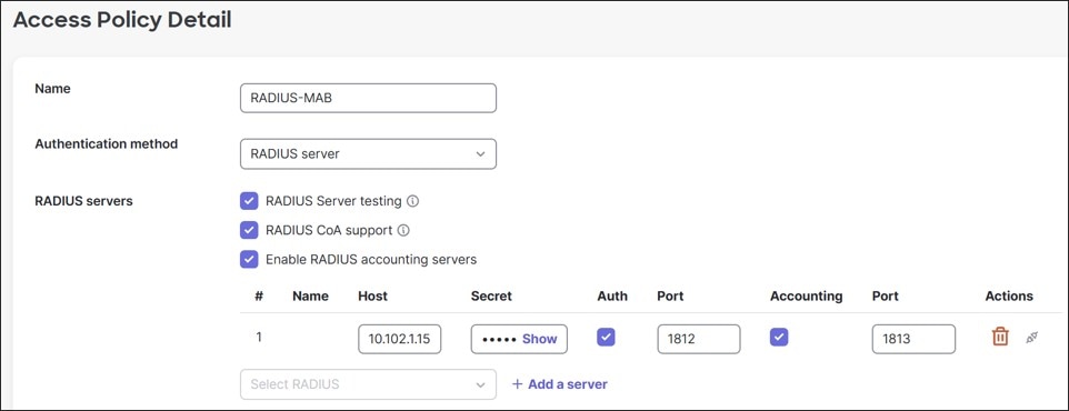
Step 6. Next to Connection under Policy Type, select Hybrid authentication since both 802.1x and Mac Authentication Bypass can be used. Host mode is set to Multi-Auth and 802.1x control direction defaults to Both.
Step 7. Next to Options, select Voice auth.
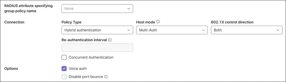
Step 8. Click Save.
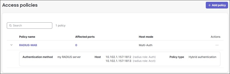
Switch: Configure ports
In this example, the following port configurations are completed. Ports 3-5 (transport ports) on each switch have already been configured, and others have been partially configured.
Ports 1-2 (SW1/SW2): Uplink ports to the routers
Port 9 (SW1): Link to the access point (AP)
Ports 6-8 (SW1/SW2): Unused Infrastructure (shutdown)
Ports 10-12 (SW1): Unused AP ports (shutdown)
Ports 9-12 (SW2): Unused AP ports (shutdown)
Ports 13-28 (SW1/SW2): Wired client ports
Ports 1-2: Uplink ports
Procedure 48. To configure an uplink port:
Step 1. Go to Switching > Monitor > Switch Ports. Ports 1 and 2 on each switch are the uplinks to the MX routers in our example and will retain most of the default settings.
Step 2. The Name and Allowed VLANs are already configured in a previous section. Check the check boxes to the far left of Switch / Port B2-SW1/1, B2-SW1/2, B2-SW2/1, and B2-SW2/2 and click Edit.
Note: The Storm control option appears when the storm control settings are configured. It is important to not set the storm control settings too low before applying them to ports as legitimate traffic can be dropped.
Step 3. Verify these setting configurations:
● Name: Uplink to Router
● Port Status: Enabled
● Link negotiation: Auto negotiate
● Port schedule: Unscheduled
● Type: Trunk
◦ Access policy: Open
◦ Native VLAN: 1
◦ Allowed VLANs: 1,10,20,30,40,50,999
● STP guard: Disabled
● Port isolation: Disabled
● Trusted DAI: Disabled
● UDLD: Alert only
● PoE: Enabled
● Storm control: Enabled
Step 4. Click Update.
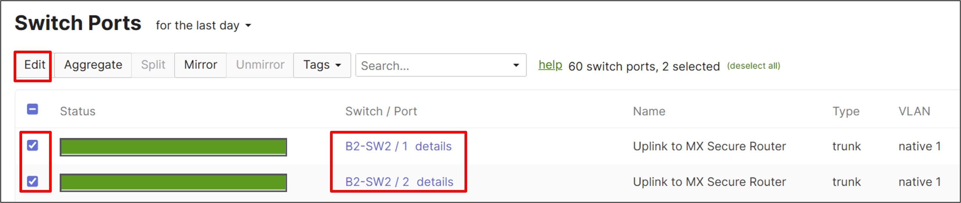
Port 9: Access Point (AP) port
In this example, Port 9 on B2-SW1 is connected to the access point. By default, the port is configured as a trunk carrying all VLANs.
Note: The native VLAN was originally 1 but now set to VLAN 999 in a previous step in order to put the AP management traffic into VLAN 999.
RSTP is also already enabled, UDLD is set to Alert only, PoE is enabled, and Storm control is enabled because it is enabled by default when storm control settings have been configured under Switching > Monitor > Switch settings.
Procedure 49. To configure the link to the AP:
Step 1. Click Switch / Port B2-SW1/9.
Step 2. Configure these settings:
● Name: Link to AP
● Allowed VLANs: 1,10,20,30,40,50,999
● STP Guard: BPDU guard
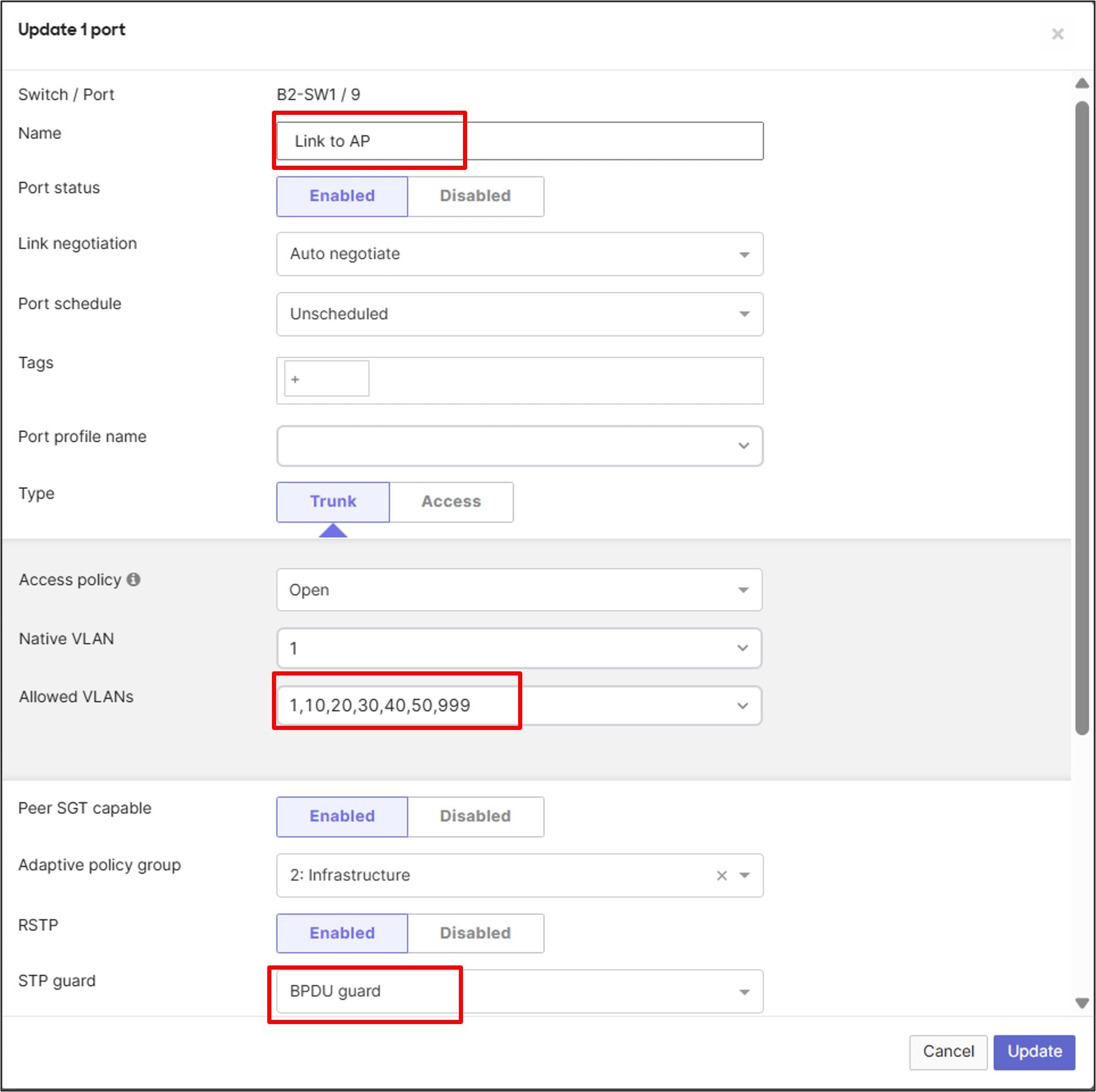
Step 3. Click Update.
Ports 6-12: Unused Infrastructure/AP ports
Unused ports 6-8 and 10-12 on both switches are disabled, and port 9 is also disabled on B2-SW2.
Procedure 50. To configure unused infrastructure and AP ports:
Step 1. Check the check box to the left of each port and click Edit at the top of the screen.
Step 2. Next to Name, type Disabled.
Step 3. Next to Port status, click Disabled.
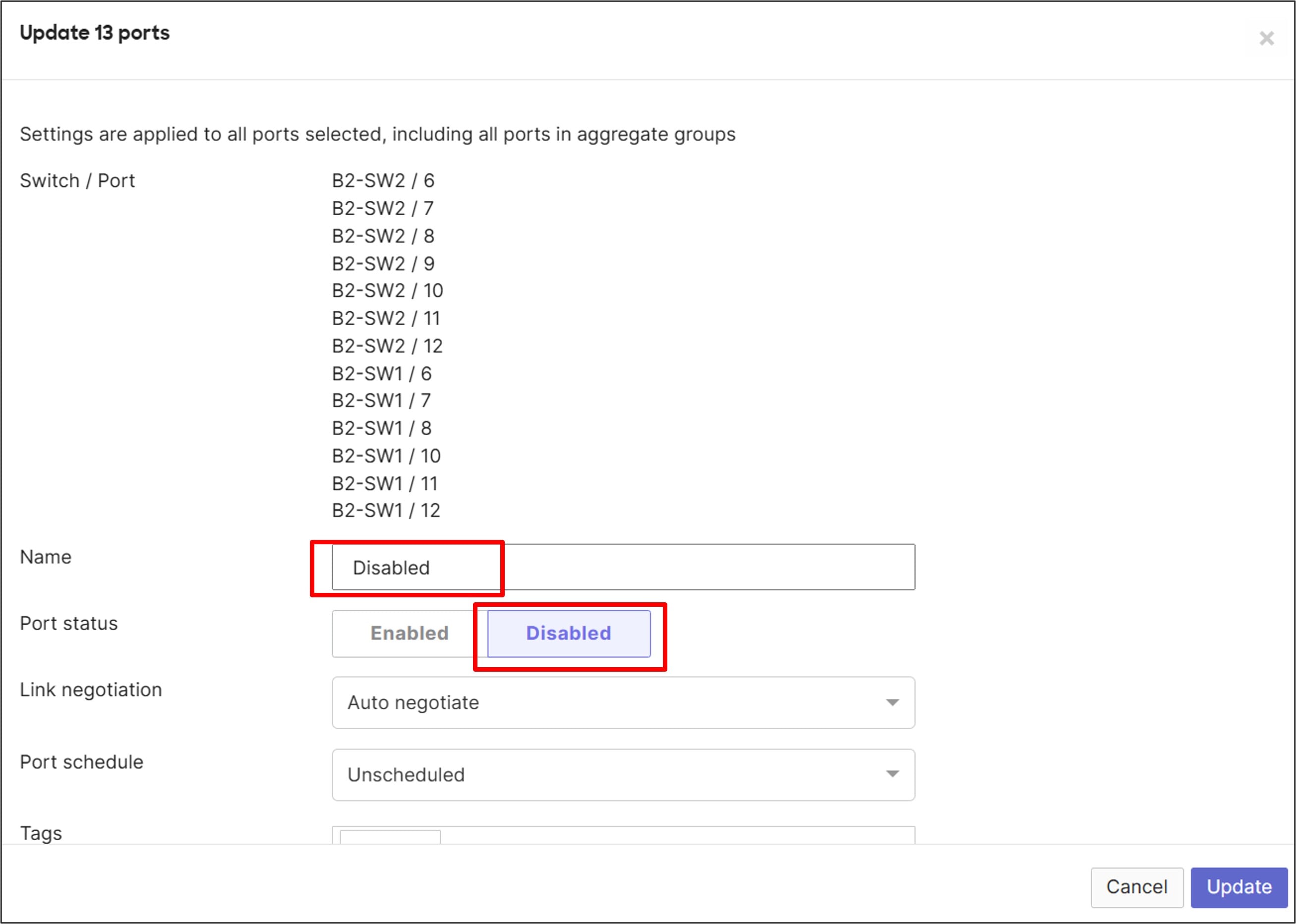
Step 4. Click Update.
Ports 13-28: Wired client ports
Procedure 51. To configure wired client ports:
Step 1. For the rest of the ports (ports 13-28), on both switches, check the check box to the left of each port and click Edit at the top of the screen.
Clicking a box, then holding the shift key and clicking a box further down the list selects a range.
Note: RSTP and Storm control are already enabled, and UDLD is set to Alert only.
Step 2. Configure these settings:
● Name: Access Port
● Type: Access
● Access policy: RADIUS-MAB
● VLAN: 10
● Voice VLAN: 20
● STP Guard: BPDU Guard
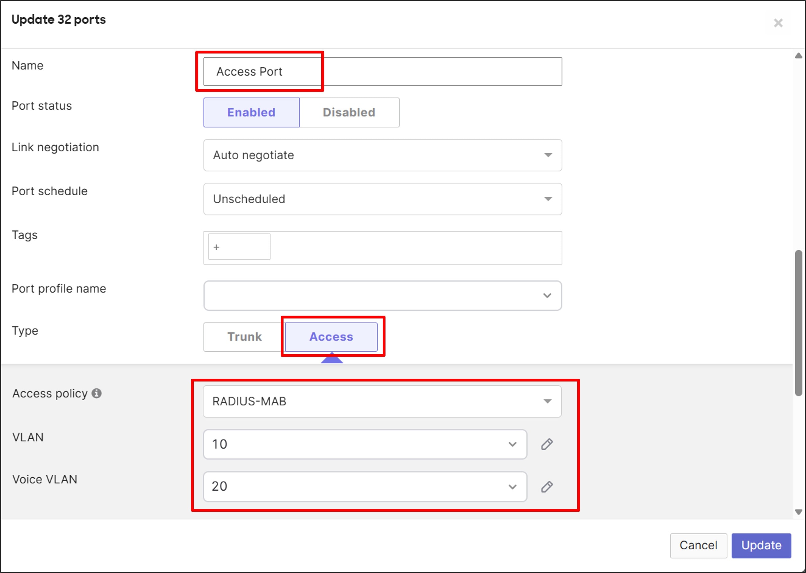
Step 3. Click Update.
Wireless Access Point: Configure Guest SSID
Access control
Procedure 52. To configure Guest wireless access control:
Step 1. Go to Wireless > Configure > Access Control.
Step 2. From the drop-down menu, select an unconfigured SSID (SSID 1, labeled RTP6-Branch2 – wireless Wi-Fi).
Step 3. Provide an SSID name (in this example BR2-GuestWiFi), and next to SSID status, select Enabled. The SSID will not be hidden.
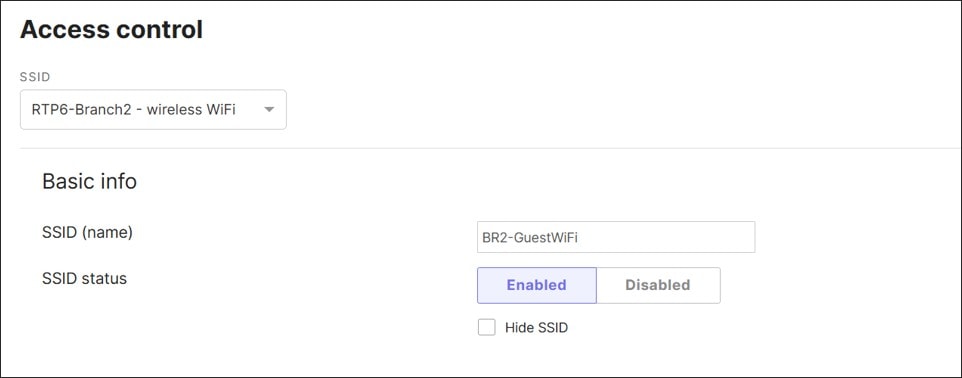
Step 4. Select Security (Open (no encryption)), enable Mandatory DHCP, and under Splash page, select Click-through – this requires guests to view and acknowledge a splash page before being allowed on the network.
Step 5. Under Client IP and VLAN, select External DHCP server assigned and leave the setting in Bridged mode.
Step 6. Next to VLAN tagging, from the drop-down menu, select the VLAN ID field and enter 50. This value represents the pre-configured Guest VLAN, which is already enabled on the trunk connecting the AP/switch to the MX router.
Step 7. Click Save.
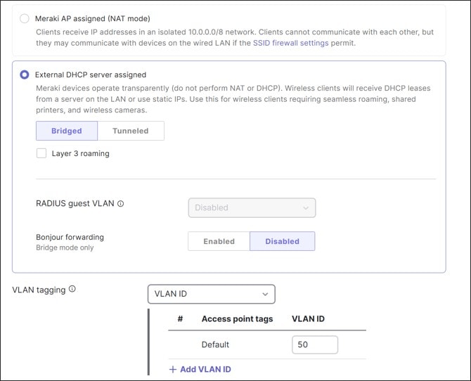
Step 8. On this same page, scroll up above the RADIUS section and click Splash page settings.
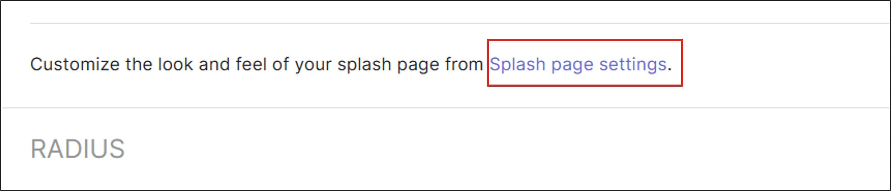
Step 9. Under the Splash page, select the guest SSID (BR2-GuestWiFi).
Step 10. Under Official themes, ensure Modern is selected.
Step 11. Under Customize your page next to Welcome message, type “Click to continue if you agree to the terms of usage of this guest service.”
Step 12. Click Save or Save Changes.
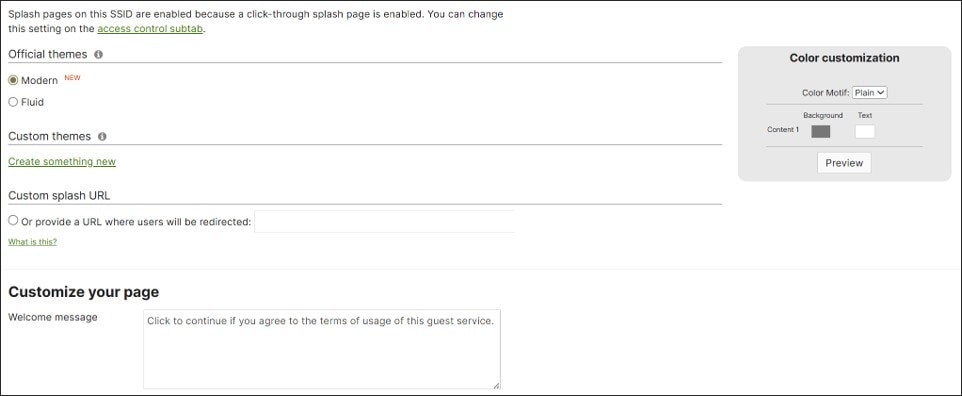
Firewall and traffic shaping
Procedure 53. To configure Guest wireless firewall and traffic shaping:
Step 1. Under Wireless > Firewall & Traffic Shaping, select the guest SSID from the drop-down menu (BR2-GuestWiFi).
Step 2. Under Block IPs and ports next to Layer 2 LAN isolation, select Enabled.

Step 3. Under Outbound rules, ensure that Deny is selected for “IPv4 Any Local LAN Any” for the Wireless clients accessing LAN rule.
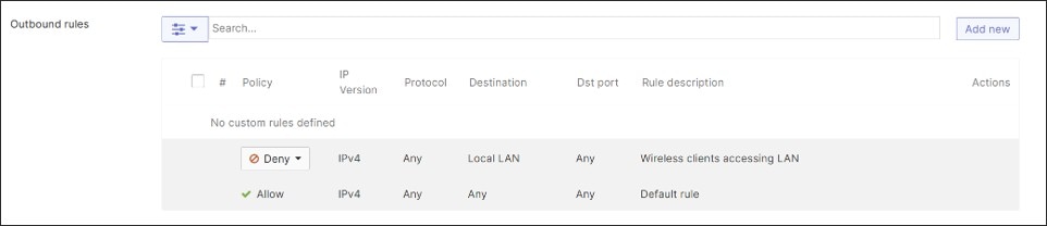
Step 4. For this example, under Traffic shaping rules, set the Per-client bandwidth limit to 50 Mbps and Enable SpeedBurst.
Step 5. Set the Per-SSID bandwidth limit to 100 Mbps.
Step 6. Next to Shape traffic, select Shape traffic on this SSID and next to Default Rules, verify that Enable default traffic shaping rules is selected.
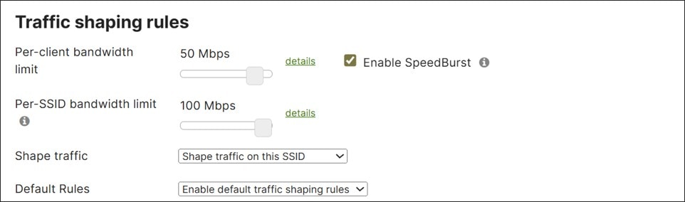
Step 7. Click Save Changes.
Network-Wide: Configure group policy
In this example, group policy is applied after RADIUS authentication occurs in the Corp wireless SSID. The RADIUS server passes back a filter-ID parameter, which corresponds to a group policy name and is applied to the wireless user accessing the network. In this example, there are 4 policy groups: DATA, VOICE, IOT, and PCI. The policy groups assign a VLAN but do not assign an SGT in this example. The SGT is assigned through a separate RADIUS attribute. If SGTs were assigned, more policies would need to be created to cover different user groups under the DATA VLAN.
Procedure 54. To configure group policy for Corp wireless:
Step 1. Go to Network-wide > Group Policies and click Add a group.
Step 2. Next to Name, type DATA, and next to Adaptive Policy SGT, select Do not assign SGT.
Step 3. Under Wireless only, next to VLAN, from the drop-down menu, select Tag VLAN and type 10 in the box.
Step 4. Click Save Changes.
Step 5. Repeat for VOICE (VLAN 20), IOT (VLAN 30), and PCI (VLAN 40).
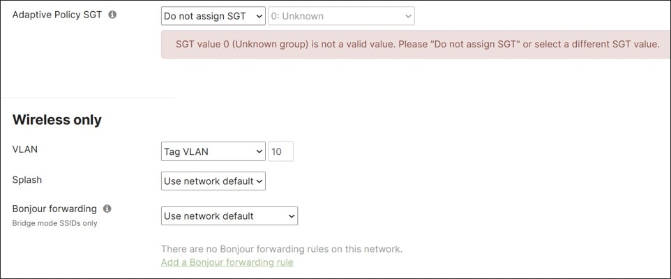
Wireless Access Point: Configure corporate SSID
Access control
Procedure 55. To configure Corp wireless access control:
Step 1. Go to Wireless > Configure > Access Control.
Tech tip: In order for Corporate WiFi with WiFi 7 to co-exist with a less secure Guest WiFi on the same AP, the SSIDs must be placed into separate SSID groups. The SSID group feature is still in BETA in the latest stable release candidate at the time of this writing, so the access points are still on the latest stable release (31.1.8) and are not yet upgraded. To prevent having to migrate to another SSID in the future, put the Corporate WiFi on a different SSID group from the less-secure Guest WiFi. There are four SSIDs per group (SSID #1-4, SSID #5-8, SSID #9-12, and SSID #13-15).
Step 2. Select an unconfigured SSID (in a separate SSID group from Guest Wi-Fi) from the drop-down menu, which can be any SSID from #5-15 in this example.
Step 3. Provide an SSID name (in this example, BR2-CorpWiFi) and next to SSID status, select Enabled. The SSID will not be hidden.
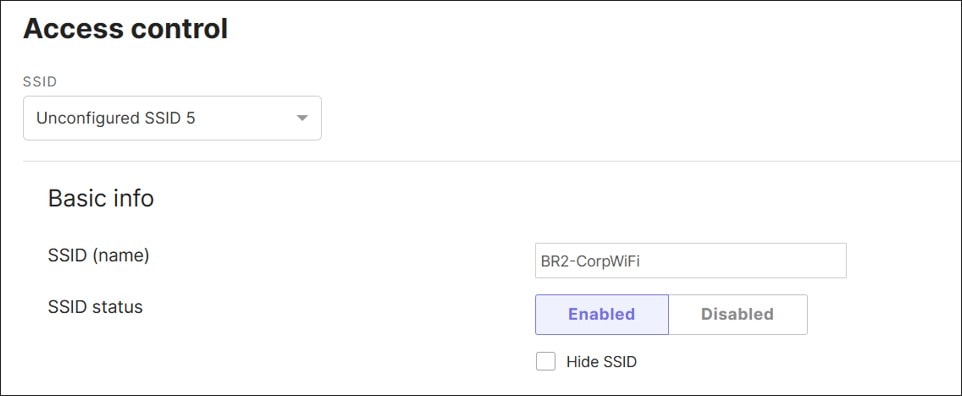
Step 4. Under Security, select Enterprise with my RADIUS server.
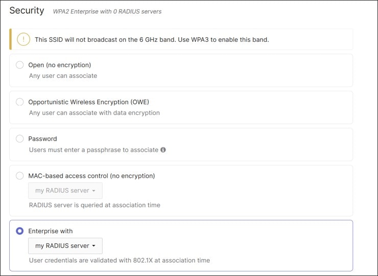
Step 5. Next to WPA encryption, select WPA3 Transition Mode.
Step 6. Next to 802.11w (management frame protection) verify that Enabled (allow unsupported clients) is selected.
Step 7. Next to Mandatory DHCP, select Enabled.
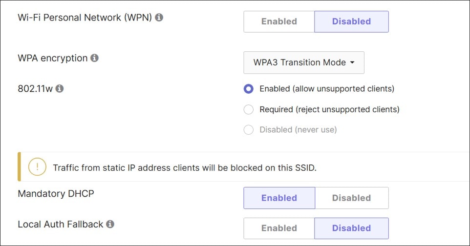
Step 8. Under the Splash page, verify that None (direct access) is selected.
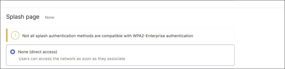
Step 9. Scroll down and click RADIUS to open the RADIUS settings.
Step 10. Under RADIUS servers, click Add server and enter the Host IP or FQDN (10.102.1.157), Auth (Authentication) port (1812), and Secret password.
Step 11. Optionally, test the server connectivity.
Step 12. Click Done.
Step 13. Under RADIUS accounting servers, select Add server and enter the Host IP or FQDN (10.102.1.157), Acct (Accounting) port (1813), Secret password, and click Done.
Step 14. RADIUS CoA is not enabled due to the enabling of the fast-roaming feature. Next to RADIUS attribute specifying group policy name, verify that Filter-Id is selected.
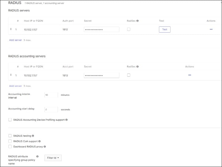
Step 15. Under Client IP and VLAN, select External DHCP server assigned and verify Bridged mode is selected.
Step 16. Next to RADIUS override, verify that Override VLAN tag is selected.
Step 17. Under VLAN tagging, select VLAN ID, and under VLAN ID, type in 10. This is the default VLAN for authenticated users if VLAN IDs or group policy names are not passed by RADIUS. VLAN 10 is the DATA VLAN already defined on the MX router and carried on the trunk between the AP/switch and the MX router/switch.
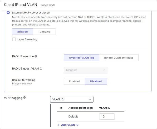
Step 18. Scroll back up to the Security section.
Step 19. Next to 802.11r (fast roaming) select Enabled. This feature is not available under Meraki AP assigned (NAT mode) and becomes available when External DHCP server assigned is selected. In this version of code, fast roaming cannot be enabled if RADIUS CoA support is enabled.
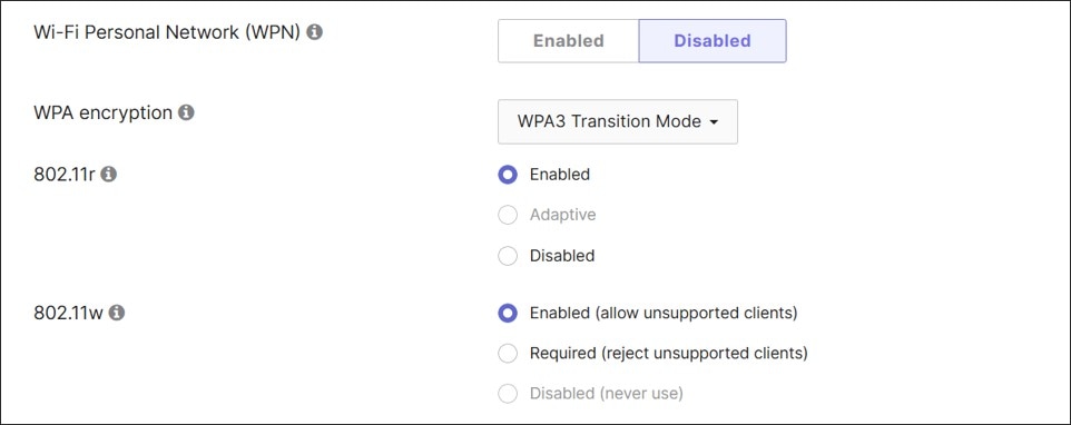
Step 20. Click Save.
Firewall and traffic shaping
Procedure 56. To configure Corp wireless firewall and traffic shaping:
Step 1. Under Wireless > Firewall & Traffic Shaping, select the Corp SSID from the drop-down menu (BR2-CorpWiFi).
Step 2. Leave the defaults. The configuration should look like:
● Block IPs and ports
◦ Layer 2 LAN isolation: disabled
◦ DHCP guard: Disabled
◦ RA guard: Enabled
◦ Outbound rules: Allow IPv4 Any Local LAN Any (Wireless clients accessing LAN)
◦ Outbound rules: Allow IPv4 Any Any Any (Default rule)
● Traffic shaping rules
◦ Per-client bandwidth limit: unlimited
◦ Per-SSID bandwidth limit: unlimited
◦ Shape traffic: Shape traffic on this SSID
◦ Default Rules: Enable default traffic shaping rules
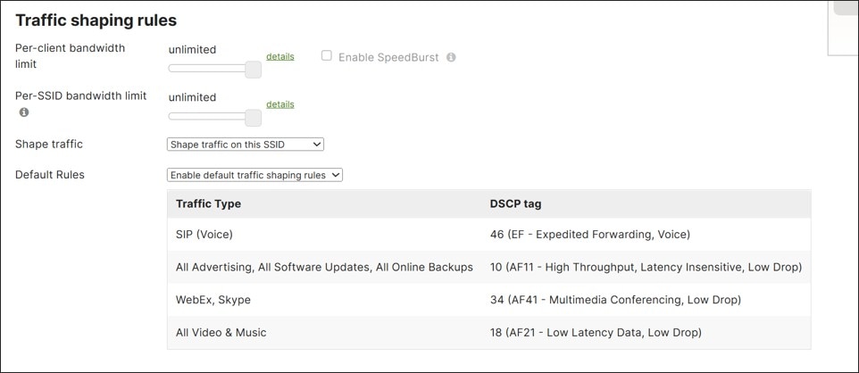
Wireless Access Point: Configure SSID availability
Procedure 57. To configure SSID availability:
Step 1. Go to Wireless > Configure > SSID Availability and select an SSID (BR2-CorpWiFi).
Step 2. Next to Scheduled availability, select enabled.
Step 3. Next to Schedule templates, ensure Custom schedule is selected.
Step 4. Configure these schedules:
● Sunday, unavailable, From 0:00 to 24:00
● Monday-Friday, available, From 7:00 to 19:00
● Saturday, unavailable, From 0:00 to 24:00
Step 5. Click Save Changes.
Step 6. Repeat for other SSIDs (BR2-GuestWiFi).
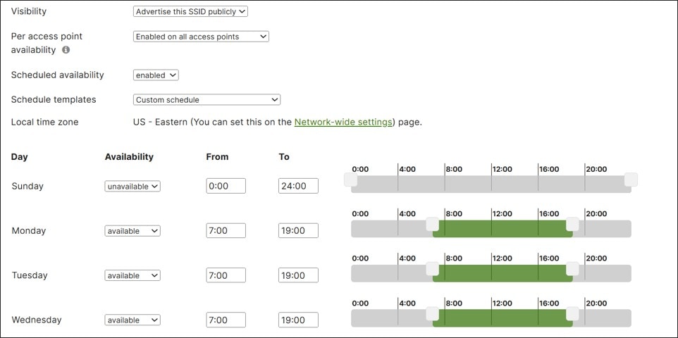
Wireless Access Point: Configure radio settings
Procedure 58. To configure radio settings:
Step 1. Go to Wireless > Configure > Radio Settings. Select the RRM tab.
Step 2. Next to AI-RRM, select Enable.

Step 3. Click Save changes at the bottom of the page.
Step 4. Under Wireless > Configure > Radio Settings, select the RF profiles tab.
Step 5. Copy the Basic Indoor Profile.
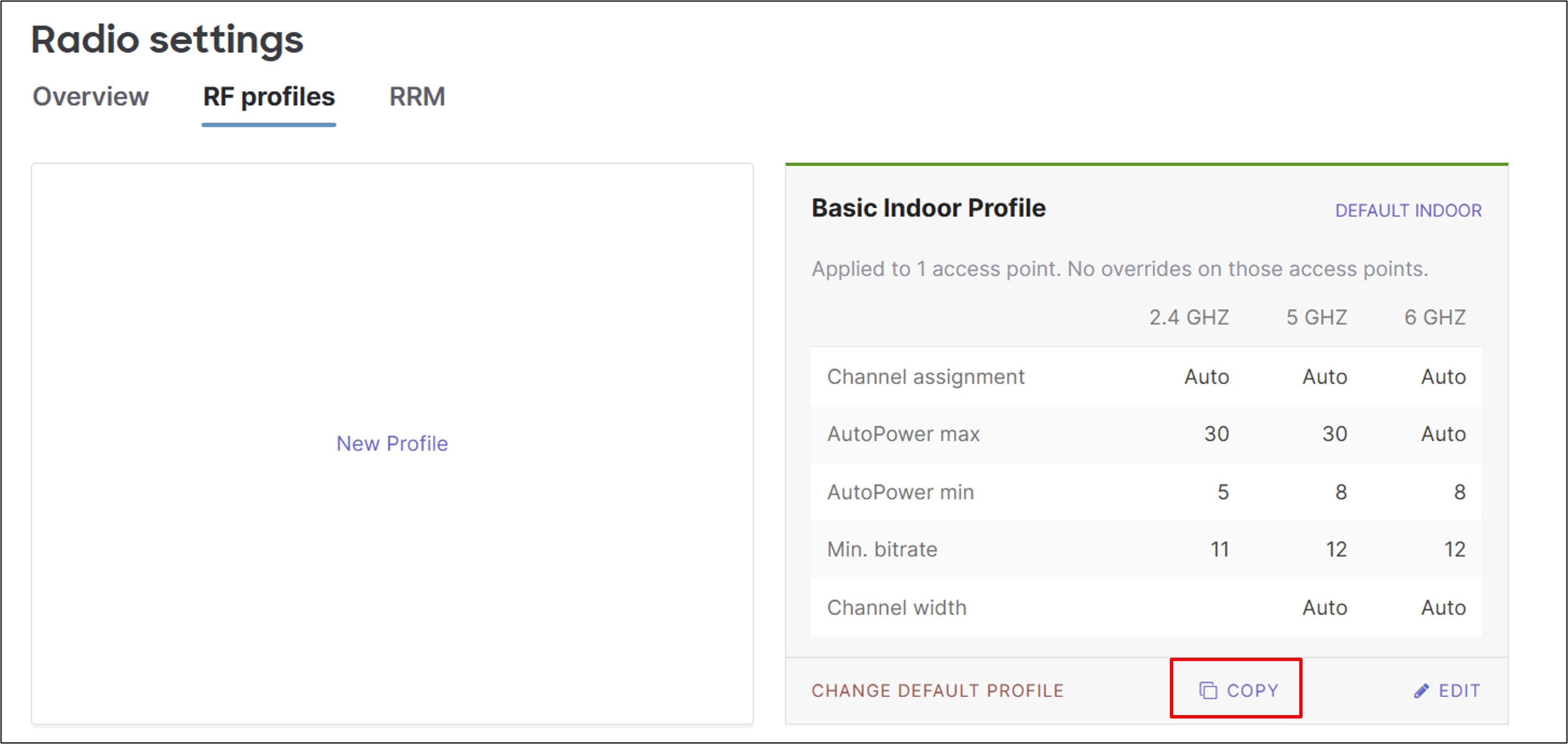
Step 6. Next to Profile name, type a new name (Medium Branch Profile).
Step 7. Next to Band selection, select Per SSID, and enable 6 GHz and Band steering for BR2-CorpWiFi (2.4 GHz and 5 GHz should already be selected for both BR2-GuestWiFi and BR2-CorpWiFi).
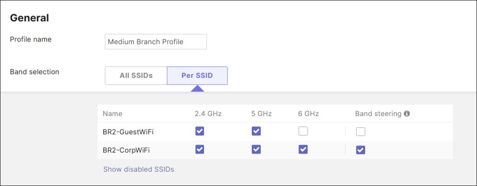
Step 8. Click Save.
Procedure 59. To associate the AP with the newly edited RF profile:
Step 1. Go to Wireless > Configure > Radio Settings and select the Overview tab.
Step 2. Select the AP and click Edit settings.
Step 3. From the drop-down menu, select Assign profile.
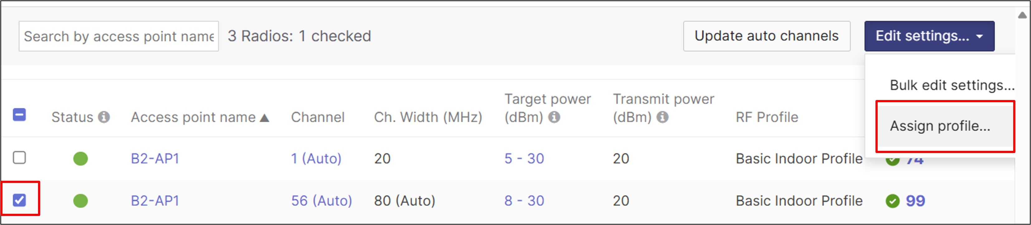
Step 4. Select the Medium Branch Profile and click Next.
Step 5. A window pops up that states that some access points have manually configured settings (power, channel, and channel-width settings) which override profile settings. Clear their manual overrides if needed and select Review changes.
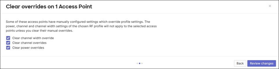
Step 6. Click Apply changes.
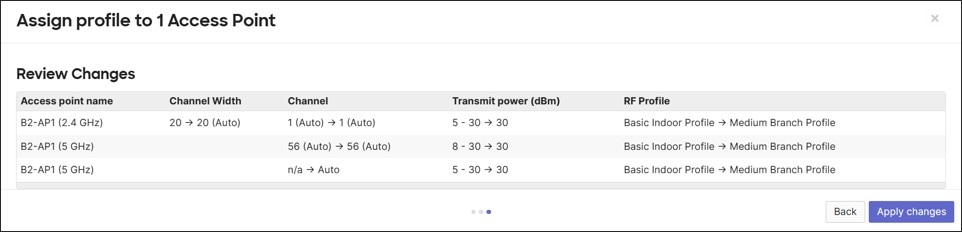
Configure other network services
SNMP (dashboard polling)
This is configured at the Organization level.
Procedure 60. To configure SNMP, if not already configured:
Step 1. Go to Organization > Configure > Settings.
Step 2. Under SNMP, verify these settings are configured:
● SNMP V2C disabled
● SNMP V3 enabled
● Authentication mode: SHA
● Privacy mode: AES128
Step 3. Verify strong passwords are set for Authentication and Privacy and configure any IP restrictions (public IP address endpoints that are authorized to poll the dashboard).
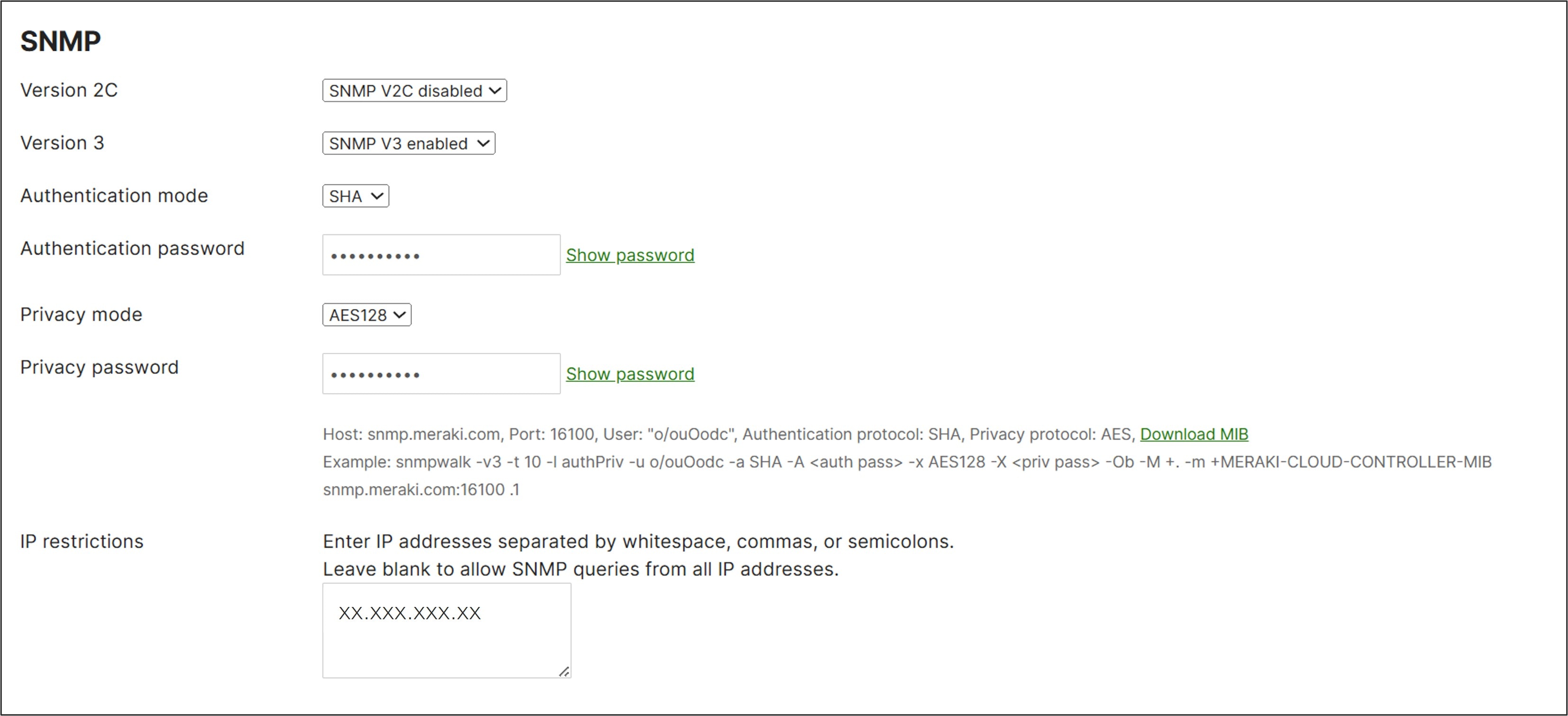
SNMP (dashboard traps)
Procedure 61. To configure SNMP traps:
Step 1. Go to Network-wide > Configure > Alerts > SNMP traps.
Step 2. Next to Access, select V3 (username/password).
Step 3. Click Add an SNMP user and fill out an SNMP Username and Passphrase. The same passphrase is used for authentication and privacy. The authentication protocol is SHA1, and privacy protocol is AES128.
Step 4. Enter the public IP address of the server that will receive the SNMP traps and configure its receiving port as well.
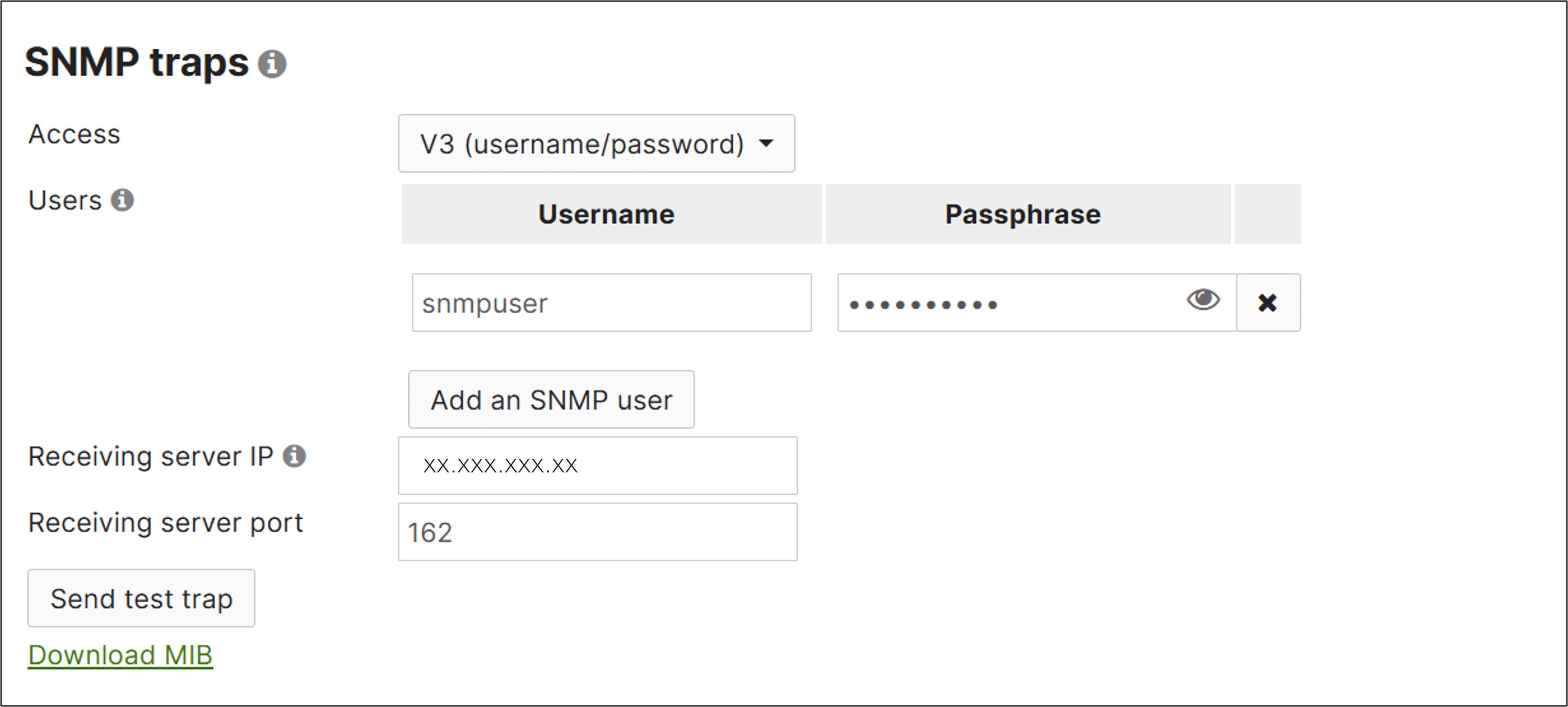
Step 5. Scroll up to Alerts Settings.
Step 6. Add snmp in the Default recipients box and select any conditions where alerts should be triggered. These are the conditions selected for alerts in this example:
● Network-wide: A rogue access point is detected
● WAN appliance: Malware is downloaded
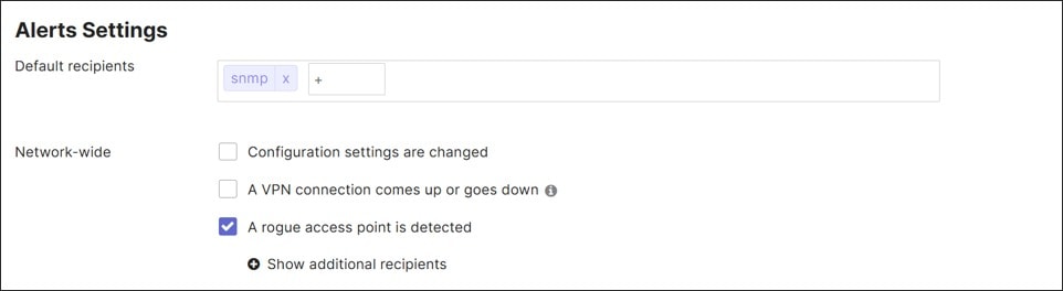
Step 7. Click Save.
Syslog
This is configured at the network level.
Procedure 62. To configure syslog for the network devices:
Step 1. Go to Network-wide > Configure>General.
Step 2. Under Reporting > Syslog servers, click + Add a syslog server. Enter these values:
● Server address (10.102.1.160)
● Port (514)
● Protocol (UDP)
● Roles (Wireless Event log, Wireless Air Marshal events, Switch Event log, Appliance Event log, Appliance Security events)
Step 3. Click Update syslog servers.

Step 4. Click Save Changes.
SNMP (device polling)
The SNMP device polling configuration is done at the network level.
Procedure 63. To configure SNMP device polling:
Step 1. Go to Network-wide > Configure > General.
Step 2. Under Reporting next to SNMP access, configure V3 (username/password).
Step 3. Click Add an SNMP user and configure an SNMP Username and strong Passphrase that will be used for the authentication and privacy passwords.
Step 4. For Privacy Mode, select AES128 (the Authentication Algorithm protocol will be SHA1).
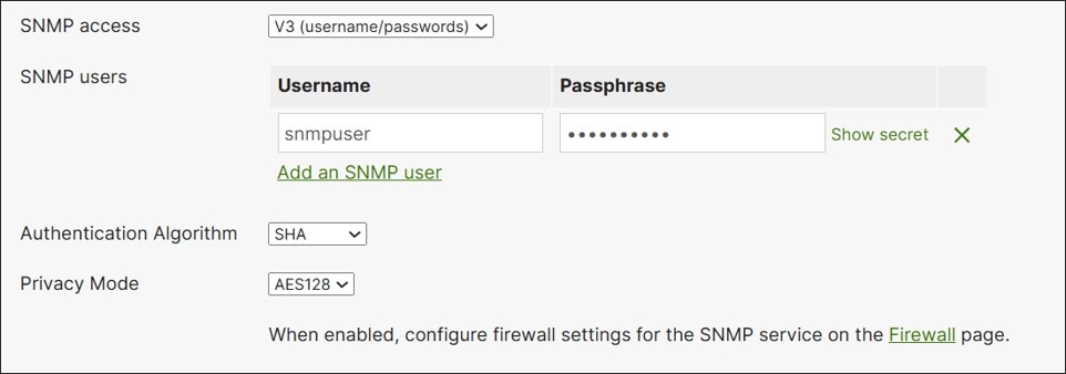
In this example, the SNMP server is in the data center and rules are already configured to allow the traffic in the outbound VPN firewall, so no further configuration is needed.
Step 5. Click Save or Save Changes.
NetFlow
This is configured at the network level.
Procedure 64. To configure NetFlow:
Step 1. Go to Network-wide > Configure > General.
Step 2. Under Reporting next to NetFlow traffic reporting, select Enabled: send netflow traffic statistics.
Step 3. Next to NetFlow collector IP, type the IP address of the NetFlow collector.
Step 4. Next to NetFlow collector port, type the port number of the NetFlow collector.
Step 5. Click Save or Save Changes.
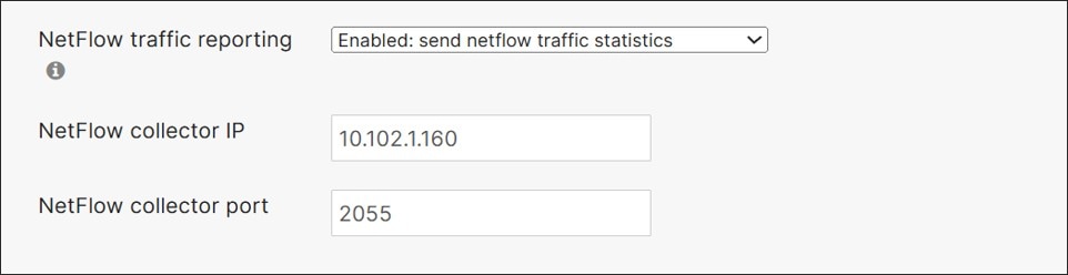
In this example, NetFlow is only enabled for the MX router since it is not supported on MS switches.
Organization: Configure Adaptive Policy
Adaptive Policy is enabled at the Organization level. When Adaptive Policy is enabled for a network, additional configuration options for adaptive policy appear in the MX site-to-site VPN configuration, MX port configurations, and switch port configurations.
Note: The C81xx series routers do not properly propagate SGT tags under certain software versions. This is fixed in MX version 26.1.4.
If groups and Adaptive Policy have already been defined, skip to the Enable Networks for Adaptive Policy section.
In this example, 4 groups are created which are all part of the DATA VLAN. Finance users can communicate with Finance servers and Marketing users but cannot reach Marketing servers. Marketing users can communicate with Marketing servers and Finance users but cannot reach Finance servers.
Procedure 65. To configure Adaptive Policy groups:
Step 1. On the dashboard, go to Organization > Adaptive Policy.
Step 2. Click the Groups tab. Click + Add group.
Step 3. Configure a Name (Finance_User_Group), SGT Value (10), and Description (Finance User Group).
Step 4. Click Create.
Step 5. Repeat until the group configuration is complete.
| Name |
SGT value |
Description |
| Finance_User_Group |
10 |
Finance User Group |
| Marketing_User_Group |
20 |
Marketing User Group |
| Finance_Server_Group |
100 |
Finance Server Group |
| Marketing_Server_Group |
200 |
Marketing Server Group |
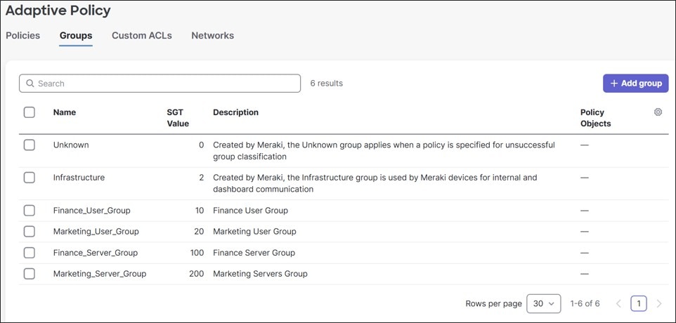
Traffic policies can now be created.
Procedure 66. To create Adaptive Policy traffic policies:
Step 1. On the Adaptive Policy page, click the Policies tab.
Step 2. Click + Add policies.
Step 3. Under Source groups, select a Name (Finance_User_Group), then under Destination groups, select all groups that will be allowed (Finance_User_Group, Marketing_User_Group, and Finance_Server_Group).
Step 4. At the top of Destination groups, click Allow.
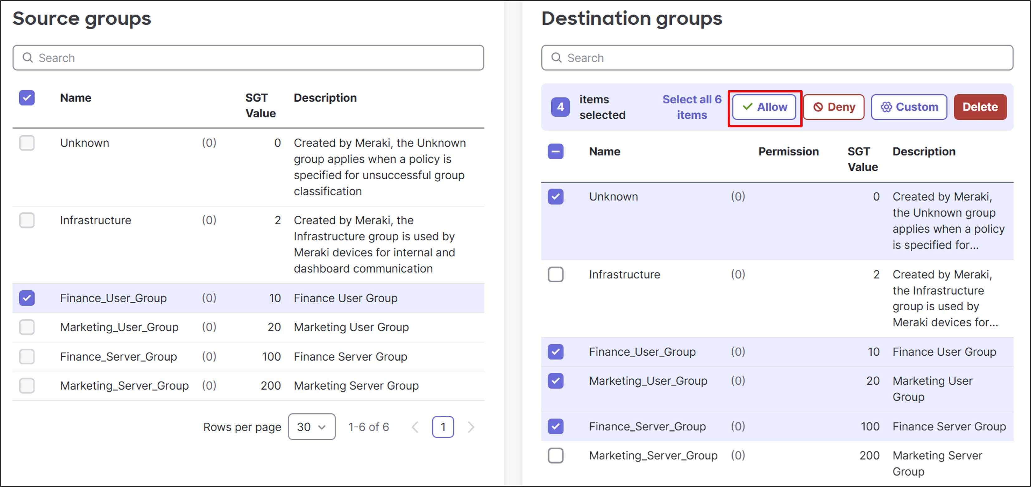
Step 5. A window pops up and displays the changes. A box can be checked to automatically create the inverse policy. An error occurs if a reverse policy already exists. In this case, do not automatically create the inverse policy since Finance_User_Group à Finance_User_Group would attempt to be created twice, generating an error. Click Allow.
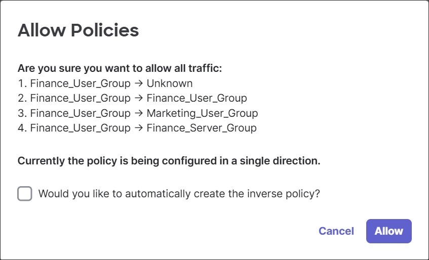
Step 6. Continue adding policy, selecting Allow or Deny between groups.
Note: In this example, Unknown and Infrastructure groups are permitted to reach all other defined groups. This is so Finance and Marketing devices can ping their IP default gateways and perform other troubleshooting and monitoring tasks.
| Group |
Unknown |
Infra- |
Finance_User_Group |
Marketing_User_Group |
Finance_Server_Group |
Marketing_Server_Group |
| Unknown |
|
|
Allow |
Allow |
Allow |
Allow |
| Infrastructure |
|
|
Allow |
Allow |
Allow |
Allow |
| Finance_User_ |
Allow |
Allow |
Allow |
Allow |
Allow |
Deny |
| Marketing_User_ |
Allow |
Allow |
Allow |
Allow |
Deny |
Allow |
| Finance_Server_ |
Allow |
Allow |
Allow |
Deny |
Allow |
Deny |
| Marketing_Server_ |
Allow |
Allow |
Deny |
Allow |
Deny |
Allow |
Step 7. View the resulting policy in grid format or list format, which can be selected in the upper right corner of the Adaptive Policy page:
.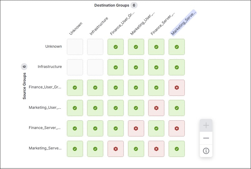
Enable networks for Adaptive Policy
Procedure 67. To enable Adaptive Policy in individual branches:
Step 1. Go to Organization > Adaptive Policy and click on the Networks tab.
Step 2. Select the branches that need to be enabled for Adaptive Policy then click Enable.
Step 3. Verify DC1 and DC2 hub sites are also enabled.
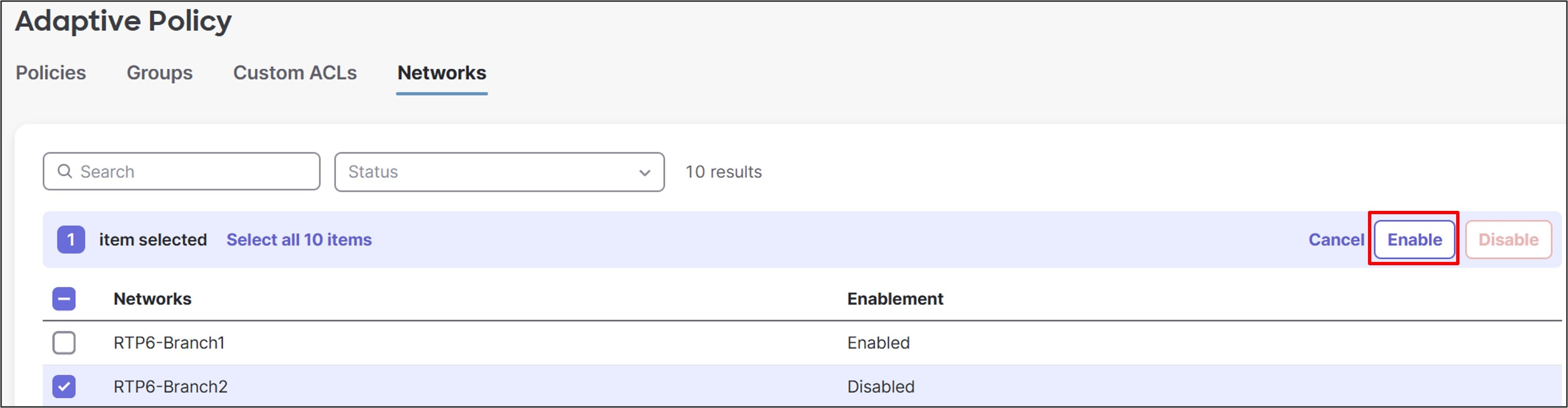
Step 4. A pop-up window may caution that making modifications to the Adaptive Policy on a network may cause a momentary disruption of all traffic due to SGT configuration changes. Click Enable.
RTP6-Branch2 is now enabled for the Adaptive Policy.
To ensure tags can be propagated from end-to-end, Auto VPN and trunk ports in the branches need to be enabled as “Peer SGT capable”. Assignment of SGTs in this example network is done through RADIUS when a client joins the network.
Auto VPN configuration
Procedure 68. To configure Adaptive Policy for Auto VPN:
Step 1. Go to Network RTP6-Branch2.
Step 2. Go to Security & SD-WAN > Configure > Site-to-site VPN.
Step 3. Under VPN settings next to Peer SGT capable, select Enabled.
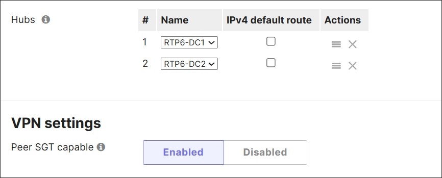
Step 4. Click Save or Save Changes.
Step 5. Repeat the configuration for sites that need SGT tag propagation over Auto VPN (DC1, DC2, and any other branch sites).
Both Auto VPN peers are now enabled to allow for SGT tag propagation. In the hub and spoke topology, the data center hubs need this configuration in order for SGT tags to be propagated from site to hub and from site to site.
LAN trunk configuration
Before SGT tags can be propagated to a neighbor on the LAN, the trunk port to that neighbor needs to be marked as Peer SGT capable.
Procedure 69. To configure Adaptive Policy for LAN trunks:
Step 1. For the MX router, go to Security & SD-WAN > Configure > Addressing & VLANs.
Step 2. Select the ports to the LAN switches (Ports 5 and 6 in this example) then click Edit at the top next to Per-port VLAN Settings.
Step 3. Next to Peer SGT capable, select Enabled.
Step 4. Next to Adaptive policy, from the drop-down menu, select a group (2: Infrastructure (Predefined)) to add to untagged traffic, which should be device management and dashboard traffic.
Step 5. Click Update.
Step 6. Click Save.
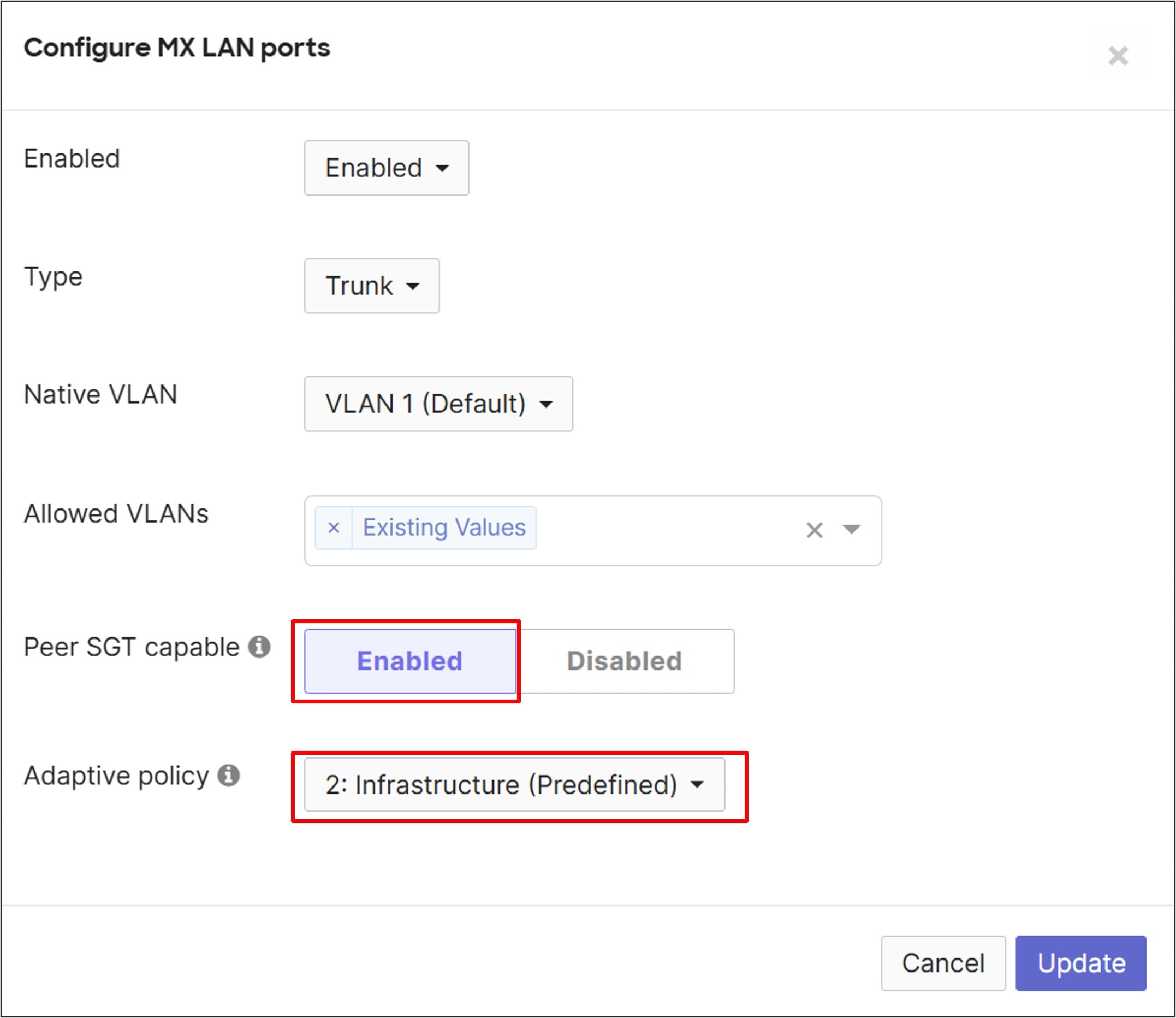
On the switches, the trunks to the MX routers and the trunk to the AP will both have to be marked as Peer SGT capable.
Step 7. Go to Switching > Monitor > Switch Ports.
Step 8. Select all uplink ports to the MX routers (B2-SW1/1, B2-SW1/2, B2-SW2/1, and B2-SW2/2 and the port to the AP (B2-SW1/9) and click Edit.
Step 9. Next to Peer SGT capable, click Enabled.
Step 10. Next to Adaptive policy group, select 2: Infrastructure from the drop-down menu.
Step 11. Click Update.
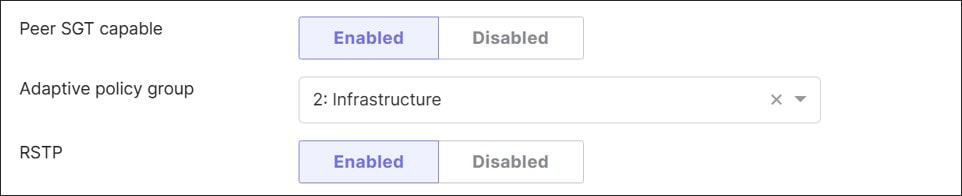
The AP automatically detects SGT tags coming from the switch and will then send SGT-tagged traffic, so no manual configuration is required on the AP.
Step 12. Repeat for other sites.
Organization configuration: ThousandEyes
ThousandEyes must be enabled on a network-by-network basis.
Procedure 70. To configure ThousandEyes integration:
Step 1. Go to Insight > Configure > Active Application Monitoring.
Step 2. If ThousandEyes has already been set up, a list of monitored networks appears. Follow these steps to continue:
a. To add monitoring for another application or network, click the Add tests button.
b. ThousandEyes shows as connected to a specific account group that was previously configured. Click Next.
c. Skip to the Application selection section.
Step 3. If ThousandEyes has not been configured yet, click Get started.
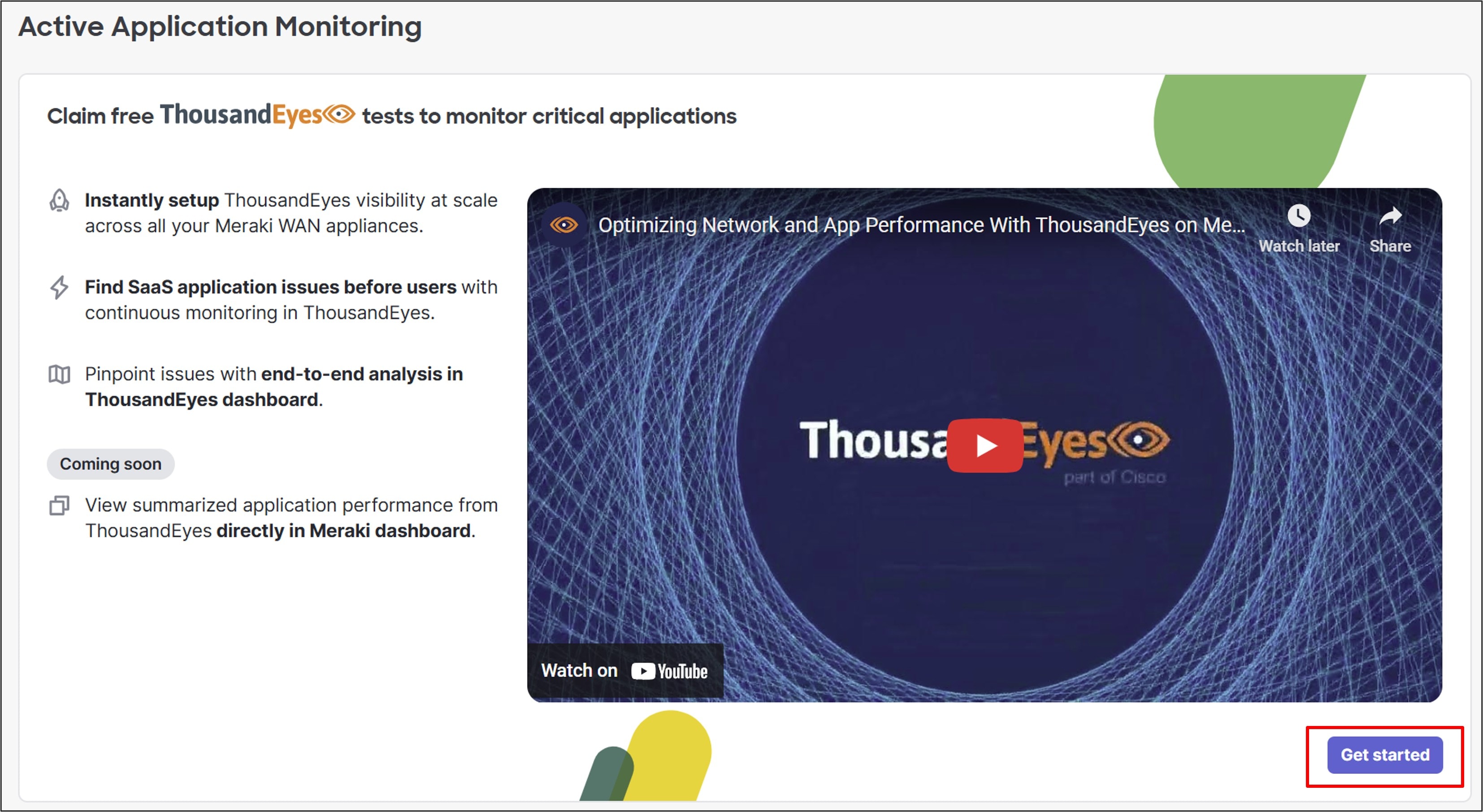
Step 4. Click Authenticate if you have an existing ThousandEyes account (or click Create new account). This example workflow assumes a ThousandEyes account already exists.
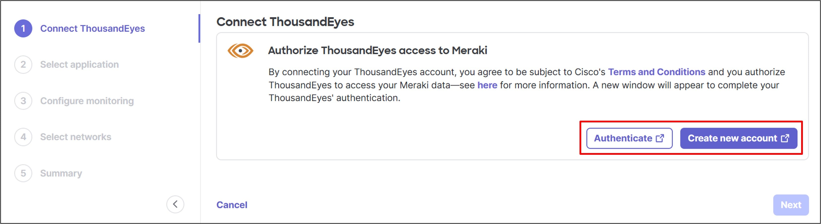
Step 5. After clicking Authenticate, a window pops up to log into Cisco ThousandEyes. Enter the email address and optional region. The region for ThousandEyes should be in the same region as Meraki. Click Log In.
Step 6. In the next window, type in the password, then click Next.
Step 7. A window pops up explaining what Cisco Meraki is authorized to do when the integration is complete. Click Confirm.
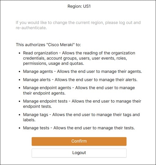
The authentication to ThousandEyes is now complete.
Step 8. Back on the Meraki Dashboard, select an account group from ThousandEyes from the drop-down menu to pair with Meraki and click Confirm.
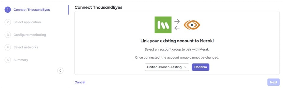
Step 9. The account group shows up as connected. Then click Next.
In this example, Office 365 Suite is selected.
Procedure 71. To select an application to monitor:
Step 1. Select an application to monitor with enhanced application monitoring. Alternatively, add a custom application, or continue without an application for now.
Step 2. Click Next.

Network selection
In this example, RTP6-Branch2 is selected.
Procedure 72. To select networks to activate ThousandEyes agents on:
Step 1. To run application tests, select the networks to activate ThousandEyes agents on, then click Next.
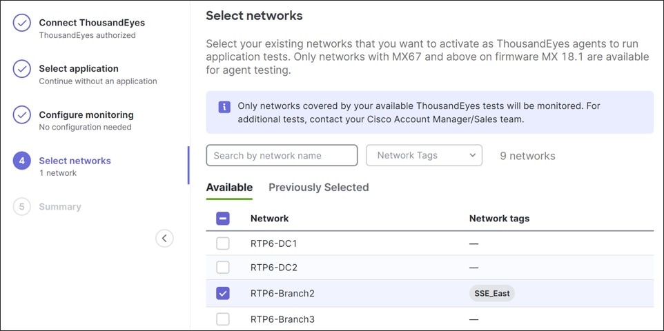
Step 2. Click Start monitoring.
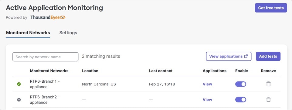
Step 3. After a brief period of time, the monitored network shows active. Click View applications to go directly to the ThousandEyes dashboard.
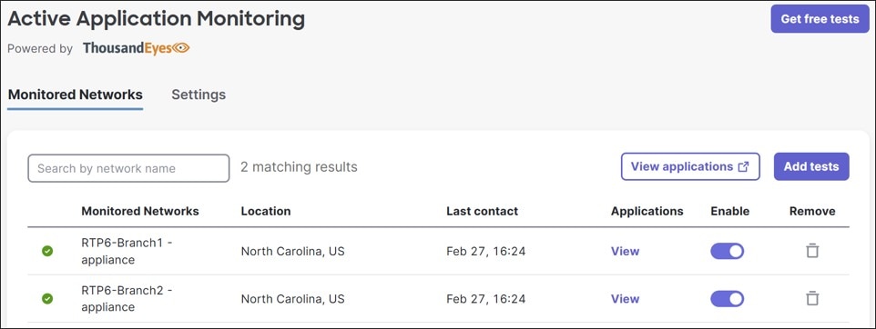
Step 4. Skip the prompts to set up monitoring by deploying templates. The agent can be seen from the ThousandEyes dashboard.
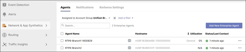
Organization configuration: Splunk
Basic Splunk integration is at the Meraki organization level. If it is not already configured, follow these steps:
Procedure 73. To integrate Splunk:
Step 1. Before integrating the Meraki Dashboard Organization with Splunk, go to the Dashboard and retrieve the Organization ID and Organization API Key.
Step 2. On the Meraki Dashboard, go to the bottom of any page and record the organization ID.
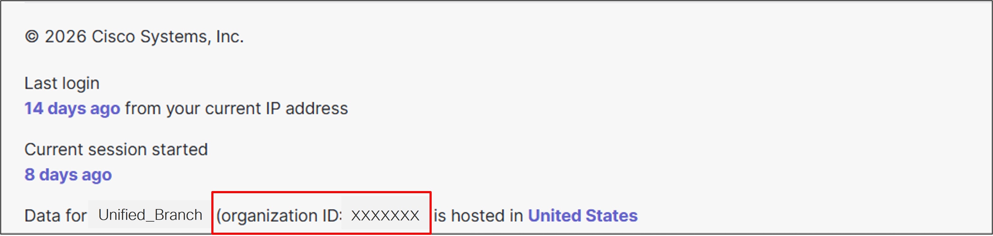
Step 3. To generate an API key, on the Meraki Dashboard, go to Organization > Configure > API & Webhooks, then go to the API keys and access tab.

Step 4. Click Generate API Key. Copy the API key to use in the Splunk integration.
Note: The API key is generated, and this is the only chance to record it. If it is forgotten, it will need to be revoked and a new one generated.
Step 5. Select I’ve stored my API key and click Done.
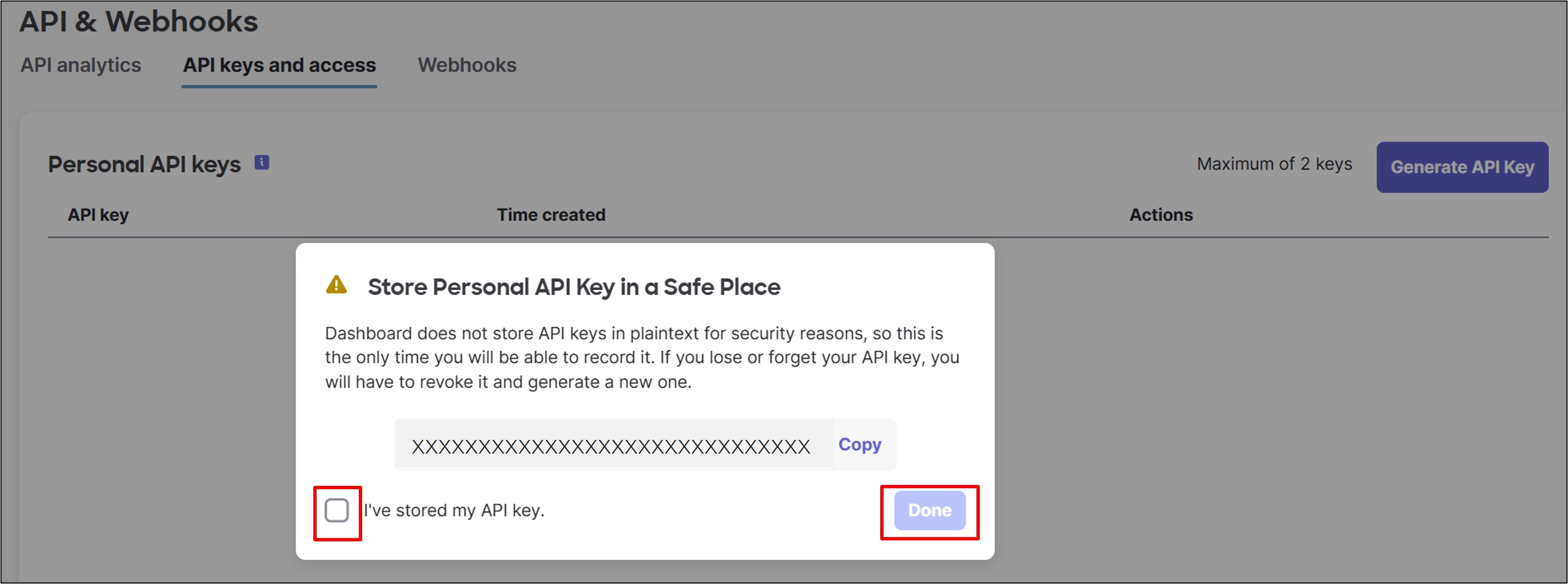
Step 6. Log into the Splunk dashboard.
Step 7. On the left-side, click Splunk Add-on for Cisco Meraki.
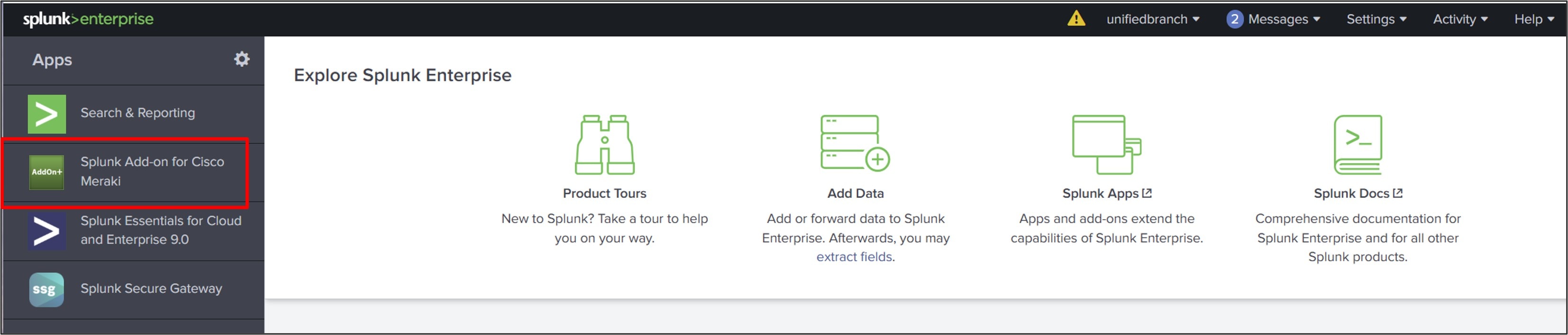
Step 8. Go to Configuration > Organization tab then click Add. In the pop-up window, enter values for these fields:
● Organization Name:
● Service region:
● Organization ID:
● Organization API Key:
● Max API calls per second:
● Create inputs* automatically?
*Inputs refer to the data sources that Splunk collects from Cisco Meraki devices and networks. These inputs allow users to monitor and analyze network data, including device status and alerts. If created automatically, all input types (except for webhook) are created in disabled mode.
Step 9. Click Add.
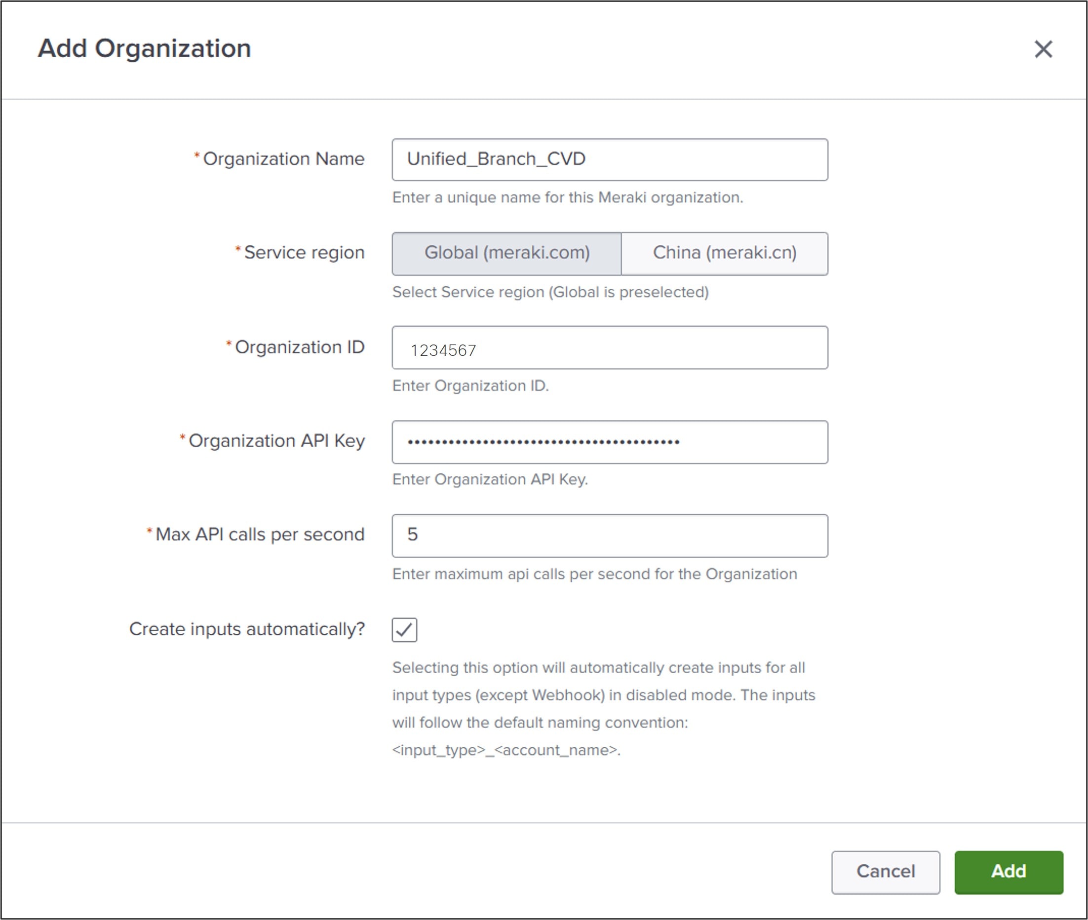
The Organization information is added to the Splunk Dashboard. Optionally, the logging level can be changed, or proxy information can be set up from this page.
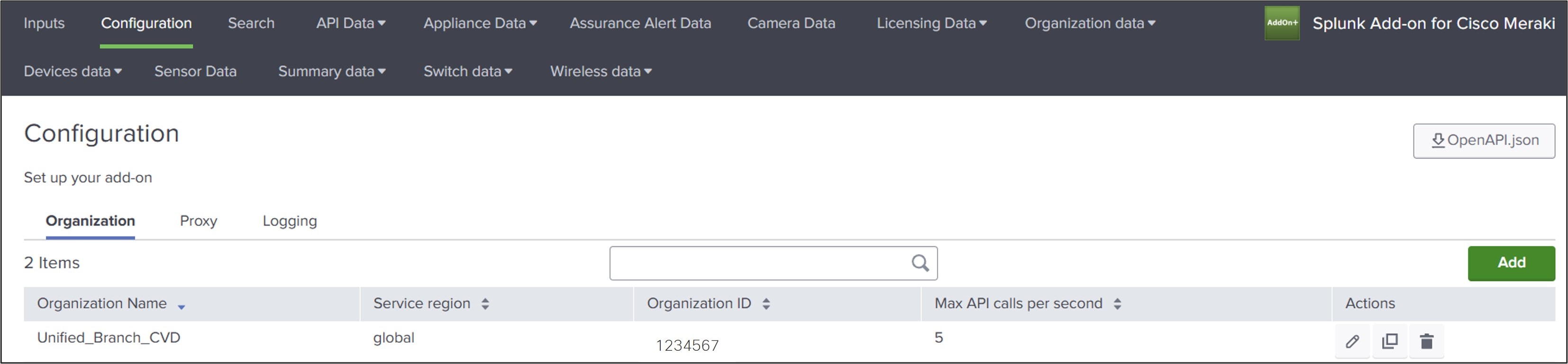
Step 10. To manage inputs, go to the Inputs tab on the Splunk dashboard and enable the ones of interest.
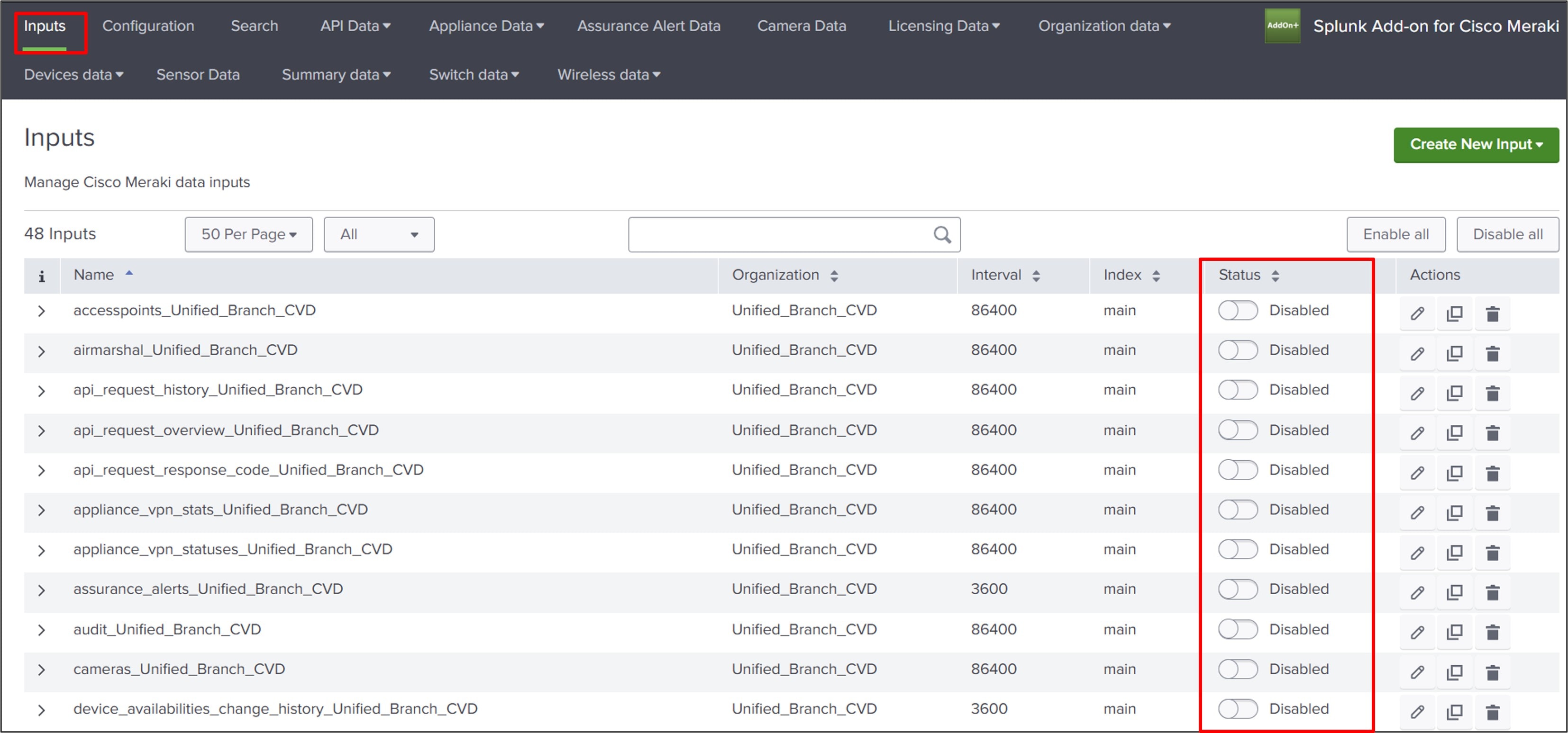
Webhooks can also be configured through the Dashboard for alerts on a network-by-network basis. Refer to Cisco Meraki Add-on for Splunk for additional information.
Organization configuration: XDR
The XDR integration to the Meraki Dashboard is performed once but is then enabled on a network-by-network basis. If XDR has already been integrated and is being enabled for additional networks, skip to the Enable Networks for XDR section.
Procedure 74. To integrate XDR:
Step 1. Go to Organization > Configure > Integrations.
Step 2. Select the Cisco XDR tile.
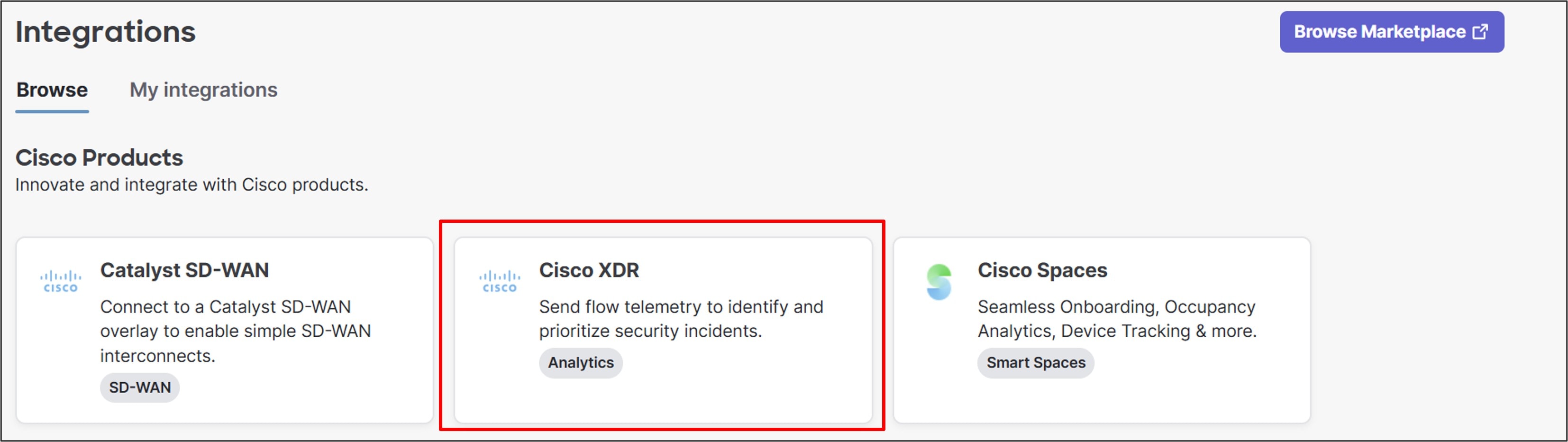
Step 3. From this window, if an XDR account does not exist, click Start a free trial. This workflow assumes an XDR account already exists.
Step 4. Click +Connect.
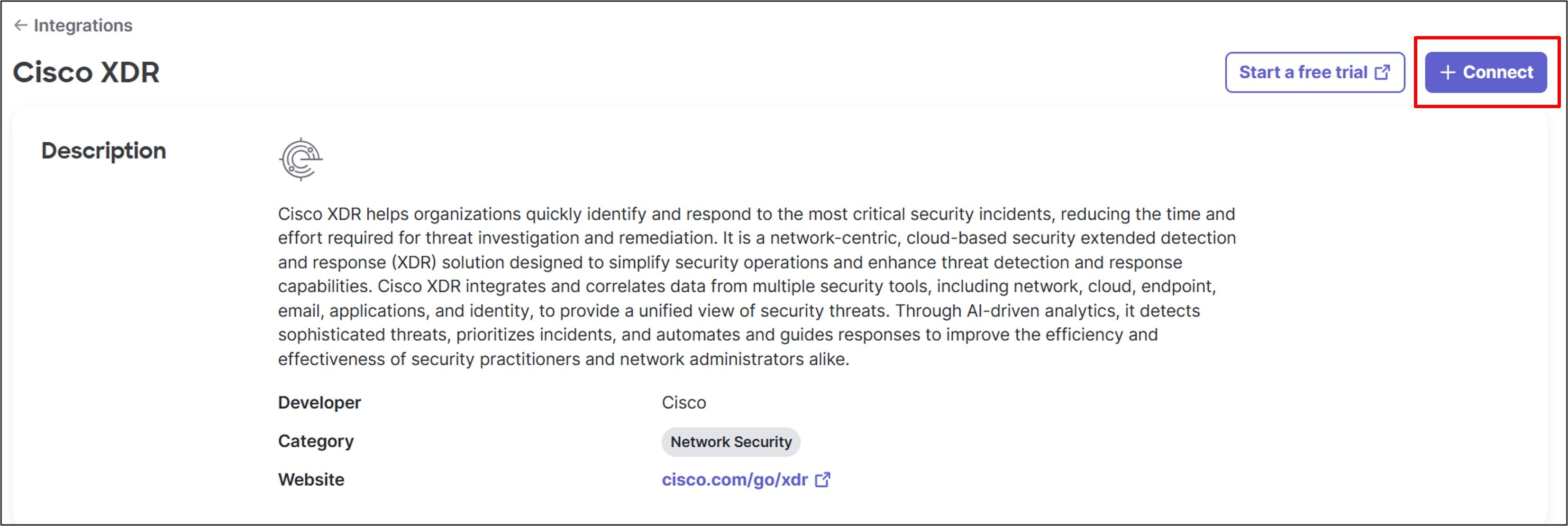
Step 5. Select the region where the XDR organization account is provisioned, then click Connect.
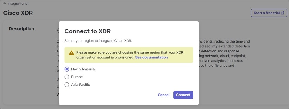
The login is verified and XDR is now connected and integrated in the Meraki Dashboard.
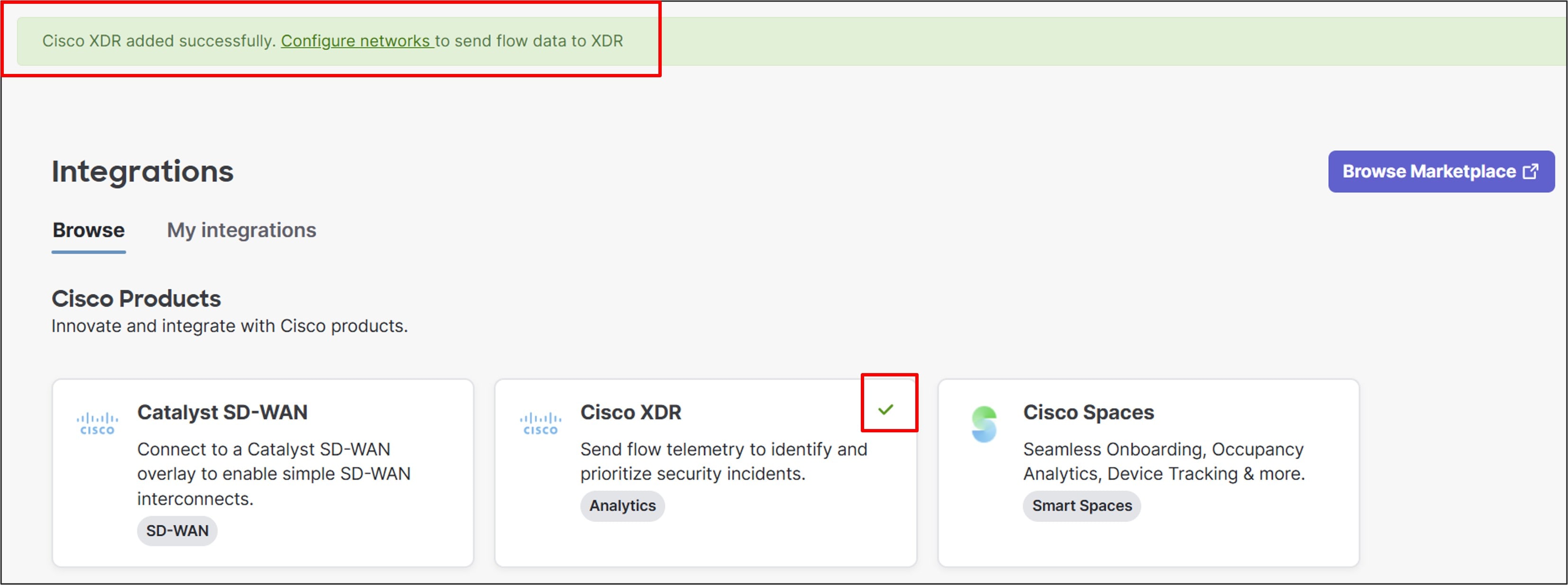
Step 6. View The Meraki Organization on the XDR dashboard under Administration > Integrations, in a list called My Integrations.
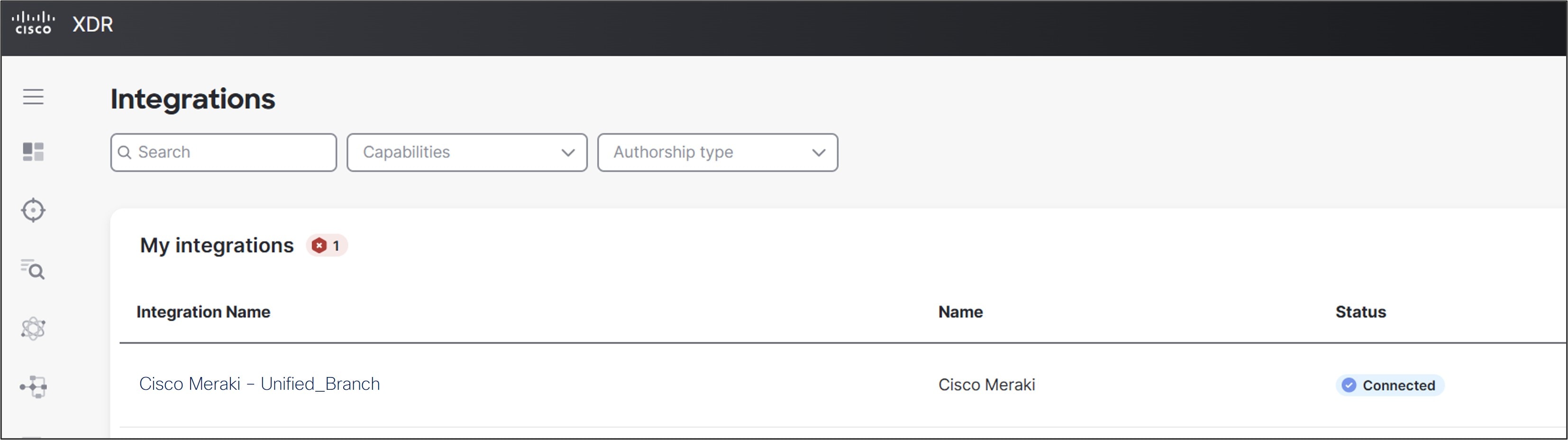
Enable networks for XDR
Procedure 75. To enable XDR for the network:
Step 1. Go to Organization > Integrations.
Step 2. Go to the My integrations tab.
Step 3. Click on the XDR integration with the Meraki Organization name.
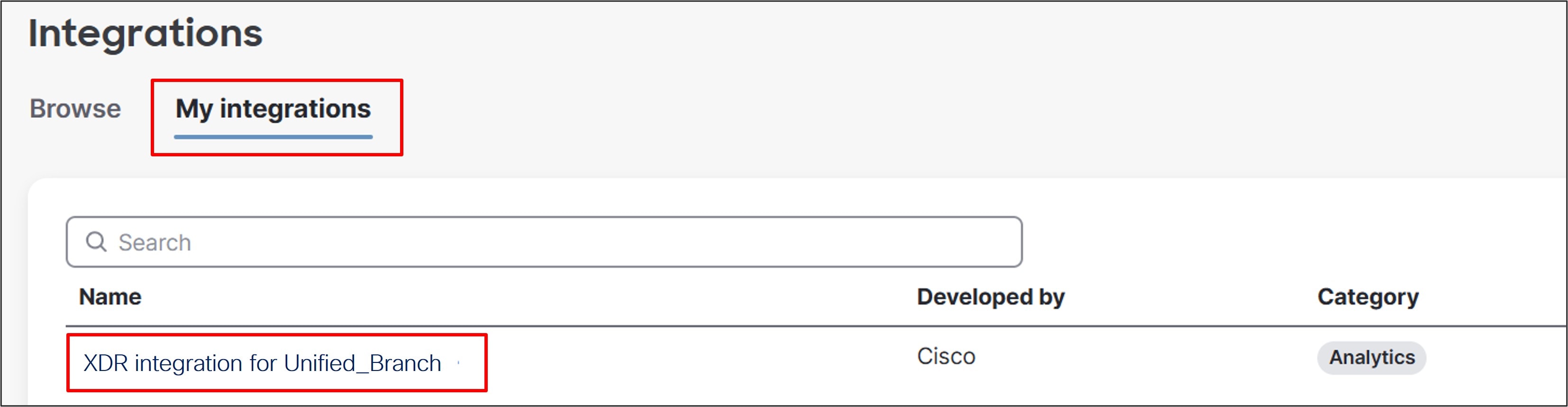
Step 4. Select Configure networks.
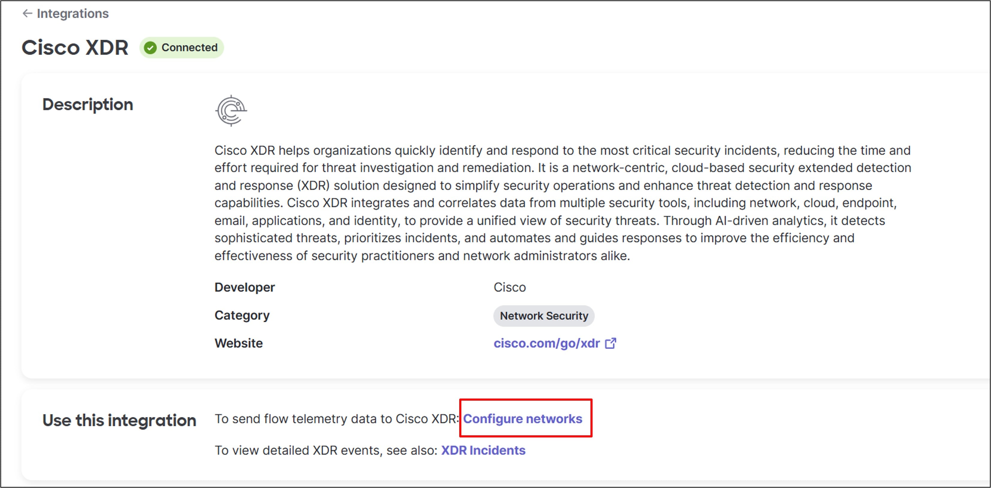
Step 5. Click the check box for RTP6-Branch2 to select it, then Enable.
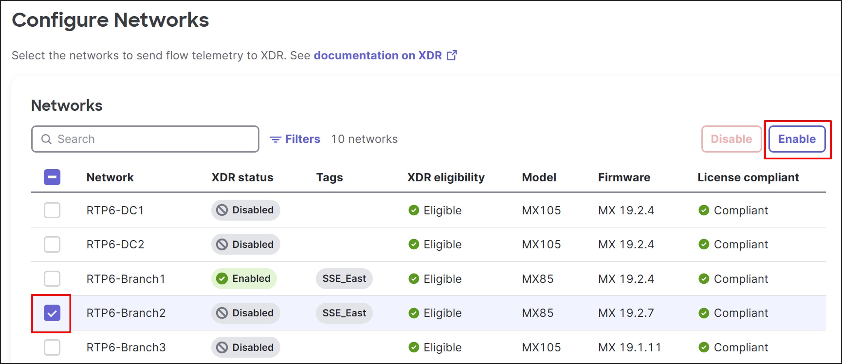
Step 6. A pop-up window asks to proceed with enabling XDR for RTP6-Branch2. Click Enable.
The XDR status for Branch 2 now shows Enabled.
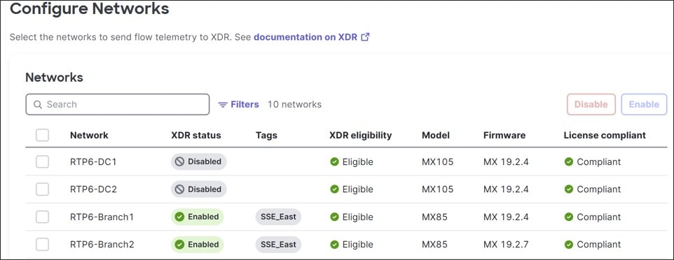
Data is now flowing to XDR.
Step 7. View XDR incidents from the Meraki Dashboard at Organization > Monitor > Security Center under the XDR Incidents tab.
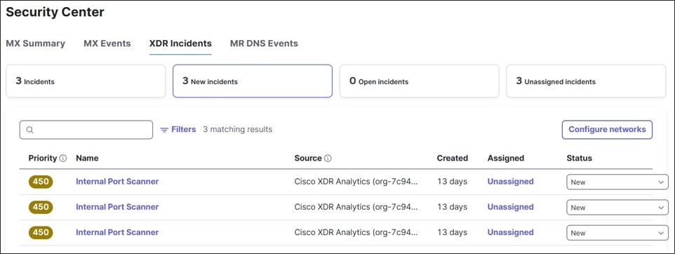
Verify the operation of the devices using the dashboard.
Procedure 76. To verify device operation:
Step 1. Go to Organization > Monitor > Overview to get a big-picture view of the network. Only dashboard connectivity-related alerts are reflected on this page.
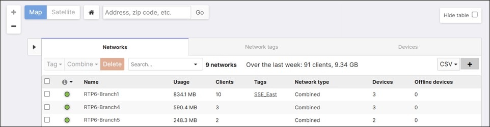
Step 2. Go to Organization > Monitor > Summary to get a more granular view of the device and uplink status for each network.
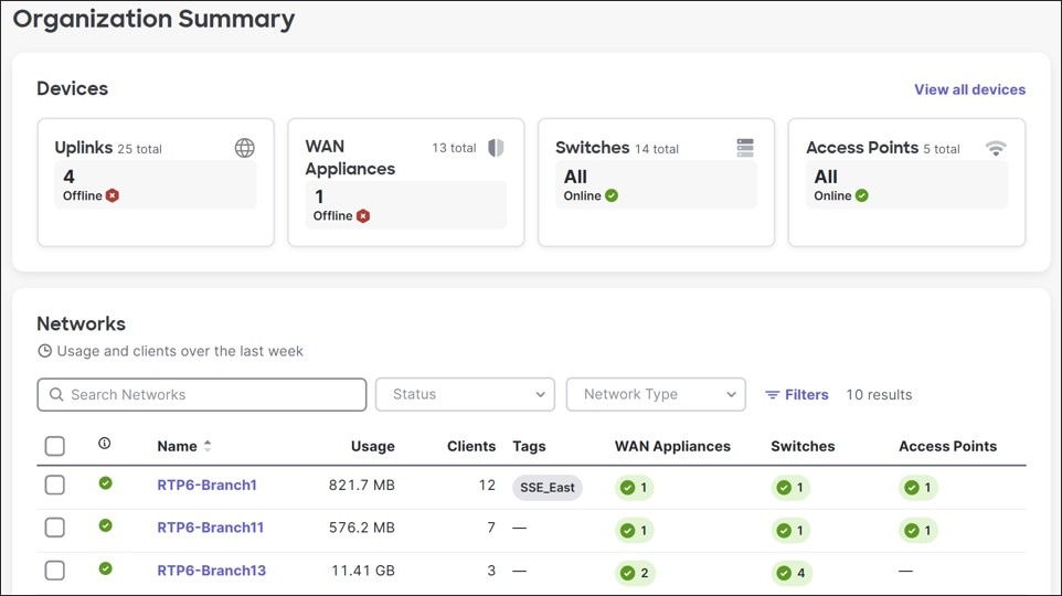
Step 3. Go to Organization > Monitor > Alerts to find additional alerts for the Organization.
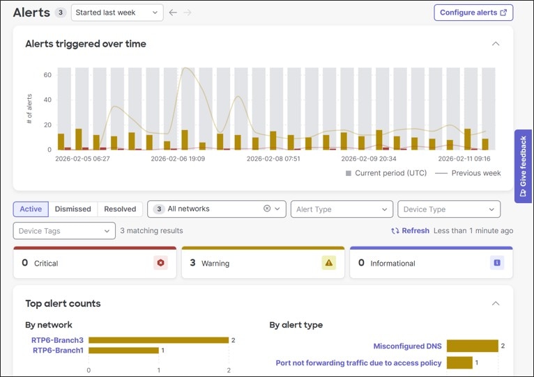
Procedure 77. To view an individual network:
Step 1. On the left of the dashboard (RTP6-Branch2), select the preferred Network.
Step 2. Select Network-wide > Monitor > Clients.
Step 3. Drill into any devices to review status, configurations, or troubleshoot issues. View clients connected to the network on this page as well.
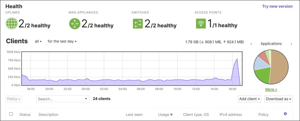
Step 4. View network-wide events by going to Network-wide > Monitor > Event Log and selecting the device type to view.
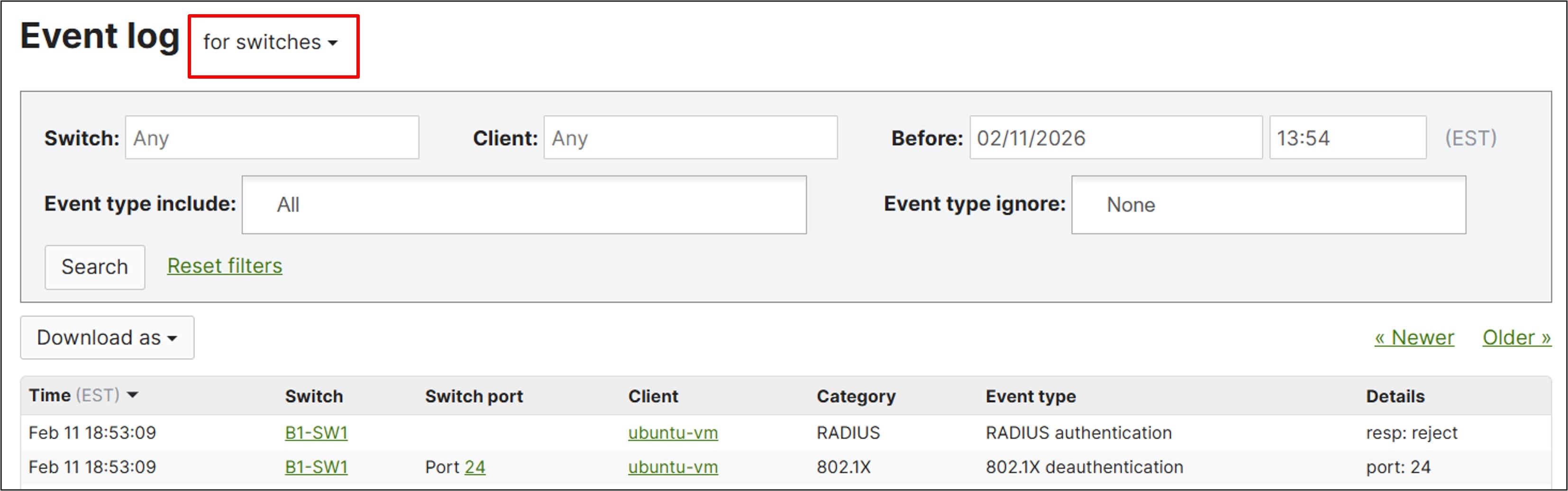
Procedure 78. To view IPsec tunnel status for Cisco Secure Access:
Step 1. Select the network and go to Security & SD-WAN > Monitor > VPN Status.
Step 2. Click the IPsec peers tab.
Step 3. Click Details for tunnel monitoring information.
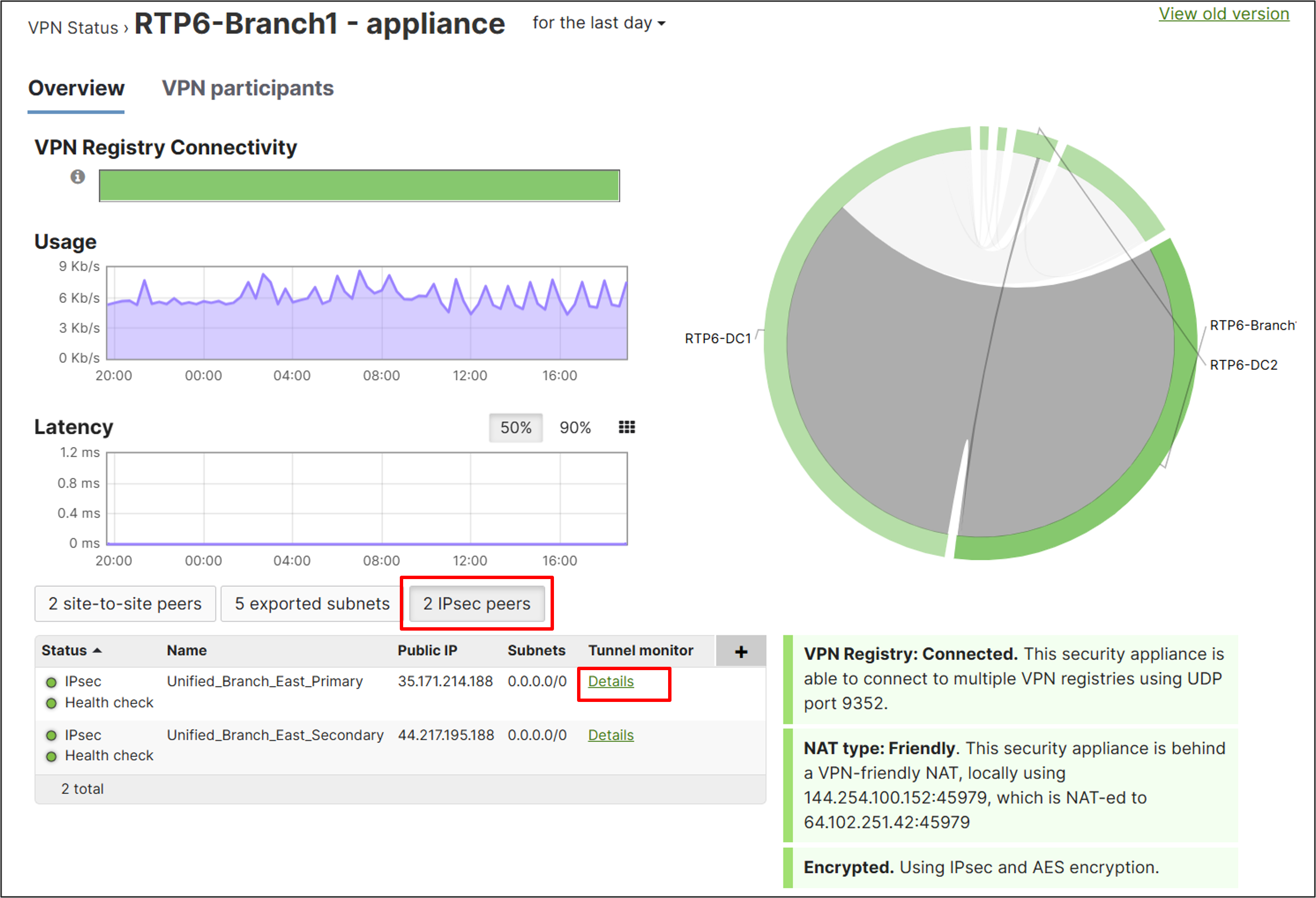
Step 4. For security events and incidents, go to Organization > Monitor > Security Center, where MX events and XDR incidents can be viewed.
For more information, refer to the Meraki Security Center documentation.
Appendix A: Hardware and software versions used
| Hardware |
Software |
| 2x MX85 |
MX 19.2.7 |
| 2x MS150-24P-4G stack |
MS 17.2.2 |
| 1x CW9172I |
MR 31.1.8 |
Appendix B: Example deployment settings
This appendix summarizes the configurations used in this example deployment. If a setting is not mentioned, the default has been taken. Some of the example values may use default values.
On the dashboard under Organization > Configure
| Main menu |
Section |
Subsection |
Values |
| Adaptive Policy |
Groups |
Name/SGT Value/Description
|
Finance_User_Group/10/Finance User Group Marketing_User_Group/20/Marketing User Group Finance_Server_Group/100/Finance Server Group Marketing_Server_Group/200/Marketing Server Group |
| Adaptive Policy |
Networks |
Networks/Enablement
|
RTP6-Branch2/Enabled RTP6-DC1/Enabled RTP6-DC2/Enabled |
| Adaptive Policy |
Policies |
Source/Dest/Permission |
Unknown/Finance_User_Group/Allow Unknown/Marketing_User_Group/Allow Unknown/Finance_Server_Group/Allow Unknown/Marketing_Server_Group/Allow Infrastructure/Finance_User_Group/Allow Infrastructure/Marketing_User_Group/Allow Infrastructure/Finance_Server_Group/Allow Infrastructure/Marketing_Server_Group/Allow Finance_User_Group/Finance_User_Group/Allow Finance_User_Group/Marketing_User_Group/Allow Finance_User_Group/Finance_Server_Group/Allow Finance_User_Group/Marketing_Server_Group/Deny Finance_User_Group/Unknown/Allow Finance_User_Group/Infrastructure/Allow Marketing_User_Group/Finance_User_Group/Allow Marketing_User_Group/Marketing_User_Group/Allow Marketing_User_Group/Marketing_Server_Group/Allow Marketing_User_Group/Finance_Server_Group/Deny Marketing_User_Group/Unknown/Allow Marketing_User_Group/Infrastructure/Allow Finance_Server_Group/Finance_User_Group/Allow Finance_Server_Group/Finance_Server_Group/Allow Finance_Server_Group/Unknown/Allow Finanace_Server_Group/Infrastructure/Allow Finance_Server_Group/Marketing_User_Group/Deny Finance_Server_Group/Marketing_Server_Group/Deny Marketing_Server_Group/Finance_User_Group/Deny Marketing_Server_Group/Finance_Server_Group/Deny Marketing_Server_Group/Marketing_User_Group/Allow Marketing_Server_Group/Marketing_Server_Group/Allow Marketing_Server_Group/Unknown/Allow Marketing_Server_Group/Infrastructure/Allow |
| Settings |
SNMP |
Version 2C Version 3 Authentication mode Authentication password Privacy mode Privacy password IP restrictions |
SNMP V2C disable SNMP V3 enabled SHA <passphrase> AES128 <passphrase> <IP address> |
| Policy Objects |
All objects |
Corp SNMP Corp DNS-DHCP Corp Mgt Corp RADIUS |
10.102.1.161 10.102.1.160 10.102.1.160 10.102.1.157 |
| Policy Objects |
All objects |
DATA Subnet Default Subnet GUEST Subnet INFRA Subnet IOT Subnet PCI Subnet VOICE Subnet |
10.10.0.0/16 192.168.128.0/24 172.16.99.0/24 10.250.0.0/16 10.30.0.0/16 10.40.0.0/16 10.20.0.0/16 |
| Policy Objects |
All objects |
Branch 2 Printer 1 Branch 2 Printer 2 |
10.30.2.101 10.30.2.102 |
| Policy Objects |
Groups |
Corp Shared Services Branch 2 Printers |
Corp DNS-DHCP, CORP RADIUS, Corp Mgt, Corp SNMP Branch 2 Printer 1, Branch 2 Printer 2 |
On the dashboard under Organization > Monitor
| Main Menu |
Section |
Subsection |
Values |
| Overview |
RTP6-Branch2 |
Tag |
SSE_East |
Network-side settings
On the dashboard under Network-wide > Configure
| Main menu |
Section |
Subsection |
Values |
| General |
General |
Network name |
RTP6-Branch2 |
| General |
General |
Local time zone |
America – New York (UTC -4.0, DST) |
| General |
Traffic analysis |
Traffic analysis |
Detailed: collect destination hostnames |
| General |
Device configuration |
Local credentials |
<Password> |
| General |
Reporting |
Syslog servers |
10.102.1.160, port 514, Appliance Event log, Appliance Security events, Switch Event log, Wireless Air Marshal events, Wireless Event log |
| General |
Reporting (SNMP Device Polling) |
SNMP access SNMP users Authentication Algorithm Privacy Mode |
V3 (username/passwords) Username: snmpuser/Passphrase: <passphrase> SHA AES128 |
| General |
Reporting |
Network traffic reporting NetFlow collector IP NetFlow collector port |
Enabled: send netflow traffic statistics 10.102.1.160 2055 |
| Alerts |
Alerts Settings |
Default recipients |
snmp |
| Alerts |
Alerts Settings |
Network-wide WAN appliance |
A rogue access point is detected Malware is downloaded |
| Alerts |
SNMP traps |
Access Users Receiving server IP Receiving server port |
V3 (username/password) Username: snmpuser, Passphrase: <passphrase> <IP address> 162 |
| Group policies |
DATA |
Adaptive Policy SGT |
Do not assign SGT |
| Group policies |
DATA |
Wireless only/VLAN |
Tag VLAN 10 |
| Group policies |
VOICE |
Adaptive Policy SGT |
Do not assign SGT |
| Group policies |
VOICE |
Wireless only/VLAN |
Tag VLAN 20 |
| Group policies |
IOT |
Adaptive Policy SGT |
Do not assign SGT |
| Group policies |
IOT |
Wireless only/VLAN |
Tag VLAN 30 |
| Group policies |
PCI |
Adaptive Policy SGT |
Do not assign SGT |
| Group policies |
PCI |
Wireless only/VLAN |
Tag VLAN 40 |
Cisco Secure Access settings
From the https://sse.cisco.com > Connect > Essentials > Network Connections > Network Tunnel Groups tab
| Main menu |
Section |
Subsection |
Values |
| Network Tunnel Groups |
General Settings |
Tunnel Group Name |
UnifiedBranchEast |
|
|
Tunnel ID and Passphrase |
Tunnel ID |
UnifiedBranchEast@<org><hub>.sse.cisco.com |
|
|
Routing |
Network Address Translation (NAT) |
Enable NAT/Outbound only |
MX router settings
On the dashboard under Security & SD-WAN > Monitor
| Main menu |
Section |
Subsection |
Values |
| Appliance Status |
Summary |
Appliance name (top left, edit mac address) |
B2-MX1 |
|
|
|
Address |
<Location> |
|
|
|
SPARE (edit) |
Uplink IPs: Use virtual uplink IPs WAN 1 shared IP (x.x.x.x) (unique IP address part of WAN 1 subnet) WAN 2 shared IP (x.x.x.x) (unique IP address part of WAN 2 subnet) |
| Spare Status |
Summary |
Appliance name (top left, edit mac address) |
B2-MX2 |
On the dashboard under Security & SD-WAN > Configure
| Main menu |
Section |
Subsection |
Values |
| Site-to-site VPN |
Site-to-site VPN |
Type |
Spoke |
| Site-to-site VPN |
Site-to-site VPN |
Hubs |
RTP6-DC1 RTP6-DC2 |
| Site-to-site VPN |
VPN settings |
Peer SGT capable |
Enabled |
| Site-to-site VPN |
Organization-wide settings |
IPsec Peers>Configure Health checks |
● Health check: SSE
● Endpoint: http://service.sig.umbrella.com
|
| Site-to-site VPN |
Organization-wide settings |
IPsec Peers>Add a Peer |
● Name: Unified_Branch_East_Primary
● IKE version: IKEv2
● Peers>Public IP or Hostname:
● Peers>Local ID:
● Peers>Shared secret:
● Peers>Routing: Static
● Peers>Private subnets: 0.0.0.0/0
● Peers>Availability: SSE_East
● Multi-Uplink IPsec VPN: Enable
● Tunnel monitoring>Health check: SSE
● IPsec policy>Preset: Umbrella
|
| Site-to-site VPN |
Organization-wide settings |
IPsec Peers>Unified_Branch _East_Primary>Add secondary peer |
● Inherit primary peer configurations
● Name: Unified_Branch_East_Secondary
● Peers>Public IP or Hostname:
● Peers>Local ID:
|
| Addressing & VLANs |
Deployment Settings |
Mode |
Routed |
| Addressing & VLANs |
Routing |
LAN Setting |
VLANs |
| Addressing & VLANs |
Routing |
Subnets |
● 999, INFRA, 10.250.2.1/24, VPN mode = Enabled
● 50, GUEST, 172.16.99.1/24, VPN mode = Disabled
● 40, PCI, 10.40.2.1/24, VPN mode = Enabled
● 30, IOT, 10.30.2.1/24, VPN mode = Enabled
● 20, VOICE, 10.20.2.1/24, VPN mode = Enabled
● 10, DATA, 10.10.2.1/24, VPN mode = Enabled
● 1, Default, 192.168.128.1/24, VPN mode = Disabled
|
| Addressing & VLANs |
Routing |
Per-port VLAN Settings |
● Ports 5 & 6 Enabled, Type Trunk, Native VLAN 1, Allowed VLANs = 1,10,20,30,40,50,999, Peer SGT Capable = Enabled, Adaptive Policy – 2: Infrastructure (Predefined)
● Ports 7-14 Disabled
|
| DHCP |
VLAN 1 (Default) |
Client addressing Mandatory DHCP DNS nameservers |
Run a DHCP server Enabled Use OpenDNS |
| DHCP |
VLAN 10 (DATA) |
Client addressing DHCP server IPs Mandatory DHCP |
Relay DHCP to another server 10.102.1.160 10.102.1.161 Disabled |
| DHCP |
VLAN 20 (VOICE) |
Client addressing DHCP server IPs Mandatory DHCP |
Relay DHCP to another server 10.102.1.160 10.102.1.161 Disabled |
| DHCP |
VLAN 30 (IOT) |
Client addressing DHCP server IPs Mandatory DHCP |
Relay DHCP to another server 10.102.1.160 10.102.1.161 Disabled |
| DHCP |
VLAN 40 (PCI) |
Client addressing DHCP server IPs Mandatory DHCP |
Relay DHCP to another server 10.102.1.160 10.102.1.161 Disabled |
| DHCP |
VLAN 50 (GUEST) |
Client addressing Mandatory DHCP DNS nameservers |
Run a DHCP server Enabled Use OpenDNS |
| DHCP |
VLAN 999 (INFRA) |
Client addressing Mandatory DHCP DNS nameservers Reserved IP ranges Custom nameservers Fixed IP assignments |
Run a DHCP server Disabled Specify nameservers <Any IOS XE switch stack Mgt IP addresses set manually> 10.102.1.160 10.102.1.161 B2-SW1, 6c:c3:b2:7f:a7:40, 10.250.2.11 B2-SW2, 5c:06:10:5f:67:2e, 10.250.2.12 B2-AP1, cc:6e:2a:d8:9b:10, 10.250.2.21 |
| Site-to-site VPN |
Organization-wide settings |
Site-to-site outbound firewall |
● Shared Services: Allow prot:Any Src:[DATA Subnet, IOT Subnet, VOICE Subnet, INFRA Subnet, PCI Subnet] Any Dest:Corp Shared Services Any
● Shared Services: Allow prot:Any Src:Corp Shared Services Any Dest:[DATA Subnet, IOT Subnet, VOICE Subnet, INFRA Subnet, PCI Subnet] Any
● Data Access: Deny prot:Any Src:DATA Subnet Any Dest:[IOT Subnet, VOICE Subnet, INFRA Subnet, PCI Subnet] Any
● IOT Access: Deny prot:Any Src:IOT Subnet Any Dest:[DATA Subnet, INFRA Subnet, VOICE Subnet, PCI Subnet] Any
● Infra Access: Deny prot:Any Src:INFRA Subnet Any Dest:[DATA Subnet, IOT Subnet, VOICE Subnet, PCI Subnet] Any
● Voice Access: Deny prot:Any Src:Voice Subnet Any Dest:[IOT Subnet, INFRA Subnet, DATA Subnet, PCI Subnet] Any
● PCI Access: Deny prot:Any Src:PCI Subnet Any Dest:[DATA Subnet, IOT Subnet, VOICE Subnet, INFRA Subnet] Any
● Default rule: Allow prot:Any Src:Any Any Dest:Any Any
|
| Firewall |
Layer 3 |
Outbound rules |
● Local Print Access: Allow prot:Any Src:[DATA Subnet] Any Dest:[Branch 2 Printers] Any
● Default (VLAN 1) Access: Deny prot:Any Src:Default Subnet Any Dest:[DATA Subnet, VOICE Subnet, IOT Subnet, PCI Subnet, GUEST Subnet, INFRA Subnet] Any
● Data Access: Deny prot:Any Src:DATA Subnet Any Dest:[Default Subnet, VOICE Subnet, IOT Subnet, PCI Subnet, GUEST Subnet, INFRA Subnet] Any
● IOT Access: Deny prot:Any Src:IOT Subnet Any Dest:[Default Subnet, DATA Subnet, VOICE Subnet, PCI Subnet, GUEST Subnet, INFRA Subnet] Any
● Infra Access: Deny prot:Any Src:INFRA Subnet Any Dest:[Default Subnet, DATA Subnet, VOICE Subnet, IOT Subnet, PCI Subnet, GUEST Subnet] Any
● Voice Access: Deny prot:Any Src:Voice Subnet Any Dest:[Default Subnet, DATA Subnet, IOT Subnet, PCI Subnet, GUEST Subnet, INFRA Subnet] Any
● PCI Access: Deny prot:Any Src:PCI Subnet Any Dest:[Default Subnet, DATA Subnet, VOICE Subnet, IOT Subnet, GUEST Subnet, INFRA Subnet] Any
● Guest Access: Deny prot:Any Src:GUEST Subnet Any Dest:[Default Subnet, DATA Subnet, VOICE Subnet, IOT Subnet, PCI Subnet, INFRA Subnet] Any
● Allow Direct Internet Access: Allow prot:Any Src:[INFRA Subnet, DATA Subnet, GUEST Subnet, Default Subnet] Any Dest:Any Any
● Deny All: Deny prot:Any Src:Any Any Dest: Any Any
● Default Rule: Allow prot:Any Src: Any Any Dest: Any Any
|
| Firewall |
Layer 3 |
WAN appliance services |
ICMP Any, Web None, SNMP None |
| SD-WAN & traffic shaping |
Uplink configuration |
WAN 1 |
400 Mbps |
| SD-WAN & traffic shaping |
Uplink configuration |
WAN 2 |
500 up/500 down |
| SD-WAN & traffic shaping |
Uplink selection |
Load balancing |
Disabled |
| SD-WAN & traffic shaping |
Uplink selection |
Multi-Uplink AutoVPN |
Enabled |
| SD-WAN & traffic shaping |
SD-WAN policies |
Custom performance classes |
● SaaS_Traffic, 150, 50, 5
● Critical_Apps, 150, 20. 2
● Default_SLA, (none), 100, 5
|
| SD-WAN & traffic shaping |
SD-WAN policies |
Internet traffic |
● Prefer WAN 2. Fail over if uplink down
● 10.250.0.0/24:any to any:any
|
| SD-WAN & traffic shaping |
SD-WAN policies |
Internet traffic |
● Prefer WAN 2. Fail over if poor performance for SaaS_Trafic
● 10.10.0.0/24 to Office 365 or Webex
|
| SD-WAN & traffic shaping |
SD-WAN policies |
VPN traffic |
● Prefer WAN 2. Fail over if poor performance for VoIP
● All VoIP & Video conferencing
|
| SD-WAN & traffic shaping |
SD-WAN policies |
VPN traffic |
● Prefer WAN 2. Fail over if poor performance for “Critical_Apps”
● TCP from Any to 10.102.1.161/32:443
|
| SD-WAN & traffic shaping |
SD-WAN policies |
VPN traffic |
● Prefer WAN 1. Fail over if poor performance for “Default_SLA”
● Any to Any
|
| SD-WAN & traffic shaping |
Local internet breakout |
VPN exclusion rules |
● Office 365 Suite
● Webex
● Layer 3 udp from Any to 64.62.142.12/32
● Layer 3 Any from Any to 158.115.128.0/19
● Layer 3 Any from Any to 209.206.48.0
● Layer 3 Any from Any to 216.157.128.0/20
|
| SD-WAN & traffic shaping |
Global bandwidth limits |
Per-client limit |
unlimited |
| SD-WAN & traffic shaping |
Traffic shaping rules |
Default Rules |
Enable default traffic shaping rules |
| SD-WAN & traffic shaping |
Traffic shaping rules |
Rule #1 |
● Definition: localnet 172.16.99.0/24
● Bandwidth limit: Ignore network per-client limit (unlimited)
● Priority: Low
● DSCP tagging: 0 (CS0/DF – Best Effort/Default Forwarding)
|
| SD-WAN & traffic shaping |
Traffic shaping rules |
Rule #2 |
● Definition: net/port 10.102.1.161/32
● Bandwidth limit: Ignore network per-client limit (unlimited)
● Priority: High
● DSCP tagging: 18 (AF21 – Low Latency Data, Low Drop)
|
| Threat Protection |
Advanced Malware Protection (AMP) |
Mode |
Enabled |
| Threat Protection |
Intrusion detection and prevention |
Mode Ruleset |
Prevention Balanced |
| Content Filtering |
Category blocking |
Content categories |
Adult, Hate Speech, Illegal Activities, Illegal Drugs, Pornography, Child Abuse Content, Illegal Downloads, Terrorism and Violent Extremism |
| Content Filtering |
Category blocking |
Threat categories |
Malware Sites, Spyware and Adware, Phishing, Botnets, Spam, Exploits, High Risk Sites and Locations, Bogon, Ebanking Fraud, Indicators of Compromise (IOC), Domain Generated Algorithm, Open HTTP Proxy, Open Mail Relay, TOR exit Nodes, Newly Seen Domains, Cryptojacking, Linkshare, Malicious Sites |
| Content Filtering |
URL filtering |
Blocked URL list |
www.example.com |
Switch settings
On the dashboard under Switching > Monitor
| Main menu |
Section |
Subsection |
Values |
| Switches (select one switch) |
Summary |
Switch name (top left, edit mac address) |
B2-SW1 |
|
|
|
Address |
<location> |
| Switches (select other switch) |
Summary |
Switch name (top left, edit mac address) |
B2-SW2 |
|
|
|
Address |
<location> |
| Switch Stacks (select stack) |
-- |
Stack name (top left, edit) |
B2-SW-STACK1 |
| Switch Ports (select all ports on switches which support less than 999 VLANs) (not needed in this example) |
Switch Ports |
All ports on switch |
Type: Trunk Allowed VLANs: 1,10,20,30,40,50,999 |
On the dashboard under Switching > Configure
| Main menu |
Section |
Subsection |
Values |
| Switch Settings |
Switch settings |
STP configuration |
Enable Rapid Spanning Tree (RSTP): Enabled STP bridge priority: Switches/Stacks (B2-SW-STACK1) STP bridge priority: Bridge priority (4096) |
| Switch Settings |
Switch settings |
Quality of service |
VLAN: 50, Trust: Disabled, Set DSCP: 0 (default) VLAN 10, Trust: Enabled VLAN 20, Trust: Enabled VLAN 30, Trust: Enabled VLAN 40, Trust: Enabled |
| Switch Settings |
Switch settings |
Storm control |
● Broadcast, 20%
● Multicast, 30%
● Unknown Unicast, 10%
|
| Access Policies |
Access Policies |
Name Authentication method RADIUS servers RADIUS servers RADIUS servers RADIUS server
Options |
Radius-MAB Radius server RADIUS Server testing RADIUS CoA support enabled Enable RADIUS accounting servers Host 10.102.1.157, secret <secret>, Auth enabled, Port 1812, Accounting enabled, Port 1813 Hybrid authentication, Multi-Auth, Both Voice auth enabled |
On the dashboard under Switching > Monitor
| Main menu |
Section |
Subsection |
Values |
| Switch Ports |
Switch Ports |
B2-SW1/1 B2-SW1/2 B2-SW2/1 B2-SW2/2 |
● Name: Uplink to Router
● Port status: Enabled
● Type: Trunk
● Access Policy: Open
● Native VLAN: 1
● Allowed VLANs: 1,10,20,30,40,50,999
● Peer SGT capable: Enabled
● Adaptive Policy group: 2: Infrastructure
● RSTP: Enabled
● STP guard: Disabled
● UDLD: Alert only
● PoE: Enabled
● Storm control: Enabled
|
| Switch Ports |
Switch Ports |
B2-SW1/3 B2-SW1/4 B2-SW1/5 |
● Name: INET1
● Port status: Enabled
● Type: Access
● Access Policy: Open
● VLAN: 901
● RSTP: Enabled
● STP guard: Disabled
● UDLD: Alert only
● PoE: Enabled
● Storm control: Enabled
|
| Switch Ports |
Switch Ports |
B2-SW2/3 B2-SW2/4 B2-SW2/5 |
● INET2
● Port status: Enabled
● Type: Access
● Access Policy: Open
● VLAN: 902
● RSTP: Enabled
● STP guard: Disabled
● UDLD: Alert only
● PoE: Enabled
● Storm control: Enabled
|
| Switch Ports |
Switch Ports |
B2-SW1/9 |
● Name: Link to AP
● Port status: Enabled
● Type: Trunk
● Access Policy: Open
● Native VLAN: 999
● Allowed VLANs: 1,10,20,30,40,50,999
● Peer SGT capable: Enabled
● Adaptive policy group: 2: Infrastructure
● RSTP: Enabled
● STP guard: BPDU guard
● UDLD: Alert only
● PoE: Enabled
● Storm control: Enabled
|
| Switch Ports |
Switch Ports |
B2-SW1/6-8 B2-SW1/10-12 B2-SW2/6-12 |
● Name: Disabled
● Port status: Disabled
|
| Switch Ports |
Switch Ports |
B2-SW1/13-28 B2-SW2/13-28 |
● Name: Access Port
● Port status: Enabled
● Type: Access
● Access Policy: RADIUS-MAB
● VLAN: 10
● VOICE VLAN: 20
● RSTP: Enabled
● STP guard: BPDU guard
● UDLD: Alert only
● PoE: Enabled
● Storm control: Enabled
|
On the dashboard under Switching > Configure
| Main menu |
Section |
Subsection |
Values |
| Switch Settings |
Switch settings |
VLAN configuration |
999 |
Access Point settings
On the dashboard under Wireless > Monitor
| Main menu |
Section |
Subsection |
Values |
| Access Points (select Access Point) |
Summary |
Access Point name (top left, edit mac address) |
B2-AP1 |
|
|
|
Address |
<Location> |
On the dashboard under Wireless > Configure
| Main menu |
Section |
Subsection |
Values |
| Access Control |
Basic info |
SSID (name) (Unconfigured SSID 1) |
BR2-GuestWiFi |
| Access Control |
Security (Guest) |
|
Open (no encryption) |
| Access Control |
Security (Guest) |
Mandatory DHCP |
Enabled |
| Access Control |
Splash page (Guest) |
|
Click-through |
| Access Control |
Client IP and VLAN (Guest) |
External DHCP server assigned |
Selected/Bridged |
| Access Control |
Client IP and VLAN (Guest) |
VLAN tagging |
VLAN ID: Default AP tag, VLAN ID 50 |
| Access Control>Splash page settings |
Splash page (Guest) |
Official themes |
Modern |
| Access Control>Splash page settings |
Customize your page (Guest) |
Welcome message |
Click to continue if you agree to the terms of usage of this guest service. |
| Access Control>Splash page settings
|
Splash behavior (Guest) |
Splash frequency Where should users go after the splash page? |
Every day The URL they were trying to fetch |
| Access Control |
Basic info |
SSID (name) (Unconfigured SSID 5) |
BR2-CorpWiFi |
| Access Control |
Security (Corp) |
|
Enterprise with my RADIUS server |
| Access Control |
Security (Corp) |
WPA encryption |
WPA3 Transition Mode |
| Access Control |
Security (Corp) |
802.11w |
Enabled (allow unsupported clients) |
| Access Control |
Security (Corp) |
Mandatory DHCP |
Enabled |
| Access Control |
Splash Page (Corp) |
|
None (direct access) |
| Access Control |
RADIUS (Corp) |
RADIUS servers |
10.102.1.157, 1812, <secret> |
| Access Control |
RADIUS (Corp) |
RADIUS accounting servers |
10.102.1.157, 1813, <secret> |
| Access Control |
RADIUS (Corp) |
RADIUS CoA support |
Disabled |
| Access Control |
RADIUS (Corp) |
RADIUS attribute specifying group policy name |
Filter-Id |
| Access Control |
Client IP and VLAN (Corp) |
External DHCP server assigned RADIUS override |
Selected/Bridged
|
| Access Control |
Client IP and VLAN (Corp) |
VLAN tagging |
VLAN ID: Default AP tag, VLAN ID 10 |
| Access Control |
Security (Corp) |
802.11r |
Enabled |
| Firewall & traffic shaping |
Block IPs and ports (Guest) |
Layer 2 LAN isolation |
Enabled |
| Firewall & traffic shaping |
Block IPs and ports (Guest) |
Outbound rules |
● Deny IPv4 Any Local LAN Any Wireless clients access LAN
● Allow IPV4 Any Any Any Default rule
|
| Firewall & traffic shaping |
Traffic shaping rules (Guest) |
Per-client bandwidth limit Enable SpeedBurst Per-SSID bandwidth limit Shape traffic Default Rules |
50 Mbps Enabled 100 Mbps Shape traffic on this SSID Enable default traffic shaping rules |
| Firewall & traffic shaping |
Block IPs and ports (Corp) |
Outbound rules |
● Allow IPv4 Any Local LAN Any Wireless clients access LAN
● Allow IPV4 Any Any Any Default rule
|
| Firewall & traffic shaping |
Traffic shaping rules (Corp) |
Per-client bandwidth limit Per-SSID bandwidth limit Shape traffic Default Rules |
Unlimited Unlimited Shape traffic on this SSID Enable default traffic shaping rules |
| SSID Availability |
SSID availability (all SSIDs) |
Visibility Per access point availability Scheduled availability Schedule templates |
Advertise this SSID publicly Enabled on all access points
Custom schedule (Sun/Sat unavailable, M-F available 7:00-19:00) |
| Radio Settings |
RRM |
AI-RRM |
Enable |
| Radio Settings |
RF profiles |
Basic Indoor Profile/Copy |
Medium Branch Profile |
| Radio Settings |
RF profiles (Small Branch Profile) |
General/Band selection |
Per SSID |
| Radio Settings |
RF profiles (Small Branch Profile) |
BR2-GuestWiFi BR2-CorpWiFi |
2.4/5 2.4/5/6/Band steering Enabled |
| Radio Settings |
Overview |
B2-AP1/Assign profile |
Medium Branch Profile |
On the dashboard under Security & SD-WAN > Configure
Note: For some MS switch stack models (such as the MS150, but not the MS390), there may be an issue moving all switch members into VLAN 999. If this is the case, configure Native VLAN 999 on the MX trunk port as a workaround. If this workaround is implemented, the switch trunks to the APs must be moved back to VLAN 1.
| Main menu |
Section |
Subsection |
Values |
| Addressing & VLANs |
Routing |
Per-port VLAN settings |
Port 5: Native VLAN 999 |
| Switch Ports |
Switch Ports |
B2-SW1/9 |
Native VLAN: 1 |
Appendix C: ISE Deployment Settings
This table documents the ISE deployment settings for the example deployment:
| Main menu |
Section |
Subsection |
Values |
| Administration |
Groups |
Endpoint Identity Groups |
● MAB-IOT_Devices
● MAB-VOICE_Devices
● MAB-PCI_Devices
|
| Administration |
Groups |
User Identity Groups |
● Employee
● Finance
● Marketing
● IOT
● Voice
● PCI
|
| Policy |
Policy Elements/Results |
Authorization Profiles/DATA_VLAN |
● Access Type = ACCESS_ACCEPT
● Tunnel-Private-Group-ID = 1:10
● Tunnel-Type = 1:13
● Tunnel-Medium-Type = 1:6
|
| Policy |
Policy Elements/Results |
Authorization Profiles/DATA-GP |
● Access Type = ACCESS_ACCEPT
● Filter-ID = DATA
|
| Policy |
Policy Elements/Results |
Authorization Profiles/Voice_VLAN |
● Access Type = ACCESS_ACCEPT
● Tunnel-Private-Group-ID = 1:20
● Tunnel-Type = 1:13
● Tunnel-Medium-Type = 1:6
● cisco-av-pair = device-traffic-class=voice
|
| Policy |
Policy Elements/Results |
Authorization Profiles/Voice-GP |
● Access Type = ACCESS_ACCEPT
● Filter-ID = VOICE
|
| Policy |
Policy Elements/Results |
Authorization Profiles/IOT_VLAN |
● Access Type = ACCESS_ACCEPT
● Tunnel-Private-Group-ID = 1:30
● Tunnel-Type = 1:13
● Tunnel-Medium-Type = 1:6
|
| Policy |
Policy Elements/Results |
Authorization Profiles/IOT-GP |
● Access Type = ACCESS_ACCEPT
● Filter-ID = IOT
|
| Policy |
Policy Elements/Results |
Authorization Profiles/PCI_VLAN |
● Access Type = ACCESS_ACCEPT
● Tunnel-Private-Group-ID = 1:40
● Tunnel-Type = 1:13
● Tunnel-Medium-Type = 1:6
|
| Policy |
Policy Elements/Results |
Authorization Profiles/PCI-GP |
● Access Type = ACCESS_ACCEPT
● Filter-ID = PCI
|
| Policy |
Policy Elements/Results |
Authorization Profiles/Finance_SGT |
● Access Type = ACCESS_ACCEPT
● cisco-av-pair = cts:security-group-tag=000A-0
|
| Policy |
Policy Elements/Results |
Authorization Profiles/Marketing_SGT |
● Access Type = ACCESS_ACCEPT
● cisco-av-pair = cts:security-group-tag=0014-0
|
| Policy |
Policy Sets (Wired Access) |
Conditions: Wired_802.1X or Wired_MAB |
● Authentication Policy:
◦ Wired_MAB (Internal Endpoints) ◦ Default (All_User_ID_Stores)
● Authorization Policy:
◦ IdentityGroup:Name = Endpoint Identity Groups:MAB-IOT_Devices or IdentityGroup:Name = User Identity Groups:IOT, Profile=IOT_VLAN ◦ IdentityGroup:Name = Endpoint Identity Groups:MAB-PCI_Devices or IdentityGroup:Name = User Identity Groups:PCI, Profile=PCI_VLAN ◦ IdentityGroup:Name = Endpoint Identity Groups:MAB-VOICE_Devices or IdentityGroup:Name = User Identity Groups:Voice, Profile=Voice_VLAN ◦ IdentityGroup:Name = Finance, Profile=DATA_VLAN, Finance_SGT ◦ IdentityGroup:Name = Marketing, Profile=DATA_VLAN, Marketing_SGT ◦ IdentityGroup:Name = Employee, Profile=DATA_VLAN |
| Policy |
Policy Sets (Wireless Access) |
Conditions: Wireless_802.1X |
● Authentication Policy:
◦ Default (All_User_ID_Stores)
● Authorization Policy:
◦ IdentityGroup:Name = User Identity Groups:IOT, Profile=IOT-GP ◦ IdentityGroup:Name = User Identity Groups:PCI, Profile=PCI-GP ◦ IdentityGroup:Name = User Identity Groups:Voice, Profile=Voice-GP ◦ IdentityGroup:Name = User Identity Groups:Finance, Profile=DATA-GP, Finance_SGT ◦ IdentityGroup:Name = User Identity Groups:Marketing, Profile=DATA-GP, Marketing_SGT ◦ IdentityGroup:Name = User Identity Groups:Employee, Profile=DATA-GP |
● Unified Branch Solution Brief
● Unified Branch Design Guide (CVD)
● Unified Branch Small Branch Deployment Guide (CVD)
● Unified Branch Large Branch Deployment Guide (CVD)
● Unified Branch Workflows Automation Toolkit
● Cisco Network as Code Website
● Branch as Code Github Repository
● From Fragmented to Future-ready with Unified Branch: Powering IT in the AI Era
● Cisco Unified Branch Product Page