Overview

Features

The Cisco Secure Firewall Management Center series includes three models: FMC1800, FMC2800, and FMC4800. The Firewall Management Center series runs software that provides extensive intelligence about the users, applications, devices, threats, and vulnerabilities that exist in your network. They also use this information to analyze your network’s vulnerabilities. They then provide tailored recommendations on what security policies to put in place and what security events you should investigate.

The Firewall Management Center series supports Cisco Secure Threat Defense Version 10.0.0. See the Cisco Secure Firewall Threat Defense Compatibility Guide, which provides Cisco Secure software and hardware compatibility, including operating system and hosting environment requirements, for each supported version.

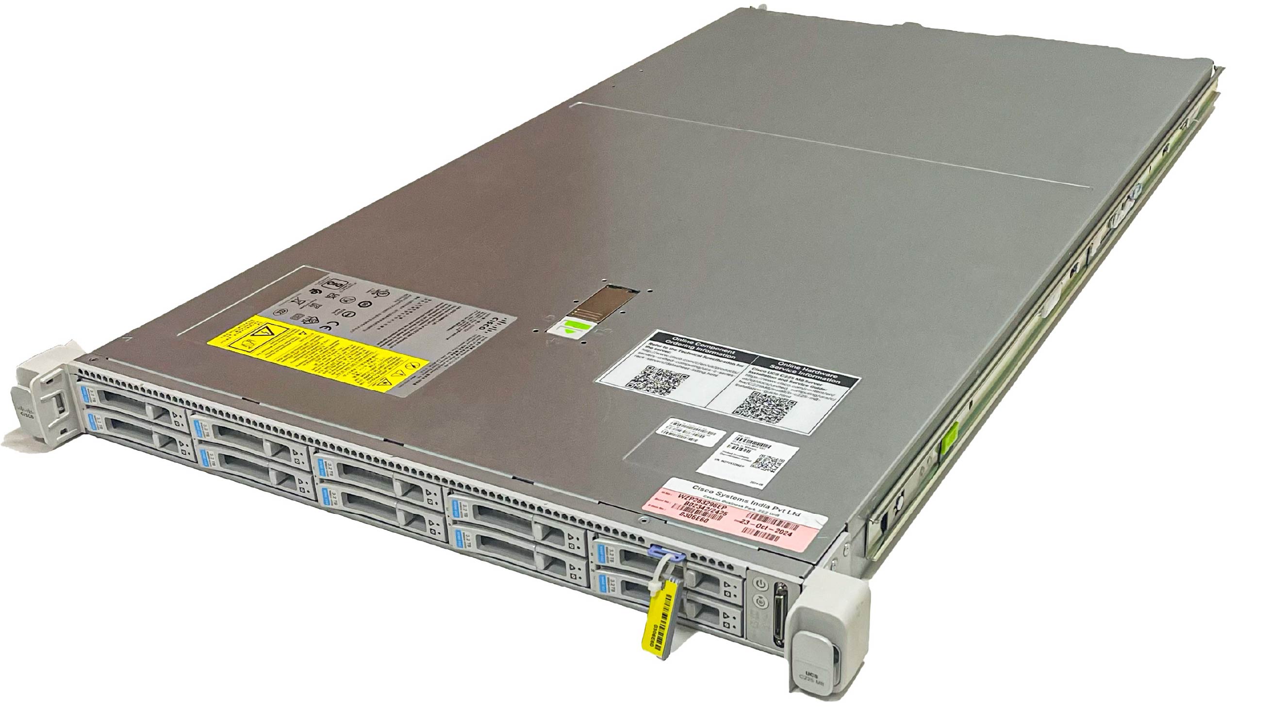
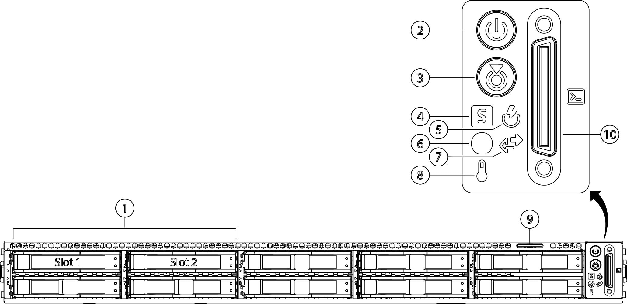
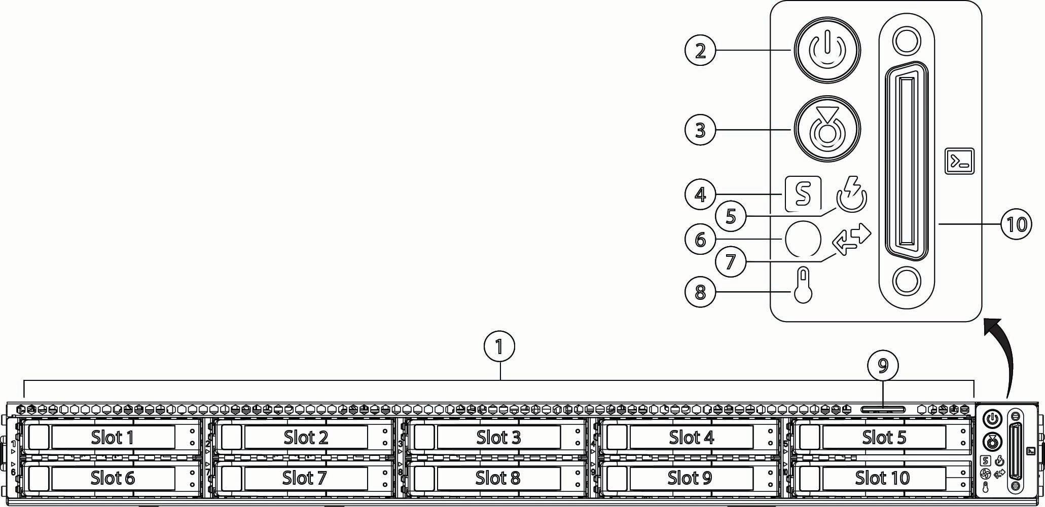
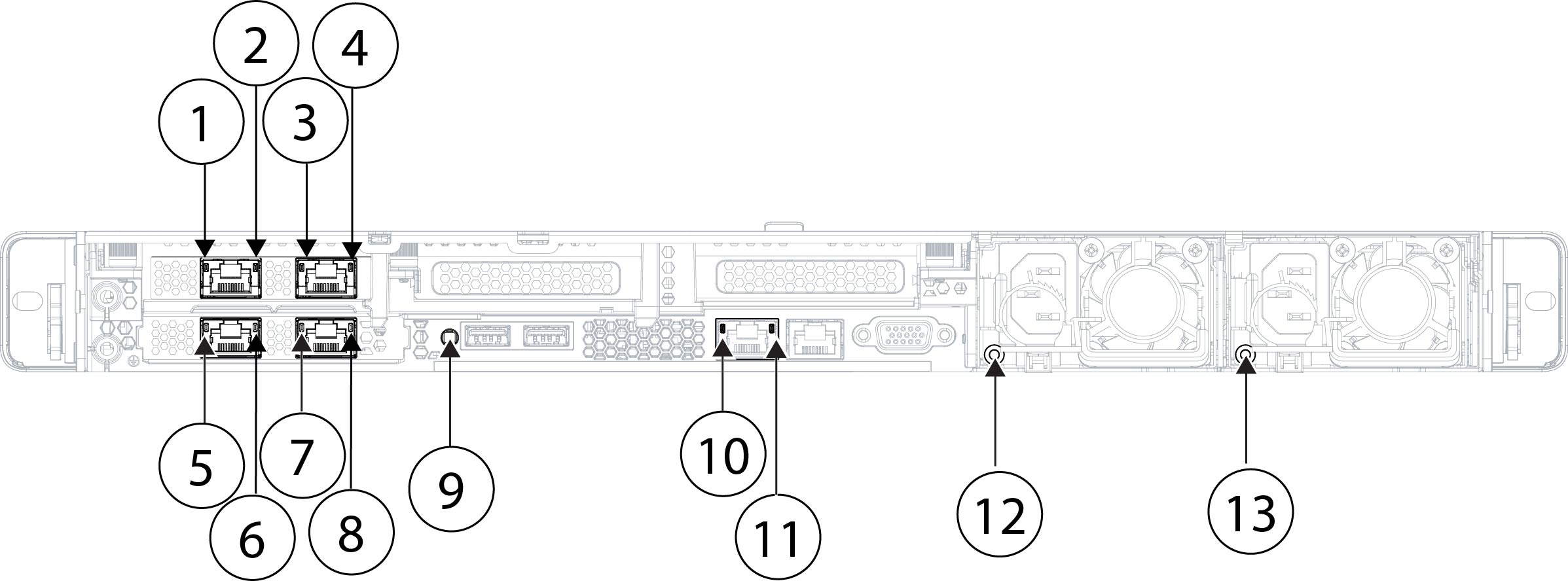
The following figure shows the FMC4800.

Figure 1. FMC4800
FMC4800

The following table lists the features of the Firewall Management Center series.

Table 1. FMC1800, FMC2800, and FMC4800 features

Feature

FMC1800

FMC2800

FMC4800

Form factor

1 RU

Rack mount

Standard 19-inch (48.3 cm) 4-post EIA rack

Airflow

Front to rear

Cold aisle to hot aisle
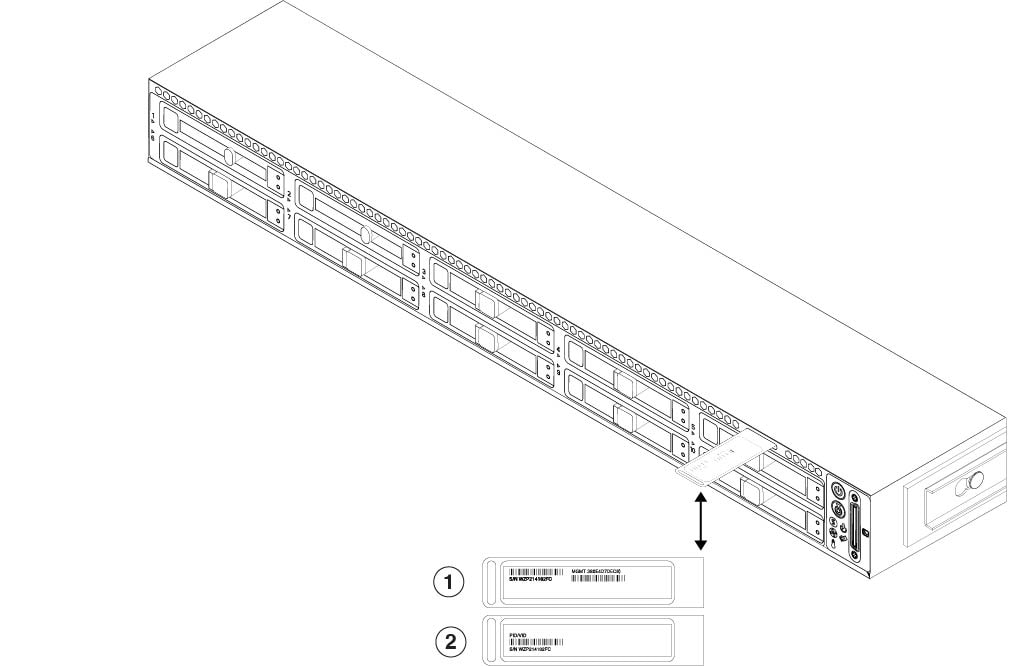
Pullout asset card

Displays the serial number and the MAC address for the two management ports (eth0 and eth1)
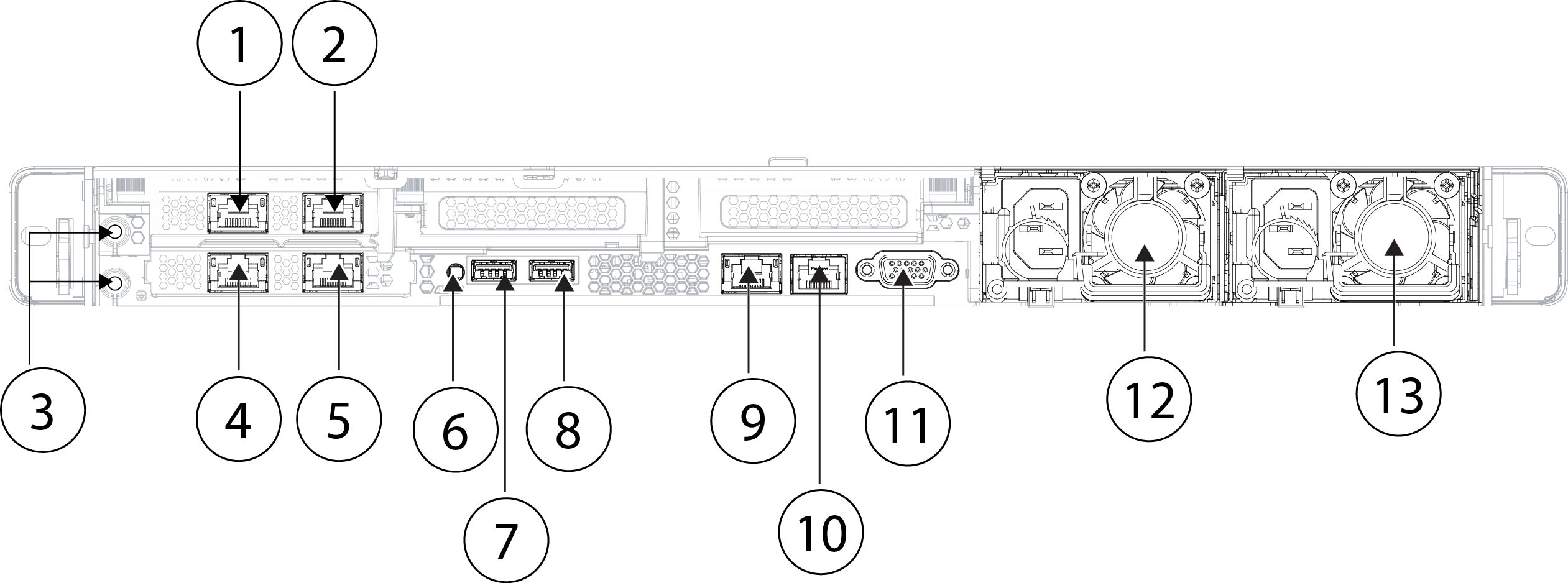
Grounding hole

Two threaded holes for a dual-hole grounding lug

Use is optional; the supported AC power supplies have internal grounding, so no additional chassis grounding is required.

Unit identification button

On the front panel

Power button

On the rear panel

System memory

64 GB

96 GB

384 GB

Cisco Integrated Management Controller (CIMC) port

One built-in 1-Gigabit Ethernet RJ-45 port

Support for 100/1000/10000 Mbps

Note


CIMC is supported only for Lights-Out Management (LOM) access. CIMC is not supported on any other interfaces.

Management ports

Two fixed 10-Gbps SFP+ ports (eth0 and eth1)

The primary management port is eth0. You can use eth1, eth2, and eth3 as secondary management or event ports.

Two fixed 10/25-Gbps SFP+ ports (eth0 and eth1)

The primary management port is eth0. You can use eth1, eth2, and eth3 as secondary management or event ports.

USB ports

Two USB 3.0 Type A

VGA port

One 3-row 15-pin DB-15 connector

Enabled by default

SFP ports

Two fixed 10-Gbps SFP+ ports (eth0 and eth1)

Two fixed 10/25-Gbps SFP+ ports (eth0 and eth1)

RJ-45 ports

Two built-in 10-Gigabit Ethernet RJ-45 (eth2 and eth3)

Support for 100/1000/10000 Mbps

Supported SFP+1

SFP-10G-SR (10 Gbps)

SFP-10G-LR (10 Gbps)

SFP-10G-SR (10 Gbps)

SFP-10G-LR (10 Gbps)

SFP-10G-SR (10 Gbps)

SFP-10G-LR (10 Gbps)

SFP-25G-SR-S (25 Gbps)

SFP-10/25G-LR-S (25 Gbps)

SFP-10/25G-CSR-S (25 Gbps)

Console port

RJ-45 serial port running RS-232 (RS-232D TIA-561)

System power

Two 1200-W AC power supplies

Hot-swappable and redundant as 1+1

Fans

Eight fans for front-to-rear cooling

Internal component only; not field-replaceable

Storage

Two 1.6-TB Nonvolatile Memory Express (NVMe) SSD slots

RAID 1, hot-swappable

Two 3.2-TB NVE SSD slots

RAID 1, hot-swappable

Ten 3.2-TB NVE SSD slots

RAID 10, hot-swappable

RAID controller

One

The chassis has a dedicated internal riser for a PCIe-style Cisco modular RAID controller card.

Internal component only; not field replaceable.

1 Use only SFPs that have been qualified for use on the management center. Although non-Cisco SFPs and other Cisco SFPs are allowed, we do not recommend using them because they have not been tested and validated by Cisco. Cisco TAC may refuse support for any interoperability problems that result from using an untested SFP transceiver.

Package contents

The following figure shows the package contents for the Firewall Management Center series. Note that the contents are subject to change and your exact contents might contain additional or fewer items.

Figure 2. FMC1800, FMC2800, and FMC4800 package contents
FMC1800, FMC2800, and FMC4800 package contents

1

Chassis

2

Cisco rail kit

3

Cisco Secure Firewall Management Center 1800, 2800, 4800

This document has links to the hardware installation guide, regulatory and safety information guide, and warranty and licensing information. It also contains a QR code and URL that point to the Digital Documentation Portal. The portal contains links to the product information page, the hardware installation guide, the regulatory and safety information guide, and the getting started guide.

4

Two 10-Gbps SFP+ transceivers with cables supported for all models or 25-Gbps SFP+ transceivers with cables supported for the FMC4800

Optional for all models; in package if ordered.

5

Power cord

See Power cord specifications for a list of approved power cords.

—

Serial number locations

The Serial Number (SN) and the Media Access Control (MAC) address for the chassis are printed on the top of the pullout asset card located on the front panel as shown in the following figure. The PID (Product ID) and VID (Version ID) are printed on the back of the pullout asset card.

Figure 3. Serial number location on pullout asset card
Serial number location on pullout asset card

1

Front of the pullout asset tag with the SN and MAC address

2

Bottom of the pullout asset tag with the PID and VID numbers

The serial number is also on the label on the cover of the chassis as shown in the following figure.


Caution


The cover latch on the top of the chassis cover is not supported. There are no internal field-replaceable parts in the chassis.


Figure 4. Serial number and documentation portal location on the cover
Serial number and documentation portal location on the cover

1

Chassis compliance labels with the SN, MAC address, etc. and a QR code that points to the Documentation Portal

Note


Scan the QR code to go to the Documentation Portal, which has links to the product page, hardware installation guide, the regulatory and compliance guide, and the getting started guide.

2

Cover latch

Not supported

Front panel

The following figure shows the front panel features and disk-drive configuration for the FMC1800 and the FMC2800. See Front panel LEDs for a description of the LEDs.

Figure 5. FMC1800 and FCS2800 front panel
FMC1800 and FCS2800 front panel

1

Drive bays

Supports two NVMe SSDs in slots 1 and 2

2

Power button/power status LED

3

Unit identification button/LED

4

System status LED

5

Power supply status LED

6

Fan status LED

7

Network link activity LED

8

Temperature status LED

9

Pullout asset card

10

Keyboard, video, and mouse (KVM) port

Not supported; use the VGA and USB keyboard ports instead.

The following figure shows the front panel features and disk-drive configuration for the FMC4800. See Front panel LEDs for a description of the LEDs.

Figure 6. FMC4800 front panel
FMC4800 front panel

1

Drive bays

Supports ten NVMe SSDs in slots 1 through 10

2

Power button/power status LED

3

Unit identification button/LED

4

System status LED

5

Power supply status LED

6

Fan status LED

7

Network link activity LED

8

Temperature status LED

9

Pullout asset card

10

KVM port

Not supported; use the VGA and USB keyboard ports instead.

Front panel LEDs

The following figure shows the front panel LEDs of the Firewall Management Center series and describes their states.

Figure 7. FMC1800, FMC2800, and FMC4800 front panel LEDs
FMC1800, FMC2800, and FMC4800 front panel LEDs

1

Drive fault LED:

  • Off—The drive is operating properly.

  • Amber—Drive fault detected.

  • Amber, flashing—The drive is rebuilding.

  • Amber, flashing with 1-second interval—Drive locate function activated in the software.

2

Drive activity LED:

  • Off—There is no drive in the drive tray (no access, no fault).

  • Green—The drive is ready.

  • Green, flashing—The drive is reading or writing data.

3

Power LED:

  • Off—There is no AC power to the chassis.

  • Amber—The chassis is in standby mode.

  • Green—The chassis is in main power mode. Power is supplied to all components.

4

Unit identification LED:

  • Off—The unit identification function is not in use.

  • Blue, flashing—The unit identification function is activated.

5

System status LED:

  • Green—The chassis is running in normal operating condition.

  • Green, flashing—The chassis is performing system initialization and memory check.

  • Amber—The chassis is in a degraded operational state (minor fault).

    • Power supply redundancy is lost.

    • CPUs are mismatched.

    • At least one CPU is faulty.

    • At least one DIMM is faulty.

    • At least one drive in a RAID configuration failed.

  • Amber, two flashes—There is a major fault with the system board.

  • Amber, three flashes—There is a major fault with the DIMMs.

  • Amber, four flashes—There is a major fault with the CPUs.

6

Power supply status LED:

  • Green—All power supplies are operating normally.

  • Amber—One or more power supplies are in a degraded operational state.

  • Amber, flashing—One or more power supplies are in a critical fault state.

7

Fan status LED:

  • Green—All fans are operating properly.

  • Amber, flashing—One or more fans breached the unrecoverable threshold.

8

Network link activity LED:

  • Off—The Ethernet port link is idle.

  • Green—One or more Ethernet ports are link-active, but there is no activity.

  • Green, flashing—One or more Ethernet ports are link-active with activity.

9

Temperature status LED:

  • Green—The chassis is operating at normal temperature.

  • Amber—One or more temperature sensors breached the critical threshold.

  • Amber, flashing—One or more temperature sensors breached the unrecoverable threshold.

—

Rear panel


Note


The CIMC is only supported for LOM access on the CIMC port (labeled M) on a Serial Over LAN (SOL) connection to remotely monitor or manage the management center system. For information on using LOM and SOL, see the "Set Up Lights Out Management" section in the Getting Started Guide.


Note


See Features for the list of qualified SFPs.


The following figure shows the rear panel of the Firewall Management Center series.

Figure 8. FMC1800, FMC2800, and FMC4800 rear panel
FMC1800, FMC2800, and FMC4800 rear panel

1

eth1 management interface (SFP)

10-Gbps SFP+ (FMC1800 and FMC2800)

10/25-Gbps SFP+ (FMC4800 )

Use as a secondary management port or event port

2

eth0 management interface (SFP)

Default primary management port

10-Gbps SFP+ (FMC1800 and FMC2800)

10/25-Gbps SFP+ (FMC4800 )

3

Threaded holes for dual-hole grounding lug

4

eth2 management interface (RJ-45)

Supports 100/1000/10000 Mbps depending on link partner capability.

Use as a secondary management port or event port.

5

eth3 management interface (RJ-45)

Supports 100/1000/10000 Mbps depending on link partner capability.

Use as a secondary management port or event port.

6

Unit identification button

7

USB 3.0 Type A (USB 1)

You can connect a keyboard, and along with a monitor on the VGA port, you can access the console.

8

USB 3.0 Type A (USB 2)

You can connect a keyboard, and along with a monitor on the VGA port, you can access the console.

9

CIMC interface (labeled M)

Note


CIMC is supported only for LOM access. CIMC is not supported on any other interfaces.

10

Serial console port (RJ-45 connector)

Disabled by default; use the VGA port and keyboard USB port instead.

11

VGA video port (DB-15 connector)

12

1200-W AC power supply (PSU 1)

13

1200-W AC power supply (PSU 2)

14

—

Rear panel LEDs

The following figure shows the rear panel LEDs and describes their states.

Figure 9. FMC1800, FMC2800, and FMC4800 rear panel LEDs
FMC1800, FMC2800, and FMC4800 rear panel LEDs

100-Mbps/1-Gbps/10-Gbps SFP Ethernet port (eth1) link status:

  • Off—No link is present.

  • Green—Link is active.

  • Green, flashing—Traffic is present on the active link.

100-Mbps/1-Gbps/10-Gbps SFP Ethernet port (eth1) link speed:

  • Off—Link speed is 100 Mbps.

  • Amber—Link speed is 1 Gbps.

  • Green—Link speed is 10 Gbps.

100-Mbps/1-Gbps/10-Gbps SFP Ethernet port (eth0) link status:

  • Off—No link is present.

  • Green—Link is active.

  • Green, flashing—Traffic is present on the active link.

100-Mbps/1-Gbps/10-Gbps SFP Ethernet port (eth0) link speed:

  • Off—Link speed is 100 Mbps.

  • Amber—Link speed is 1 Gbps.

  • Green—Link speed is 10 Gbps.

1

100-Mbps/1-Gbps/10-Gbps RJ-45 Ethernet port (eth2) link status:

  • Off—No link is present.

  • Green—Link is active.

  • Green, flashing—Traffic is present on the active link.

2

100-Mbps/1-Gbps/10-Gbps RJ-45 Ethernet port (eth2) link speed:

  • Off—Link speed is 100 Mbps.

  • Amber—Link speed is 1 Gbps.

  • Green—Link speed is 10 Gbps.

3

100-Mbps/1-Gbps/10-Gbps RJ-45 Ethernet port (eth3) link status:

  • Off—No link is present.

  • Green—Link is active.

  • Green, flashing—Traffic is present on the active link.

4

100-Mbps/1-Gbps/10-Gbps RJ-45 Ethernet port (eth3) link speed:

  • Off—Link speed is 100 Mbps.

  • Amber—Link speed is 1 Gbps.

  • Green—Link speed is 10 Gbps.

9

Unit identification:

  • Off—The unit identification function is not in use.

  • Blue, flashing—The unit identification function is activated.

10

1-Gbps Ethernet dedicated management port (CIMC) link status:

  • Off—No link is present.

  • Green—Link is active.

  • Green, flashing—Traffic is present on the active link.

11

1-Gbps Ethernet dedicated management port (CIMC) link speed:

  • Off—Link speed is 10 Mbps.

  • Amber—Link speed is 100 Gbps.

  • Green—Link speed is 1 Gbps.

12

Power supply 1 (one LED for each power supply):

  • Off—No AC input (12-V main power off; 12-V standby power off)

  • Green, flashing—12-V main power off; 12-V standby power on.

  • Green—12-V main power on; 12-V standby power on.

  • Amber, flashing—Warning threshold detected but 12-V main power on.

  • Amber—Critical error detected; 12-V main power off (for example, overcurrent, overvoltage, or overtemperature failure).

13

Power supply 2 (one LED for each power supply):

  • Off—No AC input (12-V main power off; 12-V standby power off)

  • Green, flashing—12-V main power off; 12-V standby power on.

  • Green—12-V main power on; 12-V standby power on.

  • Amber, flashing—Warning threshold detected but 12-V main power on.

  • Amber—Critical error detected; 12-V main power off (for example, overcurrent, overvoltage, or overtemperature failure).

—

Power supply

The following table lists the specifications for each 1200-W AC power supply used in the Firewall Management Center series.

Table 2. FMC1800, FMC2800, FMC4800 power supply specifications

Description

Specification

Input voltage range

100 to 230 VAC

Input frequency range

50–60 Hz

Maximum input current

12.97 A at 100 VAC

Maximum input volt amperes

1345 VA at 208 VAC

Maximum inrush current

20 A

Maximum hold-up time

12 ms at 1200 W

Maximum output power per power supply

1200 W

Power supply output voltage

12 VDC

Power supply standby voltage

12 VDC

Efficiency rating

Climate Savers Platinum Efficiency (80 Plus Titanium certified)

Form factor

RSP2

Input connector

IEC320 C13/C15

Hardware specifications

The following table lists the hardware specifications for the Firewall Management Center series.

Table 3. FMC1800, FMC2800, and FMC4800 hardware specifications

Specification

FMC1800

FMC2800

FMC4800

Dimensions (H x W x D)

1.7 x 16.9 x 30 inches (4.3 x 42.9 x 76.2 cm)

Weight

32.2 lb (16.6 kg)

34.1 lb (16.8 kg)

36.0 lb (17.0 kg)

Temperature

Operating: 50 to 95°F (10 to 35°C)

Maximum temperature is derated by 1°F/547 ft (1°C/300 m) of altitude above 3117 ft (950 m).

Nonoperating: –40 to 149°F (–40 to 65°C)

When the appliance is stored or transported.

Relative humidity

Operating: 8 to 90% noncondensing

Nonoperating: 5 to 95% noncondensing

Altitude

Operating: 0 to 10,000 ft

Nonoperating: 0 to 40,000 ft when the appliance is stored or transported

Sound power level

5.8 Bels (measure A-weighted per ISO7779 LWAd)

Operation at 73°F (23°C)

Sound pressure level

43 dBa (measure A-weighted per ISO7779 LpAM)

Operation at 73°F (23°C)

Product ID numbers

The following table lists the field-replaceable PIDs associated with the Firewall Management Center series. The spare components are ones that you can order and replace yourself. If any internal components fail, you must get a return material authorization (RMA) for the entire chassis including the SFPs and SFP cables. Remove the drives and power supplies before you send the chassis for RMA. See the Cisco Returns Portal for more information.

Table 4. FMC1800, FMC2800, and FMC4800 PIDs

PID

Description

FMC1800-K9

Cisco Secure Firewall Management Center 1800

FMC2800-K9

Cisco Secure Firewall Management Center 2800

FMC4800-K9

Cisco Secure Firewall Management Center 4800

FMC-M8-PWR-AC-1200

AC power supply

UCSC-PSU1-1200W-D=

AC power supply (spare)

FMC-M8-NVME1600

FMC1800 1.6-TB drive

UCS-NVMEG4-M1600=

FMC1800 1.6-TB drive (spare)

FMC-M8-NVME3200

FMC2800 and FMC4800 3.2-TB drive

UCS-NVMEG4-M3200=

FMC2800 and FMC4800 3.2-TB drive (spare)

UCSC-RAIL-M6

Rail kit

UCSC-RAIL-M6=

Rail kit (spare)

Power cord specifications

Each power supply has a separate power cord. Standard power cords or jumper power cords are available for connection to the Firewall Management Center series. The jumper power cords for use in racks are available as an optional alternative to the standard power cords.

If you do not order the optional power cord with the system, you are responsible for selecting the appropriate power cord for the product. Using a incompatible power cord with this product may result in electrical safety hazard. Orders delivered to Argentina, Brazil, and Japan must have the appropriate power cord ordered with the system.


Note


Only the approved power cords and jumper cords provided with the Firewall Management Center series are supported.


The following power cords and jumper cords are supported.

Figure 10. Argentina (CAB-250V-10A-AR)
Argentina (CAB-250V-10A-AR)

1

Plug: IRAM 2073

2

Cord set rating: 10 A, 250 V

3

Connector: IEC 60320/C13

Length: 8.2 ft (2.5 m)

Figure 11. Australia (CAB-9K10A-AU)
Australia (CAB-9K10A-AU)

1

Plug: A.S. 3112-2000

2

Cord set rating: 10 A, 250 V

3

Connector: IEC 60320/C15

Length: 8.2 ft (2.5 m)

Figure 12. Brazil (PWR-250V-10A-BZ)
Brazil (PWR-250V-10A-BZ)

1

Plug: NBR 14136

2

Cord set rating: 10 A, 250 V

3

Connector: IEC 60320/C13

Length: 8.2 ft (2.5 m)

Figure 13. Cabinet jumper (CAB-C13-C14-2M)
Cabinet jumper (CAB-C13-C14-2M)

1

Plug: SS10A

2

Cord set rating: 10A, 250V

3

Connector: HS10S, C-13 to C-14

Length: 6.6 ft (2.0 m)

Figure 14. Cabinet jumper (CAB-C13-C14-AC)
Cabinet jumper (CAB-C13-C14-AC)

1

Plug: SS10A

2

Cord set rating: 10 A, 250 V

3

Connector: HS10S, C-13 to C-14 (recessed receptacle)

Length: 9.8 ft (3.0 m)

Figure 15. Cabinet jumper (CAB-C13-CBN)
Cabinet jumper (CAB-C13-CBN)

1

Plug: SS10A

2

Cord set rating: 10 A, 250 V

3

Connector: HS10S, C-13 to C-14

Length: 2.2 ft (.68 m)

Figure 16. China (CAB-250V-10A-CH)
China (CAB-250V-10A-CH)

1

Plug: GB2099.1/2008

2

Cord set rating: 10 A, 250 V

3

Connector: IEC 60320/C13

Length: 8.2 ft (2.5 m)

Figure 17. Europe (CAB-9K10A-EU)
Europe (CAB-9K10A-EU)

1

Plug: CEE 7/7 (M2511)

2

Cord set rating: 10 A, 250 V

3

Connector: IEC 60320/C15 (VSCC 15)

Length: 8.2 ft (2.5 m)

Figure 18. India (CAB-250V-10A-ID)
India (CAB-250V-10A-ID)

1

Plug: IS 6538-1971

2

Cord set rating: 10 A, 250 V

3

Connector: IEC 60320-C13

Length: 8.2 ft (2.5 m)

Figure 19. Israel (CAB-250V-10A-IS)
Israel (CAB-250V-10A-IS)

1

Plug: SI-32

2

Cord set rating: 10 A, 250 V

3

Connector: IEC 60320-C13

Length: 8.2 ft (2.5 m)

Figure 20. Italy (CAB-9K10A-IT)
Italy (CAB-9K10A-IT)

1

Plug: CEI 23-16/VII (I/3G)

2

Cord set rating: 10 A, 250 V

3

Connector: IEC 60320/C15

(EN 60320/C15M)

Length: 8.2 ft (2.5 m)

Figure 21. Japan (CAB-C13-C14-2M-JP)
Japan (CAB-C13-C14-2M-JP)

1

Plug: EN 60320-2-2/E

2

Cord set rating: 10 A, 250 V

3

Connector: EN 60320/C13 to C14

Length: 6.6 ft (2.0 m)

Figure 22. North America (CAB-9K12A-NA)
North America (CAB-9K12A-NA)

1

Plug: NEMA5-15P

2

Cord set rating: 13 A, 125 V

3

Connector: IEC 60320/C15

Length: 8.2 ft (2.5 m)

Figure 23. North America (CAB-N5K6A-NA)
North America (CAB-N5K6A-NA)

1

Plug: NEMA6-15P

2

Cord set rating: 6 A, 200/240 V

3

Connector: IEC 60320/C13

Length: 8.2 ft (2.5 m)

Figure 24. North America (CAB-AC-L620-C13)
North America (CAB-AC-L620-C13)

1

Plug: NEMA L6-20 (molded twist lock)

2

Cord set rating: 13 A, 125 V

3

Connector: IEC 60320/C13

Length: 6.6 ft (2.0 m)

Figure 25. Switzerland (CAB-9K10A-SW)
Switzerland (CAB-9K10A-SW)

1

Plug: SEV 1011 (MP232-R)

2

Cord set rating: 10 A, 250 V

3

Connector: IEC 60320/C15

Length: 8.2 ft (2.5 m)

Figure 26. Taiwan (CAB-ACTW)
Taiwan (CAB-ACTW)

1

Plug: EL 302 (CNS10917)

2

Cord set rating: 10 A, 250 V

3

Connector: IEC 60320/C13

Length: 7.5 ft (2.3 m)

Figure 27. United Kingdom (CAB-9K10A-UK)
United Kingdom (CAB-9K10A-UK)

1

Plug: BS1363A/SS145

2

Cord set rating: 10 A, 250 V

3

Connector: IEC 60320/C15

Length: 8.2 ft (2.5 m)