Features
The Cisco Secure Firewall 6100 series is a standalone modular security services platform that includes the 6160 and 6170. They support Cisco Secure Firewall Threat Defense Version 10.0.0 and Cisco Secure ASA Version 9.24.1 software
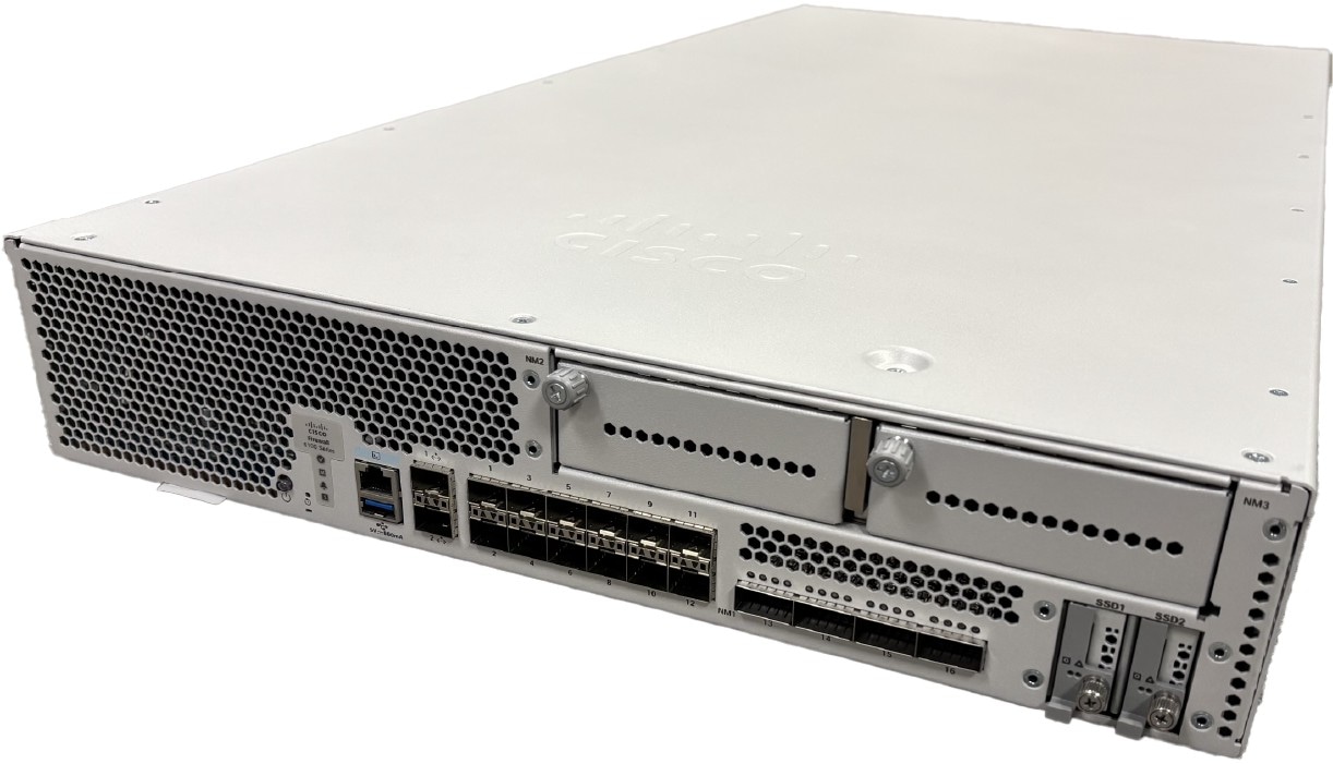
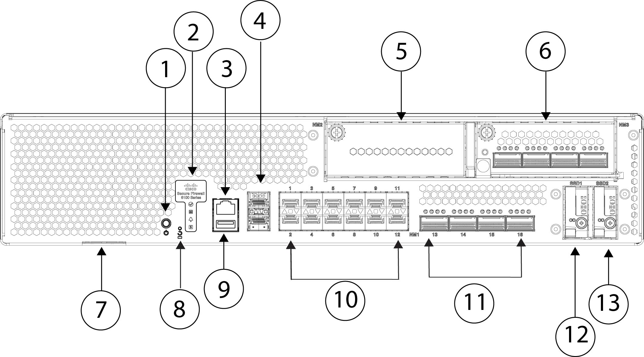
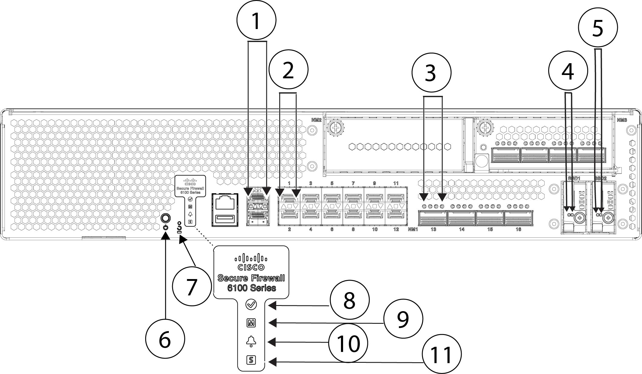
The following figure shows the Secure Firewall 6100 series chassis.
The following table lists the features for the Secure Firewall 6100 series.
|
Feature |
CSF-6160 |
CSF-6170 |
||
|---|---|---|---|---|
|
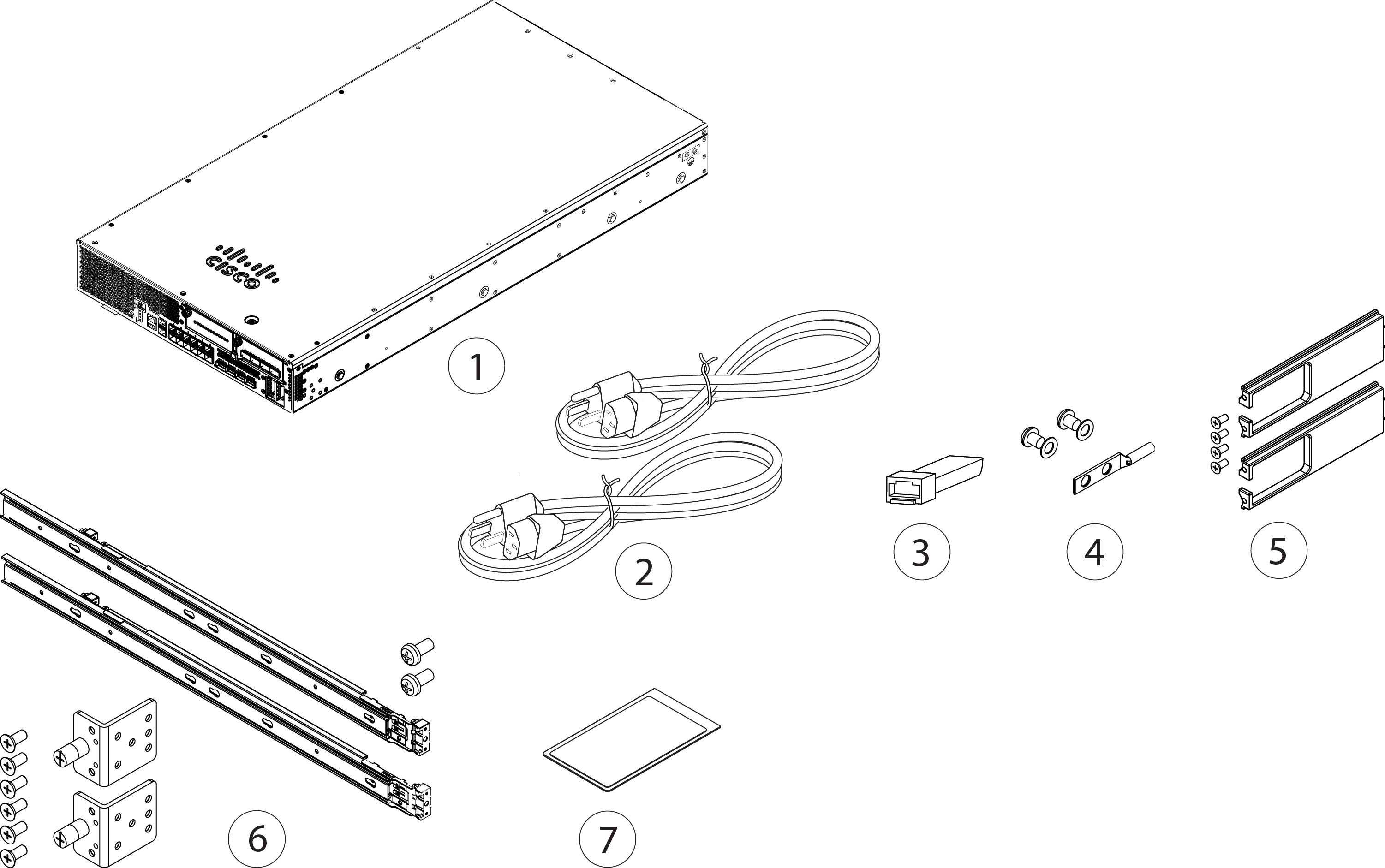
Form factor |
2 RU Fits a standard 19-inch (48.3-cm) rack |
|||
|
Mounting |
Two slide-rail mounting brackets and two slide rails 4-post Electronic Industries Association (EIA)-310-D rack |
|||
|
Airflow |
Front to rear (I/O side to non-I/O side) Cold aisle to hot aisle |
|||
|
System memory |
24 x 64 GB |
24 x 96 GB |
||
|
Management ports |
Two 1/10/25-Gbps SFP28 ports |
|||
|
Console port |
One Cisco Serial (RS-232 on RJ-45) |
|||
|
USB port |
One USB 3.0 with a 5-W Type A port |
|||
|
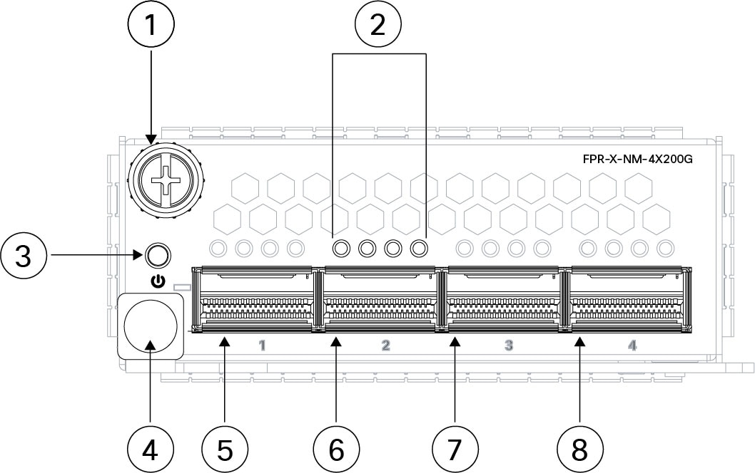
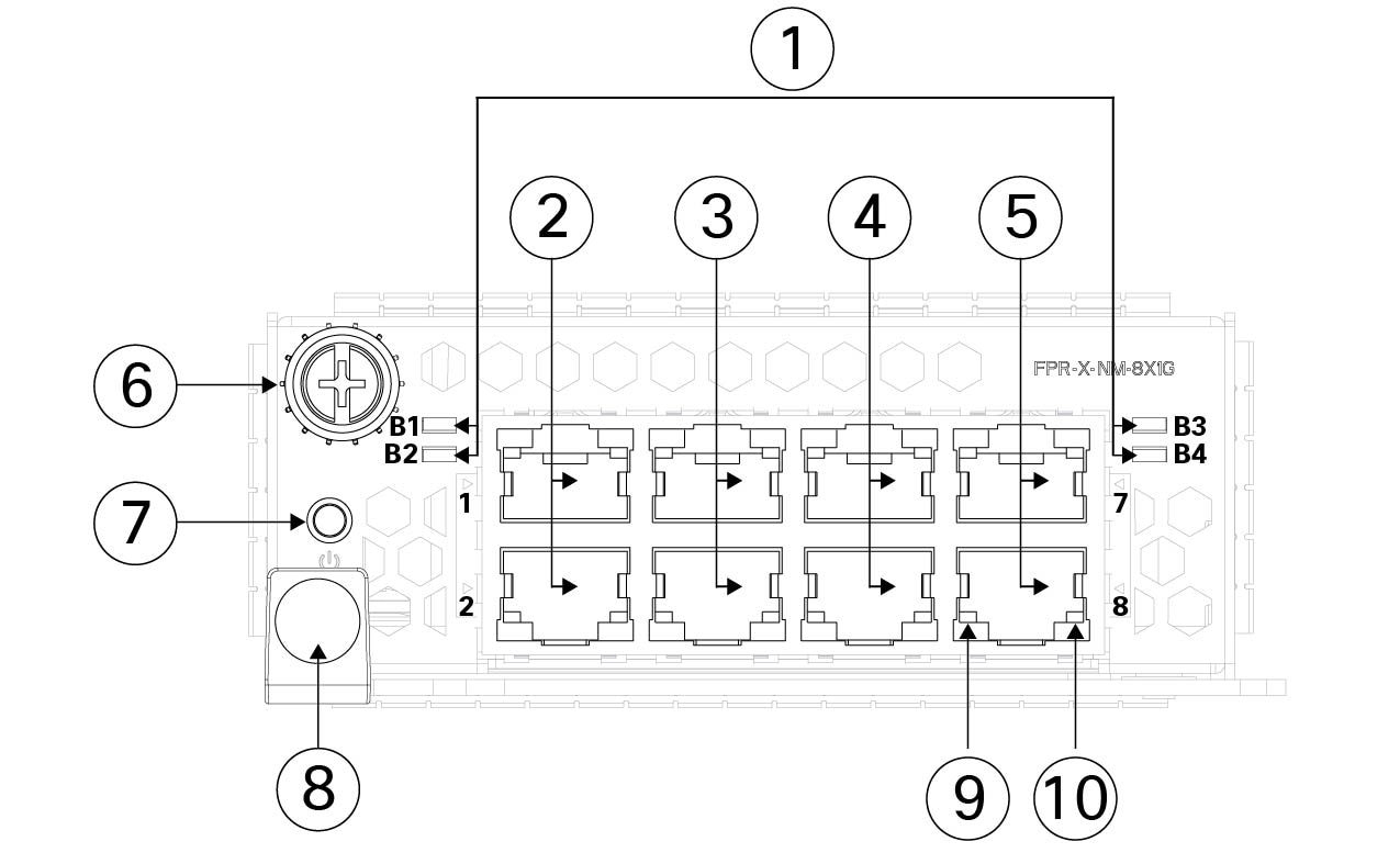
Network ports |
Twelve fixed 1/10/25/50-Gbps SFP56 fiber ports (named Ethernet 1/1 through 1/12) Four fixed 4x40/100/200 QSFP56 ports (named Ethernet 1/13 to 1/16) |
|||
|
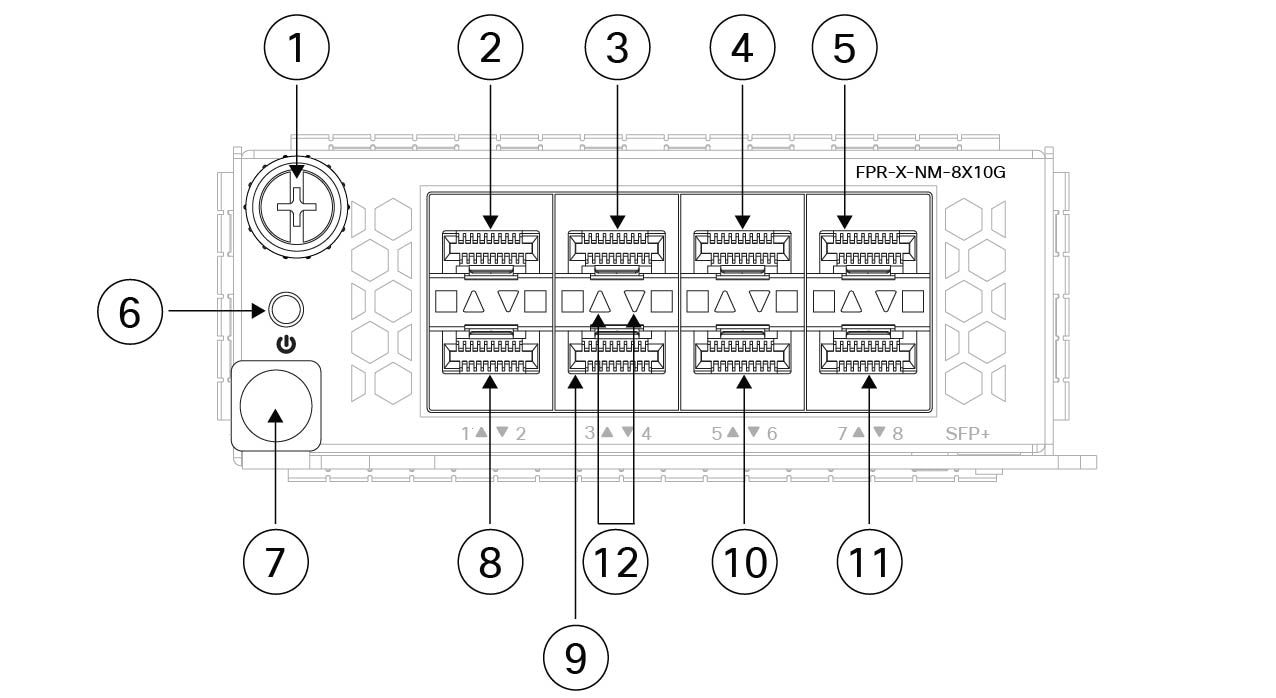
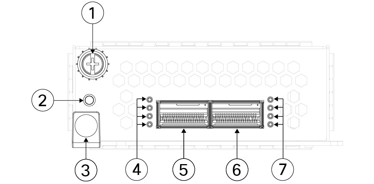
Network modules |
Two (hot-swappable)
|
|||
|
Supported network modules |
See Management, console, USB, and network ports for a list of supported network modules. |
|||
|
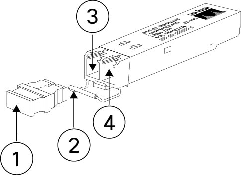
Supported SFPs |
See Supported transceivers for a list of supported SFPs. |
|||
|
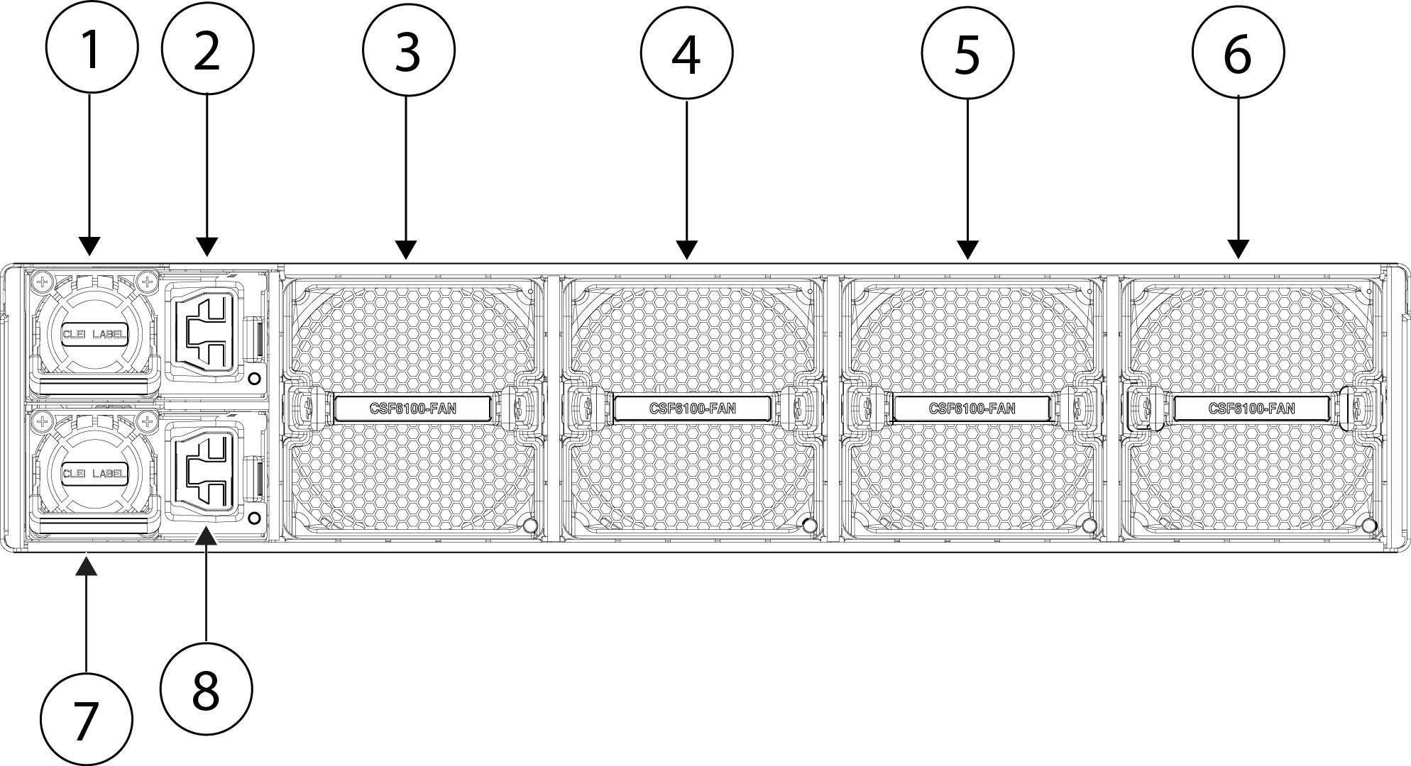
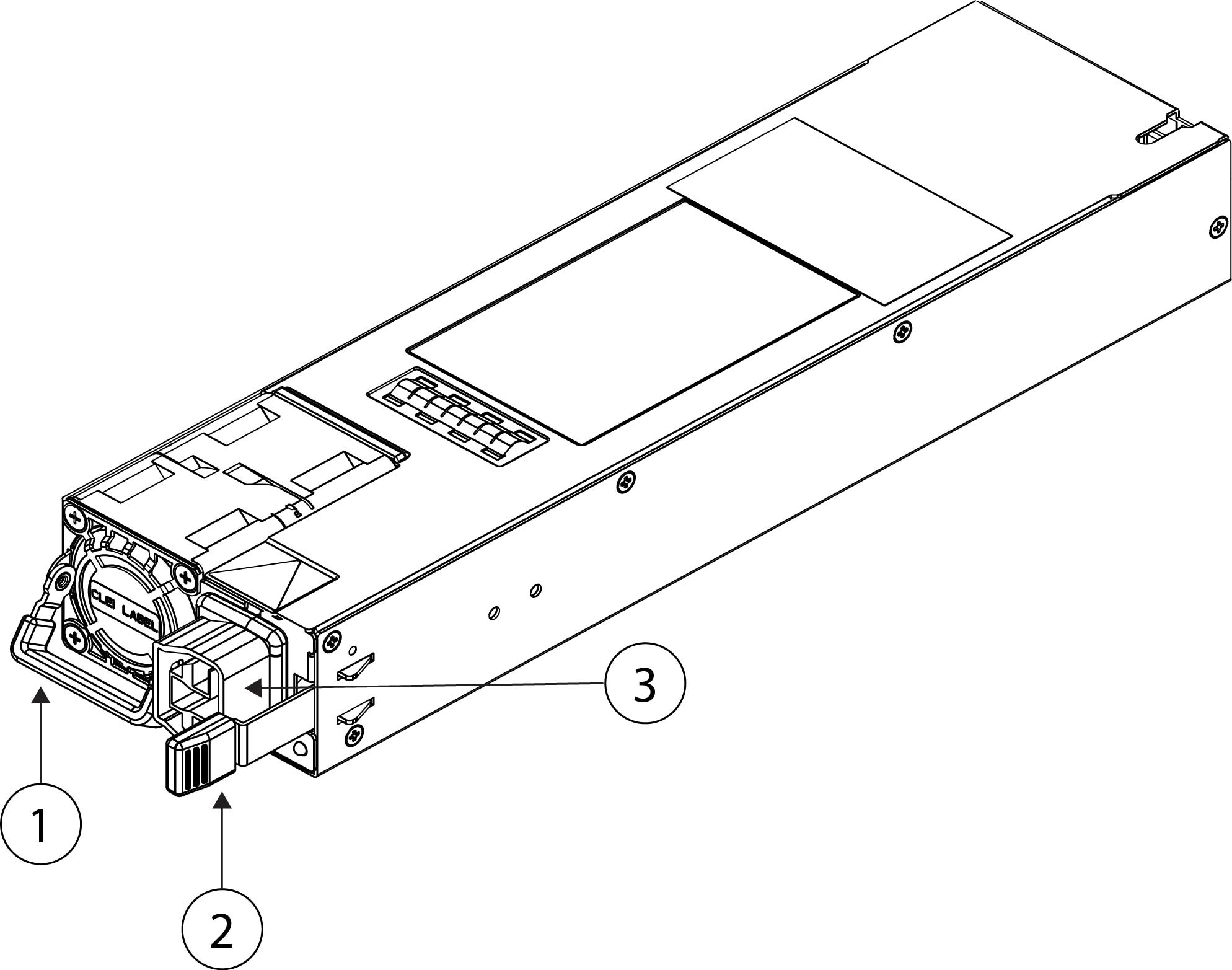
Power supply |
Dual high-voltage AC/DC power supplies Supports HVAC and HVDC
|
|||
|
Redundant power |
Yes 1 + 1 redundancy with dual HVAC/HVDC
|
|||
|
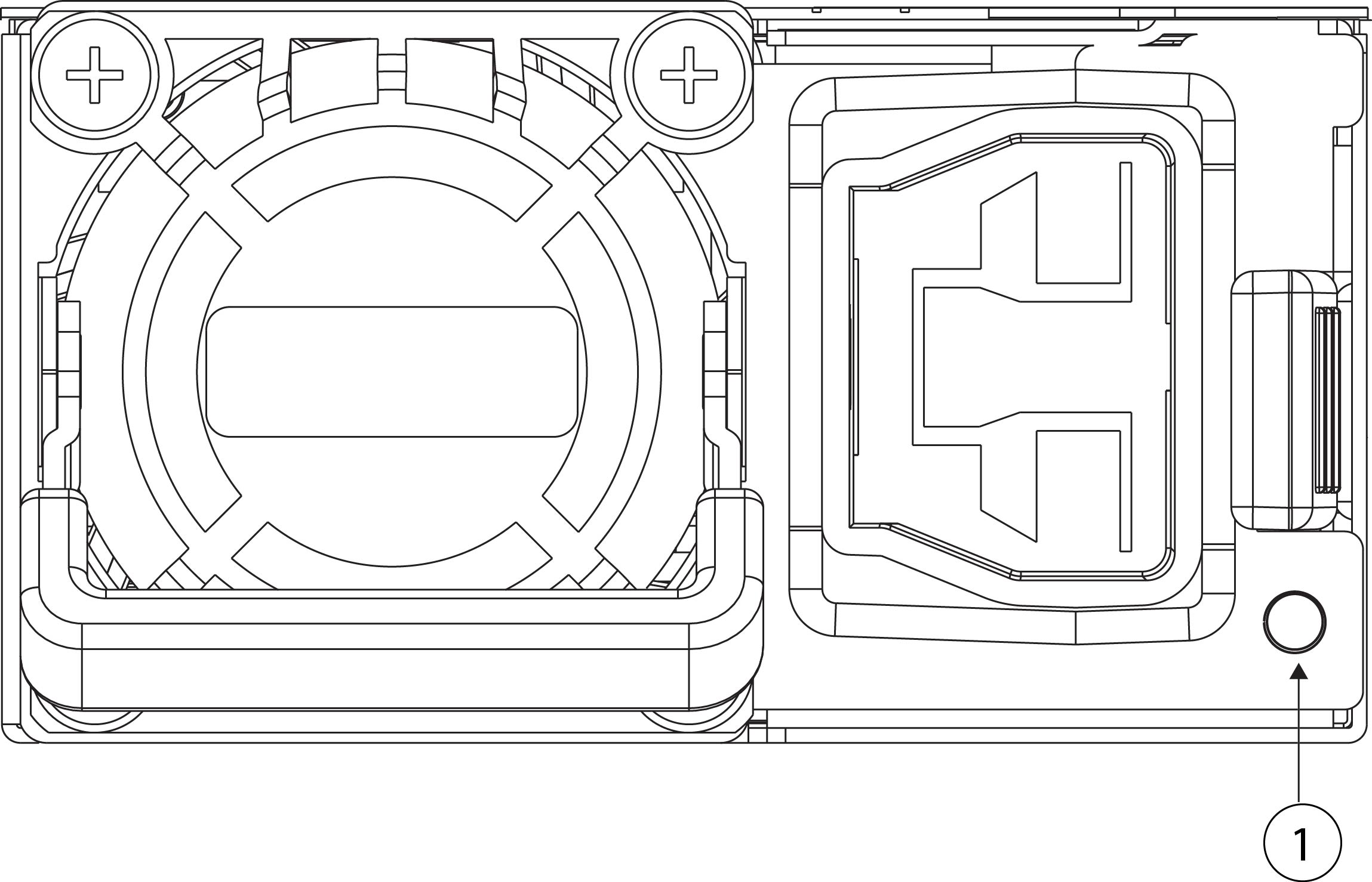
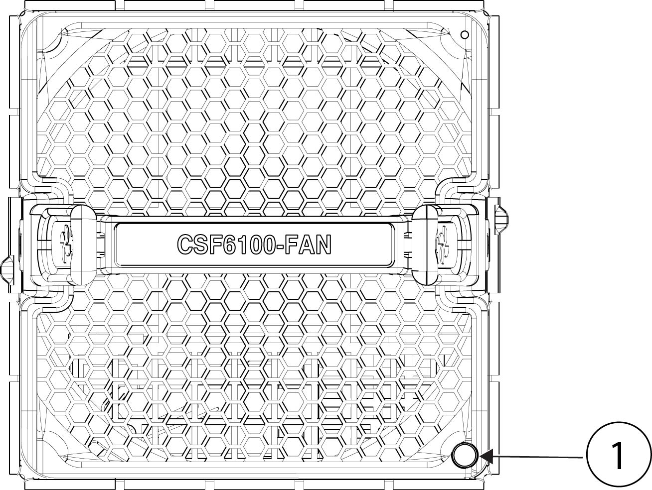
Fans |
Four redundant dual-rotor fan modules; every module has 2 fans (hot-swappable) |
|||
|
Storage |
Two SSD drives Ships with two 3.6-TB SSDs; factory-configured for RAID1. |
Two SSD drives Ships with two 7.2-TB SSDs; factory-configured for RAID1. |
||
|
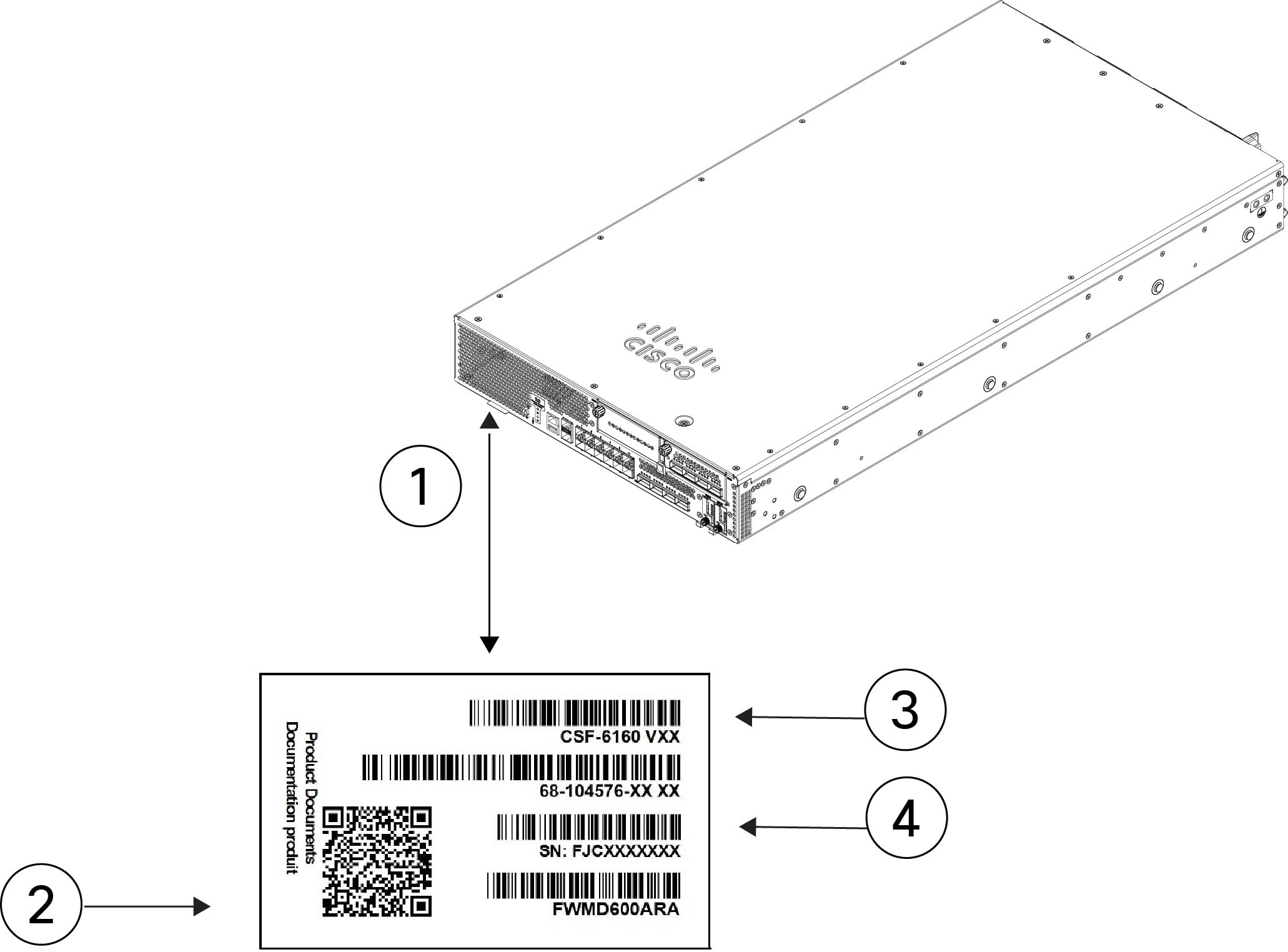
Pullout asset card |
Displays the serial number and a QR code that points to the Documentation Portal |
|||
|
Grounding |
Grounding pad on the left side of chassis facing the rear panel |
|||
|
Power button |
Controls the system's power; on front left panel |
|||
|
Reset button |
Resets the system to factory default without requiring serial console access; on front left panel. |
|||


 Feedback