Installation, Maintenance, and Upgrade

Install, remove, and replace the network module

You can remove and replace the network modules (NM-2 and NM-3) in the Secure Firewall 6100 series. Although the hardware supports removing and replacing the network module while the system is running, the software does not currently support hot swapping. You must power down the chassis or disable the network slot to remove and replace network modules.

See the configuration guide for your operating system for the procedure for managing network modules.

This procedure describes how to install a network module into an empty slot that has never contained a network module, and how to remove an installed network module and replace it with another network module.

Procedure


Step 1

To install a network module for the first time into an empty slot, do the following:

  1. Power down the chassis by pushing the power button.

    See Front panel for more information about the push power button. See the configuration guide for your operating system for the procedure for installing a network module for the first time into an empty slot.
  2. Follow Steps 4 through 7 to install the new network module.

  3. Power on the chassis by pushing the power button.

Step 2

To remove and replace an existing network module, do the following:

  1. Save your configuration.

  2. To replace an existing network module with the same model network module, disable the network slot. See the configuration guide for your operating system for the procedure to replace an existing network module with the same model.

  3. To replace an existing network module with a different model network module, power down the chassis by pushing the power button to the OFF position. See the configuration guide for your operating system for the procedure to replace an existing network module with a new model.

    See Front panel for more information about the push power button.
  4. Continue with Step 3.

Step 3

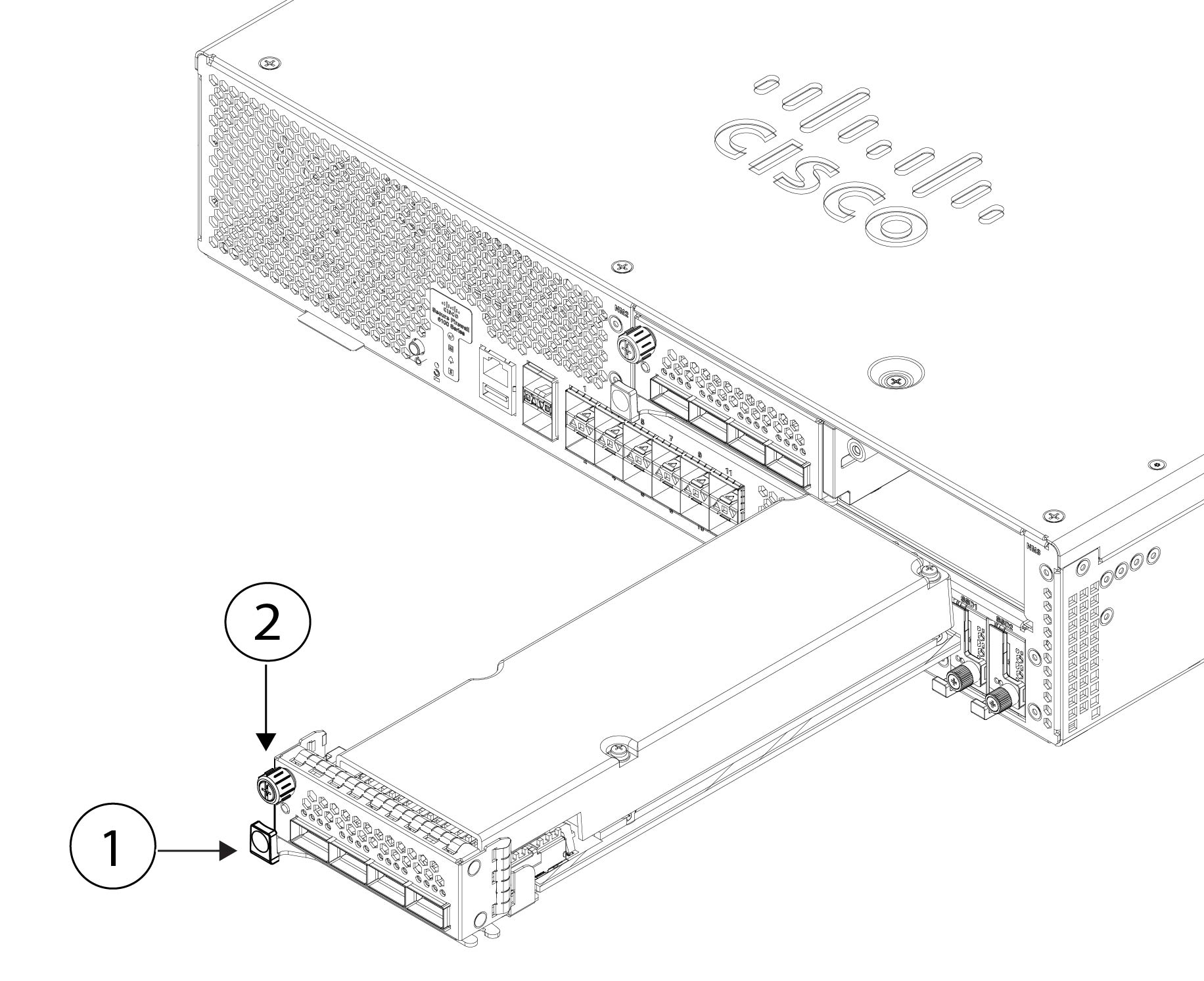
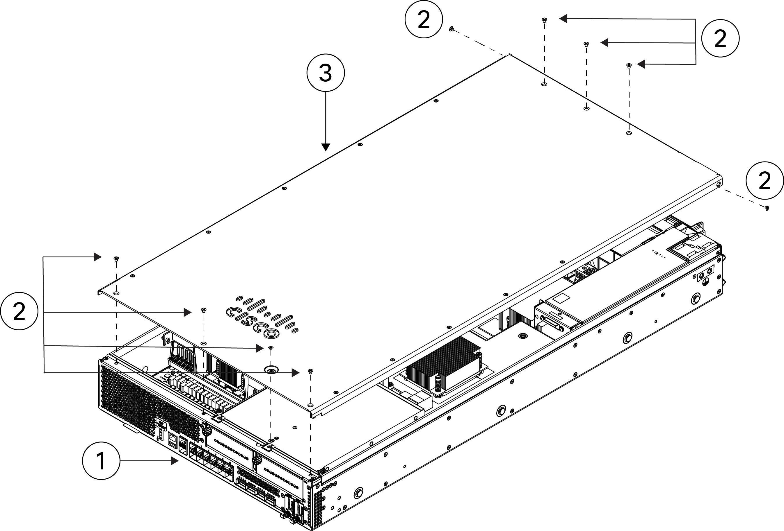
To remove a network module, loosen the captive screw on the upper left side of the network module, press the handle ejector, and pull out the handle. This mechanically ejects the network module from the slot.

Caution


The captive screw is not attached to the handle. Be sure the captive screw is completely loosened before pulling the ejector handle out. Otherwise you could damage the ejector handle as the captive screw and handle fight each other.

Figure 1. Remove the network module

1

Ejector handle

2

Captive screw

If the slot is to remain empty, install a blank faceplate to ensure proper airflow and to keep dust out of the chassis; otherwise, install another network module.

Step 4

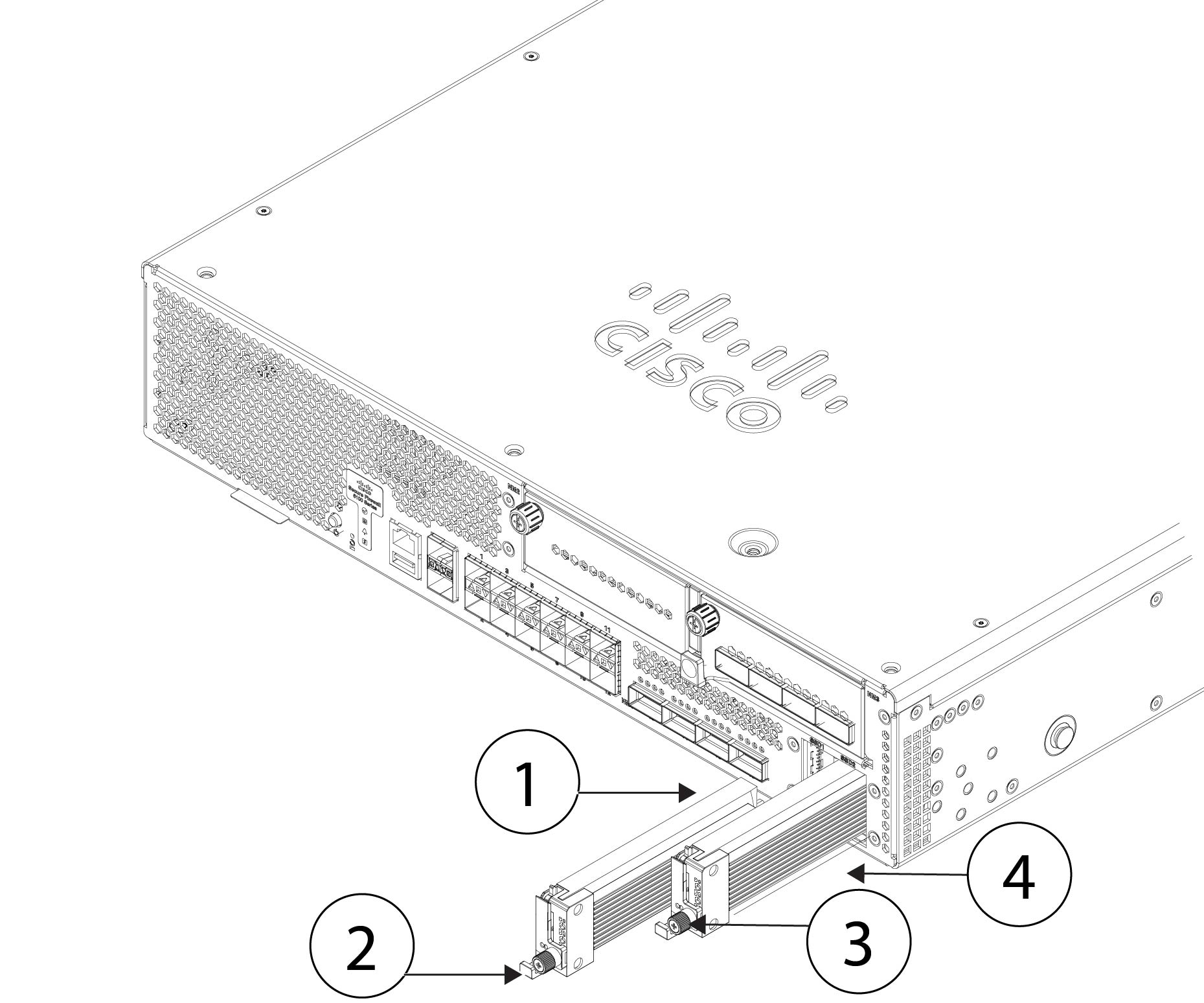
To replace a network module, hold the network module in front of the network module slot on the right of the chassis, press the ejector handle, and pull out the handle.

Step 5

Slide the network module into the slot, push it firmly into place, and close the handle on the front of the network module.

Step 6

Tighten the captive screw on the upper left side of the network module.

Step 7

Power on the chassis so that the new network module is recognized.


Remove and replace the SSD

The chassis supports two NVMe SSDs. The SSDs are configured for SW RAID1 support. See SSDs for more information.


Caution


Hot swapping for the RAID configuration is not supported. To remove an SSD, you must remove it from the RAID configuration using the raid remove-secure local-disk 1|2 command. See Hot Swap an SSD on the Secure Firewall 3100/4200 for the procedures for safely removing an SSD.


Procedure


Step 1

Save your configuration.

Step 2

Remove SSD-1 or SSD-2 from the RAID1 configuration by using the raid remove-secure local-disk 1|2 command.

Step 3

To remove the SSD from the slot, face the front of the chassis, and pinch the release tab on the front of the SSD. This causes the ejector handle to spring open.

Step 4

Grasp the ejector handle to gently pull the SSD out of the chassis.

Figure 2. Remove the SSD

1

SSD-1 slot

2

Handle

3

Captive screw

4

SSD-2 slot

Step 5

To replace SSD-1 or SSD-2, hold the SSD with the ejector handle extended in front of the slot, push it in gently until it is seated, and then close the ejector handle.

Step 6

Check the SSD LED to make sure the SSD is operative. See Front panel LEDs for a description of the SSD LEDs.

Step 7

Add the new SSD to the RAID configuration using the raid add local-disk 1|2 command.


Remove and replace the fan module

You can remove and replace the dual-rotor fan modules while the chassis is running. There are four fan modules in the rear of the chassis. The air flow moves from front to back (I/O side to non-I/0 side). They are labeled FAN-1 though FAN-4 from left to right on the rear of the chassis.


Caution


Removing all of the fan modules exposes the chassis to no airflow. The chassis does not power up and boot properly if the fan modules are missing.


Caution


If a fan module fails, remove it from the chassis and replace it within 30 seconds. After 30 seconds the CPU temperature can exceed the operating temperature, which can reduce performance.


Safety warnings

Take note of the following warnings:


Warning


Statement 1093—Avoid Sharp Edges

Risk of personal injury. Avoid sharp edges when installing or removing replaceable units.


Procedure


Step 1

Have the fan module ready for immediate insertion and near the chassis so that you can reinstall it within 30 seconds.

Step 2

To remove a fan module, face the rear of the chassis, and press the squeeze tabs on the sides of the fan module to loosen it from the chassis.

Step 3

Grasp the handle and pull the fan module out of the chassis.

Figure 3. Remove the fan module

1

Squeeze tab

2

Handle

3

Squeeze tab

Step 4

To replace a fan module, hold the fan module in front of the fan slot.

Step 5

Press the squeeze tabs on the sides of the fan module and push it into the chassis.

Step 6

Grasp the handle and push until the fan module is properly seated.

If the system is powered on, listen for the fans. You should immediately hear the fans operating. If you do not hear the fans, make sure the fan module is inserted completely into the chassis and the faceplate is flush with the outside surface of the chassis.

Step 7

Verify that the fan is operational by checking the fan module LED. See Fan modules for a description of the fan LED.


Remove and replace the power supply module

Power supply modules are hot-swappable. You can remove and replace power supply modules while the system is running. The SAF-D-GRID connector acts as a disconnect for AC/HVAC/HVDC power supply.

Safety Warnings

Take note of the following warnings:


Warning


Statement 1046—Installing or Replacing the Unit

To reduce risk of electric shock, when installing or replacing the unit, the ground connection must always be made first and disconnected last.

If your unit has modules, secure them with the provided screws.


Procedure


Step 1

Unplug the power supply cable before removing the power supply module. You cannot disengage the power supply module release tab without first removing the cable.

Step 2

To remove a power supply module, face the back of the chassis and grasp the handle.

Step 3

Press the release tab toward the left to disengage the power supply. The release tab is found on the right side of the power supply.

Step 4

Place your other hand under the power supply module to support it while you slide it out of the chassis.

Figure 4. Remove the power supply module

1

Handle

2

Power connector

3

Release tab

If the slot is to remain empty, install a blank faceplate to ensure proper airflow; otherwise, install another power supply module.

Step 5

To replace a power supply module, hold the power supply module with both hands and slide it into the power supply module bay.

Step 6

Push in the power supply module gently until you hear the release tab engage and the power supply is seated.

Step 7

Plug in the power supply cable.

Step 8

Check the LED on the power supply module to make sure the power supply is operative. See Power supply modules for a description of the power supply module LED.


Remove and replace DIMMs

This procedure describes how to remove and replace faulty DIMMs in the Secure Firewall 6100. DIMM-related failures are identified at bootup at which point the system is placed into fail-safe mode and you can use the CLI to identify fault DIMMs as seen below.


Note


You cannot directly order the DIMM replacements. You must work with TAC to get the new DIMMs so that you do not void your warranty.


Caution


To prevent ESD damage, wear grounding wrist straps during this procedure and handle the DIMMs by the carrier edges only.


Identify faulty DIMMs
Use the show dimm detail CLI command to determine which DIMMs are faulty. Also, at bootup, if a DIMM failure is detected, you will see that it is missing from the DIMM list. The following example shows that no DIMMs have failed. All 24 DIMMs are listed in both CPUs.

This example output is only seen on the serial console when ROMMON is booting.

firepower-6160# scope server 
firepower-6160 /chassis/server # scope memory-array 1
firepower-6160 /chassis/server/memory-array # show dimm detail
DIMMs installed: 
CPU1 CHANNEL A CPU1 CHANNEL B CPU1 CHANNEL C CPU1 CHANNEL D CPU1 CHANNEL E CPU1 CHANNEL F
CPU1 CHANNEL G CPU1 CHANNEL H CPU1 CHANNEL I CPU1 CHANNEL J CPU1 CHANNEL K CPU1 CHANNEL L
CPU2 CHANNEL A CPU2 CHANNEL B CPU2 CHANNEL C CPU2 CHANNEL D CPU2 CHANNEL E CPU2 CHANNEL F
CPU2 CHANNEL G CPU2 CHANNEL H CPU2 CHANNEL I CPU2 CHANNEL J CPU2 CHANNEL K CPU2 CHANNEL L

The following example shows that there is a DIMM failure. CPU1 CHANNEL L is missing.

DIMMs installed: 
CPU1 CHANNEL A CPU1 CHANNEL B CPU1 CHANNEL C CPU1 CHANNEL D CPU1 CHANNEL E CPU1 CHANNEL F
CPU1 CHANNEL G CPU1 CHANNEL H CPU1 CHANNEL I CPU1 CHANNEL J CPU1 CHANNEL K 
CPU2 CHANNEL A CPU2 CHANNEL B CPU2 CHANNEL C CPU2 CHANNEL D CPU2 CHANNEL E CPU2 CHANNEL F 
CPU2 CHANNEL G CPU2 CHANNEL H CPU2 CHANNEL I CPU2 CHANNEL J CPU2 CHANNEL K CPU2 CHANNEL L
WARNING: This system needs more memory device(s). Expected 24, installed 23
%WARNING% - Please correct the memory issue to assure best performance.
Safety Warnings

Take note of the following warnings:


Warning


Statement 1093—Avoid Sharp Edges

Risk of personal injury. Avoid sharp edges when installing or removing replaceable units.


Follow these steps to remove and replace a faulty DIMM in the Secure Firewall 6100 chassis:


Caution


DIMMs and their sockets are fragile and must be handled with care to avoid damage during installation.


Caution


Cisco does not support third-party DIMMs. Using non-Cisco DIMMs can result in system problems or damage to the internal board.


Before you begin

  • Contact TAC to verify DIMM failure and to obtain replacement DIMM(s).

  • Schedule a maintenance window for the affected Secure Firewall 6100 after receiving the replacement DIMM(s).

  • Have an ESD strap and mat ready to use during the procedure.

  • Remove all sources of power from the chassis.


    Note


    See Power button and reset button for the procedure to power off the chassis.


  • Remove the chassis from the rack.

Procedure


Step 1

Record the CPU and Channel designation for the faulty DIMM(s).

Step 2

Remove all sources of power from the chassis.

For AC systems, disconnect the AC inlet from the power supply module.

For DC systems, turn off the disconnect switch or circuit breaker and remove the power supply module from the chassis.

Step 3

Remove the chassis from the rack.

See Rack-mount the chassis using slide rails for the procedure to remove the chassis from the rack.

Step 4

Place the chassis on an antistatic mat.

Step 5

Remove the seven screws from the top of the chassis cover and the two screws on the sides. Pull the cover up and off the chassis.

Figure 5. Remove the chassis cover

1

Front panel (I/O side)

2

Chassis cover screws (9)

3

Chassis cover

Step 6

Remove the screw on the air baffle and then lift it up and out.

The air baffle covers the top DIMM banks and the two CPUs.

Figure 6. Remove the air baffle from the internal board

1

Air baffle

2

Air baffle screw

3

DIMM bank

4

CPU 1

Step 7

Locate the DIMM you are removing on the internal board.

There are four DIMM banks with six DIMM slots per bank.

Figure 7. DIMM banks on the internal board

1

DIMM bank with channels L, K, J, I, H, G

2

DIMM bank with channels F, E, D, C, B, A

3

DIMM bank with channels A, B, C, D, E, F

4

DIMM bank with channels G, H, I, J, K, L

Step 8

Open the DIMM slot latches by pressing down on the ejectors at both ends of the slot; pull the DIMM up and out.

Figure 8. Open DIMM connector latches

1

DIMM

2

DIMM notch

3

DIMM slot notch

4

Open DIMM connector latches

Step 9

Align the new DIMM with the empty slot on the internal board of the chassis. Use the alignment feature in the DIMM slot to correctly orient the DIMM.

Note


Make sure the notch in the DIMM lines up with the slot. If the slot is misaligned, you can damage the DIMM or slot.

Step 10

Push down evenly on the top two corners of the DIMM until it is fully seated and the ejector levers on both ends of the DIMM lock into place.

Step 11

Lower the air baffle back in place and tighten the screw (see the Remove the air baffle from the internal board figure above).

Step 12

Replace the chassis cover and tighten the nine screws (see the Remove the chassis cover Figure above).

Step 13

Install the chassis in the rack.

See Rack-mount the chassis using slide rails for the procedure to remove the chassis from the rack.

Step 14

Connect the power supply modules.

Step 15

Bring the Secure Firewall 6100 back online.

See the FXOS Configuration Guide for your software version for the instructions to bring the chassis back online.