Overview

Features

The Cisco Secure Firewall 4200 is a standalone modular security services platform that includes the Secure Firewall 4215, 4225, and 4245. It supports Cisco Secure Firewall Threat Defense and Cisco Secure ASA software.

The following figure shows the Secure Firewall 4200.
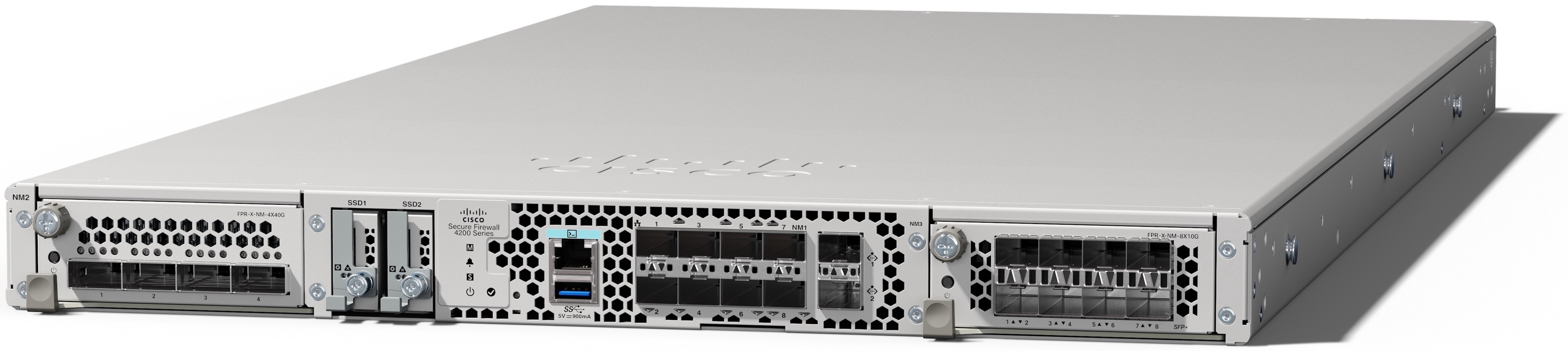
Figure 1. Secure Firewall 4200
Secure Firewall 4200

The following table lists the features for the Secure Firewall 4200.

Table 1. Secure Firewall 4200 features

Feature

4215

4225

4245

Form factor

1 RU

Fits a standard 19-inch (48.3-cm) square-hole rack

Rack mount

Two slide-rail mounting brackets and two slide rails

4-post Electronic Industries Association (EIA)-310-D rack

Airflow

Front to rear (I/O side to non-I/O side)

Cold aisle to hot aisle

System memory

256 GB

512 GB

1 TB

Management ports

Two 1/10/25-Gbps SFP28 ports

Console port

One RJ-45 serial port

USB port

One USB 3.0 with 5 W Type A port

Network ports

Eight fixed 1/10/25-Gbps SFP28 fiber ports

Named Ethernet 1/1 through 1/8

Network module slots

Two (hot-swappable)

Note


Hot-swapping of identical modules is supported, but if you replace a network module with another type, you must reboot the system so that the new network module is recognized.

Network modules

See Management, console, USB, and network ports for a list of supported network modules.

SFPs

See Supported transceivers for a list of supported SFPs.

AC power supply module

Ships with one 1900 W AC power supply module (second power supply module is optional)

Hot-swappable

Ships with two 1900 W AC power supply modules

Hot-swappable

DC power supply module

Yes (optional) 1500 W DC power supply module

Hot-swappable

Redundant power

Yes

Note


You must order a second power supply.

Yes

Note


Ships with two power supplies.

Fans

Three dual fan modules (hot-swappable)

Storage

Two Nonvolatile Memory Express (NVMe) SSD slots for EDSFF (Enterprise & Datacenter SSD Form Factor) SSD drives

Ships with two 1.8-TB SSDs; factory-configured for RAID1.

Pullout asset card

Displays the serial number and a QR code that points to the Documentation Portal

Grounding

Grounding pad on the left side of chassis near the rear power switch; use the grounding lug kit that ships with the chassis.

Power switch

On rear panel

Reset button

Resets the system to factory default without requiring serial console access

Note


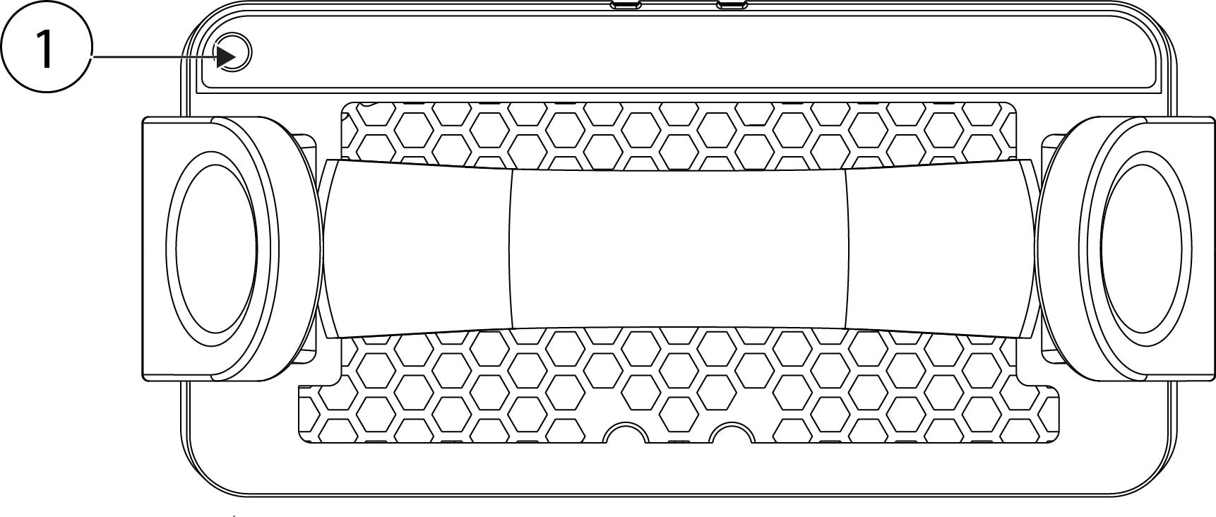
The reset button is recessed. Press with a pin and hold longer than 5 seconds to set the system back to the factory default.

Package contents

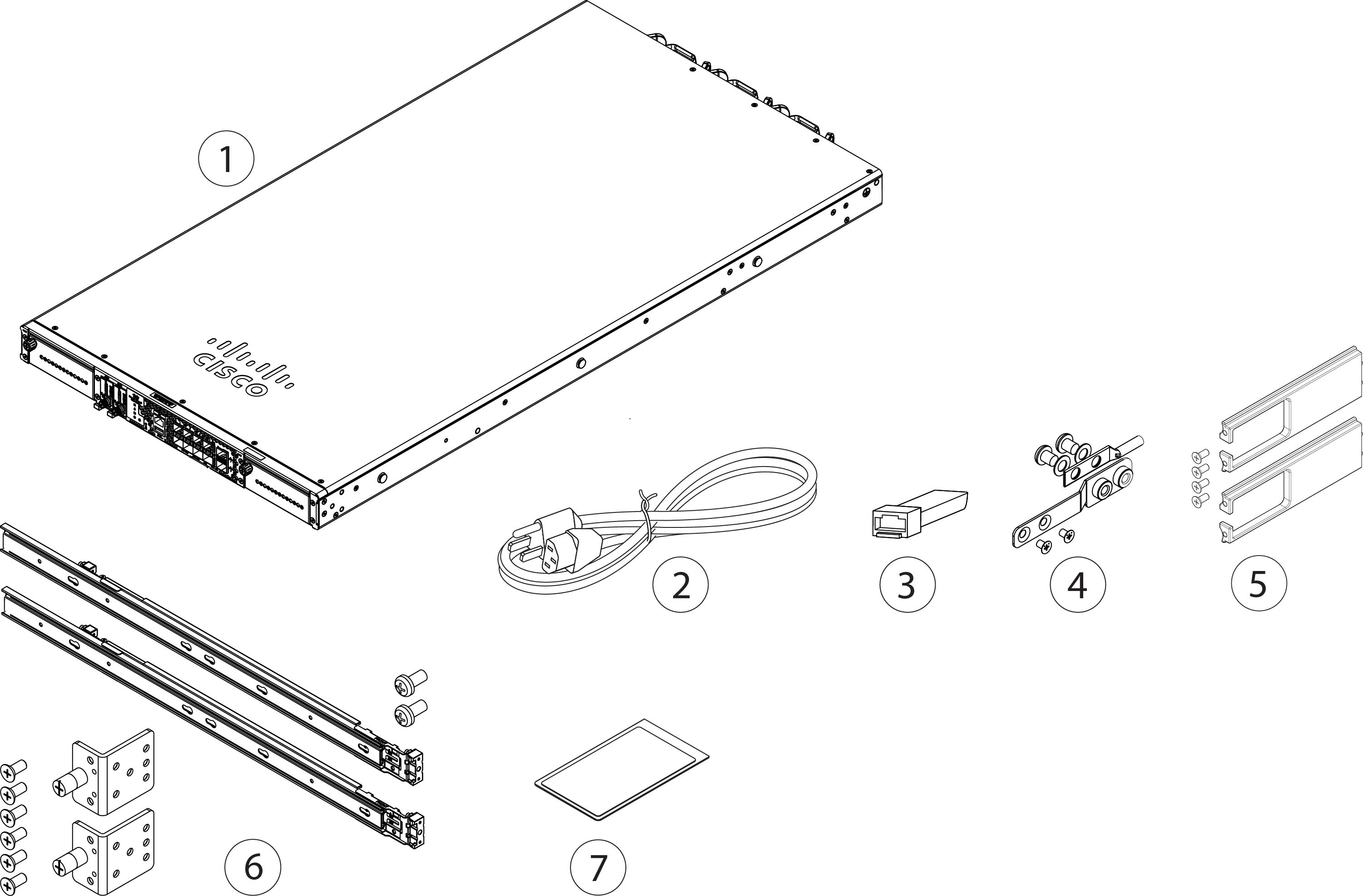
The following figure shows the package contents for the Secure Firewall 4200. The contents are subject to change and your exact contents contain additional or fewer items depending on whether you order the optional parts.

Figure 2. Secure Firewall 4200 package contents
Secure Firewall 4200 package contents

1

Secure Firewall 4200 chassis

2

One or two power cords (country-specific)

3

SFP transceiver

(Optional; in package if ordered)

4

Ground lug, screws, and washers

  • One ground lug

  • One ground lug bracket

  • Two M4.0 x 0.6 mm flat head Phillips screws

  • Two ¼-20 x 0.297-inch screws

  • Two 0.469-inch OD, 0.261-inch ID, 0.025-inch T washers

5

Cable management bracket kit

  • Two cable management brackets

  • Four 8-32 x 0.375-inch Phillips screws

(Optional; in package if ordered)

6

Two slide rails

Slide rail accessories kit:

  • Two slide rail mounting brackets

  • Six 8-32 x 0.302-inch slide rail mounting bracket Phillips screws for securing the brackets to the chassis

  • Two M3 x 0.5 x 6-mm Phillips screws for securing the chassis to your rack

7

Cisco Secure Firewall 4200

This document has links to the hardware installation guide, regulatory and safety information guide, and warranty and licensing information. It also contains a QR code and URL that point to the Digital Documentation Portal. The portal contains links to the product information page, the hardware installation guide, the regulatory and safety information guide, and the getting started guide.

—

Serial number and documentation portal QR code

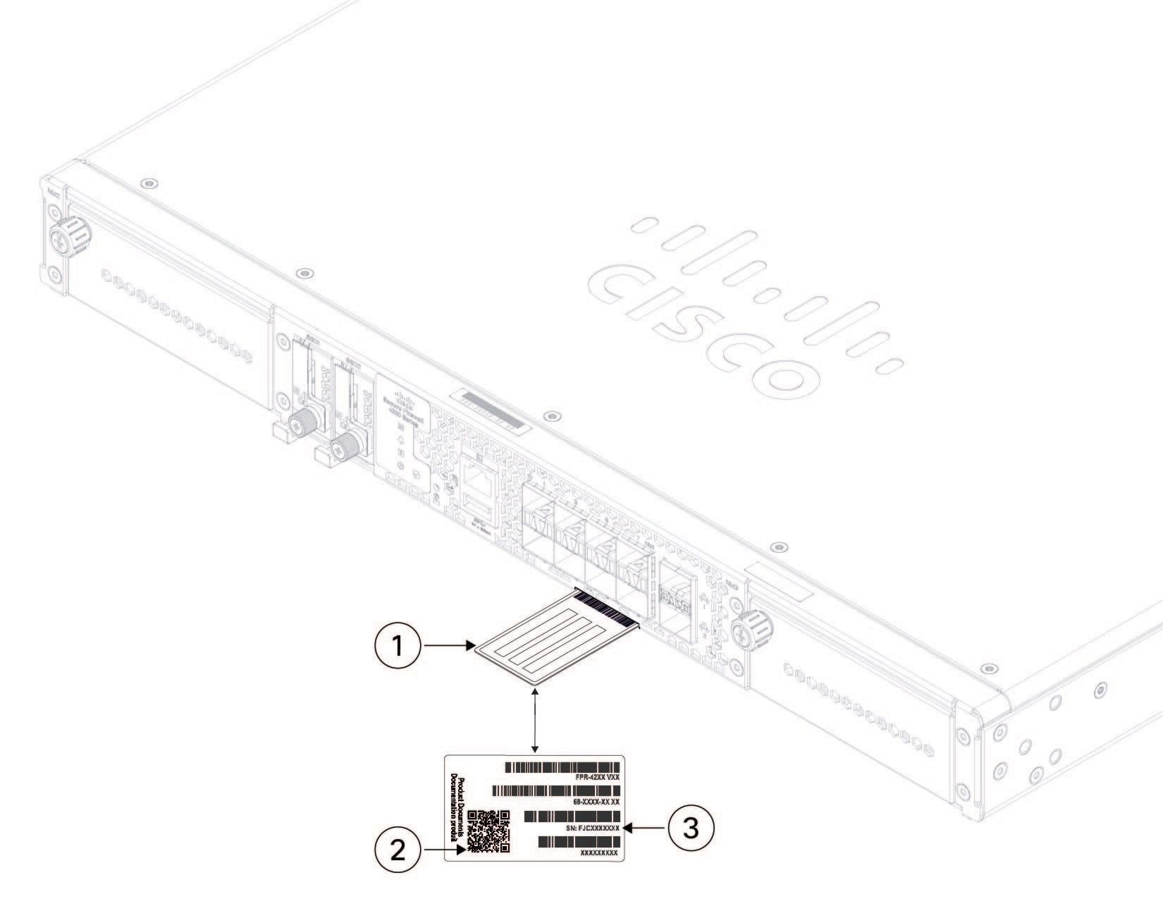
The pullout asset card on the front panel of the Secure Firewall 4200 chassis contains the chassis serial number and the Documentation Portal QR code, which points to product information, the getting started guide, the regulatory and compliance guide, and the hardware installation guide.

Figure 3. Pullout asset card
Pullout asset card

1

Pullout asset tag

2

Documentation Portal QR code

3

Chassis serial number

—

The compliance label on the bottom of the chassis contains the chassis serial number, regulatory compliance marks, and also the Documentation Portal QR code that points to the guides listed above. The following figure shows an example compliance label found on the bottom of the chassis.

Figure 4. Example compliance label
Example compliance label

1

Chassis model number

2

Documentation Portal QR code

3

Serial number

—

Front panel

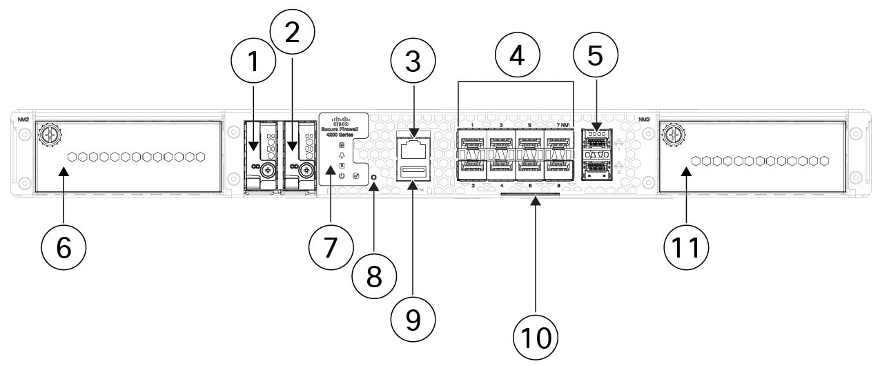
The following figure shows the front panel of the Secure Firewall 4200.

Figure 5. Secure Firewall 4200 front panel
Secure Firewall 4200 front panel

1

SSD slot (SSD-1)

2

SSD slot (SSD-2)

3

RJ-45 console port

4

Eight 1/10/25-Gbps SFP28 fixed fiber ports (NM-1)

Fiber ports named 1/1 through 1/8 left to right

5

Dual stacked management ports (supports 1/10/25-Gbps Gigabit Ethernet)

Top port:

  • Secure Firewall Threat Defense—Management 0 (also referred to as Management 1/1)

  • ASA—Management 1/1

Bottom port:

  • Secure Firewall Threat Defense—Management 1 (also referred to as Management 1/2)

  • ASA—Management 1/2

6

Network module slot (NM-2)

7

System LEDs

8

Recessed factory reset button

9

Type A USB 3.0 port

10

Pullout asset card with chassis serial number and QR code to the Digital Documentation Portal that has links to the getting started guide, hardware guide, and regulatory and compliance guide.

11

Network module slot (NM-3)

—

Front panel LEDs

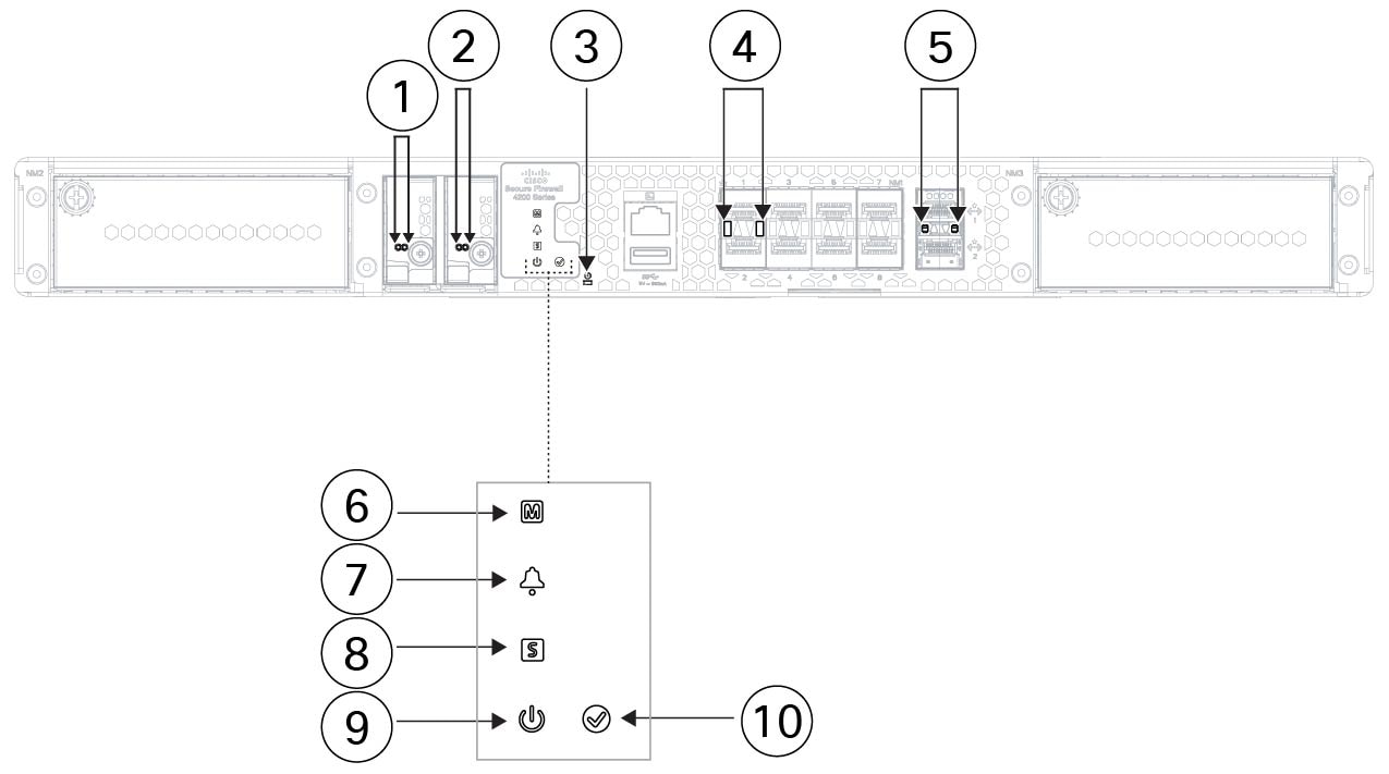
The following figure shows the Secure Firewall 4200 front panel LEDs.

Figure 6. Secure Firewall 4200 front panel LEDs
Secure Firewall 4200 front panel LEDs

1

SSD-1 status

Note


The left LED is active. The right LED is always off.

  • Off—The SSD is not present.

  • Green—The SSD is present; no activity.

  • Green, flashing—The SSD is active.

  • Amber—The SSD has a problem or failure.

2

SSD-2 status

Note


The left LED is active. The right LED is always off.

  • Off—The SSD is not present.

  • Green—The SSD is present; no activity.

  • Green, flashing—The SSD is active.

  • Amber—The SSD has a problem or failure.

3

Factory reset button status
  • Green, flashing—Flashes 5 seconds after you depress the button.

  • Off—Reset is complete.

Note


The factory reset button begins flashing after it has been depressed for at least 5 seconds, and persists until the software has completely applied all factory default settings or it is interrupted by a power cycle.

4

Fiber port link/activity status

Each fiber port has one dual color LED under the SFP cage.

  • Off—No SFP.

  • Green—Link up.

  • Green, flashing—Network activity at >1G is detected.

  • Amber—No link or network failure.

5

Management port status

The 1/10/25-Gbps fiber management port has a bicolor LED under the SFP cage that indicates link/activity/fault:

  • Off—No SFP.

  • Green—Link up.

  • Green, flashing—Network activity.

  • Amber—SFP present, but no link.

6

Managed status

Reserved for future use.

7

Alarm status

  • Off—No alarms.

  • Amber—Environmental error.

  • Green—Status is ok.

8

System status

  • Off—System has not booted up yet.

  • Green, flashing quickly—System is booting up.

  • Green—Normal system function.

  • Amber—System boot up has failed.

  • Amber, flashing—Alarm condition, system needs service or attention and may not boot properly.

9

Power status

  • Off—System is powered off. If the AC power cord is plugged in, and the LED on the power supply is blinking green, standby power is still on.

    Note


    If the LED is off, then the power switch is set to OFF or there is no input power.

  • Green, flashing—The system has detected a power switch toggle event, and initiated the shutdown sequence. If the power switch is in the OFF position, the system powers off after shutdown is completed. Do not remove the AC or DC power source while this LED is blinking so that the system has time to perform a graceful shutdown.

  • Amber—The system is powering up (before the BIOS boots). This takes one to five seconds at most.

  • Green—The system is fully powered up.

10

Activity status (Role of a high-availability pair)

  • Off—The unit is not configured or enabled in a high-availability pair.

  • Green—The unit is in active mode.

  • Amber—The unit is in standby mode.

Management, console, USB, and network ports

Management port

The Secure Firewall 4200 chassis management port is a 1/10/25-Gbps SFP port that supports fiber as well as DAC or GLC-TE.

RJ-45 console port

The Secure Firewall 4200 does not ship with an RJ-45 serial cable unless you order it with the chassis. You can obtain a cable, for example, a USB-to-RJ-45 serial cable. You can use the CLI to configure your 4200 through the RJ-45 serial console port by using a terminal server or a terminal emulation program on a computer.

The RJ-45 (8P8C) port supports RS-232 signaling to an internal UART controller. The console port does not have any hardware flow control, and does not support a remote dial-in modem. The default console port settings are displayed as follows:

  • 9,600 bits per second

  • 8 data bits

  • No parity

  • 1 stop bit

  • No flow control

Type A USB 3.0 port

You can use the external Type A USB port to attach a data-storage device. The external USB drive identifier is usb:. The Type A USB port supports the following:

  • Boot kickstart image from ROMMON for discovery recovery purposes

  • Copy files to and from workspace:/ and volatile:/ within local-mgmt. The most relevant files are:

    • Core files

    • Ethanalyzer packet captures

    • Tech-support files

    • Security module log files

  • Hot swapping

  • USB drive formatted with FAT32

  • Platform bundle image upload using download image usbA:

The Type A USB port does not support Cisco Secure Package (CSP) image upload support.

Network ports

The Secure Firewall 4200 chassis has two network module slots that support the following network modules:

  • 4-port 40-Gbps QSFP/QSFP+ (FPR4K-XNM-4X40G)

  • 4-port 40/100/200-Gbps QSFP28/QSFP (FPR4K-XNM-4X200G)

  • 2-port 100-Gbps QSFP56/QSFP28/QSFP (FPR4K-XNM-2X100G)

  • 8-port 1/10-Gbps SFP (FPR4K-XNM-8X10G)

  • 8-port 1/10/25-Gbps ZSFP (FPR4K-XNM-8X25G)

  • 6-port 1-Gbps SFP SX multimode hardware bypass (FPR4K-XNM-6X1SXF)

  • 6-port 10-Gbps SFP SR multimode hardware bypass (FPR4K-XNM-6X10SRF)

  • 6-port 10-Gbps SFP LR single mode hardware bypass (FPR4K-XNM-6X10LRF)

  • 6-port 25-Gbps SFP SR multimode hardware bypass (FPR4K-XNM-6X25SRF)

  • 6-port 25-Gbps SFP LR single mode hardware bypass (FPR4K-XNM-6X25LRF)

  • 8-port 1-Gbps 1000Base-T hardware bypass (FPR4K-XNM-8X1GF)

  • 2-port 200/400-Gbps QSFP-DD (FPR4K-XNM-2X400G)

  • 2-port 100-Gbps QSFP+ hardware bypass (CSF6K-XNM-2X100SRF)

Power and reset buttons

Power switch

The power switch is located to the left of PSU-1 on the rear of the chassis. It is a toggle switch that controls power to the system. Turning the switch to OFF starts the graceful shutdown process. During the shutdown process the power LEDs flash green indicating that the process has started.  Once the shutdown is complete, the system is powered off. Wait for the system power LEDs to turn off before unplugging the AC power cables.


Caution


Threat defense requires a graceful shutdown. If you remove the system power cords before the graceful shutdown is complete, disk corruption can occur. You can move the power switch to OFF before the shutdown. The system ignores it.


Note


After removing power from the chassis by unplugging the power cord, wait at least 10 seconds before turning power back ON. You want to keep the system power off, including the standby power, for 10 seconds.


Factory reset button

The Secure Firewall 4200 chassis has a recessed reset button that resets the system to the factory default. Pressing the button down for five seconds deletes the current configuration and current files.


Note


Use the reset button if the current credentials are lost and you want to initialize the box without having console access.


The following occurs:

  • ROMMON NVRAM is cleared and returned to default.

  • All extra images are removed; the current running image remains.

  • FXOS logs, core files, SSH keys, certificates, FXOS configuration, and Apache configuration are removed.


Note


If power is lost between when you pushed the reset button and when the reset process is complete, the process stops and you have to push the button again after the system powers back on.


Rear panel

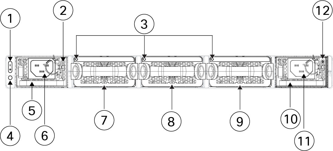
The following figure shows the rear panel of the Secure Firewall 4200.

Figure 7. Secure Firewall 4200 rear panel
Secure Firewall 4200 rear panel

1

Power on/off switch

2

Power supply LED (PSU-1)

3

Dual fan modules (FAN-1, FAN-2, FAN-3) LEDs

4

System power LED

This system power LED has the same behavior as the front panel LED.

Note


Power supply module 1 (PSU-1)

5

Power supply module 1 (PSU-1)

6

Power supply module 1 (PSU-1) connector

7

Dual fan module 1 (FAN-1)

8

Dual fan module 2 (FAN-2)

9

Dual fan module 3 (FAN-3)

10

Power supply module 2 (PSU-2)

11

Power supply module 2 (PSU-2) connector

12

Power supply LED (PSU-2)

Network modules

The Secure Firewall 4200 chassis has two network module slots named NM-2 and NM-3 (left to right on the front panel). Network modules are optional, removable I/O modules that provide either additional ports or different interface types. The network module plugs into the chassis on the front panel. See for the location of the network module slots on the chassis.

Make sure you have the correct firmware package and software version installed to support the network modules. See the configuration guide for your software for the procedures for updating the firmware package and verifying the software version.

8-Port 1/10/25-Gbps network module (FPR4K-XNM-8X10G)

FPR4K-XNM-8X10G supports 1 Gbps and 10 Gbps full-duplex Ethernet traffic per port and is supported on all Secure Firewall 4200s. FPR4K-XNM-8X25G supports 1 Gbps, 10 Gbps, or 25 Gbps full-duplex Ethernet traffic per port and is supported on all Secure Firewall 4200s.

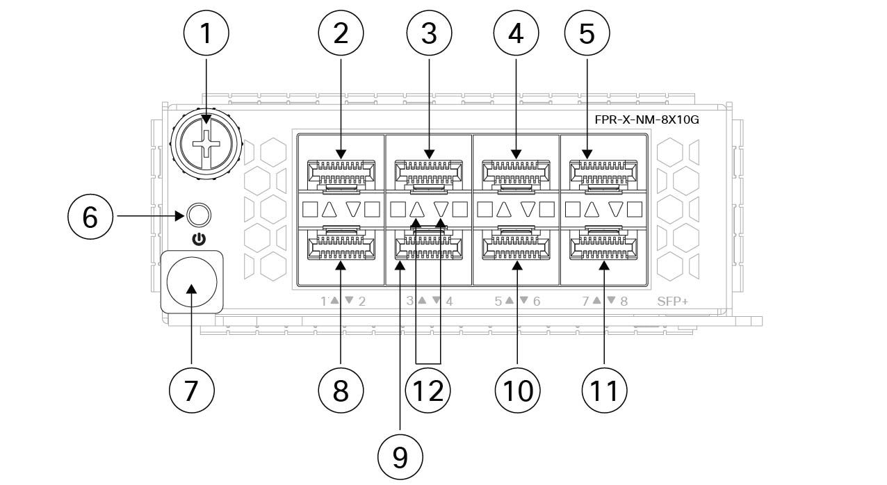
The top ports are numbered from left to right—Ethernet 2/1 or 3/1, Ethernet 2/3 or 3/3, Ethernet 2/5 or 3/5, and Ethernet 2/7 or 3/7. The bottom ports are numbered from left to right—Ethernet 2/2 or 3/2, Ethernet 2/4 or 3/4, Ethernet 2/6 or 3/6, and Ethernet 2/8 or 3/8 (see the figure below). Up arrows are the top ports and down arrows are the bottom ports (see the figure below). This network module supports SFP/SFP+/SFP28 transceivers.


Note


The hardware and the system support hot swapping if you are replacing a network module with the same type of network module. You must first disable the network port and then reenable it after replacement. If you replace the 8-port 1/10/25-Gbps network module with another supported network module, you must reboot the chassis so that the new network module is recognized. See the configuration guide for your operating system for the detailed procedures for managing network modules.


The following figure shows the front panel of the 1/10-Gbps and 1/10/25-Gbps network module.

Figure 8. FPR4K-XNM-8X10G and FPR4K-XNM-8X25G
8-Port 1/10/25-Gbps

1

Captive screw

2

Ethernet 2/1 or 3/1

3

Ethernet 2/3 or 3/3

4

Ethernet 2/5 or 3/5

5

Ethernet 2/7 or 3/7

6

Power on LED

7

Ejector handle

8

Ethernet 2/2 or 3/2

9

Ethernet 2/4 or 3/4

10

Ethernet 2/6 or 3/6

11

Ethernet 2/8 or 3/8

12

Network activity LEDs

The up arrows represent the top ports and the down arrows represent the bottom ports.

  • Off—No SFP.

  • Amber—No link or network failure.

  • Green—Link up.

  • Green, flashing—Network activity.

4-Port 40-Gbps network module (FPR4K-XNM-4X40G)

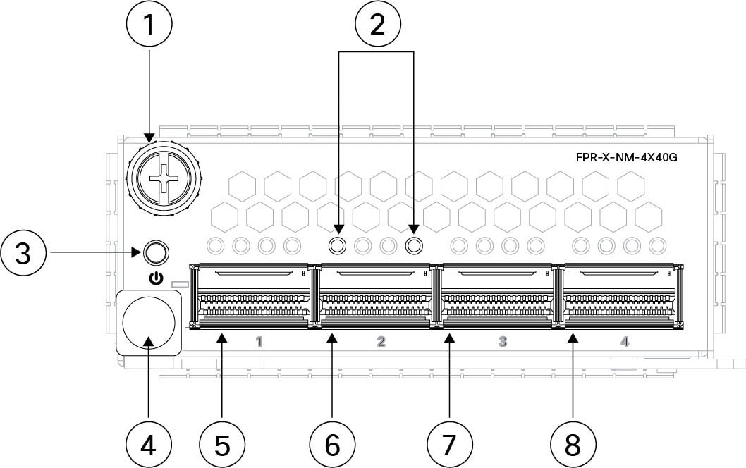
The FPR4K-XNM-4X40G supports 40-Gbps operation. This network module provides full-duplex Ethernet traffic per port. The 40-Gb network module has four QSFP+ ports. The 40-Gb ports are numbered left to right, Ethernet 2/1 or 3/1 through Ethernet 2/4 or 3/4.

You can break each of the four 40-Gbps ports into four 10-Gbps ports using the supported breakout cables. With the four-port 40-Gbps network module, you now have 16 10-Gbps interfaces. The added interfaces are Ethernet 2/1/1 or 3/1/1 through Ethernet 2/4/4 or 3/4/4.


Note


The hardware and the system support hot swapping if you are replacing a network module with the same type of network module. If you replace the 4-port 40-Gbps network module with another supported network module, you must reboot the chassis so that the new network module is recognized. See the configuration guide for your operating system for the detailed procedures for managing network modules.


The following figure shows the front panel of the 4-port 40-Gbps network module.

Figure 9. FPR4K-XNM-4X40G
4-port 40-Gbps network module

1

Captive screw

2

Network activity LEDs

The up arrows represent the top ports and the down arrows represent the bottom ports.

  • Off—No SFP.

  • Amber—No link or a network failure.

  • Green—Link is up.

  • Green, flashing—Network activity.

3

Power on LED

4

Ejector handle

5

Ethernet 2/1 or 3/1

6

Ethernet 2/2 or 3/2

7

Ethernet 2/3 or 3/3

8

Ethernet 2/4 or 3/4

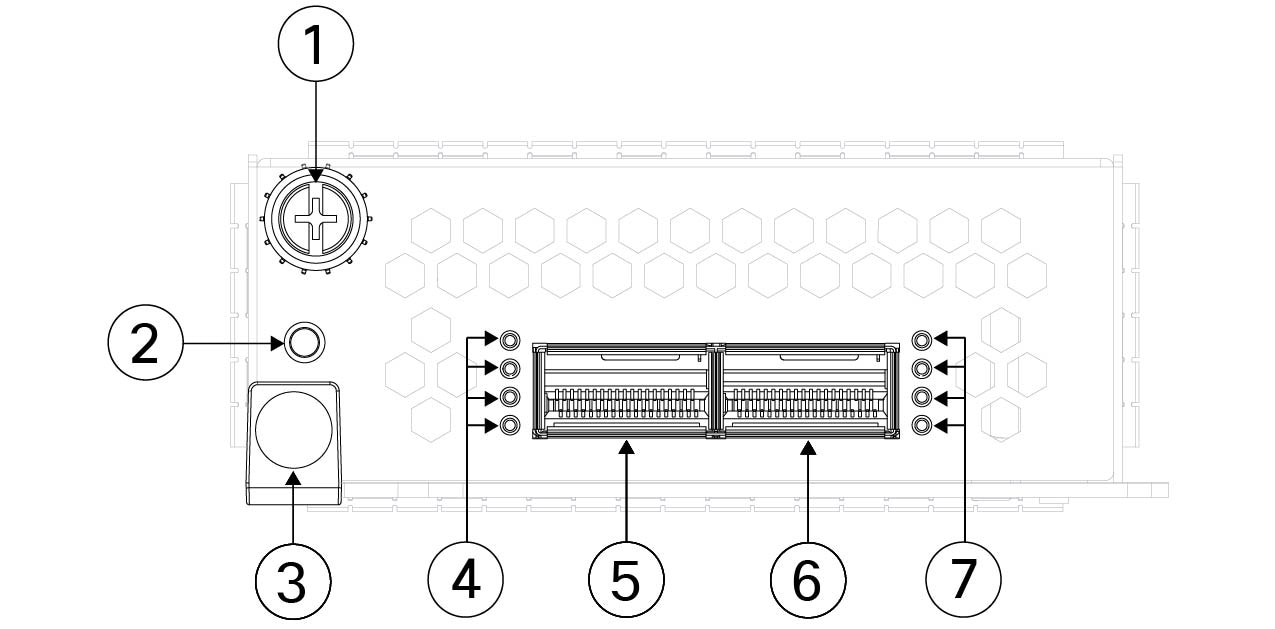
2-Port 100-Gbps network module (FPR4K-XNM-2X100G)

The FPR4K-XNM-2X100G supports 40/100-Gbps operation. This network module has two QSFP/QSFP28 ports and provides full-duplex Ethernet traffic per port. The maximum bandwidth supported is 200 Gbps full duplex, where each port operates at 100 Gbps. The 100-Gbps ports are numbered left to right, Ethernet 2/1 or 3/1 through Ethernet 2/2 or 3/2.

The network module has two 100-Gbps ports named E2/1 and E2/2. You can break each 100-Gbps port into four 10-Gbps or four 25-Gbps ports using the supported breakout cables. For E2/1 the new interfaces are named E2/1/1, E2/1/2, E2/1/3 and E2/1/4. For E2/2 the new interfaces are named E2/1/2, E2/2/2, E2/2/3, and E2/2/4.


Note


The hardware and the system support hot swapping if you are replacing a network module with the same type of network module. If you replace the 100-Gbps network module with another supported network module, you must reboot the chassis so that the new network module is recognized. See the configuration guide for your operating system for the detailed procedures for managing network modules.


The following figure shows the front panel of the 2-port 100-Gbps network module.


Note


When a port operates in a 40-Gbps mode, only the left-most LED of the port indicates the link/activity status.


Figure 10. FPR4K-XNM-2X100G
2-port 100-Gbps network module

1

Captive screw

2

Network activity LEDs

  • Off—No SFP.

  • Amber—No link or a network failure.

  • Green—Link is up.

  • Green, flashing—Network activity.

3

Network activity LEDs

  • Off—No SFP.

  • Amber—No link or a network failure.

  • Green—Link is up.

  • Green, flashing—Network activity.

4

Power on LED

5

Ejector handle

6

Ethernet 2/1 or 3/1

7

Ethernet 2/2 or 3/2

—

4-Port 200-Gbps network module (FPR4K-XNM-4X200G)

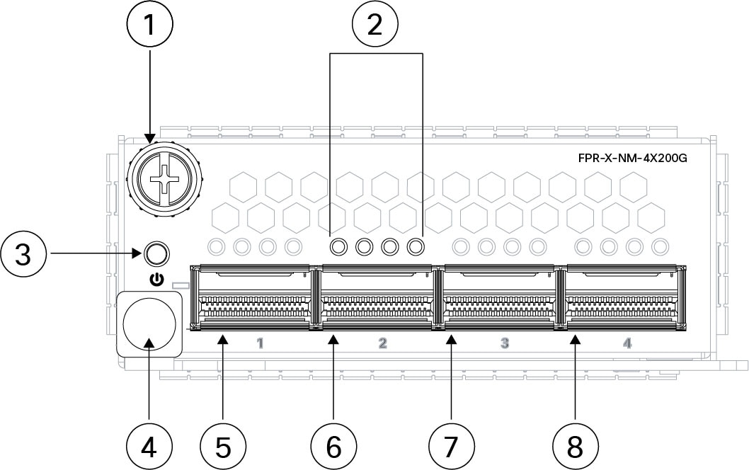
The FPR4K-XNM-4X200G supports 40/100/200-Gbps operation. This network module provides full-duplex Ethernet traffic per port. The 200-Gbps network module has four QSFP56 ports. The ports are numbered left to right, Ethernet 2/1 or 3/1 through Ethernet 2/4 or 3/4.

You can break each 100-Gbps port into four 10-Gbps or 25-Gbps ports using the supported breakout cables. With the four-port 200-Gbps network module, you now have 16 10-Gbps or 25-Gbps interfaces. The added interfaces are Ethernet 2/1/1 or 3/1/1 through Ethernet 2/4/4 or 3/4/4.


Note


The hardware and the system support hot swapping if you are replacing a network module with the same type of network module. If you replace the 4-port 200-Gbps network module with another supported network module, you must reboot the chassis so that the new network module is recognized. See the configuration guide for your operating system for the detailed procedures for managing network modules.


The following figure shows the front panel of the 4-port 200-Gbps network module.


Note


When a port operates in 40-Gvps or 100-Gbps mode, only the left-most LED of the port indicates link/activity status.


Figure 11. FPR4K-XNM-4X200G
4-port 200-Gbps network module

1

Captive screw

2

Network activity LEDs

The up arrows represent the top ports and the down arrows represent the bottom ports.

  • Off—No SFP.

  • Amber—No link or a network failure.

  • Green—Link is up.

  • Green, flashing—Network activity.

3

Power on LED

4

Ejector handle

5

Ethernet 2/1 or 3/1

6

Ethernet 2/2 or 3/2

7

Ethernet 2/3 or 3/3

8

Ethernet 2/4 or 3/4

2-Port 400-Gbps network module (FPR4K-XNM-2X400G)

The FPR4K-XNM-2X400G supports 400-Gbps operation, and is also designed to support 200-Gbps, 100-Gbps, and 40-Gbps per port. This network module provides full-duplex Ethernet traffic per port. The 400-Gbps network module supports two QSFP-DD transceivers and is designed to also support 200-Gbps QSFP56, 100-Gbps QSFP28, and 40-Gbps QSFP+ transceivers. The 400-Gbps ports are numbered left to right, Ethernet 2/1 or 3/1 through Ethernet 2/2 or 3/2.


Note


The hardware and the system support hot swapping if you are replacing a network module with the same type of network module. If you replace the 2-port 200/400-Gbps network module with another supported network module, you must reboot the chassis so that the new network module is recognized. See the configuration guide for your operating system for the detailed procedures for managing network modules.


The following figure shows the front panel of the 2-port 200/400-Gbps network module.


Note


When a port operates in 40-Gbps, 100-Gbps, or 200-Gbps mode, only the left-most LED indicates link/activity status.


Figure 12. FPR4K-XNM-2X400G
2-port 200/400-Gbps network module

1

Captive screw

2

Power on LED

3

Ejector handle

4

Network activity LEDs

  • Off—No SFP.

  • Amber—No link or a network failure.

  • Green—Link is up.

  • Green, flashing—Network activity.

5

Ethernet 2/1 or 3/1

6

Ethernet 2/2 or 3/2

7

Network activity LEDs

  • Off—No SFP.

  • Amber—No link or a network failure.

  • Green—Link is up.

  • Green, flashing—Network activity.

—

Hardware bypass network modules

Hardware bypass (also known as fail-to-wire) is a physical layer (Layer 1) bypass that allows paired interfaces to go into bypass mode so that the hardware forwards packets between these port pairs without software intervention. Hardware bypass provides network connectivity when there are software or hardware failures. Hardware bypass is useful on ports where the Firepower security appliance is only monitoring or logging traffic. The hardware bypass network modules have an optical switch that is capable of connecting the two ports when needed. The hardware bypass network modules have built-in SFPs.

Hardware bypass is supported only on a fixed set of ports. You can pair Port 1 with Port 2, Port 3 with Port 4, but you cannot pair Port 1 with Port 4 for example.

Make sure you have the correct firmware package and software version installed to support the network modules. See the configuration guide for your software for the procedures for updating the firmware package and verifying the software version.


Note


When the appliance switches from normal operation to hardware bypass or from hardware bypass back to normal operation, traffic may be interrupted for several seconds. A number of factors can affect the length of the interruption; for example, behavior of the optical link partner such as how it handles link faults and debounce timing; spanning tree protocol convergence; dynamic routing protocol convergence; and so on. During this time, you may experience dropped connections.


There are three configuration options for hardware bypass network modules:

  • Passive interfaces—Connection to a single port.

    For each network segment you want to monitor passively, connect the cables to one interface. This is how the nonhardware bypass network modules operate.

  • Inline interfaces—Connection to any two like ports (10 Gbps to 10 Gbps for example) on one network module, across network modules, or fixed ports.

    For each network segment you want to monitor inline, connect the cables to pairs of interfaces.

  • Inline with hardware bypass interfaces—Connection of a hardware bypass paired set.

    For each network segment that you want to configure inline with fail-open, connect the cables to the paired interface set.

    For the 40-Gbps network module, you connect the two ports to form a paired set. For the 1/10-Gbps network modules, you connect the top port to the bottom port to form a hardware bypass paired set. This allows traffic to flow even if the security appliance fails or loses power.


Note


If you have an inline interface set with a mix of hardware bypass and nonhardware bypass interfaces, you cannot enable hardware bypass on this inline interface set. You can only enable hardware bypass on an inline interface set if all the pairs in the inline set are valid hardware bypass pairs.


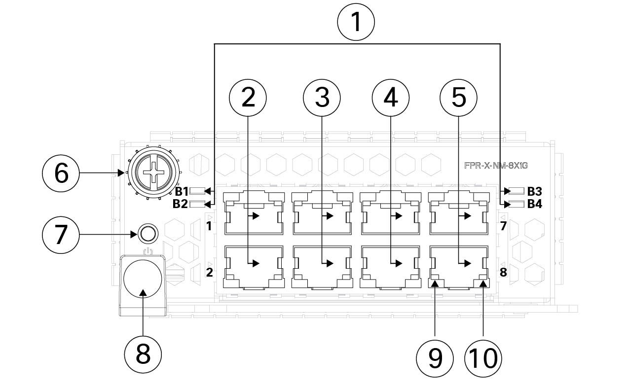
8-Port 1000Base-T network module (FPR4K-XNM-8X1GF)

FPR4K-XNM-8X1GF is an 8-port 1000Base-T hardware bypass network module. The eight ports are numbered from top to bottom, left to right. Ports 1 and 2, 3 and 4, 5 and 6, and 7 and 8 are paired for hardware bypass mode. In hardware bypass mode, data is not processed by the Secure Firewall 4200 but is routed to the paired port.

The hardware and the system support hot swapping if you are replacing a network module with the same type of network module. If you replace the 8-port 1000Base-T network module with another supported network module, you must reboot the chassis so that the new network module is recognized. See the configuration guide for your operating system for the detailed procedures for managing network modules.

The following figure shows the front panel of the 8-port 1000Base-Tnetwork module.


Note


When a port operates in 400-Gbps, 200-Gbps, 100-Gbps, or 40-Gbps mode, only the top LED of the port indicates link/activity status.


Figure 13. FPR4K-XNM-8X1GF
8-port Base-T

1

Bypass LEDs B1 through B4

  • Green—In standby mode.

  • Amber, flashing—Port is in hardware bypass mode, failure event.

2

Ethernet 2/1 and 2/2 or Ethernet 3/1 and 3/2

Ports 1 and 2 are paired together to form a hardware bypass pair. LED B1 applies to this paired port.

3

Ethernet 2/3 and Ethernet 2/4 or Ethernet 3/3 and 3/4

Ports 3 and 4 are paired together to form a hardware bypass pair. LED B2 applies to this paired port.

4

Ethernet 2/5 and 2/6 or Ethernet 3/5 and 3/6

Ports 5 and 6 are paired together to form a hardware bypass pair. LED B3 applies to this paired port.

5

Ethernet 2/7 and 2/8 or Ethernet 3/7 and 3/8

Ports 7 and 8 are paired together to form a hardware bypass pair. LED B4 applies to this paired port.

6

Captive screw

7

Power LED

8

Handle

9

Left Port LED

  • Unlit—No connection or port is not in use.

  • Green—Link up.

  • Green, flashing—Network activity.

10

Right Port LED

  • Unlit—No connection or port is not in use.

  • Green—Link up.

  • Green, flashing—Network activity.

6-Port 1-Gbps SX, 10-Gbps SR/10-Gbps LR/25-Gbps SR/25-Gbps LR network module (FPR4K-XNM-6X10SRF, FPR4K-XNM-6X10LRF, FPR4K-XNM-6X25SRF, and FPR4K-XNM-6X25LRF)

The FPR4K-XNM-6X10SRF, FPR4K-XNM-6X10LRF, FPR4K-XNM-6X25SRF, and FPR4K-XNM-6X25LRF hardware bypass network modules have six ports that are numbered from top to bottom, left to right. Pair ports 1 and 2, 3 and 4, and 5 and 6 to form hardware bypass paired sets. In hardware bypass mode, data is not processed by the Secure Firewall 4200 but is routed to the paired port. This network module has built-in SFP transceivers. Hot swapping and field replacement of transceivers are not supported.


Note


The hardware and the system support hot swapping if you are replacing a network module with the same type of network module. If you replace the 6-port 1/10/25-Gbps network module with another supported network module, you must reboot the chassis so that the new network module is recognized. See the configuration guide for your operating system for the detailed procedures for managing network modules.


The following figure shows the front panel of the 6-port 1/10/25-Gbps network module.
Figure 14. FPR4K-XNM-6X10SRF, FPR4K-XNM-6X10LRF, FPR4K-XNM-6X25SRF, and FPR4K-XNM-6X25LRF
6-port 1/10/25-Gbps network module

1

Port 1

Ethernet 2/1 or 3/1

Ports 1 and 2 are paired together to form a hardware bypass pair.

2

Port 2

Ethernet 2/2 or 3/2

Ports 1 and 2 are paired together to form a hardware bypass pair.

3

Port 3

Ethernet 2/3 or 3/3

Ports 3 and 4 are paired together to form a hardware bypass pair.

4

Port 4

Ethernet 2/4or 3/4

Ports 3 and 4 are paired together to form a hardware bypass pair.

5

Port 5

Ethernet 2/5 or 3/5

Ports 5 and 6 are paired together to form a hardware bypass pair.

6

Port 6

Ethernet 2/6 or 3/6

Ports 5 and 6 are paired together to form a hardware bypass pair.

7

Captive screw

8

Power LED

9

Handle ejector

10

Bypass LEDs B1 through B3:

  • Off—Bypass mode is disabled.

  • Green—Port is in standby mode.

  • Amber, flashing—Port is in hardware bypass mode, failure event.

11

Six network activity LEDs:

  • Amber—No connection, or port is not in use, or no link or network failure.

  • Green—Link up, no network activity.

  • Green, flashing—Network activity.

—

Power supply modules

The Secure Firewall 4200 supports two power supply modules so that dual power supply redundancy protection is available. Facing the back of the chassis, the power supply modules are numbered left to right—PSU-1 and PSU-2.

The power supply module is hot-swappable.


Attention


Make sure that one power supply module is always active.


Caution


You cannot mix AC and DC power supply modules in the same chassis.


AC power supply module

The dual power supply modules can supply up to 1900-W power across the input voltage range. The load is shared when both power supply modules are plugged in and running at the same time. The system does not consume more than the capacity of one power supply module, so it always operates in full redundancy mode when two power supply modules are installed.


Note


After removing power from the chassis by unplugging the power cord, wait at least 10 seconds before turning power back ON. You want to keep the system power off, including the standby power, for 10 seconds.


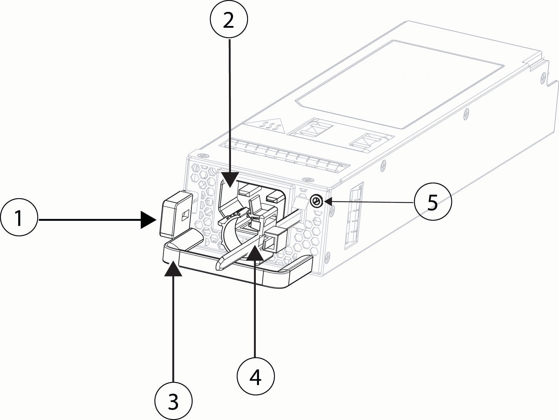
Figure 15. AC power supply module
AC power supply module

1

Release tab

2

Power cord connector

3

Handle

4

Cord retention mechanism

5

Bicolor power supply LED:

  • Green—Active mode

  • Green, flashing—Standby mode

  • Green, flashing—Boot loading process

  • Amber—No AC power, but the other power supply module in the system is operating

  • Amber—Power supply module fault

  • Off—No input power

—

Table 2. AC power supply module hardware specifications

Specification

4215

4225

4245

Dimensions

1.575 x 2.657 x 9.92 inches (40.0 x 67.5 x 252 mm)

Hot-swappable

Yes

Redundancy

1+1 maximum in parallel

Input voltage

100 to 120 VAC (low line)

200 to 240 VAC (high line)

Only 200 to 240 VAC (high line)

Input current (maximum)

14 A at 100 VAC or 13 A at 200 VAC

Input voltage frequency

50 to 60 Hz (nominal)

Output main voltage at current

12 V +/- 5% at 100 A (low line)

12 V +/- 5% at 158 A (high line)

Output standby voltage at current

12 V at 2.5 A

Output power

1200 W (low line)

1900 W (high line)

Energy efficiency

> 90% (platinum)

Temperature (operating)

100% load at 6000 ft (1828.8 m): 23 to 113 °F (-5 to 45°C)

100% load at 10000 ft (3000 m): 23 to 95°F (-5 to 35°C)

Temperature (nonoperating)

-40 to 158°F (-40 to 70°C)

Altitude (nonoperating)

-1000 to 40000 ft (-305 to 12200 m)

Humidity (operating and nonoperating)

5 to 90% (noncondensing)

DC power supply

The dual power supply modules can supply up to 1500-W power across the input voltage range (-48 VDC to -60 VDC). The load is shared when both power supply modules are plugged in and running at the same time.


Note


The system does not consume more than the capacity of one power supply module, so it always operates in full redundancy mode when two power supply modules are installed.


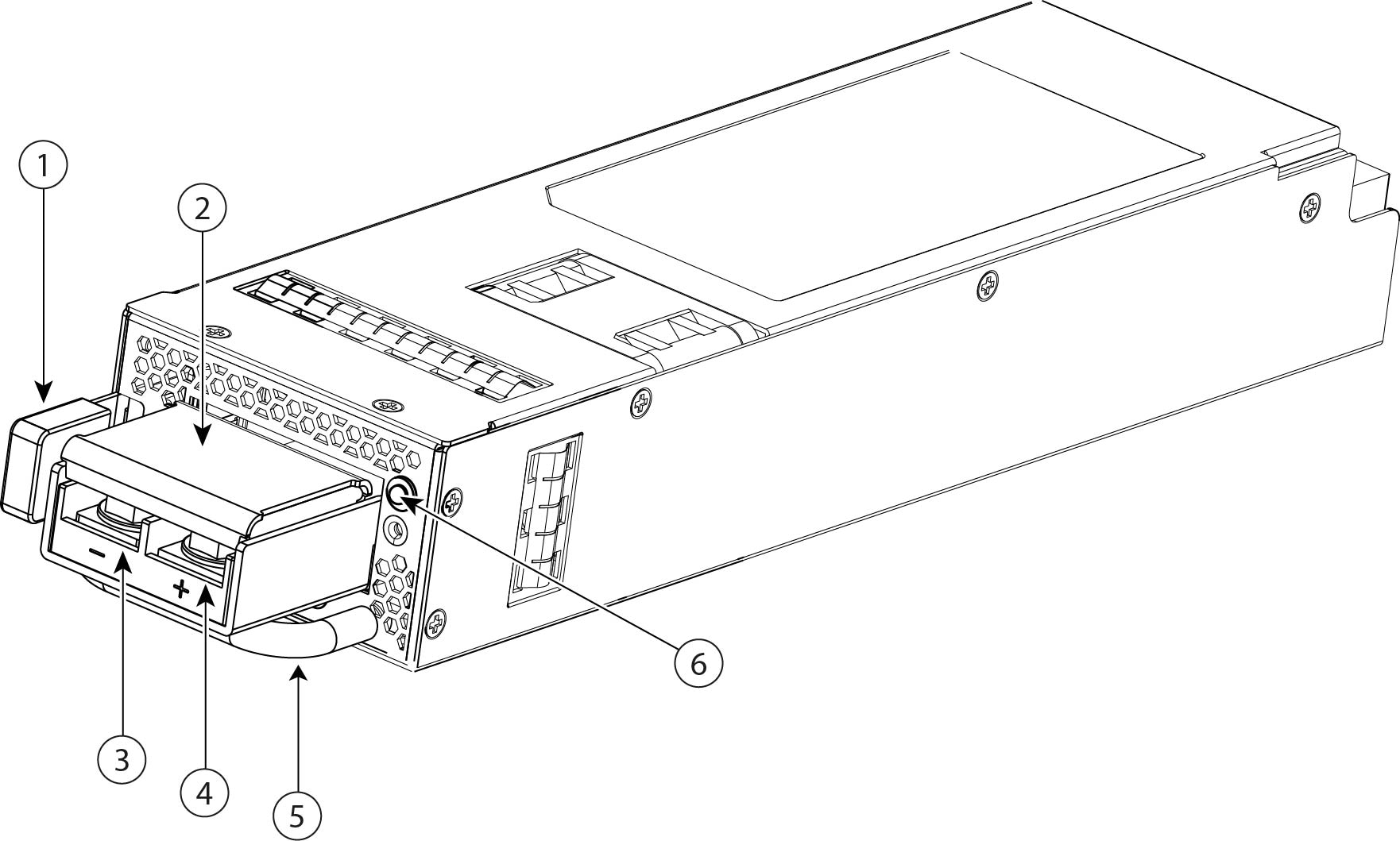
Figure 16. DC power supply module
DC power supply module

1

Release tab

2

Clear terminal lug cover

3

Left negative (-) lug terminal

4

Right positive (+) lug terminal

5

Handle

6

Bicolor power supply LED:

  • Green—Active mode

  • Green, flashing—Standby mode

  • Green, flashing—Boot loading process

  • Amber—No DC input power, but the other power supply module in the system is operating

  • Amber—Power supply module fault

  • Off—No input power

The following table lists the hardware specifiation for the DC power supply module.

Table 3. DC power supply module hardware dpecifications

Specification

4215, 4225, and 4245

Dimensions

1.575 x 2.657 x 9.92 inches (40.0 x 67.5 x 252 mm)

Hot-swappable

Yes

Redundancy

1+1 with dual power supply modules

Input voltage

-48 to -60 VDC

Input current (maximum)

< 37 A at -48 V

Input voltage frequency

N/A

Output main voltage at current

12 V at 125 A

Output standby voltage at current

12 V at 2.5 A

Output power

1500 W

Energy efficiency

> 90% at 50% load

Temperature (operating)

100% load at 6000 ft (1828.8 m): 23 to 113 °F (-5 to 45°C)

100% load at 10000 ft (3000 m): 23 to 95°F (-5 to 35°C)

Temperature (nonoperating)

-40 to 158°F (-40 to 70°C)

Altitude (nonoperating)

-1000 to 40000 ft (-305 to 12200 m)

Humidity (operating and nonoperating)

5 to 90% (noncondensing)

Dual fan modules

The Secure Firewall 4200 has three dual fan modules. There are two fans per module and each fan has dual rotors. When one fan fails, the other dual fan modules spin at maximum speed so that the system continues to function. The dual fan modules are hot-swappable and installed in the rear of the chassis.

The fan module has one two-color LED, which is located on the upper left corner of the fan. The following figure shows the location of the fan LED on the fan module.

Figure 17. Fan LED
Fan LED

1

Two-color LED:

  • Off—No power or the system is powering up.

  • Green—Fans are running normally. It may take up to one minute for the LED status to turn green after power is on.

  • Amber, flashing—One or more fan rotor RPMs is not normal. Immediate attention is required.

  • Amber—One or more fan rotors have failed. The system can continue to operate normally, but fan service is required.

SSDs

The Secure Firewall 4200 has two SSD slots that each hold one NVMe 1.8-TB SSD. By default the Secure Firewall 4200 ships with two 1.8-TB SSDs installed in slot 1 and slot 2. Software RAID1 is shipped already configured.

Hot swapping is supported. You can swap SSDs without powering off the chassis. However, before hot swapping SSDs you must issue the raid remove-secure local-disk 1|2 command to prepare the SSD for removal. This command preserves the data on the SSD. After you remove and replace the SSD, you must add it again to the RAID1 configuration using the raid add local-disk 1|2 command. See the configuration guide for your software for the procedures for removing and adding an SSD from the RAID1 configuration.


Caution


The raid remove-secure local disk command securely erases the specified SSD data.


Caution


You cannot swap SSDs between different platforms. For example, you cannot use a 3100 series SSD in a 4200 series model.


The SSD drive identifiers are disk0: and disk1:.

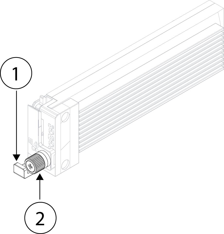
Figure 18. SSD
SSD

1

SSD release tab

Captive screw

Supported transceivers

The SFP/SFP+/QSFP+ transceiver is a bidirectional device with a transmitter and receiver in the same physical package. It is a hot-swappable optical or electrical (copper) interface that plugs into the SFP/SFP+/QSFP+ ports on the fixed ports and the network module ports, and provides Ethernet connectivity.


Note


When using fiber-based optics, make sure that the same SFP type is used on both sides of the cable because speed is not negotiated when using SFP transceivers. This is true for both copper SFPs (the exception being that the GLC-T RJ45-based copper SFPs can negotiate speed) and fiber SFPs. If a port is configured for sfp-detect, then the software configures the port’s speed to match the speed capability of the SFP. For dual-rate SFPs, when sfp-detect is configured, the port is always configured for the highest supported speed of the port. For example, a port that has a 10/25-Gbps SFP installed is configured to operate at 25 Gbps when sfp-detect is configured.


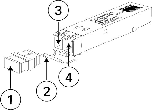
Figure 19. SFP transceiver
SFP transceiver

1

Dust plug

2

Bail clasp

3

Receive optical bore

4

Transmit optical bore

Safety warnings

Take note of the following warnings:


Warning


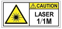
Statement 1055—Class 1/1M Laser

Invisible laser radiation is present. Do not expose to users of telescopic optics. This applies to Class 1/1M laser products.


Warning


Statement 1056—Unterminated Fiber Cable

Invisible laser radiation may be emitted from the end of the unterminated fiber cable or connector. Do not view directly with optical instruments. Viewing the laser output with certain optical instruments, for example, eye loupes, magnifiers, and microscopes, within a distance of 100 mm, may pose an eye hazard.


Warning


Statement 1057—Hazardous Radiation Exposure

Use of controls, adjustments, or performance of procedures other than those specified may result in hazardous radiation exposure.


Warning


Use appropriate ESD procedures when inserting the transceiver. Avoid touching the contacts at the rear, and keep the contacts and ports free of dust and dirt. Keep unused transceivers in the ESD packing that they were shipped in.


Caution


Although non-Cisco SFPs are allowed, we do not recommend using them because they have not been tested and validated by Cisco. Cisco TAC may refuse support for any interoperability problems that result from using an untested third-party SFP transceiver.


The following table lists the SFPs that are supported on the Secure Firewall 4215, 4225, and 4245 fixed ports.

Table 4. FPR4215, FPR4225, and FPR4245 fixed ports

Port type

Transceiver PID

First supported release

Fixed SFP/SFP+/SFP28 ports

  • GLC-TE

  • GLC-SX-MMD

  • GLC-LH-SMD

  • GLC-EX-SMD

  • GLC-ZX-SMD

  • SFP-10G-SR

  • SFP-10G-SR-S

  • SFP-10G-LR

  • SFP-10G-LR-S

  • SFP-10G-ER

  • SFP-10G-ER-S

  • SFP-H10GB-CUxM

  • SFP-H10GB-ACUxM

  • SFP-10G-AOCxM

Threat Defense 7.4/ASA 9.20

  • SFP-10G-T-X

Theat Defense 7.6/ASA 9.22

  • SFP-25G-SR-S

  • SFP-10/25G-CSR-S

  • SFP-10/25G-LR-S

  • SFP-H25-CUxM

  • SFP-25G-AOCxM

Threat Defense 7.4/ASA 9.20

The following table lists the SFPs that are supported on the Secure Firewall 4215, 4225, and 4245 management ports.

Table 5. FPR4215, FPR4225, and FPR4245 management ports

Port type

Transceiver PID

First supported release

Management SFP/SFP+/SFP28 ports

  • GLC-TE

  • GLC-SX-MMD

  • GLC-LH-SMD

  • GLC-EX-SMD

  • GLC-ZX-SMD

  • SFP-10G-SR

  • SFP-10G-SR-S

  • SFP-10G-LR

  • SFP-10G-LR-S

  • SFP-10G-ER

  • SFP-10G-ER-S

  • SFP-H10GB-CUxM

  • SFP-H10GB-ACUxM

  • SFP-10G-AOCxM

Threat Defense 7.4/ASA 9.20

  • SFP-10G-T-X

Theat Defense 7.6/ASA 9.22

  • SFP-25G-SR-S

  • SFP-10/25G-CSR-S

  • SFP-10/25G-LR-S

  • SFP-H25-CUxM

  • SFP-25G-AOCxM

Threat Defense 7.4/ASA 9.20

The following table lists the SFPs that are supported on the 8-port 10-Gbps network module.

Table 6. FPR4215, FPR4225, and FPR4245 8-port 10-Gbps network module

Port type

Transceiver PID

First supported release

FPR4K-XNM-8X10G

  • GLC-TE

  • GLC-SX-MMD

  • GLC-LH-SMD

  • GLC-EX-SMD

  • GLC-ZX-SMD

  • SFP-10G-SR

  • SFP-10G-SR-S

  • SFP-10G-LR

  • SFP-10G-LR-S

  • SFP-10G-ER

  • SFP-10G-ER-S

  • SFP-H10GB-CUxM

  • SFP-H10GB-ACUxM

  • SFP-10G-AOCxM

Threat Defense 7.4/ASA 9.20

  • SFP-10G-T-X

Threat Defense 7.6/ASA 9.22

The following table lists the SFPs that are supported on the 8-port 25-Gbps network module.

Table 7. FPR4215, FPR4225, and FPR4245 8-Port 25-Gbps network module

Port type

Transceiver PID

First supported release

FPR4K-XNM-8X25G

  • GLC-TE

  • GLC-SX-MMD

  • GLC-LH-SMD

  • GLC-EX-SMD

  • GLC-ZX-SMD

  • GLC-GE-100FX

  • SFP-10G-SR

  • SFP-10G-SR-S

  • SFP-10G-LR

  • SFP-10G-LR-S

  • SFP-10G-ER

  • SFP-10G-ER-S

  • SFP-H10GB-CUxM

  • SFP-H10GB-ACUxM

  • SFP-10G-AOCxM

Threat Defense 7.4/ASA 9.20

  • SFP-10G-T-X

Threat Defense 7.6/ASA 9.22

  • SFP-25G-SR-S

  • SFP-10/25G-CSR-S

  • SFP-10/25G-LR-S

  • SFP-H25-CUxM

  • SFP-25G-AOCxM

Threat Defense 7.4/ASA 9.20

The following table lists the SFPs that are supported on the 4-port 40-Gbps network module.

Table 8. FPR4215, FPR4225, and FPR4245 4-port 40-Gbps network module

Port Type

Transceiver PID

First supported release

FPR4K-XNM-4X40G

  • QSFP-40G-SR4

  • QSFP-40G-SR4-S

  • QSFP-40G-CSR4

  • QSFP-40G-SR-BD

  • QSFP-40G-LR4-S

  • QSFP-40G-LR4

  • WSP-Q40GLR4L

  • QSFP-H40G-CUxM

  • QSFP-4SFP10G-CUxM

  • QSFP-H40G-ACUxM

  • QSFP-4X10G-ACUxM

  • QSFP-H40G-AOCxM

  • QSFP-4X10G-AOCxM

Threat Defense 7.4/ASA 9.20

The following table lists the SFPs that are supported on the 2-port 100-Gbps network module.

Table 9. FPR4215, FPR4225, and FPR4245 2-port 100-Gbps network module

Port type

Transceiver PID

First supported release

FPR4K-XNM-2X100G

  • QSFP-100G-SR4-S

  • QSFP-100G-LR4-S

  • QSFP-40/100G-SRBD

  • QSFP-100G-AOCxM

  • QSFP-100G-CUxM

  • QSFP-4SFP25G-CUxM

  • QSFP-100G-FR-S

  • QSFP-100G-DR-S

Threat Defense 7.4/ASA 9.20

  • QSFP-100G-LR-S

  • QSFP-100G-SM-SR

  • QSFP-100G-SR1.2

Threat Defense 7.6/ASA 9.22

The following table lists the SFPs that are supported on the 4-port 200-Gbps network module.

Table 10. FPR4215, FPR4225, and FPR4245 4-port 200-Gbps network module

Port type

Transceiver PID

First supported release

FPR4K-XNM-4X200G

  • QSFP-100G-SR4-S

  • QSFP-100G-LR4-S

  • QSFP-40/100G-SRBD

  • QSFP-100G-AOCxM

  • QSFP-100G-CUxM

  • QSFP-4SFP25G-CUxM

  • QSFP-100G-FR-S

  • QSFP-100G-DR-S

Threat Defense 7.4/ASA 9.20

  • QSFP-100G-LR-S

  • QSFP-100G-SM-SR

  • QSFP-100G-SR1.2

Threat Defense 7.6/ASA 9.22

  • QSFP-200-CU3M

  • QSFP-200G-SR4-S

  • QSFP-200G-SL4-S

  • QSFP-200G-FR4-S

  • QDD-2Q200-CU3M

  • QDD-2X100-LR4-S

  • QDD-2X100-SR4-S

Threat Defense 7.7/ASA 9.23

The following table lists the SFPs that are supported on the 2-port 400-Gbps network module.

Table 11. FPR4215, FPR4225, and FPR4245 2-port 400-Gbps network module

Port type

Transceiver PID

First supported release

FPR4K-XNM-2X400G

  • QSFP-100G-SR4-S

  • QSFP-100G-LR4-S

  • QSFP-40/100G-SRBD

  • QSFP-100G-AOCxM

  • QSFP-100G-CUxM

  • QSFP-4SFP25G-CUxM

  • QSFP-100G-FR-S

  • QSFP-100G-DR-S

  • QSFP-100G-LR-S

  • QSFP-100G-SM-SR

  • QSFP-100G-SR1.2

Threat Defense 7.6/ASA 9.22

  • QSFP-200-CU3M

  • QSFP-200G-SR4-S

  • QSFP-200G-SL4-S

  • QSFP-200G-FR4-S

  • QDD-2Q200-CU3M

  • QDD-2X100-LR4-S

  • QDD-2X100-SR4-S

Threat Defense 7.7/ASA 9.23

  • QDD-400G-DR4-S

  • QDD-4x100G-FR-S

  • QDD-4x100G-LR-S

  • QDD-400G-SR4.2-BD

  • QDD-400G-FR4-S

  • QDD-400G-LR4-S

  • QDD-400-CUxM

Threat Defense 7.6/ASA 9.22

  • QDD-400-AOCxM

  • QDD-2X100-LR4-S

  • QDD-2X100-SR4-S

Threat Defense 7.7/ASA 9.23

Hardware specifications

The following table contains hardware specifications for the Secure Firewall 4200.

Table 12. Secure Firewall 4200 hardware specifications

Specification

4215

4225

4245

Chassis dimensions (H x W x D)

1.73 x 19.0 x 32.0 inches (4.39 x 48.26 x 81.28 cm)

Network module dimensions (H x W x D)

1.41 in (3.58 cm)

3.66 in (9.3 cm)

9.94 in (25.25 cm)

Chassis weight

(2 power supplies, 2 network modules, 3 fan modules)

43 lb (19.5 kg)

43 lb (19.5 kg)

46 lb (20.8 kg)

Chassis weight

(no powers supplies, no network modules, no fan modules)

33 lb (15 kg)

33 lb (15 kg)

36 lb (16.3 kg)

System power

770 W

870 W

1380 W

Temperature

Operating: 32 to 104°F (-0 to 40°C)

Nonoperating: -40 to 149°F (-40 to 65°C) maximum altitude is 40,000 ft

Humidity

Operating: 5 to 90% noncondensing

Nonoperating: 5 to 90% noncondensing

Altitude

Operating: 0 to 10,000 ft (0 to 1829 m) maximum

Nonoperating: 40,000 ft (12,192 m) maximum

Sound pressure

<=78 dBA (typical)

<= 4 dBA (maximum)

Sound power

<=87 dB (typical)

<=92 dB (maximum)

NEBS

Operating altitude: 0 to 13,000 ft (3960 m)

Operating temperature:

  • Long Term: 32 to 113°F (0 to 45°C) up to 6000 ft (1829 m)

  • Long Term: 32 to 95°F (0 to 35°C) 6000-13000 ft (1829-3964 m)

  • Short Term: 32 to 122°F (-5 to 50°C) up to 6000 ft (1829 m)

Note


Secure Firewall 4200 NEBS compliance applies only to the 4215.

Product ID numbers

The Secure Firewall 4200 uses specific Product IDs (PIDs) to identify its chassis, field-replaceable accessories, and network modules. You can verify the components currently installed in your system by running the show inventory command within the Cisco Secure Firewall Threat Defense or ASA command-line interfaces.

The following table lists the PIDs associated with the Secure Firewall 4200. All of the PIDs in the table are field-replaceable.

Table 13. Secure Firewall 4200 PIDs

PID

Description

Chassis

FPR4215-ASA-K9

Cisco Secure Firewall 4215 ASA chassis 1 RU

FPR4225-ASA-K9

Cisco Secure Firewall 4225 ASA chassis 1 RU

FPR4245-ASA-K9

Cisco Secure Firewall 4245 ASA chassis 1 RU

FPR4215-NGFW-K9

Cisco Secure Firewall 4215 next generation firewall chassis 1 RU

FPR4225-NGFW-K9

Cisco Secure Firewall 4225 next generation firewall chassis 1 RU

FPR4245-NGFW-K9

Cisco Secure Firewall 4245 next generation firewall chassis 1 RU

FPR4215-NGIPS-K9

Cisco Secure Firewall 4215 next generation firewall chassis 1 RU

FPR4225-NGIPS-K9

Cisco Secure Firewall 4225 next generation firewall chassis 1 RU

FPR4245-NGIPS-K9

Cisco Secure Firewall 4245 next generation firewall chassis 1 RU

Accessories

FPR4200-ACY-KIT=

Accessory kit (spare)

FPR4200-PWR-AC

1900-W AC power supply module

FPR4200-PWR-AC=

1900-W AC power supply module (spare)

FPR4200-PWR-DC

1500-W DC power supply module

FPR4200-PWR-DC=

1500-W DC power supply module (spare)

FPR4200-PSU-BLANK

Power supply blank slot cover

FPR4200-PSU-BLANK=

Power supply blank slot cover (spare)

FPR4200-SSD1800

1800 GB SSD

FPR4200-SSD1800=

1800 GB SSD (spare)

FPR4200-FAN

Dual fan module

FPR4200-FAN=

Dual fan module (spare)

FPR4200-SLD-RAILS

Slide rail kit

FPR4200-SLD-RAILS=

Slide rail kit (spare)

FPR4200-CBL-MGMT

Cable management brackets

FPR4200-CBL-MGMT=

Cable management brackets (spare)

FPR4200-FIPS-KIT

FIPS opacity shield; covers the serial number on the chassis

FPR4200-FIPS-KIT=

FIPS opacity shield; covers the serial number on the chassis (spare)

Network Modules

FPR4K-XNM-6X1SXF

6-port 1-Gbps SFP hardware bypass network module, SX multimode

FPR4K-XNM-6X1SXF=

6-port 1-Gbps SFP hardware bypass network module, SX multimode (spare)

FPR4K-XNM-6X10SRF

6-port 10-Gbps SFP hardware bypass network module, SR multimode

FPR4K-XNM-6X10SRF=

6-port 10-Gbps SFP hardware bypass network module, SR multimode (spare)

FPR4K-XNM-6X10LRF

6-port 10-Gbps SFP hardware bypass network module, LR single mode

FPR4K-XNM-6X10LRF=

6-port 10-Gbps SFP hardware bypass network module, LR single mode (spare))

FPR4K-XNM-6X25SRF

6-port 25-Gbps SFP hardware bypass network module, SR multimode

FPR4K-XNM-6X25SRF=

6-port 25-Gbps SFP hardware bypass network module, SR multimode (spare)

FPR4K-XNM-6X25LRF

6-port 25-Gbps SFP hardware bypass network module, LR single mode

FPR4K-XNM-6X25LRF=

6-port 25-Gbps SFP hardware bypass network module, LR single mode (spare)

FPR4K-XNM-8X1GF

8-port 10/100/1000Base-10 hardware bypass network module

FPR4K-XNM-8X1GF=

8-port 10/100/1000Base-10 hardware bypass network module (spare)

FPR4K-XNM-8X10G

8-port 1/10-Gbps SFP+ network module

FPR4K-XNM-8X10G=

8-port 1/10-Gbps SFP+ network module (spare)

FPR4K-XNM-8X25G

8-port 1/10/25-Gbps ZSFP network module

FPR4K-XNM-8X25G=

8-port 1/10/25-Gbps ZSFP network module (spare)

FPR4K-XNM-4X40G

4-port 40-Gbps QSFP+ network module

FPR4K-XNM-4X40G=

4-port 40-Gbps QSFP+ network module

FPR4K-XNM-2X100G

2-port 100-Gbps QSFP+

FPR4K-XNM-2X100G=

2-port 100-Gbps QSFP+ (spare)

FPR4K-XNM-4X200G

4-port 40/100/200-Gbps QSFP+

FPR4K-XNM-4X200G=

4-port 40/100/200-Gbps QSFP+ (spare)

FPR-X-NM-2X400G

2-port 200/400-Gbps QSFP-DD

FPR-X-NM-2X400G=

2-port 200/400-Gbps QSFP-DD (spare)

CSF6K-XNM-2X100SRF

2-port 100-Gbps hardware bypass network module, SR-multimode

CSF6K-XNM-2X100SRF=

2-port 100-Gbps hardware bypass network module, SR-multimode (spare)

FPR4200-NM-BLANK

Network module blank slot cover

FPR4200-NM-BLANK=

Network module blank slot cover (spare)

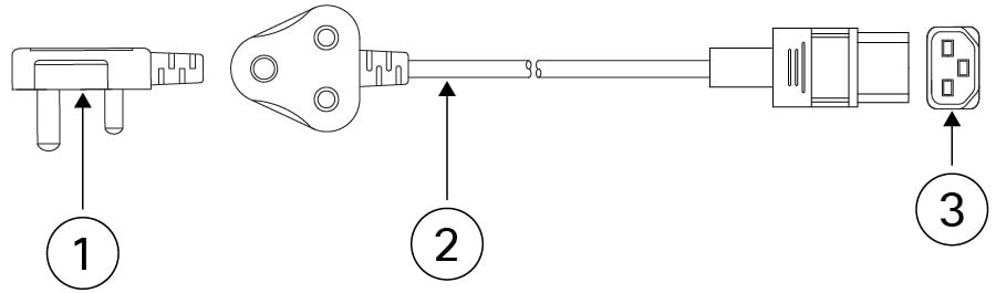
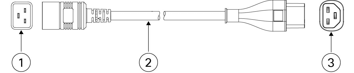
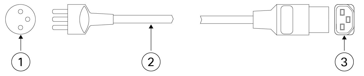
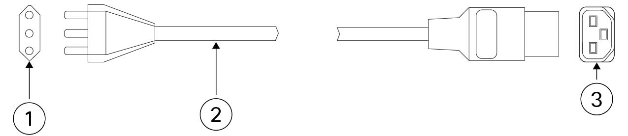
Power cord specifications

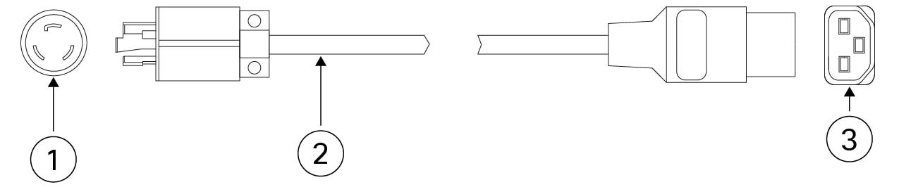
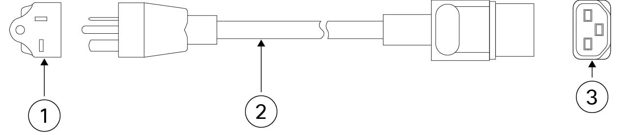
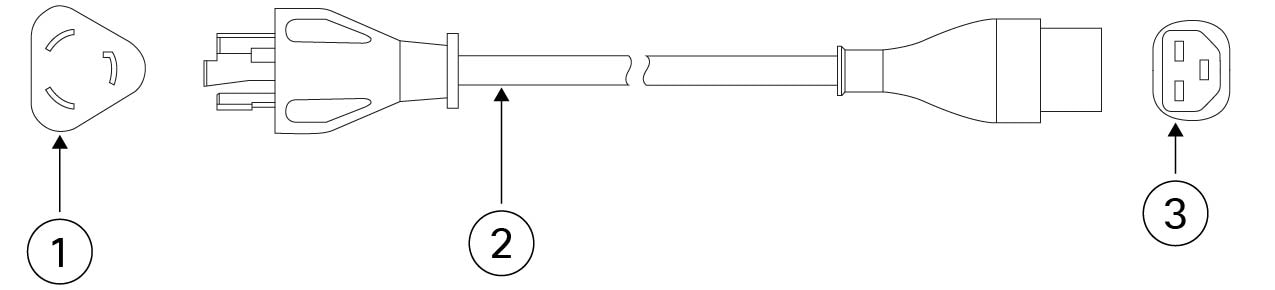
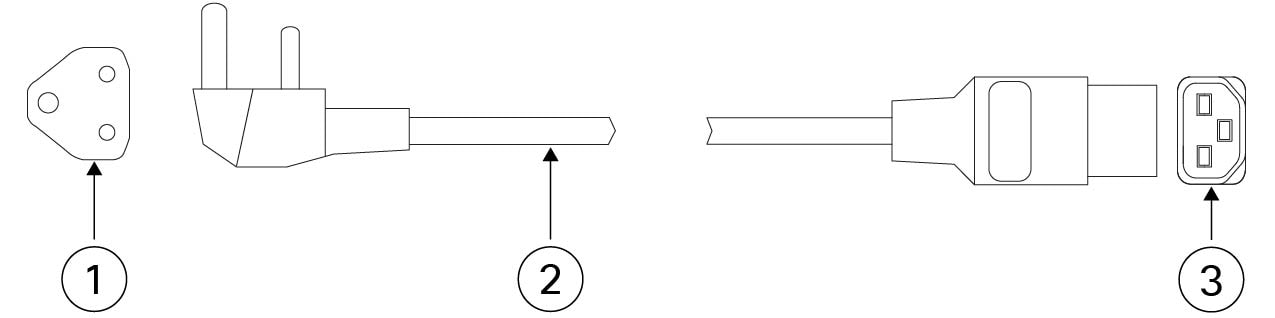
Each power supply has a separate power cord. Standard power cords or jumper power cords are available for connection to the secure firewall. The jumper power cords for use in racks are available as an optional alternative to the standard power cords. If you do not order the optional power cord with the system, you are responsible for selecting the appropriate power cord for the product. Using a incompatible power cord with this product may result in electrical safety hazard.


Note


Only the approved power cords or jumper power cords provided with the Secure 4200 are supported.


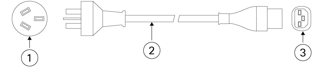
The following power cords are supported.

Figure 20. Argentina
Argentina
PID: PWR-CAB-AC-ARG Part number: 37-1711-01

1

Plug: IRAM 2073

2

Cord set rating: 20 A, 250 V

3

Connector: IEC 60320/C21

Cord length: 14 ft (4.25 m)

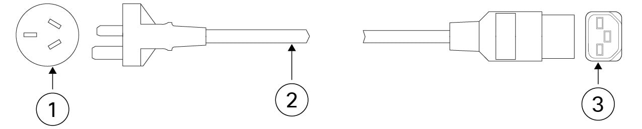
Figure 21. Australia
Australia
PID: PWR-CAB-AC-AUS Part number: 72-5201-01

1

Plug: A.S./NZS 3112

2

Cord set rating: 15 A, 250 V

3

Connector: IEC 60320/C21

Cord length: 14 ft (4.3 m)

Figure 22. Brazil
Brazil
PID: PWR-CAB-AC-BRA Part number: 72-5208-01

1

Plug: NBR 14136

2

Cord set rating: 16 A, 250 V

3

Connector: IEC 60320/C21

Cord length: 14 ft (4.3 m)

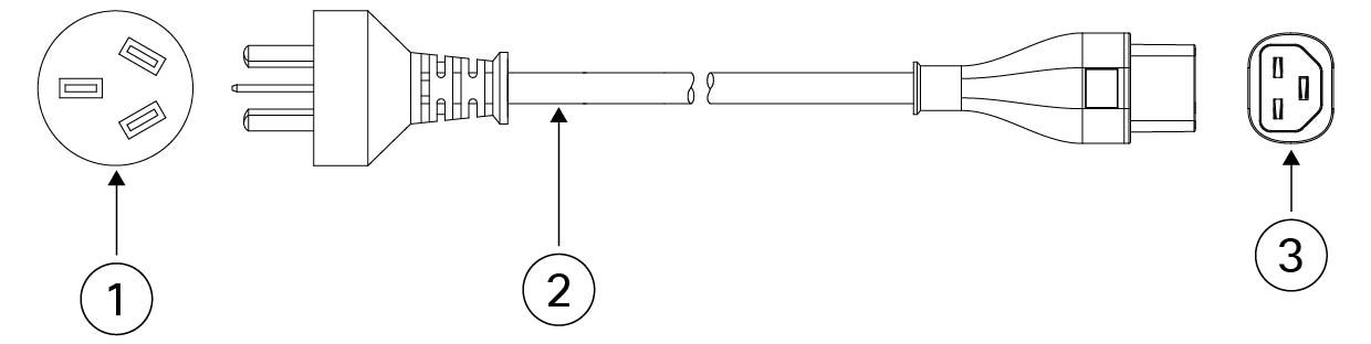
Figure 23. China
China
PID: PWR-CAB-AC-CHN Part number: 72-5207-01

1

Plug: GB16C

2

Cord set rating: 16 A, 250 V

3

Connector: IEC 60320/C21

Cord length: 14 ft (4.3 m)

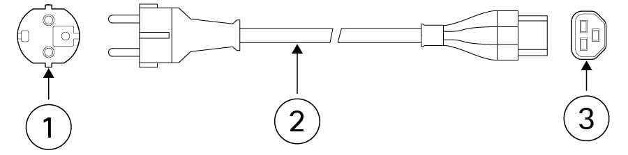
Figure 24. Europe
Europe
PID: PWR-CAB-AC-EU Part number: 37-1808-01

1

Plug: CEE 7/7

2

Cord set rating: 16 A, 250 V

3

Connector: IEC 60320/C21

Cord length: 14 ft (4.3 m)

Figure 25. India
India
PID: PWR-CAB-AC-IND Part number: 37-1857-01

1

Plug: IS 1293

2

Cord set rating: 16 A, 250 V

3

Connector: IEC 60320/C21

Cord length: 14 ft (4.3 m)

Figure 26. International
International
PID: PWR-CAB-AC-BLK Part number: 72-5595-01

1

Plug: IEC 60320/20

2

Cord set rating: 20 A, 250 V

3

Connector: IEC 60320/C21

Cord length: 14 ft (4.3 m)

Figure 27. Israel
Israel
PID: PWR-CAB-AC-ISRL Part number: 72-5206-01

1

Plug: SI-32

2

Cord set rating: 16 A, 250 V

3

Connector: IEC 60320/C21

Cord length: 14 ft (4.3 m)

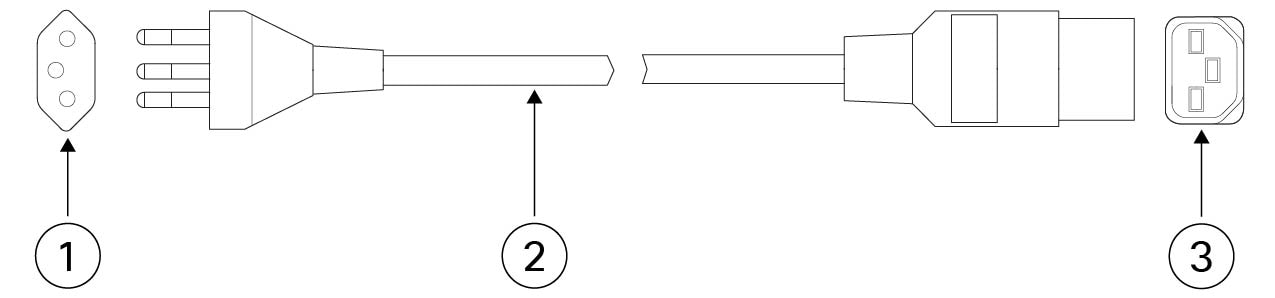
Figure 28. Italy
Italy
PID: PWR-CAB-AC-ITA Part number: 72-5203-01

1

Plug: CEI 23-50

2

Cord set rating: 16 A, 250 V

3

Connector: IEC 60320/C21

Cord length: 14 ft (4.3 m)

Figure 29. Japan
Japan
PID: PWR-CAB-AC-JPN Part number: 72-5210-01

1

Plug: NEMA L6-20

2

Cord set rating: 20 A, 250 V

3

Connector: IEC 60320/C21

Cord length: 14 ft (4.3 m)

Figure 30. Korea
Korea
PID: PWR-CAB-AC-KOR Part number: 37-1808-01

1

Plug: CEE 7/7

2

Cord set rating: 16 A, 250 V

3

Connector: IEC 60320/C21

Cord length: 14 ft (4.3 m)

Figure 31. North America
North America
PID: PWR-CAB-AC-USA520 Part number: 37-1849-01

1

Plug: NEMA 5-20P

2

Cord set rating: 20 A, 125 V

3

Connector: IEC 60320/C21

Cord length: 14 ft (4.3 m)

Figure 32. North America
North America
PID: PWR-CAB-AC-USA Part number: 72-5200-01

1

Plug: NEMA L6-20P

2

Cord set rating: 20 A, 250 V

3

Connector: IEC 60320/C21

Cord length: 14 ft (4.3 m)

Figure 33. South Africa
South Africa
PID: PWR-CAB-AC-SA Part number: 72-5204-01

1

Plug: SABS 164

2

Cord set rating: 16 A, 250 V

3

Connector: IEC 60320/C21

Cord length: 14 ft (4.3 m)

Figure 34. Switzerland
Switzerland
PID: PWR-CAB-AC-SUI Part number: 72-5209-01

1

Plug: SEV 1011

2

Cord set rating: 16 A, 250 V

3

Connector: IEC 60320/C21

Core length: 14 ft (4.3 m)

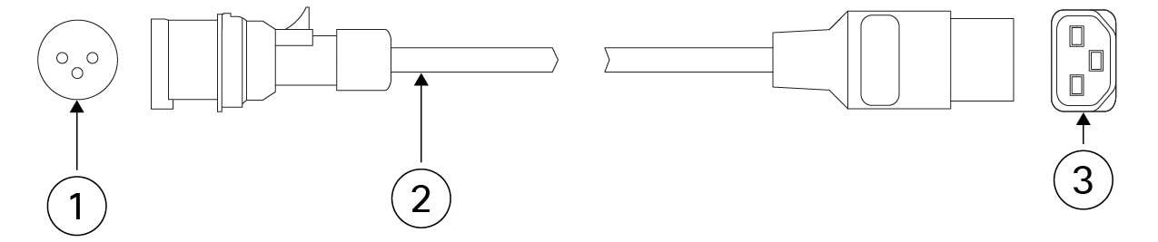
Figure 35. United Kingdom
United Kingdom
PID: PWR-CAB-AC-UK Part number: 72-5205-01

1

Plug: IEC309

2

Cord set rating: 16 A, 250 V

3

Connector: IEC 60320/C21

Length: 14 ft (4.3 m)