Installation, Maintenance, and Upgrade

Install, remove, and replace the network module

You can remove and replace the network modules (NM-2 and NM-3) in the Secure Firewall 4200. Although the hardware supports removing and replacing the network module while the system is running, the software does not currently support hot swapping. You must power down the chassis or disable the network slot to remove and replace network modules.

See the configuration guide for your operating system for the procedure for managing network modules.

This procedure describes how to install a network module into an empty slot that has never contained a network module, and how to remove an installed network module and replace it with another network module.

Procedure


Step 1

To install a network module for the first time into an empty slot, do the following:

  1. Power down the chassis by moving the power switch to the OFF position.

    See the configuration guide for your operating system for the procedure for installing a network module for the first time into an empty slot.
  2. Follow Steps 4 through 7 to install the new network module.

  3. Power on the chassis by moving the power switch to the ON position.

Step 2

To remove and replace an existing network module, do the following:

  1. Save your configuration.

  2. To replace an existing network module with the same model network module, disable the network slot. See the configuration guide for your operating system for the procedure to replace an existing network module with the same model.

  3. To replace an existing network module with a different model network module, power down the chassis by moving the power switch to the OFF position. See the configuration guide for your operating system for the procedure to replace an existing network module with a new model.

  4. Continue with Step 3.

Step 3

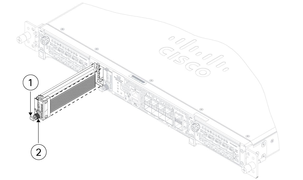
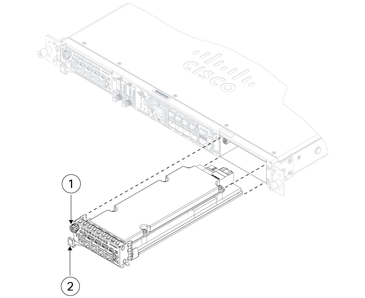
To remove a network module, loosen the captive screw on the upper left side of the network module, press the handle ejector, and pull out the handle. This mechanically ejects the network module from the slot.
Caution


The captive screw is not attached to the handle. Be sure the captive screw is completely loosened before pulling the ejector handle out. Otherwise you could damage the ejector handle as the captive screw and handle fight each other.

Figure 1. Remove the network module
Remove the network module

1

Chassis front panel

2

Captive screw

3

Ejector handle

If the slot is to remain empty, install a blank faceplate to ensure proper airflow and to keep dust out of the chassis; otherwise, install another network module.

Step 4

To replace a network module, hold the network module in front of the network module slot on the right of the chassis, press the ejector handle, and pull out the handle.

Step 5

Slide the network module into the slot, push it firmly into place, and close the handle on the front of the network module.

Step 6

Tighten the captive screw on the upper left side of the network module.

Step 7

Power on the chassis so that the new network module is recognized.


Remove and replace the SSD

The chassis supports two NVMe SSDs. The SSDs are configured for SW RAID1 support.


Caution


Hot swapping for the RAID configuration is not supported. To remove an SSD, you must remove it from the RAID configuration using the raid remove-secure local-disk 1|2 command.


Procedure


Step 1

Save your configuration.

Step 2

Remove SSD-1 or SSD-2 from the RAID1 configuration by using the raid remove-secure local-disk 1|2 command.

Step 3

To remove the SSD from the slot, face the front of the chassis, and pinch the release tab on the front of the SSD. This causes the ejector handle to spring open.

Step 4

Grasp the ejector handle to gently pull the SSD out of the chassis.

Figure 2. Remove the SSD
Remove the SSD

1

Handle

2

Captive screw

3

Chassis front panel

Step 5

To replace SSD-1 or SSD-2, hold the SSD with the ejector handle extended in front of the slot, push it in gently until it is seated, and then close the ejector handle.

Step 6

Check the SSD LED to make sure the SSD is operative.

Step 7

Add the new SSD to the RAID configuration using the raid add local-disk 1|2 command.


Remove and replace the dual fan module

You can remove and replace the dual fan modules while the chassis is running. There are three dual fan modules in the rear of the chassis. The air flow moves from front to back (I/O side to non-I/0 side).


Caution


Removing all of the dual fan modules exposes the chassis to no airflow. Replace the dual fan modules within 30 seconds after removal to avoid overheating the chassis. If you wait longer than 30 seconds, the chassis may power off automatically to prevent damage to components. The chassis does not power up and boot properly if the dual fan modules are missing.


Safety warnings

Take note of the following warnings:


Warning


Statement 1093—Avoid Sharp Edges

Risk of personal injury. Avoid sharp edges when installing or removing replaceable units.


Procedure


Step 1

Have the dual fan module ready for immediate insertion and near the chassis so that you can reinstall it within 30 seconds.

Step 2

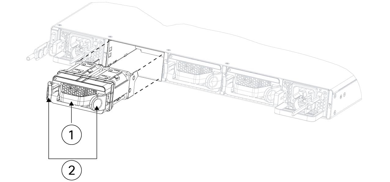
To remove a fan module, face the rear of the chassis, and press the squeeze tabs on the sides of the fan module to loosen it from the chassis.

Step 3

Grasp the handle and pull the fan module out of the chassis.

Figure 3. Remove the dual fan module
Remove the dual fan module

1

Handle

2

Squeeze tabs

3

Chassi rear panel

Step 4

To replace a fan module, hold the fan module in front of the fan slot.

Step 5

Press the squeeze tabs on the sides of the fan module and push the it into the chassis.

Step 6

Grasp the handle and push until the fan module is properly seated.

If the system is powered on, listen for the fans. You should immediately hear the fans operating. If you do not hear the fans, make sure the fan module is inserted completely into the chassis and the faceplate is flush with the outside surface of the chassis.

Step 7

Verify that the fan is operational by checking the fan module LED.


Remove and Replace the AC power supply module

Power supply modules are hot-swappable. You can remove and replace power supply modules while the system is running.

Safety warnings

Take note of the following warnings:


Warning


Statement 1005—Circuit Breaker

This product relies on the building's installation for short-circuit (overcurrent) protection. Ensure that the protective device is rated not greater than:

AC 20 A

DC 50 A


Warning


Statement 1015—Battery Handling

To reduce risk of fire, explosion or leakage of flammable liquid or gas:

  • Replace the battery only with the same or equivalent type recommended by the manufacturer.

  • Do not dismantle, crush, puncture, use sharp tool to remove, short external contacts, or dispose of in fire.

  • Do not use if battery is warped or swollen.

  • Do not store or use battery in a temperature > 60° C.

  • Do not store or use battery in low air pressure environment < 69.7 kPa.


Warning


Statement 1046—Installing or Replacing the Unit

To reduce risk of electric shock, when installing or replacing the unit, the ground connection must always be made first and disconnected last.

If your unit has modules, secure them with the provided screws.


Procedure


Step 1

Unplug the power supply cable before removing the power supply module. You cannot disengage the power supply module release tab without first removing the cable.

Step 2

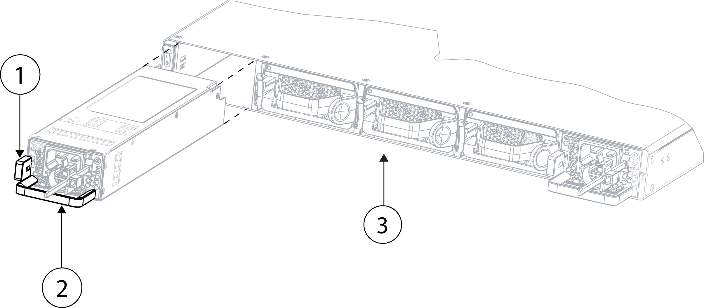
To remove a power supply module, face the back of the chassis and grasp the handle.

Step 3

Press the release tab toward the left to disengage the power supply. The release tab is found on the right side of the power supply.

Step 4

Place your other hand under the power supply module to support it while you slide it out of the chassis.

Figure 4. Remove the power supply module
Remove the power supply module

1

Release tab

2

Power supply handle

3

Chassis rear panel

If the slot is to remain empty, install a blank faceplate to ensure proper airflow; otherwise, install another power supply module.

Step 5

To replace a power supply module, hold the power supply module with both hands and slide it into the power supply module bay.

Step 6

Push in the power supply module gently until you hear the release tab engage and the power supply is seated.

Step 7

Plug in the power supply cable.

Step 8

Check the LED on the power supply to make sure the power supply is operative.


Install the DC power supply module


Note


Replace power supplies immediately. Power supply module blanks are not available.


This procedure describes how to install and connect the DC power supply module in the chassis.

Safety warnings

Take note of the following power and component removal safety warnings:


Warning


Statement 1003—DC Power Disconnection

To reduce risk of electric shock or personal injury, disconnect DC power before removing or replacing components or performing upgrades.


Warning


Statement 1005—Circuit Breaker

This product relies on the building’s installation for short-circuit (overcurrent) protection. To reduce risk of electric shock or fire, ensure that the protective device is rated not greater than:

AC: 20A

DC: 50A


Warning


Statement 1022—Disconnect Device

To reduce the risk of electric shock and fire, a readily accessible disconnect device must be incorporated in the fixed wiring.


Warning


Statement 1028—More Than One Power Supply

This unit might have more than one power supply connection. To reduce risk of electric shock, remove all connections to de-energize the unit.


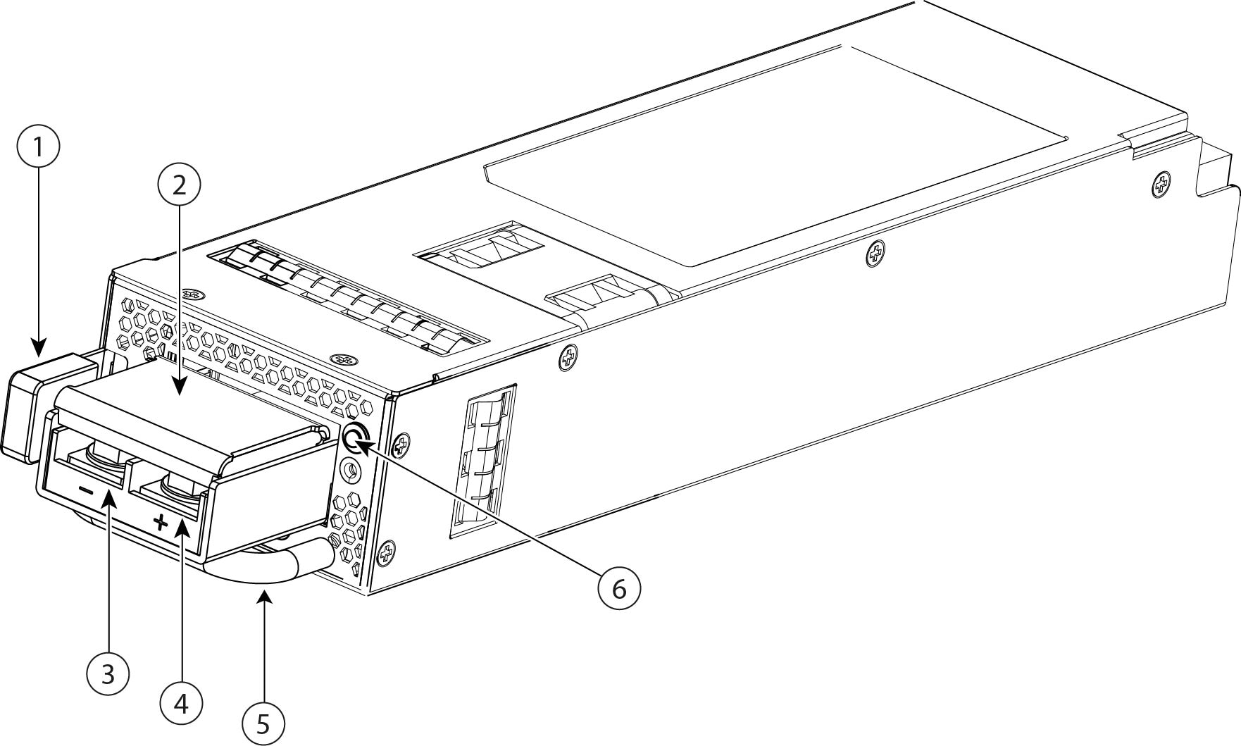
The 1500-W DC power supply module has high reliability and high efficiency with 12 VDC and 12 V standby outputs. Standby output is always present when input power is provided

Figure 5. DC power supply module
DC power supply module

1

Release tab

2

Clear terminal lug cover

3

Left negative (-) lug terminal

4

Right positive (+) lug terminal

5

Handle

6

Bicolor power supply LED:

  • Green—Active mode

  • Green, flashing—Standby mode

  • Green, flashing—Boot loading process

  • Amber—No DC input power, but the other power supply module in the system is operating

  • Amber—Power supply module fault

  • Off—No input power

Before you begin

You need the following to install the DC power supply module:

  • 10-mm socket wrench

  • Crimping tool

  • Torque wrench; the recommended Torque setting is 5±1 N.m.

  • #8 AWG to #6 AWG wire gauge

  • Two 2-hole barrel terminal lugs (part number LCD6-14 AL or an equivalent part)


    Note


    You must procure DC power cords based on the recommended wire gauge of #8 AWG to #6 AWG and the recommended two-hole barrel terminal lugs.


Procedure


Step 1

Make sure the chassis grounded before connecting the DC power supply.

Step 2

Verify that the power is off to the DC circuit on the power supply module that you are installing.

Caution


Make sure that all site power and grounding requirements have been met.

Step 3

Lift the clear terminal lug cover to access the DC terminal lugs (see figure above).

Step 4

Using the 10-mm socket wrench, unscrew the two lug nuts.

Step 5

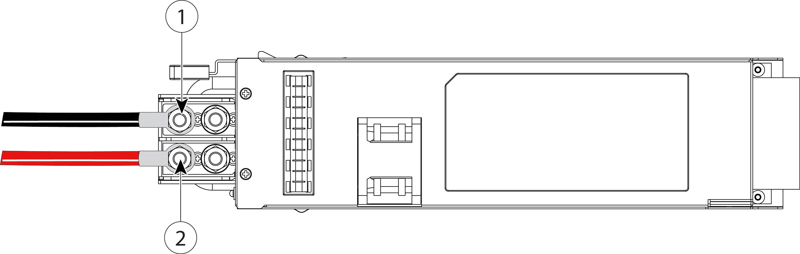
Attach the black cable to the first terminal lug (-) on the left (negative) of the power supply module terminal block.

Figure 6. Connect the cables to the terminal lugs
Connect the cables to the terminal lugs

1

Connect black cable to negative (-) terminal lug

2

Connect red cable to the positive (+) terminal lug

Step 6

Attach the red cable to the first terminal lug on the right (+) (positive) side of the power supply module terminal block.

Step 7

Using the wrench, tighten the lug nuts to secure the cables.

Caution


Do not over torque the terminal block captive screws. Make sure that the connection is snug, but the wire is not crushed. Verify by tugging lightly on each wire to make sure they do not move. The recommended Torque setting is 5±1 N.m.

Step 8

Replace the clear terminal lug cover over the terminal lugs.

This cover should always be in place when power is applied to the terminals.

Step 9

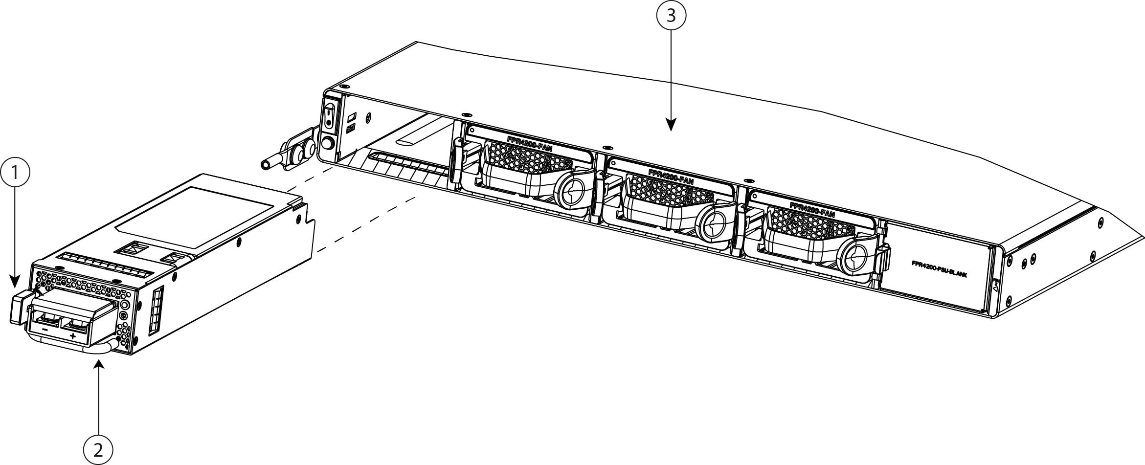
Support the DC power supply module with one hand while holding it by the handle with the other hand. Slide it into the power supply module bay and press the release tab on the left side of the power supply module until it clicks (black and red cables not shown in figure below).

Figure 7. Install the DC power supply module in the chassis
Install the DC power supply module in the chassis

1

Release tab

2

Handle

3

Chassis rear panel

Step 10

Set the DC disconnect switch in the circuit to ON.

Caution


In a system with multiple power supply modules, connect each power supply module to a separate DC power source. In the event of a power source failure, if the second source is still available, it can maintain system operation.

Step 11

Verify power supply module operation by checking the power supply LED on the front of the chassis.


Install the FIPS opacity shield


Caution


This procedure should be performed only by the Crypto Officer (CO).


Note


Because the FIPS opacity shield covers the serial number on the chassis, the CO should copy the serial number and store it in a secure place. The serial number is needed when you call Cisco TAC.


You need the following to install the FIPS opacity shield:

  • #1 Phillips screwdriver

  • The following items from the FIPS opacity shield kit:

    • One FIPS opacity shield

    • Four 8-32 x 0.375-inch Phillips screws used to attach the FIPS opacity shield to the cable management brackets

    • Ten Tamper Evidence Labels (TELs)


      Note


      The TELs are made of a special thin gauge vinyl with self-adhesive backing. Once the CO attaches them on the chassis, any attempt to open the chassis damages the TELs or the chassis cover. Because the TELs have nonrepeated serial numbers, the CO can inspect them for damage and compare them against the applied serial numbers to verify whether the chassis has been tampered with. TELs with curled corners, rips, and slices indicate tampering. The word “FIPS” or “OPEN” may appear if the label has been peeled back. Cisco recommends that you inspect the TELs for tampering every 30 days.


Procedure


Step 1

Copy the serial number and store it in a secure place.

Step 2

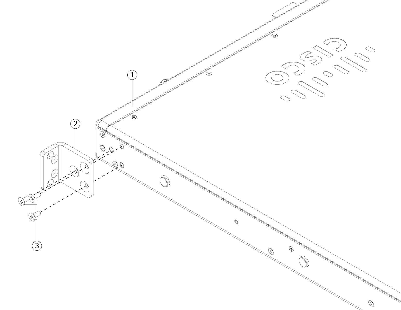
Attach the slide-rail locking brackets to each side of the chassis using the six 8-32 x 0.302-inch Phillips screws (three per side) that shipped with the brackets.

Figure 8. Attach the slide-rail locking brackets to the side of the chassis
Attach the slide-rail locking brackets to the side of the chassis

1

Chassis front panel

2

Slide-rail locking bracket

3

8-32 x 0.302-inch Phillips screws (three per side)

Step 3

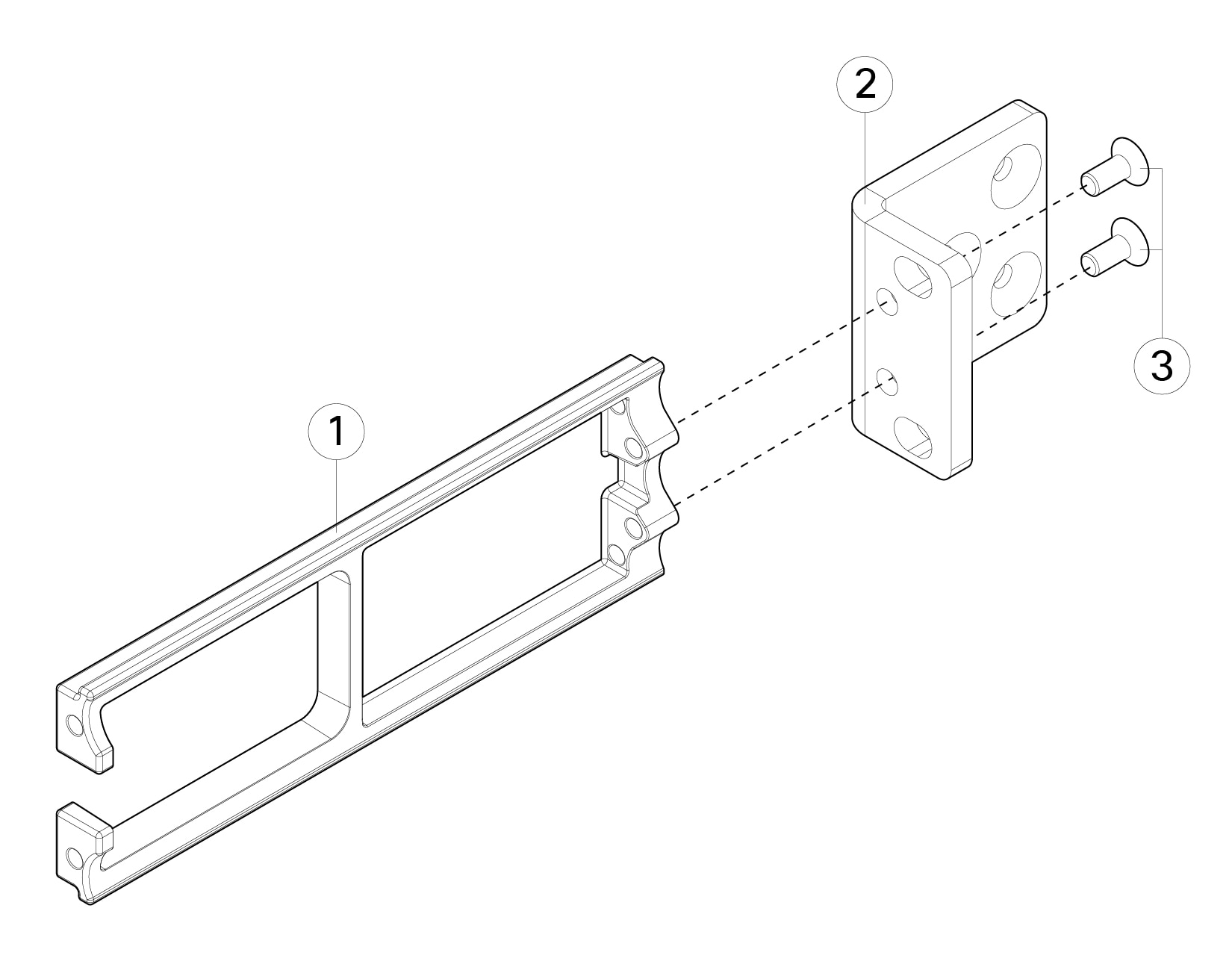
Attach the cable management bracket to the slide-rail locking bracket:

  1. Install the cable management screws into the slide-rail locking bracket.

    Caution


    Make sure the cable management bracket is oriented with the lower step on the inside so that you can slide the FIPS opacity shield over the bracket.

    Figure 9. Install the cable management brackets into the slide-rail locking brackets
    Install the cable management brackets into the slide-rail locking brackets

    1

    Step groove on the cable management bracket

    2

    Rack-mount bracket

    3

    Cable management bracket

    4

    8-32 x 0.375-inch Phillips screws (two per bracket)

  2. Install two 8-32 x 0.375 inch Phillips screws through the inside of the slide-rail locking bracket to secure the cable management bracket to slide-rail locking bracket.

Step 4

Connect the cables to the ports. Make sure the cables have enough slack to route them through the cable mounting brackets.

Note


If you are installing the FIPS opacity shield after the initial product installation, the cables are connected. If the attached cables do not have enough slack to route them through the cable mounting brackets (as shown below), you will have to turn the power off on the appliance, remove the cables, route the cables through the cable mounting brackets, reattach the cables, and continue with Step 5 below.

Note


When you toggle the power switch from ON to OFF, it takes several seconds for the system to power down. Do not remove the power cable until the power LED is off. After removing power from the chassis either by moving the power switch to OFF or unplugging the power cord, wait at least 10 seconds before turning power back ON.

Step 5

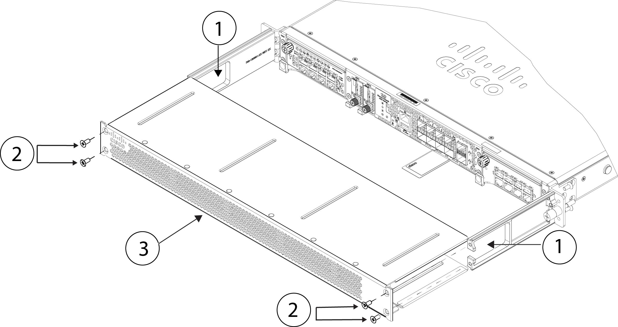
Route the cables through the openings in the cable management brackets (see figure below).

Step 6

Attach the FIPS opacity shield to the cable management brackets using the four 8-32 x 0.375 inch Phillips screws provided in the FIPS opacity shield kit.

Figure 10. Route the cables and attach the FIPS opacity shield to the cable management brackets
Route the cables and attach the FIPS opacity shield to the cable management brackets

1

Cable management brackets to route the cables through

2

8-32 x 0.375 inch-Phillips screws (two per side)

3

FIPS opacity shield

Step 7

Before you attach the TELs, clean the chassis of any grease, dirt, or oil with alcohol-based cleaning pads.

Step 8

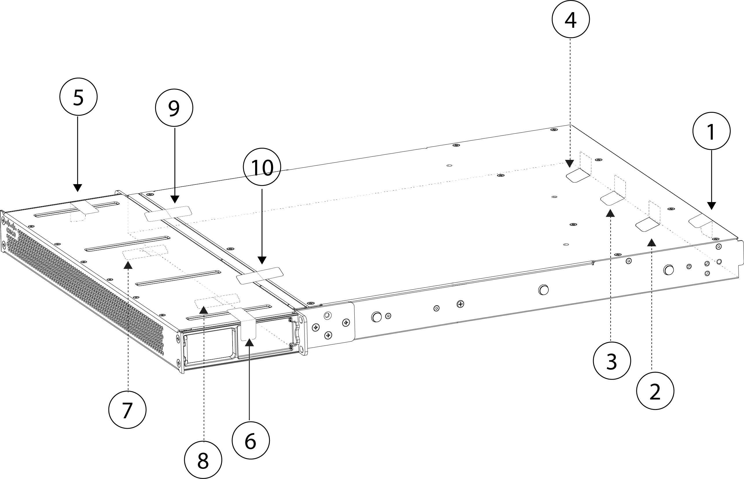
Attach the seven TELs. See the figure below for the correct placement. Allow the TELs to cure for a minimum of 12 hours.

Caution


Any deviation in the placement of the TELs means the chassis is not in FIPS mode.

Figure 11. TELs placement on the chassis
TELs placement on the chassis

1

TEL 1 on the top and rear right side of the chassis

2

TEL 2 on the bottom of the chassis towards the right side of the chassis

3

TEL 3 on the bottom of the middle of the chassis

4

TEL 4 on the bottom of the chassis towards the left side of the chassis

5

TEL 5 across the FIPS opacity shield on the left side of the chassis

6

TEL 6 across the FIPS opacity shield on the right side of the chassis

7

TEL 7 on the bottom of the chassis towards the right side

8

TEL 8 on the bottom of the chassis towards the left side

9

TEL 9 across the FIPS opacity shield and the chassis (towards the left side of the chassis)

10

TEL 10 across the FIPS opacity shield and the chassis (towards the right side of the chassis)

Step 9

Attach the power cable to the chassis and connect it to an electrical outlet.

Step 10

Press the power switch on the rear panel.

Step 11

Check the power LED on the front panel. Solid green indicates that the chassis is powered on.

Step 12

Place the chassis in FIPS mode.

See the following procedures for how to place the chassis in FIPS mode:


What to do next

See the Cisco Secure Firewall 4200 Getting Started Guide for more configuration information.