Cisco Firepower Management Center 1000, 2500, and 4500 Getting Started Guide
The Firepower Management Center (FMC) 1000, 2500, and 4500 Getting Started Guide explains FMC installation, login, setup, initial administrative settings, and configuration for your secure network. This document also describes maintenance activities such as establishing alternative means of FMC access, adding managed devices to the FMC, FMC factory reset, saving and loading configurations, erasing the hard drive, and performing an appliance shutdown or restart.
In a typical deployment on a large network, you install multiple managed devices on network segments. Each device controls, inspects, monitors, and analyzes traffic, and then reports to a managing FMC. The FMC provides a centralized management console with a web interface that you can use to perform administrative, management, analysis, and reporting tasks in service to securing your local network.
About the Firepower Management Center Models 1000, 2500, and 4500
The following topics provide information about front and rear panel features that you need to follow the instructions in this document.
Physical Interfaces
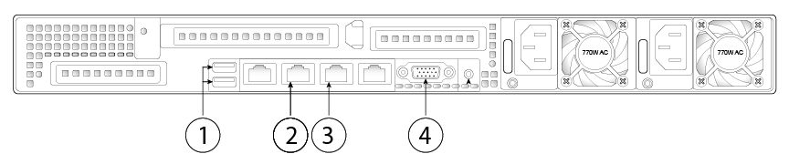
The following figure illustrates the rear panel of the FMC 1000, and identifies ports you need to follow the instructions in this document. For information on all the rear-panel ports, see the Cisco Firepower Management Center 1000, 2500, and 4500 Hardware Installation Guide.
|
1 |
2 USB keyboard ports You can connect a keyboard, and along with a monitor on the VGA port, you can access the console. |
2 |
Serial console port |
|
3 |
eth0 management interface (labeled "1") Gigabit Ethernet 10/100/1000 Mbps interface, RJ-45 eth0 is the default management interface. |
4 |
VGA interface Console message are sent to this port by default. |
 Note |
You can use Lights-Out-Management (LOM) on the default management interface (eth0) on a Serial Over LAN (SOL) connection to remotely monitor or manage the FMC system. For information about using LOM and SOL, see Set Up Lights-Out Management. |
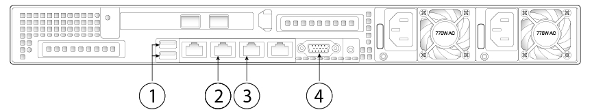
The following figure illustrates the rear panel of the FMC 2500 and 4500, and identifies ports you need to follow the instructions in this document. For information on all the rear-panel ports, see the Cisco Firepower Management Center 1000, 2500, and 4500 Hardware Installation Guide.
|
1 |
2 USB keyboard ports You can connect a keyboard, and along with a monitor on the VGA port, you can access the console. |
2 |
Serial console port |
|
3 |
eth0 management interface (labeled "1") Gigabit Ethernet 10/100/1000 Mbps interface, RJ-45 eth0 is the default management interface. |
4 |
VGA interface Console message are sent to this port by default. |
Front Panel LEDs and their States
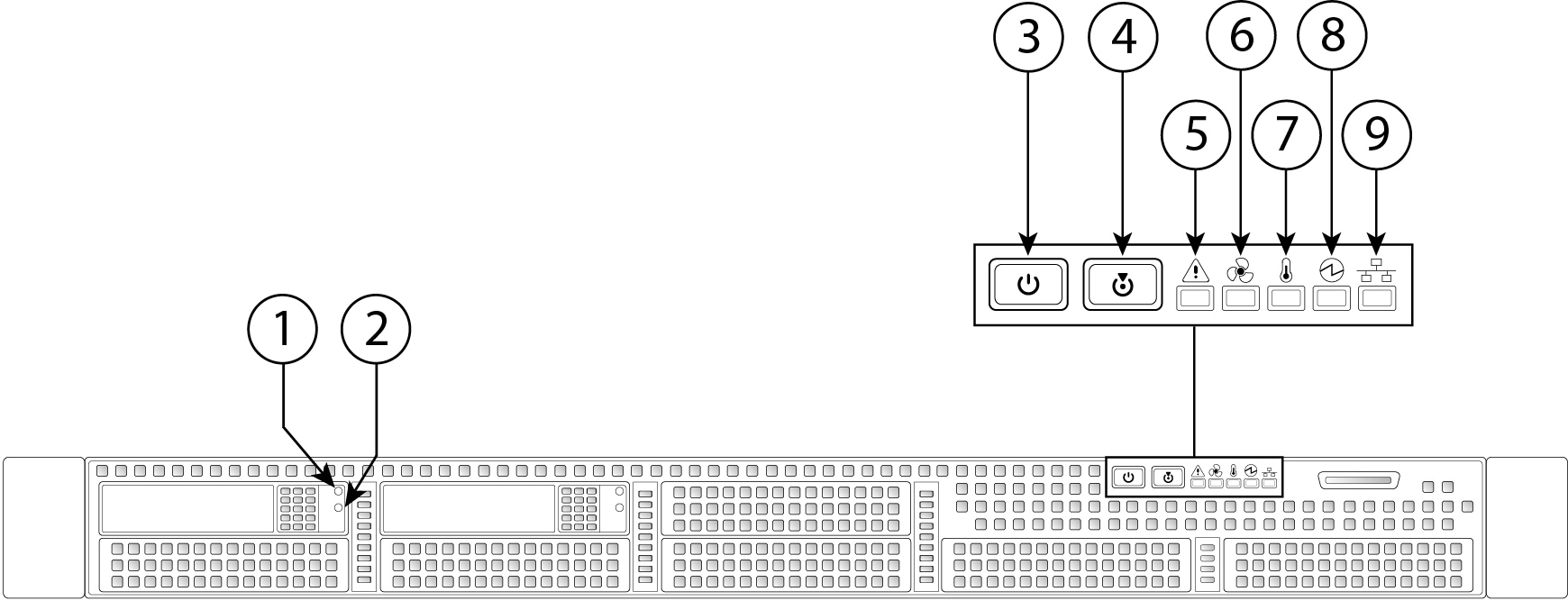
The following figure illustrates the front panel of the FMC 1000, 2500, and 4500, identifies the LED lights, and provides the information you need to determine appliance status based on the LEDs. The FMC 2500 has four SAS drives, and the FMC 4500 has six SAS drives, each with the same drive fault and drive activity LEDs as shown in the diagram. For information on all the front-panel features, see the Cisco Firepower Management Center 1000, 2500, and 4500 Hardware Installation Guide.
|
1 |
Drive fault LED
|
2 |
Drive activity LED
|
|
3 |
Power button/power status LED
|
4 |
Unit identification button/LED
|
|
5 |
System status LED
|
6 |
Fan status LED
|
|
7 |
Temperature status LED
|
8 |
Power supply status LED
|
|
9 |
Network link activity LED
|
|
Related Documentation
For detailed hardware installation instructions, see the Cisco Firepower Management Center 1000, 2500, and 4500 Hardware Installation Guide.
For a complete list of the Cisco Firepower series documentation and where to find it, see the documentation roadmap.
Access the CLI or the Linux Shell on the FMC
Accessing the FMC CLI or the Linux shell requires a different sequence of steps depending on what version the FMC is running.
 Caution |
We strongly recommend that you do not use the Linux shell unless directed by Cisco TAC or explicit instructions in the user documentation. |
Before you begin
Establish a direct physical connection with the FMC using the serial port, a keyboard and monitor, or establish an SSH session with the FMC interface.
Procedure
|
Step 1 |
Log into the FMC using the credentials for the CLI admin user. |
|
Step 2 |
Determine your next action depending on the version in use:
|
|
Step 3 |
To access the Linux shell from the FMC CLI, enter the expert command. |
Shutdown or Restart the FMC
Use the web interface to initiate an orderly shutdown or restart.
You can also shut down the FMC using the system shutdown command from the FMC CLI. (In Version 6.2, where the FMC CLI is not available, you can use the shutdown -h now command from the appliance shell.)
 Tip |
For virtual devices, see the documentation for your virtual platform. For VMware in particular, custom power options are part of VMware Tools. |
Caution |
Do not shutdown the FMC using the power button; this action can cause data loss. Using the web interface or the shutdown command prepares the system to safely power off and restart without losing configuration data. |
Procedure
|
Step 1 |
Log in to your management center, choose System ( |
|
Step 2 |
Choose one of the following:
|
Install the FMC for Versions 6.5 and Later
Follow these instructions to install the FMC that will run Versions 6.5 and later.
Review Network Deployment for Versions 6.5 and Later
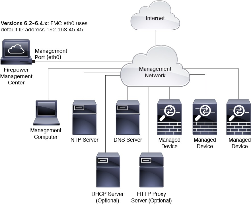
To deploy the FMC you need information about the environment within which it will operate. The following figure shows an example network configuration for a firewall deployment.

By default the FMC connects to your local management network through its management interface (eth0). Through this connection the FMC communicates with a management computer; managed devices; services such as DHCP, DNS, NTP; and the internet.
The FMC requires internet access to support Smart Licensing, Threat Intelligence Director, and malware defense services. Depending on services provided by your local management network, the FMC may also require internet access to reach an NTP or DNS server. You can configure your network to provide internet access to the FMC directly or through a firewall device.
You can upload updates for system software, as well as the Vulnerability Database (VDB), Geolocation Database (GEoDB), and intrusion rules directly to the FMC from an internet connection or from a local computer that has previously downloaded these updates from the internet.
To establish the connection between the FMC and one of its managed devices, you need the IP address of at least one of the devices: the FMC or the managed device. We recommend using both IP addresses if available. However, you may only know one IP address. For example, managed devices may be using private addresses behind NAT, so you only know the FMC address. In this case you can specify the FMC address on the managed device plus a one-time, unique password of your choice called a NAT ID. On the FMC, you specify the same NAT ID to identify the managed device.
The initial setup and configuration process described in this document assumes the FMC will have internet access. If you are deploying a FMC in an air-gapped environment, see the Firepower Management Center Administration Guide for your version for alternative methods you can use to support certain features such as configuring a proxy for HTTP communications, or using a Smart Software Satellite Server for Smart Licensing. In a deployment where the FMC has internet access, you can upload updates for system software, as well as the Vulnerability Database (VDB), Geolocation Database (GEoDB), and intrusion rules directly to the FMC from an internet connection. But if the FMC does not have internet access, the FMC can upload these updates from a local computer that has previously downloaded them from the internet. Additionally, in an air-gapped deployment you might use the FMC to serve time to devices in your deployment.
Initial Network Configuration for FMCs Using Versions 6.5+:
-
Management Interface
By default the FMC seeks out a local DHCP server for the IP address, network mask, and default gateway to use for the management interface (eth0). If the FMC cannot reach a DHCP server, it uses the default IPv4 address 192.168.45.45, netmask 255.255.255.0, and gateway 192.168.45.1. During initial setup you can accept these defaults or specify different values.
Note
If you use DHCP, you must use DHCP reservation, so the assigned address does not change. If the DHCP address changes, device registration will fail because the FMC network configuration gets out of sync. To recover from a DHCP address change, connect to the FMC (using the hostname or the new IP address) and navigate to System (
 )
> Management
Interfaces to reset the
network.
)
> Management
Interfaces to reset the
network.
If you choose to use IPv6 addressing for the management interface, you must configure this through the web interface after completing the initial setup.
-
DNS Server(s)
Specify the IP addresses for up to two DNS servers. If you are using an evaluation license you may choose not to use DNS. (During initial configuration you can also provide a hostname and domain to faciliate communications between the FMC and other hosts through DNS; you can configure additional domains after completing intial setup.)
-
NTP Server(s)
Synchronizing the system time on your FMC and its managed devices is essential to successful operation of your System; setting FMC time synchronization is required during initial configuration. You can accept the default (0.sourcefire.pool.ntp.org and 1.sourcefire.pool.ntp.org as the primary and secondary NTP servers, respectively), or supply FQDNs or IP addresses for one or two trusted NTP servers reachable from your network. (If you are not using DNS you may not use FQDNs to specify NTP servers.)
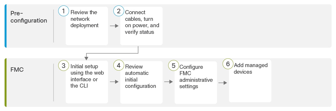
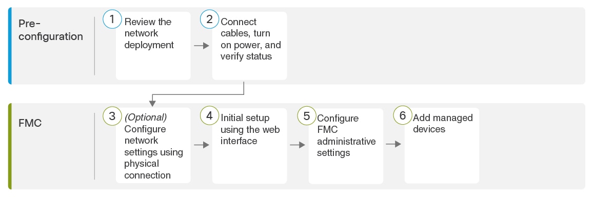
End to End Procedure to Install the FMC for Versions 6.5 and Later
See the following tasks to deploy and configure a FMC that will run Versions 6.5 and later.
|
|
Pre-Configuration |
|
|
|
Pre-Configuration |
Connect Cables Turn On Power Verify Status for Versions 6.5 and Later |
|
|
FMC |
Use one of the following: |
|
|
FMC |
Review Automatic Initial Configuration for Versions 6.5 and Later |
|
|
FMC |
|
|
|
FMC |
Connect Cables Turn On Power Verify Status for Versions 6.5 and Later
This procedure references the rear panel ports of the FMC 2500 and 4500. The FMC 1000 is the same except that it does not have the two 10-G SFP+ ports above the Ethernet ports.
AC power supplies have internal grounding so no additional chassis grounding is required when the supported AC power cords are used. For more information about supported power cords, see the Cisco Firepower Management Center 1000, 2500, and 4500 Hardware Installation Guide.
After rack-mounting the chassis, follow these steps to connect cables, turn on power, and verify connectivity. Use the following figure to identify the rear panel ports.
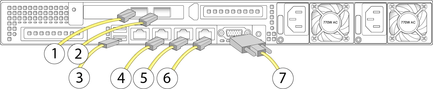
|
1 |
(Models 2500 and 4500 only.) eth2 management interface 10-Gigabit Ethernet SFP+ support Use only Cisco-supported SFPs. |
2 |
(Models 2500 and 4500 only.) eth3 management interface 10-Gigabit Ethernet SFP+ support Use only Cisco-supported SFPs. |
|
3 |
USB keyboard port |
4 |
Serial console port Use the console cable (RJ45 to DB9) to connect a computer to the appliance. |
|
5 |
eth0 management interface (labeled "1") Gigabit Ethernet 10/100/1000 Mbps interface, RJ-45 eth0 is the default management interface. |
6 |
eth1 management interface (labeled "2") Gigabit Ethernet 10/100/1000 Mbps interface, RJ-45 |
|
7 |
VGA port (DE-15 connector) Console messages are sent to this port by default. |
Before you begin
Important |
-
Rack-mount the appliance as described in the Cisco Firepower Management Center 1000, 2500, and 4500 Hardware Installation Guide.
SUMMARY STEPS
- (Optional, applies only to models 2500 and 4500) eth2 management interface —If your model includes 10-Gigabit Ethernet SFP+ interfaces, install any FMC-supported SFP+ transceivers and cables as needed. You can connect this interface to the same or different network from your other management interfaces depending on your network needs. For more information about management interfaces and network topology, see the Firepower Management Center Configuration Guide.
- (Optional, applies only to models 2500 and 4500) eth3 management interface —If your model includes 10-Gigabit Ethernet SFP+ interfaces, install any FMC-supported SFP+ transceivers and cables as needed. You can connect this interface to the same or different network from your other management interfaces depending on your network needs. For more information about management interfaces and network topology, see the Firepower Management Center Configuration Guide.
- (Optional) USB port —Connect a keyboard to the USB port.
- (Optional) Use the RJ-45 to DP-9 console cable supplied with the appliance (Cisco part number 72-3383-XX) to connect a local computer to the FMC serial port. You can use this connection for serial or Lights Out Management access to the FMC; see Set Up Alternate FMC Access.
- eth0 management interface (labeled "1" on the rear panel)— Using an Ethernet cable, connect the eth0 interface to the default management network reachable from your management PC. This interface is the default management interface and is enabled by default. Confirm that the link LED is on for both the network interface on the local computer and the FMC management interface.
- (Optional) eth1 management interface (labeled "2" on the rear panel)—Connect this management interface to the same or different network from your other management interfaces depending on your network needs. For information about management interfaces and network topology, see the Firepower Management Center Configuration Guide for your version.
- (Optional) VGA port —Connect a monitor to the VGA port.
- Power supply—Use one of the supported power cords to connect the power supplies of the chassis to your power source. For more information about supported power cords, see the Cisco Firepower Management Center 1000, 2500, and 4500 Hardware Installation Guide.
- Power—Press the Power button on the front of the chassis, and verify that the front panel power status LED is on.
- Verify— Use the diagram in Front Panel LEDs and their States to check that the front-panel LEDs reflect a good status.
DETAILED STEPS
|
Step 1 |
(Optional, applies only to models 2500 and 4500) eth2 management interface —If your model includes 10-Gigabit Ethernet SFP+ interfaces, install any FMC-supported SFP+ transceivers and cables as needed. You can connect this interface to the same or different network from your other management interfaces depending on your network needs. For more information about management interfaces and network topology, see the Firepower Management Center Configuration Guide. Each FMC-supported SFP+ transceiver (FS2K-NIC-SFP/FS4K-NIC-SFP) has an internal serial EEPROM that is encoded with security information. This encoding allows us to identify and validate that the SFP transceiver meets the requirements for the FMC chassis.
|
||
|
Step 2 |
(Optional, applies only to models 2500 and 4500) eth3 management interface —If your model includes 10-Gigabit Ethernet SFP+ interfaces, install any FMC-supported SFP+ transceivers and cables as needed. You can connect this interface to the same or different network from your other management interfaces depending on your network needs. For more information about management interfaces and network topology, see the Firepower Management Center Configuration Guide. Each FMC-supported SFP+ transceiver (FS2K-NIC-SFP/FS4K-NIC-SFP) has an internal serial EEPROM that is encoded with security information. This encoding allows us to identify and validate that the SFP transceiver meets the requirements for the FMC chassis.
|
||
|
Step 3 |
(Optional) USB port —Connect a keyboard to the USB port. You can use this connection and a monitor connected to the VGA port to
configure network settings and perform initial setup at the CLI.
|
||
|
Step 4 |
(Optional) Use the RJ-45 to DP-9 console cable supplied with the appliance (Cisco part number 72-3383-XX) to connect a local computer to the FMC serial port. You can use this connection for serial or Lights Out Management access to the FMC; see Set Up Alternate FMC Access. |
||
|
Step 5 |
eth0 management interface (labeled "1" on the rear panel)— Using an Ethernet cable, connect the eth0 interface to the default management network reachable from your management PC. This interface is the default management interface and is enabled by default. Confirm that the link LED is on for both the network interface on the local computer and the FMC management interface. You can use this connection to configure network settings and perform initial setup using HTTPS. You can also use this connection to perform routine management, and to manage devices from the FMC web interface. |
||
|
Step 6 |
(Optional) eth1 management interface (labeled "2" on the rear panel)—Connect this management interface to the same or different network from your other management interfaces depending on your network needs. For information about management interfaces and network topology, see the Firepower Management Center Configuration Guide for your version. |
||
|
Step 7 |
(Optional) VGA port —Connect a monitor to the VGA port. You can use this connection and a keyboard connected to a USB port to
configure network settings and perform initial setup at the CLI.
|
||
|
Step 8 |
Power supply—Use one of the supported power cords to connect the power supplies of the chassis to your power source. For more information about supported power cords, see the Cisco Firepower Management Center 1000, 2500, and 4500 Hardware Installation Guide. |
||
|
Step 9 |
Power—Press the Power button on the front of the chassis, and verify that the front panel power status LED is on. |
||
|
Step 10 |
Verify— Use the diagram in Front Panel LEDs and their States to check that the front-panel LEDs reflect a good status. |
Perform Initial Setup at the Web Interface for Versions 6.5 and Later
If you have HTTPS access to the FMC IP address (either the address obtained from DHCP or the default 192.168.45.45), you can perform initial setup using HTTPS at the appliance web interface. If you need to manually set the FMC IP address, see FMC Initial Setup Using the CLI for Versions 6.5 and Later.
When you log into the FMC web interface for the first time, the FMC presents an Initial Configuration Wizard to enable you to quickly and easily configure basic settings for the appliance. This wizard consists of three screens and one pop-up dialog box:
-
The first screen forces you to change the password for the admin user from the default value of Admin123.
-
The second screen presents the End User License Agreement (EULA), which you are required to accept before using the appliance.
-
The third screen allows you to change network settings for the appliance management interface. This page is prepopulated with current settings, which you may change.
If you are setting up an appliance after restoring it to factory defaults (see About the Restore Process) and you did not delete the appliance's license and network settings, the prompts will be pre-populated with the retained values.
-
The wizard performs validation on the values you enter on this screen to confirm the following:
-
Syntactical correctness
-
Compatibility of the entered values (for instance, compatible IP address and gateway, or DNS provided when NTP servers are specified using FQDNs)
-
Network connectivity between the FMC and the DNS and NTP servers
The wizard displays the results of these tests in real time on the screen, which allows you to make corrections and test the viability of your configuration before clicking Finish at the bottom of the screen. The NTP and DNS connectivity tests are nonblocking; you can click Finish before the wizard completes the connectivity tests. If the system reports a connectivity problem after you click Finish, you cannot change the settings in the wizard, but you can configure these connections using the web interface after completing the initial setup.
The system does not perform connectivity testing if you enter configuration values that would result in cutting off the existing connection between the FMC and the browser. In this case the wizard displays no connectivity status information for DNS or NTP.
-
-
After you have completed the three wizard screens, a pop-up dialog box appears that offers you the opportunity to (optionally) quickly and easily set up Smart Licensing.
When you have completed the Initial Configuration Wizard and completed or dismissed the Smart Licensing dialog, the system displays the device management page, described in “Device Management” in the Firepower Management Center Device Configuration Guide for your version.
Before you begin
-
Install the FMC as described in Connect Cables Turn On Power Verify Status for Versions 6.5 and Later.
-
Be sure you have the following information needed for the FMC to communicate on your management network:
-
An IPv4 management IP address.
The FMC interface is preconfigured to accept an IP4 address assigned by DHCP. Consult with your system administrator to determine what IP address your DHCP has been configured to assign to the FMC MAC address. In scenarios where no DHCP is available, the FMC interface uses the IPv4 address 192.168.45.45.
-
A network mask and a default gateway (if not using DHCP).
-
-
If you are not using DHCP, configure a local computer with the following network settings:
-
IP address: 192.168.45.2
-
Netmask: 255.255.255.0
-
Default gateway: 192.168.45.1
Disable any other network connections on this computer.
-
Procedure
|
Step 1 |
Use a web browser to navigate to the FMC's IP address: https://<Firepower Management Center-IP>. The login page appears. |
||
|
Step 2 |
Log into the FMC using admin as the username and Admin123 as the password for the admin account. (The password is case-sensitive.) |
||
|
Step 3 |
At the Change Password screen: |
||
|
Step 4 |
At the User Agreement screen, read the EULA and click Accept to proceed. If you click Decline the wizard logs you out of the FMC. |
||
|
Step 5 |
Click Next. |
||
|
Step 6 |
At the Change Network Settings screen:
|
||
|
Step 7 |
Click Finish. The wizard performs validation on the values you enter on this screen to confirm syntactical correctness, compatibility of the entered values, and network connectivity between the FMC and the DNS and NTP servers. If the system reports a connectivity problem after you click Finish, you cannot change the settings in the wizard, but you can configure these connections using the FMC web interface after completing the initial setup. |
What to do next
-
If you changed network settings during initial configuration, you need to reconnect to the FMC using the new network information.
-
The system displays a pop-up dialog box that offers you the opportunity to quickly and easily set up Smart Licensing. Using this dialog box is optional; if your FMC will be managing Firepower Threat Defenses and you are familiar with Smart Licensing, use this dialog. Otherwise dismiss this dialog and refer to ”Licensing” in the Firepower Management Center Administration Guide for your version.
-
Review the weekly maintenance activites the FMC configures automatically as a part of the initial configuration process. These activities are designed to keep your system up-to-date and your data backed up. See Review Automatic Initial Configuration for Versions 6.5 and Later .
-
When you have completed the Initial Configuration Wizard and completed or dismissed the Smart Licensing dialog, the system displays the device management page, described in the Cisco Firepower Management Center Device Configuration Guide. Establish basic configuration for your FMC as described in Configure FMC Administrative Settings.
-
You can optionally configure the FMC for Serial over LAN or Lights-Out-Management access as described in Set Up Alternate FMC Access.
FMC Initial Setup Using the CLI for Versions 6.5 and Later
You can perform initial setup using the CLI as an alternative to using the web interface. You must complete an Initial Configuration Wizard that configures the new appliance to communicate on your trusted management network. The wizard requires that you accept the end user license agreement (EULA) and change the administrator password.
Before you begin
-
Install the FMC as described in Connect Cables Turn On Power Verify Status for Versions 6.5 and Later.
-
Be sure you have the following information needed for the FMCv to communicate on your management network:
-
An IPv4 management IP address.
The FMC interface is preconfigured to accept an IP4 address assigned by DHCP. Consult with your system administrator to determine what IP address your DHCP has been configured to assign to the FMC MAC address. In scenarios where no DHCP is available, the FMC interface uses the IPv4 address 192.168.45.45.
-
A network mask and a default gateway (if not using DHCP).
-
-
Connect to the FMC using one of three methods:
-
Establish an SSH connection using the IPv4 management IP address.
-
Connect a USB keyboard and VGA monitor to the FMC for console access.
-
Connect a local computer to the FMC serial port with an RJ-45 to DP-9 console cable.
-
Procedure
|
Step 1 |
Log into the FMCv at the console using admin as the username and Admin123 as the password for the admin account. Note that the password is case-sensitive. |
||||
|
Step 2 |
When prompted, press Enter to display the End User License Agreement (EULA). |
||||
|
Step 3 |
Review the EULA. When prompted, enter yes, YES, or press Enter to accept the EULA.
|
||||
|
Step 4 |
To ensure system security and privacy, the first time you log in to the FMC you are required to change the admin password. When the system prompts for a new password, enter a new password complying with the restrictions displayed, and enter the same password again when the system prompts for confirmation.
|
||||
|
Step 5 |
Answer the prompts to configure network settings. When following the prompts, for multiple-choice questions, your options are listed in parentheses, such as (y/n). Defaults are listed in square brackets, such as [y]. Note the following when responding to prompts:
Example: |
||||
|
Step 6 |
The system displays a summary of your configuration selections. Review the settings you have entered. Example: |
||||
|
Step 7 |
The final prompt gives you the opportunity to confirm the settings.
Example: |
||||
|
Step 8 |
After you have accepted the settings, you can enter exit to exit the FMC CLI. |
What to do next
-
You can connect to the FMC web interface using the network information you have just configured.
-
Review the weekly maintenance activites the FMC configures automatically as a part of the initial configuration process. These activities are designed to keep your system up-to-date and your data backed up. See Review Automatic Initial Configuration for Versions 6.5 and Later .
-
You can optionally configure the FMC for Serial over LAN or Lights-Out-Management access as described in Set Up Alternate FMC Access.
Review Automatic Initial Configuration for Versions 6.5 and Later
As a part of initial configuration (whether performed through the Initial Configuration Wizard or through the CLI), the FMC automatically configures maintenance tasks to keep your system up-to-date and your data backed up.
These tasks are scheduled in UTC, which means that when they occur locally depends on the date and your specific location. Also, because tasks are scheduled in UTC, they do not adjust for daylight saving time, summer time, or any such seasonal adjustments that you may observe in your location. If you are affected, scheduled tasks occur one hour "later" in the summer than in the winter, according to local time.
Note |
We strongly recommend you review the auto scheduled configurations, confirm that the FMC has established them successfully, and adjust them if necessary. |
-
Weekly GeoDB Updates
The FMC automatically schedules GeoDB updates to occur each week at the same randomly selected time. You can observe the status of this update using the web interface Message Center. You can see the configuration for this automatic update in the web interface under >Recurring Geolocation Updates. If the system fails to configure the update and your FMC has internet access, we recommend you configure regular GeoDB updates as described in the Firepower Management Center Administration Guide for your version.
-
Weekly FMC Software Updates
The FMC automatically schedules a weekly task to download the latest software for the FMC and its managed devices. This task is scheduled to occur between 2 and 3 AM UTC on Sunday mornings; depending on the date and your specific location this can occur any time from Saturday afternoon to Sunday afternoon local time. You can observe the status of this task using the web interface Message Center. You can see the configuration for this task in the web interface under . If the task scheduling fails and your FMC has internet access, we recommend you schedule a recurring task for downloading software updates as described in the Firepower Management Center Administration Guide for your version.
This task only downloads software patch and hotfix updates for the version your appliances are currently running; it it your responsibility to install any updates this task downloads. See the Cisco FMC Upgrade Guide for more information.
-
Weekly FMC Configuration Backup
The FMC automatically schedules a weekly task to perform a locally-stored configuration-only backup at 2 AM UTC on Monday mornings; depending on the date and your specific location this can occur any time from Saturday afternoon to Sunday afternoon local time. You can observe the status of this task using the web interface Message Center. You can see the configuration for this task in the web interface under . If the task scheduling fails, we recommend you schedule a recurring task to perform backups as described in the Firepower Management Center Administration Guide for your version.
-
Vulnerability Database Update
In Versions 6.6+, the FMC downloads and installs the latest vulnerability database (VDB) update from the Cisco support site. This is a one-time operation. You can observe the status of this update using the web interface Message Center. To keep your system up to date, if your FMC has internet access, we recommend you schedule tasks to perform automatic recurring VDB update downloads and installations as described in the Firepower Management Center Administration Guide for your version.
-
Daily Intrusion Rule Update
In Versions 6.6+, the FMC configures a daily automatic intrusion rule update from the Cisco support site. The FMC deploys automatic intrusion rule upates to affected managed devices when it next deploys affected policies. You can observe the status of this task using the web interface Message Center. You can see the configuration for this task in the web interface under . If configuring the update fails and your FMC has internet access, we recommend you configure regular intrusion rule updates as described in the Firepower Management Center Administration Guide for your version.
Install the FMC for Software Versions 6.2 - 6.4
Follow these instructions to install the FMC that will run Versions 6.2 - 6.4.
Review Network Deployment for Versions 6.2-6.4
To deploy the FMC you need information about the environment within which it will operate. The following figure shows an example network configuration for a firewall deployment.
By default the FMC connects to your local management network through its management interface (eth0). Through this connection the FMC communicates with a management computer; managed devices; services such as DHCP, DNS, NTP; and the internet.
The FMC requires internet access to support Smart Licensing, threat intelligence director, and malware defense services. Depending on services provided by your local management network, the FMC may also require internet access to reach an NTP or DNS server. You can configure your network to provide internet access to the FMC directly or through a firewall device.
You can upload updates for system software, as well as the Vulnerability Database (VDB), Geolocation Database (GEoDB), and intrusion rules directly to the FMC from an internet connection or from a local computer that has previously downloaded these updates from the internet.
To establish the connection between the FMC and one of its managed devices, you need the IP address of at least one of the devices: the FMC or the managed device. We recommend using both IP addresses if available. However, you may only know one IP address. For example, managed devices may be using private addresses behind NAT, so you only know the FMC address. In this case you can specify the FMC address on the managed device plus a one-time, unique password of your choice called a NAT ID. On the FMC, you specify the same NAT ID to identify the managed device.
The initial setup and configuration process described in this document assumes the FMC will have internet access. If you are deploying the FMC in an air-gapped environment, see the Firepower Management Center Administration Guide for your version for alternative methods you can use to support certain features such as configuring a proxy for HTTP communications, or using a Smart Software Satellite Server for Smart Licensing. In a deployment where the FMC has internet access, you can upload updates for system software, as well as the Vulnerability Database (VDB), Geolocation Database (GEoDB), and intrusion rules directly to the FMC from an internet connection. But if the FMC does not have internet access, the FMC can upload these updates from a local computer that has previously downloaded them from the internet. Additionally, in an air-gapped deployment you might use the FMC to serve time to devices in your deployment.
Initial Network Configuration for FMCs Using Versions 6.2- 6.4 :
-
Management Interface
The FMC interface (eth0) uses the default IPv4 address 192.168.45.45, netmask 255.255.255.0, and gateway 192.168.45.1. During initial setup you can accept these defaults or specify different values.
If you choose to use IPv6 addressing for the management interface, you have the option of using router autoconfiguration, or you must provide the IPv6 address, prefix length, and gateway. If your network uses DNS, during initial configuration you can provide a hostname to identify the FMC.
-
DNS Server(s)
If your network uses DNS you can specify the IP addresses for up to three DNS servers during initial configuration. If you are using an evaluation license you may choose not to use DNS. (During initial configuration you can also provide a hostname and domain to faciliate communications between the FMC and other hosts through DNS; you can configure additional domains after completing intial setup.)
-
NTP Server(s)
Synchronizing the system time on your FMC and its managed devices is essential to successful operation of your System. Configuring time synchronization is not required on initial setup, but we recommend that you configure your FMC to use trusted NTP servers. During initial setup you will need the host names or IP addresses of those NTP servers.
End to End Procedure to Install the FMC to Run Software Versions 6.2 - 6.4
See the following tasks to deploy and configure the FMC that will run Versions 6.2- 6.4.
Connect Cables, Turn On Power, Verify Status for Versions 6.2 - 6.4
This procedure references the rear panel ports of the FMC 2500 and 4500. The FMC 1000 is the same except that it does not have the two 10-G SFP+ ports above the Ethernet ports.
AC power supplies have internal grounding so no additional chassis grounding is required when the supported AC power cords are used. For more information about supported power cords, see the Cisco Firepower Management Center 1000, 2500, and 4500 Hardware Installation Guide.
After rack-mounting the chassis, follow these steps to connect cables, turn on power, and verify connectivity. Use the following figure to identify the rear panel ports.
|
1 |
(Models 2500 and 4500 only.) eth2 management interface 10-Gigabit Ethernet SFP+ support Use only Cisco-supported SFPs. |
2 |
(Models 2500 and 4500 only.) eth3 management interface 10-Gigabit Ethernet SFP+ support Use only Cisco-supported SFPs. |
|
3 |
USB keyboard port |
4 |
Serial console port Use the console cable (RJ45 to DB9) to connect a computer to the appliance. |
|
5 |
eth0 management interface (labeled "1") Gigabit Ethernet 10/100/1000 Mbps interface, RJ-45 eth0 is the default management interface. |
6 |
eth1 management interface (labeled "2") Gigabit Ethernet 10/100/1000 Mbps interface, RJ-45 |
|
7 |
VGA port (DE-15 connector) Console message are sent to this port by default. |
Before you begin
Important |
-
Rack-mount the appliance as described in the Cisco Firepower Management Center 1000, 2500, and 4500 Hardware Installation Guide.
Procedure
|
Step 1 |
(Optional, applies only to models 2500 and 4500) eth2 management interface —If your model includes 10-Gigabit Ethernet SFP+ interfaces, install any FMC-supported SFP+ transceivers and cables as needed. You can connect this interface to the same or different network from your other management interfaces depending on your network needs. For more information about management interfaces and network topology, see the Firepower Management Center Configuration Guide. Each FMC-supported SFP+ transceiver (FS2K-NIC-SFP/FS4K-NIC-SFP) has an internal serial EEPROM that is encoded with security information. This encoding allows us to identify and validate that the SFP transceiver meets the requirements for the FMC chassis.
|
||
|
Step 2 |
(Optional, applies only to models 2500 and 4500) eth3 management interface —If your model includes 10-Gigabit Ethernet SFP+ interfaces, install any FMC-supported SFP+ transceivers and cables as needed. You can connect this interface to the same or different network from your other management interfaces depending on your network needs. For more information about management interfaces and network topology, see the Firepower Management Center Configuration Guide. Each FMC-supported SFP+ transceiver (FS2K-NIC-SFP/FS4K-NIC-SFP) has an internal serial EEPROM that is encoded with security information. This encoding allows us to identify and validate that the SFP transceiver meets the requirements for the FMC chassis.
|
||
|
Step 3 |
(Optional) USB port —Connect a keyboard to the USB port. You can use this connection and a monitor connected to the VGA port to
configure network settings for the FMC before performing initial setup using the web interface.
|
||
|
Step 4 |
(Optional) Use the RJ-45 to DP-9 console cable supplied with the appliance (Cisco part number 72-3383-XX) to connect a local computer to the FMC serial port. You can use this connection for serial or Lights Out Management access to the FMC; see Set Up Alternate FMC Access. |
||
|
Step 5 |
eth0 management interface (labeled "1" on the rear panel)— Using an Ethernet cable, connect the eth0 interface to the default management network reachable from your management PC. This interface is the default management interface and is enabled by default. Confirm that the link LED is on for both the network interface on the local computer and the FMC management interface. You can use this connection to configure network settings and perform initial setup using HTTPS. You can also use this connection to perform routine management, and to manage devices from the FMC web interface. |
||
|
Step 6 |
(Optional) eth1 management interface (labeled "2" on the rear panel)—Connect this management interface to the same or different network from your other management interfaces depending on your network needs. For information about management interfaces and network topology, see the Firepower Management Center Configuration Guide for your version. |
||
|
Step 7 |
(Optional) VGA port —Connect a monitor to the VGA port. You can use this connection and a keyboard connected to a USB port to
configure network settings for the FMC before performing initial setup using the web interface.
|
||
|
Step 8 |
Power supply—Use one of the supported power cords to connect the power supplies of the chassis to your power source. For more information about supported power cords, see the Cisco Firepower Management Center 1000, 2500, and 4500 Hardware Installation Guide. |
||
|
Step 9 |
Power—Press the Power button on the front of the chassis, and verify that the front panel power status LED is on. |
||
|
Step 10 |
Verify— Use the diagram in Front Panel LEDs and their States to check that the front-panel LEDs reflect a good status. |
(Optional) Configure Network Settings Using a Physical Connection for Software Versions 6.2 - 6.4
You can use a USB keyboard and VGA monitor connected directly to the appliance to access the Linux shell and run a script to establish the network configuration for the appliance. When performing this task, refer to the diagram of Physical Interfaces to identify the rear-panel ports.
Procedure
|
Step 1 |
If you have not already, connect the monitor to the VGA port and the keyboard to one of the USB ports on the rear of the chassis. |
|
Step 2 |
Access the Linux shell on the FMC using admin as the username and Admin123 as the password. (The password is case-sensitive.) Use the steps appropriate to your version; see Access the CLI or the Linux Shell on the FMC. |
|
Step 3 |
Run the following script to configure the FMC network settings: sudo /usr/local/sf/bin/configure-network. |
|
Step 4 |
Answer the prompts to provide the IPv4 and (optionally ) IPv6 configuration information for your appliance. |
|
Step 5 |
The final prompt gives you the opportunity to confirm the settings. Are these settings correct? (y or n)Review the settings you have entered:
|
|
Step 6 |
After you have accepted the settings, enter exit to log out of the shell. |
What to do next
Complete the setup process as described in FMC Initial Setup Using the Web Interface for Software Versions 6.2 - 6.4.
FMC Initial Setup Using the Web Interface for Software Versions 6.2 - 6.4
For all the FMCs, you must complete the setup process by logging into the FMC web interface and choosing initial configuration options on a setup page. At a minimum, you must change the administrator password, specify network settings if you haven't already, and accept the EULA.
Procedure
|
Step 1 |
Direct your browser to https://mgmt_ip/, where mgmt_ip is the IP address of the FMC interface:
|
||
|
Step 2 |
Log in using admin as the username and Admin123 as the password. (The password is case-sensitive.) |
||
|
Step 3 |
In the Change Password section of the Setup page, change the password for the admin accounts. The admin account for the web interface has Administrator privileges and cannot be deleted. We recommend that you use a strong password that is at least eight alphanumeric characters of mixed case and includes at least one numeric character. Avoid using words that appear in a dictionary.
|
||
|
Step 4 |
The FMC’s network settings allow it to communicate on your management network. Configure these settings in the Network Settings section of the Setup page:
|
||
|
Step 5 |
(Optional) In the Time Settings section of the Setup page you can set the time for a FMC one of two ways: either manually or using the network time protocol (NTP) from an NTP server.
To choose the time zone used on the local web interface for the admin account, click the current time zone value and choose a time zone from the pop-up window.
|
||
|
Step 6 |
(Optional) If you plan to perform intrusion detection and prevention in your deployment, in the Recurring Rule Update Imports section of the Setup page, we recommend that you check Enable Recurring Rule Update Imports from the Support Site. You can specify the Import Frequency, as well as configure the system to perform an intrusion Policy Deploy after each rule update. To perform a rule update as part of the initial configuration process, check the Install Now checkbox. The Cisco Talos Intelligence Group releases intrusion rule updates as new vulnerabilities become known. Rule updates provide new and updated intrusion rules and preprocessor rules, modified states for existing rules, and modified default intrusion policy settings. Rule updates may also delete rules and provide new rule categories and system variables. Rule updates may contain new binaries. Make sure your process for downloading and installing rule updates complies with your security policies. In addition, rule updates may be large, so make sure to import rules during periods of low network use. |
||
|
Step 7 |
(Optional) If you plan to perform geolocation-related analysis in your deployment, in the Recurring Geolocation Updates section of the Setup page, we recommend that you check Enable Recurring Weekly Updates from the Support Site and specify the Update Start Time using the provided fields. To perform a GeoDB update as part of the initial configuration process, check the Install Now checkbox. GeoDB updates may be large and may take up to 45 minutes to install after download. You should update the GeoDB during periods of low network use. FMCs can display geographical information about the routed IP addresses associated with events generated by the system, as well as monitor geolocation statistics in the dashboard and Context Explorer. The FMC’s geolocation database (GeoDB) contains information to support this feature such as an IP address’s associated ISP, connection type, proxy information, and exact location. Enabling regular GeoDB updates ensures that the system uses up-to-date geolocation information. |
||
|
Step 8 |
(Optional) In the Automatic Backups section of the Setup page, you can check Enable Automatic Backups to create a scheduled task that creates a weekly backup of the configurations on the FMC that can be restored in case of failure. |
||
|
Step 9 |
You use the FMC to manage licenses for the devices it manages. The FMC can manage devices regardless of the type of license they require:
The Firepower Management Center Administration Guide provides more information about Classic Licenses and Smart Licenses, the types of licenses for each class, and how to manage the licenses across your deployment. |
||
|
Step 10 |
Read the End User License Agreement carefully; if you agree to abide by its provisions, then check the I have read and agree to the End User License Agreement checkbox. |
||
|
Step 11 |
Make sure that all the information you provided is correct, and click Apply. The FMC applies your configuration according to your selections, logs you into the web interface as the admin user (which has the Administrator role), and displays the Summary Dashboard page.
|
||
|
Step 12 |
If you connected directly to the appliance's management interface using an Ethernet cable, once you click Apply you will be disconnected from the FMC because its IP address has changed. Disconnect the computer and connect the FMC interface to the management network. To complete the remaining procedures in the guide use a browser on a computer on the management network to access the FMC GUI at the IP address or host name that you just configured. |
||
|
Step 13 |
Verify that the initial setup was successful by monitoring the Tasks tab in the Message Center. |
What to do next
-
Perform the activities described in Configure FMC Administrative Settings.
-
Optionally, configure the FMC for Serial or Lights-Out Management (LOM) access; see Set Up Alternate FMC Access.
(Optional) Add Classic Licenses During Initial Setup (Versions 6.2 - 6.4)
You use the FMC to manage classic licenses for 7000 and 8000 Series, ASA with FirePOWER Services, and NGIPSv.
Note |
You must enable Classic Licenses on your managed devices before you can use licensed features. You can enable a license during the initial setup of the FMC (as described in the procedure below), when you add a device to the FMC, or by editing the device’s general properties after you add the device. |
Before you begin
Before you add a classic license to the FMC, make sure you have the Product Authorization Key (PAK) provided by Cisco when you purchased the license. If you have a legacy, pre-Cisco license, contact Cisco TAC.
Procedure
|
Step 1 |
Obtain the License Key for your chassis from the License Settings section on the Initial Setup page. The License Key is clearly labeled (for example, 66:18:E7:6E:D9:93:35). |
||
|
Step 2 |
To obtain your license, navigate to https://www.cisco.com/go/license/ where you are prompted for the License Key (for example, 66:18:E7:6E:D9:93:35) and the PAK.
|
||
|
Step 3 |
Follow the on-screen instructions to generate a license or licenses, which will be emailed to you. |
||
|
Step 4 |
Paste the license or licenses in the validation box and click Add/Verify. |
Configure FMC Administrative Settings
After you complete the initial setup process for the FMC and verify its success, we recommend that you complete various administrative tasks that make your deployment easier to manage. You should also complete any tasks you skipped during the initial setup, such as licensing. Establish these configurations using the default admin account or another account with Administrator access.
For detailed information on any the tasks described in the following sections, as well as information on how you can begin to configure your deployment, see the Firepower Management Center Administration Guide for your software version.
Log In to the FMC Web Interface as an Administrator
If you have not already logged into the FMC web interface to perform initial setup, you need to do so to configure the FMC administrative settings. Use the default admin account, or if you have already created additional user accounts, use an account with Administrator access.
Users are restricted to a single active session. If you try to log in with a user account that already has an active session, the system prompts you to terminate the other session or log in as a different user.
In a NAT environment where multiple FMCs share the same IP address and are differentiated by port numbers:
-
Each FMC can support only one login session at a time.
-
To access different FMCs, use a different browser for each login (for example Firefox and Chrome), or set the browser to incognito or private mode.
Procedure
|
Step 1 |
Direct your browser to https://ipaddress_or_hostname/, where ipaddress or hostname corresponds to your FMC. |
|
Step 2 |
In the Username and Password fields, enter your user name and password. |
|
Step 3 |
Click Login. |
Create Individual User Accounts
After you complete the initial setup, the only web interface user on the system is the admin user, which has the Administrator role and access. Users with that role have full menu and configuration access to the system. We recommend that you limit the use of the admin account (and the Administrator role) for security and auditing reasons.
Note |
The admin accounts for accessing the FMC using the shell and accessing the FMC using the web interface are not the same, and may use different passwords. |
The system includes ten predefined user roles designed for a variety of administrators and analysts using the web interface. Creating a separate account for each person who uses the system allows your organization not only to audit actions and changes made by each user, but also to limit each person’s associated user access role or roles. This is especially important on the FMC, where you perform most of your configuration and analysis tasks. For example, an analyst needs access to event data to analyze the security of your network, but may not require access to administrative functions for the deployment. See the Firepower Management Center Administration Guide for your version for user role descriptions.
For information on externally-authenticated user accounts or user accounts in multi-domain deployments see the Firepower Management Center Administration Guide for your version .
Procedure
|
Step 1 |
Choose . |
|
Step 2 |
On the Users tab, click Create User. |
|
Step 3 |
Enter a User Name and provide or choose values for the characteristics of the user account. |
|
Step 4 |
Click Save. |
Configure Time Settings
Synchronizing the system time on your FMC and its managed devices is essential to successful operation of your System. We recommend that you specify NTP servers within your network during FMC initial configuration, but should that fail, you can add an NTP server after initial configuration is complete.
If your FMC is unable to reach an NTP server, see the Firepower Management Center Administration Guide for your version for alternative ways to configure time for your firewall deployment.
Procedure
|
Step 1 |
Choose . |
|
Step 2 |
Disable the Serve Time via NTP option. |
|
Step 3 |
Choose Via NTP for the Set My Clock option. |
|
Step 4 |
For Versions 6.2 - 6.4:Click Add and enter the host name or IP address for an NTP server accessible from your FMC. Then click Save. For Versions 6.5+: Click Add and enter the host name or IP address for an NTP server accessible from your FMC. Then click Add, then Save. |
Configure Smart Licensing
The FMC itself does not require licenses, but if you plan to manage Firepower Threat Defense devices, you need to create a Smart Account if you do not already have one, and purchase the Smart Licenses you need to support threat and malware detection and URL filtering features. Visit https://software.cisco.com/smartaccounts/setup#accountcreation-account. For information, see https://www.cisco.com/c/en/us/buy/smart-accounts.html.
FTD devices come with a base license that allow you to:
-
configure the Firepower Threat Defense devices to perform switching and routing (including DHCP relay and NAT).
-
configure the Firepower Threat Defense devices as a high availability pair.
-
configure security modules as a cluster within a Firepower 9300 chassis (intra-chassis clustering)
-
configure Firepower 9300 or Firepower 4100 series devices running Firepower Threat Defense as a cluster (inter-chassis clustering)
-
implement user and application control by adding user and application conditions to access control rules
Threat and malware detection and URL filtering features require additional, optional licenses. As you plan your deployment, determine how many Firepower Threat Defense devices the FMC will manage and what features you need to license for each.
Note |
This document provides a streamlined version of the instructions for configuring Smart Licensing, useful for customers already familiar with the process. If you are new to Smart Licensing, or if you need to configure Smart Licensing for an air-gapped deployment, devices using high availability, clustered devices, multitenancy, or export-controlled functionality, see the Firepower Management Center Administration Guide for your version. |
For Versions 6.5+: If you already have a Smart Account, have purchased licenses and are familiar with Smart Licensing you can use the dialog box the system displays after you have completed the Initial Configuration Wizard. Alternatively, after completing the wizard you can use the same license configuration process as for Versions 6.2 - 6.4.
For Versions 6.2 - 6.4: Add Smart licenses after completing initial setup. For each license:
-
Obtain a product license registration token for Smart Licensing from the Cisco Smart Software Manager (CSSM). Consult the Getting Started Guide for your device to determine the license PIDs available for that device.
-
Use the token to register the FMC to CSSM.
-
When you add a managed Firepower Threat Defense to the FMC, assign the license to the device.
Obtain a Product License Registration Token for Smart Licensing
Before you begin
-
Create a Smart Account and purchase the number and types of licenses that you require. Visit https://software.cisco.com/smartaccounts/setup#accountcreation-account. For information, see https://www.cisco.com/c/en/us/buy/smart-accounts.html.
-
Verify the licenses appear in your Smart Account.
-
Make sure you have the credentials to sign in to the Cisco Smart Software Manager.
Procedure
|
Step 1 |
Go to https://software.cisco.com. |
|
Step 2 |
Click Smart Software Licensing (in the License section.) |
|
Step 3 |
Sign in to the Cisco Smart Software Manager. |
|
Step 4 |
Click Inventory. |
|
Step 5 |
Click General. |
|
Step 6 |
Click New Token. |
|
Step 7 |
For Description, enter a name that uniquely and clearly identifies the FMC for which you will use this token. |
|
Step 8 |
Enter an expiration time within 365 days. This determines how much time you have to register the token to a FMC. |
|
Step 9 |
Click Create Token. |
|
Step 10 |
Locate your new token in the list and click Actions, then choose Copy or Download. |
|
Step 11 |
Save your token in a safe place until you are ready to enter it into your FMC. |
What to do next
Continue with Register Smart Licenses.
Register Smart Licenses
Before you begin
-
Ensure that the FMC can reach the Cisco Smart Software Manager (CSSM) server at tools.cisco.com:443.
-
Make sure the FMC has established a connection with an NTP server. During registration, a key exchange occurs between the NTP server and the Cisco Smart Software Manager, so time must be in sync for proper registration.
If you are deploying the Firepower Threat Defense on a Firepower 4100/9300 chassis, you must configure NTP on the firewall chassis using the same NTP server for the chassis as for the FMC.
-
Generate the necessary product license registration token from CSSM. See Obtain a Product License Registration Token for Smart Licensing, including all prerequisites. Make sure the token is accessible from the machine from which you will access your FMC.
Procedure
|
Step 1 |
Choose > Register. |
||
|
Step 2 |
Paste the token you generated from CSSM into the Product Instance Registration Token field. Make sure there are no empty spaces or blank lines at the beginning or end of the text. |
||
|
Step 3 |
For Version 6.2.3 +: Decide whether to send usage data to Cisco.
|
||
|
Step 4 |
Click Apply Changes. |
What to do next
When you add the Firepower Threat Defense managed devices to the FMC, select the appropirate licenses to apply to the devices. See Add Managed Devices to the FMC.
Configure Classic Licensing
The FMC itself does not require licenses, but 7000 and 8000 Series, ASA FirePOWER, and NGIPSv devices require that you purchase and enable Classic Licenses before you can use licensed features on those devices. Devices that use Classic Licenses are sometimes referred to as Classic devices.
You manage Classic Licenses using the Cisco Product License Registration Portal at https://cisco.com/go/license. Visit https://slexui.cloudapps.cisco.com/SWIFT/LicensingUI/Quickstart for information on using the portal. You will need your account credentials to access these links.
Note |
This document provides a streamlined version of the instructions for configuring Classic Licensing, useful for customers already familiar with process. If you are new to Classic Licensing, or if you need to configure Classic Licensing for an air-gapped deployment or a deployment using multitenancy, see the Firepower Management Center Administration Guide for your version. |
If your system is running Version 6.5+: You must add licenses for managed Classic devices to the FMC after completing the FMC Initial Configuration Wizard, as described in Generate a Classic License and Add it to the FMC or in the Firepower Management Center Administration Guide for your version.
If your system is running 6.2 - 6.4: We recommend that you purchase Classic Licenses before beginning the FMC initial setup process and add the licenses to the FMC as described in (Optional) Add Classic Licenses During Initial Setup (Versions 6.2 - 6.4). If you choose to add licenses after completing the initial setup, follow the instructions in Generate a Classic License and Add it to the FMC or in the Firepower Management Center Administration Guide for your version.
If you do not add Classic Licenses during FMC initial setup, you must add licenses for managed Classic devices after completing the FMC initial setup. Whether you add licenses during or after the FMC initial setup process, you can assign licenses to managed Classic Devices when you register those devices to the FMC, or after you have registered them to the FMC by editing the device’s general properties. For more information, see the Firepower Management Center Administration Guide for your version.
To add classic licenses after completing initial setup, for each license:
-
Generate the license and add it to the FMC.
-
Assign the license to a managed classic device.
Generate a Classic License and Add it to the FMC
Before you begin
-
Confirm you have access to the Cisco Product License Registration Portal at https://cisco.com/go/license.
-
Review the information about types of Classic licenses in the Firepower Management Center Administration Guide for your version to determine what type of Classic license you need and whether you also need to purchase service subscriptions for the features you plan to use.
-
Purchase a product authorization key (PAK) for each license, and service subscriptions if any are needed.
Procedure
|
Step 1 |
Choose > Add New License. |
||
|
Step 2 |
Note the value in the License Key field at the top of the Add Feature License dialog. |
||
|
Step 3 |
Click Get License to open the Cisco License Registration Portal. |
||
|
Step 4 |
Generate a license from the PAK in the License Registration Portal. For more information see https://slexui.cloudapps.cisco.com/SWIFT/LicensingUI/Home. This step required the PAK you received when you purchased the license, as well as the license key from the FMC. |
||
|
Step 5 |
Copy the license text from either the License Registration Portal display, or the email the License Registration Portal sends you.
|
||
|
Step 6 |
Return to the Add Feature License pages in the FMC web interface. |
||
|
Step 7 |
Paste the license text into the License field. |
||
|
Step 8 |
Click Verify License. |
||
|
Step 9 |
Click Submit License. |
What to do next
When you add classic managed devices to the FMC, select the appropriate licenses to apply to the devices. See Add Managed Devices to the FMC.
Schedule System Updates and Backups
For Version 6.5+:
As a part of the initial configuration process the FMC establishes the following automatic updates:
-
Weekly GeoDB updates.
-
Weekly downloads of FMC software updates. (Installing those updates is your responsibility; see the Firepower Management Center Administration Guide for more information.)
-
Weekly FMC configuration backups.
For Version 6.6+:
The FMC additionally establishes the following automatic updates as a part of the initial configuration process:
-
One-time update for the vulnerability database.
-
Daily intrusion rule updates.
These automatic updates are described in Review Automatic Initial Configuration for Versions 6.5 and Later. you can observe the status of these configurations using the web interface Message Center. If configuration of any of these updates fail, the keep your system up to date we strongly recommend you configure them yourself as described in the following sections. In the case of VDB updates, the system automatically installs the latest VDB update only; we recommend you schedule regular automatic VDB updates.
For Versions 6.2 - 6.4 :
After completing the FMC initial configuration, to keep your system up to date we strongly recommend you configure the update activities described in the following sections.
Schedule Weekly GeoDB Updates
The Cisco Geolocation Database (GeoDB) is a database of geographical data (such as country, city, coordinates) and connection-related data (such as Internet service provider, domain name, connection type) associated with routable IP addresses. When your system detects GeoDB information that matches a detected IP address, you can view the geolocation information associated with that IP address.
You must install the GeoDB on your system to view any geolocation details other than country or continent. Cisco issues periodic updates to the GeoDB; to optimize accuracy of GeoDB lookups we recommend you always use the latest GeoDB update on your system.
Before you begin
Make sure the FMC can access the internet.
Procedure
|
Step 1 |
Choose |
|
Step 2 |
Under Recurring Geolocation Updates, check Enable Recurring Weekly Updates from the Support Site. |
|
Step 3 |
Specify the Update Start Time. |
|
Step 4 |
Click Save. |
Schedule Weekly Software Updates
Use these instructions to create a scheduled weekly task to automatically download the latest FMC software updates from Cisco. Keeping your FMC software up to date ensures optimum performance. Installing updates after they have been downloaded is your responsibility. See the Cisco Firepower Management Center Upgrade Guide for installation instructions.
Before you begin
Make sure the FMC can access the internet.
Procedure
|
Step 1 |
Select , then click Add Task. |
|
Step 2 |
From the Job Type list, select Download Latest Update. |
|
Step 3 |
Specify that you want to schedule a Recurring task, and establish a weekly schedule choosing appropriate values for the Start On, Repeat Every, Run At and Repeat On fields. |
|
Step 4 |
Type a Job Name, and next to Update Items, check the Software check box. |
|
Step 5 |
Click Save. |
Schedule Weekly FMC Configuration Backups
To ease restoration of your FMC configuration in the event of disasterous system failure, we recommnd you schedule periodic system backups.
Before you begin
Make sure the FMC can access the internet.
Procedure
|
Step 1 |
Select , then click Backup Profiles. |
|
Step 2 |
Click Create Profile. |
|
Step 3 |
Type a Name, select Back Up Configuration, and click Save As New. |
|
Step 4 |
Select , then click Add Task. |
|
Step 5 |
From the Job Type list, select Backup. |
|
Step 6 |
Specify that you want to schedule a Recurring task, and establish a weekly schedule choosing appropriate values for the Start On, Repeat Every, Run At and Repeat On fields. |
|
Step 7 |
Type a Job Name, and next to Backup Type, choose Management Center. |
|
Step 8 |
For Backup Profile, select the profile you created in Step 3. |
|
Step 9 |
Click Save. |
Configure Recurring Intrusion Rule Updates
As new vulnerabilities become known, the Cisco Talos Intelligence Group (Talos) releases intrusion rule updates that you can import onto your FMC, and then implement by deploying the changed configuration to your managed devices. These updates affect intrusion rules, preprocessor rules, and the policies that use the rules. Intrusion rule updates are cumulative, and Cisco recommends you always import the latest update.
Before you begin
Make sure the FMC can access the internet.
Procedure
|
Step 1 |
Choose . |
|
Step 2 |
Check the Enable Recurring Rule Update Imports from the Support Site checkbox. |
|
Step 3 |
Choose values to determine Import Frequency. |
|
Step 4 |
Check the Deploy updated policies to targeted devices after rule update completes checkbox. |
|
Step 5 |
Click Save. |
Schedule VDB Downloads and Updates
The Cisco vulnerability database (VDB) is a database of known vulnerabilities to which hosts may be susceptible, as well as fingerprints for operating systems, clients, and applications. The system uses the VDB to help determine whether a particular host increases your risk of compromise.
Use these instructions to schedule regular automatic downloads and installations of the latest VDB update. The Cisco Talos Intelligence Group (Talos) issues periodic VDB updates no more than once daily. We strongly recommend you always maintain the latest VDB update on your FMC.
When automating VDB updates, you must automate two separate steps:
-
Downloading the VDB update.
-
Installing the VDB update.
Allow enough time between tasks for the process to complete. For example, if you schedule a task to install an update and the update has not fully downloaded, the installation task will not succeed. However, if the scheduled installation task repeats daily, it will install the downloaded VDB update when the task runs the next day.
Caution |
When a VDB update includes changes applicable to managed devices, the first manual or scheduled deploy after installing a new VBD update may result in a small number of packets dropping without inspection. Additionally, deploying some configurations restarts the Snort porcess, which interrupts traffic inspection. Whether traffic drops during this interruption or passes without further inspection depends on how the target device handles traffic. See the Firepower Management Center Administration Guide for your version for more information. |
Before you begin
Make sure the FMC can access the internet.
Procedure
|
Step 1 |
Select , then click Add Task. |
|
Step 2 |
From the Job Type list, select Download Latest Update. |
|
Step 3 |
Specify that you want to schedule a Recurring task, and establish a weekly schedule choosing appropriate values for the Start On, Repeat Every, Run At and Repeat On fields. |
|
Step 4 |
Type a Job Name, and next to Update Items, check the Vulnerability Database check box. |
|
Step 5 |
Click Save. |
|
Step 6 |
Select , then click Add Task. |
|
Step 7 |
From the Job Type list, select Install Latest Update. |
|
Step 8 |
Specify that you want to schedule a Recurring task, and establish a weekly schedule choosing appropriate values for the Start On, Repeat Every, Run At and Repeat On fields. |
|
Step 9 |
Type a Job Name, and next to Update Items, check the Vulnerability Database check box. |
|
Step 10 |
Click Save. |
Add Managed Devices to the FMC
For each managed device, use these instructions to establish a simple deployment that does not incude multi-tenancy, clusters, or high availability. To configure a deployment using any of these features, see the Firepower Management Center Device Configuration Guide for your version.
Before you begin
-
Perform the device-specific setup activities and configure the device for remote management as described in the Getting Started Guide for that device.
Important
Be sure to note the registration key you use for the device.
-
If your environment uses NAT, make note of the NAT ID used during device setup.
-
If your environment uses DNS, note the hostname that resolves to a valid IP address for the device. If your environment uses DHCP to assign IP addresses, use a host name to identify the device rather than an IP address.
-
If your environment does not use DNS, you need the IP address for the device.
-
Determine what license(s) are needed for the managed device and add them to the FMC; you will add the license(s) to the managed device during the process of adding it to the FMC. See Configure Smart Licensing and Configure Classic Licensing.
-
You must assign an access control policy to the managed device in the course of adding it to the FMC. The instructions below include a procedure to establish a basic access control policy for this purpose.
Procedure
|
Step 1 |
Choose > Add > Add Device. |
|
Step 2 |
In the Host field, enter the IP address or the hostname of the device to add. The hostname of the device is the fully qualified name or the name that resolves through the local DNS to a valid IP address. Use a hostname rather than an IP address if your network uses DHCP to assign IP addresses. In a NAT environment, you may not need to spedify the IP address or hostname of the device, if you already specified the IP address or hostname of the FMC when you configured the device to be managed by the FMC. |
|
Step 3 |
In the Display Name field, enter a name for the device as you want it to appear in the FMC web interface. |
|
Step 4 |
In the Registration Key field, enter the same regstration key that you used when you configured the device to be managed by the FMC. (This registration key is a one-time-use shared secret that you made up when you originally identified this FMC on the device.) |
|
Step 5 |
Choose an initial Access Control Policy. Unless you already have a customized policy you know you need to use, choose Create new policy, and choose Block all traffic. You can change this later to allow traffic; see the Firepower Management Center Device Configuration Guide for your version for more information. If the device is incompatible with the policy you choose, deploying will fail. This incompatibility could occur for multiple reasons, including licensing mismatches, model restrictions, passive vs inline issues, and other misconfigurations. See the Firepower Management Center Device Configuration Guide for your version for more information. After you resolve the issue that caused the failure, manually deploy configurations to the device. |
|
Step 6 |
Choose licenses to apply to the device. For classic devices, note that Control, Malware, and URL Filtering licenses require a Protection license. |
|
Step 7 |
If you used a NAT ID during device setup, expand the Advanced section and enter the same NAT ID in the Unique NAT ID field. |
|
Step 8 |
Click Register. It may take up to two minutes for the FMC to verify the device’s heartbeat and establish communication. |
Set Up Alternate FMC Access
After you have completed the initial setup process, you can establish alternate means of accessing the FMC by doing one of the following:
-
You can set up the FMC for direct access from a local computer to its serial port. Before configuring the FMC for serial access, redirect console output to the serial port.
-
You can set up the FMC for Lights-Out Management (LOM) access using a Serial over LAN (SOL) connection on the CIMC interface. This allows you to perfom a limited number of maintenance tasks without having physical access to the appliance.
Set Up Serial Access
Before you begin
-
Complete the initial setup process appropriate to your version:
-
For Versions 6.5 and later see Install the FMC for Versions 6.5 and Later.
-
For Versions 6.2 - 6.4 see Install the FMC for Software Versions 6.2 - 6.4.
-
-
Obtain and install terminal emulation software (such as HyperTerminal or XModem) on the local computer to interact with the FMC.
-
Redirect console output to the serial port. See Redirect Console Output.
Procedure
|
Step 1 |
Locate the serial port on the FMC rear panel. Use item 4 in the diagram for your model below:
|
|
Step 2 |
Use the RJ-45 to DB-9 console cable supplied with the appliance (Cisco part number 72-3383-XX) to connect a local computer to the FMC serial port. |
|
Step 3 |
Use terminal emulation software (such as HyperTerminal or XModem) on the local computer to interact with the FMC. Set the terminal emulator for 9600 baud, 8 data bits, no parity, 1 stop bit, no flow control. |
Set Up Lights-Out Management
The Lights-Out Management (LOM) feature allows you to perform a limited set of actions on the FMC using a Serial over LAN (SOL) connection. With LOM, you use a CLI on an out-of-band management connection to perform tasks such as viewing the chassis serial number, or monitoring conditions such as fan speed and temperature. Note that you can use Lights-Out Management on the CIMC interface only.
If you need to restore the FMC to factory defaults and do not have physical access to the appliance, you can use Lights-Out Management (LOM) to perform the restore process.
Caution |
For Versions 6.3+, the restore process resets the LOM settings on the device; you cannot access an appliance newly restored to Versions 6.3+ using LOM. When restoring a device to Version 6.3+ factory settings using LOM, if you do not have physical access to the appliance and you delete the license and network settings, you will be unable to access the appliance after the restore. |
Note |
Other firewall appliances also support LOM. You configure LOM and LOM users for each appliance using each appliance’s local web interface. That is, you cannot use the FMC to configure LOM on a firewall device. Similarly, because users are managed independently for each appliance, enabling or creating an LOM-enabled user on the FMC does not transfer that capability to users on firewall devices. |
For more information on Lights-Out Management, see "Remote Console Access Mangement" in the Firepower Management Center Administration Guide for your version.
Before you begin
-
Install an Intelligent Platform Management Interface (IMPI) utility on your local computer. See IPMI Utility Installation for more information.
-
Determine which commands are needed to access an appliance using the IPMI tool. See LOM Commands for more information.
-
Redirect console ouput to the serial port. See Redirect Console Output.
Procedure
|
Step 1 |
Enable LOM for the FMC. See Enable Lights-Out Management. |
|
Step 2 |
Enable LOM for users who will use the feature. See Enable Lights-Out Management Users. |
|
Step 3 |
Use a third-party IPMI utility to access the FMC. |
IPMI Utility Installation
You can use a third-party IPMI utility on your computer to create an SOL connection to the appliance. IPMItool is standard with many Linux distributions, but on Mac and Windows systems you must install a utility.
If your computer is running Mac OS, install IPMItool. First, confirm that your Mac has Apple's xCode developer tools package installed. Make sure the optional components for command line development are installed ("UNIX Development” and "System Tools" in newer versions, or "Command Line Support" in older versions). Finally, install MacPorts and IPMItool. For more information, use your favorite search engine or see these sites: https://developer.apple.com/technologies/tools/ and http://www.macports.org/.
For Windows environments, use ipmiutil, which you must compile yourself. If you do not have access to a compiler, you can use ipmiutil itself to compile. For more information, use your favorite search engine or see this site: http://ipmiutil.sourceforge.net/.
LOM Commands
The syntax of LOM commands depends on the utility you are using, but LOM commands generally contain the elements listed in the following table.
|
IPMItool (Linux/Mac) |
ipmiutil (Windows) |
Description |
|---|---|---|
|
ipmitool |
ipmiutil |
Invokes the IPMI utility. |
|
n/a |
-V4 |
For ipmiutil only, enables admin privileges for the LOM session. |
|
-I lanplus |
-J3 |
Enables encryption for the LOM session. |
|
-H IP_address |
-N IP_address |
Specifies the IP address of the management interface on the appliance. |
|
-U username |
-U username |
Specifies the username of an authorized LOM account. |
|
n/a (prompted on login) |
-P password |
For ipmiutil only, specifies the password for an authorized LOM account. |
|
command |
command |
The command you want to issue to the appliance. Note that where you issue the command depends on the utility:
|
For a full list of LOM commands supported by the system, see the Firepower Management Center Administration Guide.
Enable Lights-Out Management
You must be an Admin user to perform this procedure.
Before you begin
-
Install an Intelligent Platform Management Interface (IMPI) utility on your local computer. See IPMI Utility Installation for more information.
-
Determine which commands are needed to access an appliance using the IPMI tool. See LOM Commands for more information.
-
Redirect console ouput to the serial port. See Redirect Console Output.
-
Disable Spanning Tree Protocol (STP) on any third-party switching equipment connected to the device's management interface.
Procedure
|
Step 1 |
In the FMC web interface, choose , then click Console Configuration. |
||
|
Step 2 |
For Console, choose Lights Out Management. |
||
|
Step 3 |
Choose the address Configuration for the the system (DHCP or Manual). |
||
|
Step 4 |
If you chose manual configuration, enter the necessary IPv4 settings:
|
||
|
Step 5 |
Click Save. |
What to do next
You must explicitly grant LOM permissions to users who will use the feature. See Enable Lights-Out Management Users.
Enable Lights-Out Management Users
Before you begin
LOM users must meet the following restrictions:
-
You must assign the Administrator role to the user.
-
The username may have up to 16 alphanumeric characters. Hyphens and longer usernames are not supported for LOM users.
-
A user's LOM password is the same as that user's system password, and must comply with the password requirements described for LOM users in the Firepower Management Center Administration Guide.
-
FMCs can have up to 13 LOM users.
Procedure
|
Step 1 |
In the FMC web interface, select and on the Users tab, either edit an existing user to add LOM permissions, or create a new user that you will use for LOM access to the appliance. |
|
Step 2 |
Under User Role Configuration, check the Administrator check box if it is not already checked. |
|
Step 3 |
Check the Allow Lights-Out Management Access check box and save your changes. |
Redirect Console Output
By default, FMCs direct initialization status, or init, messages to the VGA port. If you want to use the physical serial port to access the console, we recommend you redirect console output to the serial port after you complete the initial setup. You can accomplish this from the web interface or the shell.
Use the Web Interface to Redirect the Console Output
You must be an Admin user to perform this procedure.
Before you begin
-
For Versions 6.5 and later see Install the FMC for Versions 6.5 and Later.
-
For Versions 6.2 - 6.4 see Install the FMC for Software Versions 6.2 - 6.4.
-
Disable Spanning Tree Protocol (STP) on any third-party switching equipment connected to the device's management interface.
Procedure
|
Step 1 |
Choose . |
|
Step 2 |
Choose . |
|
Step 3 |
Select a remote console access option:
|
|
Step 4 |
Click Save. |
Use the Shell to Redirect the Console Output
Before you begin
Complete the initial setup process appropriate to your version:
-
For Versions 6.5 and later see Install the FMC for Versions 6.5 and Later.
-
For Versions 6.2 - 6.4 see Install the FMC for Software Versions 6.2 - 6.4.
Procedure
|
Step 1 |
Use the FMC CLI admin credentials to access the Linux shell on the FMC using the method apppropriate to your version; see Access the CLI or the Linux Shell on the FMC. |
|
Step 2 |
At the prompt, set the console output by entering one of the following commands:
|
|
Step 3 |
To implement your changes, reboot the appliance by entering |
Preconfigure FMCs
You can preconfigure your FMC at a staging location (a central location to preconfigure or stage multiple appliances) to be deployed at a target location (any locatiaon other than the staging location).
To preconfigure and deploy an appliance to a target location, perform the following steps:
-
Install the system on the device at the staging location.
-
Shut down and ship the appliance to the target location.
-
Deploy the appliance at the target location.
Note |
Save all packing materials and include all reference material and power cords when repackaging the appliance. |
Required Preconfiguration Information
Before preconfiguring the appliance, collect the network settings, licenses, and other pertinent information for the staging location and the target location.
Note |
It can be helpful to create a spreadsheet to manage this information at the staging location and the target location. |
During the initial setup, you configure your appliance with enough information to connect the appliance to the network and install the system.
At a minimum, you need the following information to preconfigure your appliance:
-
New password (initial setup requires changing the password)
-
Hostname of the appliance
-
Domain name of the appliance
-
IP management address of the appliance
-
Network mask of the appliance at the target location
-
Default gateway of the appliance at the target location
-
IP address of the DNS server at the staging location, or, if accessible, the target location
-
IP address of the NTP server at the staging location, or, if accessible, the target location
Optional Preconfiguration Information
You can change some default configurations, including the following:
-
The time zone (if you choose to manually set the time for your appliances)
-
The remote storage location for automatic backups
-
The LOM IP address to enable LOM
Preconfigure Time Management
Procedure
|
Step 1 |
Synchronize time to a physical NTP server. |
|
Step 2 |
Set the IP addresses for the DNS and NTP servers using one of the following methods:
|
|
Step 3 |
Use the time zone for the target deployment if you set the time on the appliance manually instead of using NTP. For more information, see the Firepower Management Center Administration Guide for your version. |
Install the System
Procedure
|
Step 1 |
Use the installation procedures appropriate for your version:
|
|
Step 2 |
For more information on installing the chassis, see the Cisco Firepower Management Center 1000, 2500, and 4500 Hardware Installation Guide. |
Prepare the FMC for Shipment
Procedure
|
Step 1 |
Safely power down the FMC. For more information, see the Cisco Firepower Management Center 1000, 2500, and 4500 Hardware Installation Guide. |
|
Step 2 |
Ensure that your appliance is safely prepared for shipping. For more information, see Shipping Considerations. |
Shipping Considerations
To prepare the appliance for shipment to the target location, you must safely power down and repackage the appliance. Keep in mind the following considerations:
-
Use the original packaging to repack the appliance.
-
Include all reference material and power cords with the appliance.
-
Provide all setting and configuration information to the target location, including the new password and the detection mode.
Troubleshooting the Appliance Preconfiguration
If your appliance is correctly preconfigured for target deployment, you can install and deploy the FMC without further configuration.
If you have difficulty logging into the appliance, the preconfiguration may have an error. Try the following troubleshooting procedures:
-
Confirm that all power cables and communication cables are connected properly to the appliance.
-
Confirm that you have the current password for your appliance. The initial setup at the staging location prompts you to change your password. See the configuration information provided by the staging location for the new password.
-
Confirm that the network settings are correct. For more information, see the initial setup instructions appropriate to your version:
-
For Versions 6.5 and later, see Perform Initial Setup at the Web Interface for Versions 6.5 and Later or FMC Initial Setup Using the CLI for Versions 6.5 and Later.
-
For Versions 6.2 - 6.4 see (Optional) Configure Network Settings Using a Physical Connection for Software Versions 6.2 - 6.4 or FMC Initial Setup Using the Web Interface for Software Versions 6.2 - 6.4.
-
-
Confirm that the correct communication ports are functioning properly. For information on managing firewall ports and the required open ports, see the Firepower Management Center Administration Guide for your version.
If you continue to experience difficulty, contact your IT department.
Managing the FMC Using the System Restore Utility
The FMC provides a system restore utility that you can use to perform the a number of maintenance functions:
-
Restore the FMC to factory settings using an ISO image Cisco provides on its Support Site. See About the Restore Process.
-
Save a set of FMC configurations, or load a previously-saved FMC configurations. See Save and Load FMC Configurations
-
Securely scrub the FMC hard drive to ensure that its contents can no longer be accessed. See Erase the Hard Drive.
The Restore Utility Menu
The restore utility for FMCs uses an interactive menu to guide you through the restoration process.
The menu displays the options listed in the following table:
|
Option |
Description |
For more information, see... |
|---|---|---|
|
1 IP Configuration |
Specify network information about the management interface on the appliance you want to restore, so that the appliance can communicate with the server where you placed the ISO and any update files. |
|
|
2 Choose the transport protocol |
Specify the location of the ISO image you will use to restore the appliance, as well as any credentials the appliance needs to download the file. |
|
|
3 Select Patches/Rule Updates |
Specify a system software and intrusion rules update to be applied after the appliance is restored to the base version in the ISO image. |
|
|
4 Download and Mount ISO |
Download the appropriate ISO image and any system software or intrusion rule updates. Mount the ISO image. |
|
|
5 Run the Install |
Invoke the restore process. |
|
|
6 Save Configuration. 7 Load Configuration |
Save any set of restore configurations for later use, or load a saved set. |
|
|
8 Wipe Contents of Disk |
Securely scrub the hard drive to ensure that its contents can no longer be accessed. |
Navigate the menu using the arrow keys. To select a menu option, use the Up and Down arrow keys. Use the Right and Left Arrow keys to toggle between the OK and Cancel buttons at the bottom of the page.
The menu presents two options:
-
To select a numbered option, first highlight the correct option using the up and down arrows, then press Enter while the OK button at the bottom of the page is highlighted.
-
To select a multiple-choice (radio button) option, first highlight the correct option using the up and down keys, then press the space bar to mark that option with an X. To accept your selection, press Enter while the OK button is highlighted.
About the Restore Process
The ISO image you use to restore an appliance depends on when Cisco introduced support for that appliance model. Unless the ISO image was released with a minor version to accommodate a new appliance model, ISO images are usually associated with major versions of the system software (for example, 6.1 or 6.2). To avoid installing an incompatible version of the system, we recommend that you always use the most recent ISO image available for your appliance. For your convenience, you can install system software and intrusion rule updates as part of the restore process. Keep in mind that only FMCs require rule updates.
FMCs use an internal flash drive to boot the appliance so you can run the restore utility.
We also recommend that you always run the latest version of the system software supported by your appliance. After you restore an appliance to the latest supported major version, you should update its system software, intrusion rules, and Vulnerability Database (VDB). For more information, see the release notes for the update you want to apply, as well as the Firepower Management Center Administration Guide for your version.
Before you begin restoring your appliances to factory defaults, be aware of the following recommendations and expected behavior of the system during the restore process:
-
To avoid disrupting traffic flow on your network, we recommend restoring your applinaces during a maintenance window or at a time when the interruption has the least impact on your deployment.
-
We recommend that you delete or move any backup files that reside on your appliance, and then back up current event and configuration data to an external location.
-
Restoring your appliance to factory defaults results in the loss of almost all configuration and event data on the appliance, including the console display settings. Although the restore utility can retain the appliance’s license, network, and (in some cases) LOM settings, you must perform all other setup tasks after the restore process completes.
Retention of LOM settings after the restore process varies by version:
-
If you restore the FMC to Version 6.2.3 or earlier, the system does not reset LOM settings regardless of whether you choose to delete the license and network settings.
-
If you restore the FMC to Version 6.3+, the system resets LOM settings regardless of whether you choose to delete the license and network settings.
-
-
To restore the FMC, boot from the appliance’s internal flash drive, and use an interactive menu to download and install the ISO image on the appliance. For your convenience, you can install system software and intrusion rule updates as part of the restore process.
Note
You cannot restore an appliance using its web interface.
-
To restore the FMC, you must connect to it in one of the following ways:
-
Keyboard and Monitor/KVM—You can connect a USB keyboard and VGA monitor to the appliance, which is useful for rack-mounted appliances connected to a KVM (keyboard, video, and mouse) switch. See the figure at Physical Interfaces to identify the USB and VGA ports. If you have a KVM that is remote-accessible, you can restore appliances without having physical access.
-
Serial Connection/Laptop—You can use the RJ-45 to DP-9 console cable supplied with the appliance (Cisco part number 72-3383-XX) to connect a computer to the appliance. Refer to the figure at Physical Interfaces to identify the serial port. To interact with the appliance, use terminal emulation software such as HyperTerminal or XModem.
-
Lights-Out Management Using Serial over LAN—You can perform a limited set of actions on FMCs using LOM with an SOL connection. If you do not have physical access to an appliance, you can use LOM to perform the restore process. After you connect to an appliance using LOM, you issue commands to the restore utility as if you were using a physical serial connection.
Note
You can use LOM on the default (eth0) management interface only (see the diagram at Physical Interfaces ). To restore the FMC using LOM, you must grant LOM permission to the admin user. For more information, see Set Up Lights-Out Management.
Caution
When restoring a device to factory settings for Version 6.3 + using LOM, if you do not have physical access to the appliance you will be unable to access the appliance after the restore.
-
Note |
The procedures in this chapter explain how to restore an appliance without powering it down. However, if you need to power down for any reason, use the appliance’s web interface, the system shutdown command from the FMC CLI (supported in Versions 6.3+), or the shutdown -h now command from the appliance shell. |
Restore a FMC to its Factory Defaults
Before you begin
Become familiar with the FMC's interactive restore menu. For more information, see The Restore Utility Menu.
Procedure
|
Step 1 |
Obtain the restore and ISO update files. See Obtain the Restore ISO and Update Files. |
||
|
Step 2 |
Start the restore process using one of these two methods:
|
||
|
Step 3 |
Use the interactive restore menu to identify the appliance’s management interface. See Identify the Appliance's Management Interface. |
||
|
Step 4 |
Use the interactive restore menu to specify the ISO image location and transport method. See Specify the ISO Image Location and Transport Method. |
||
|
Step 5 |
(Optional) Use the interactive restore menu to select system software and/or rule updates to include with the restore process. See Select System Software and Rule Updates during Restore. |
||
|
Step 6 |
(Optional) Save the system configuration you have selected for use in future restore activities. See Save FMC Configuration. |
||
|
Step 7 |
Use the interactive restore menu to download the ISO and update files, and mount the image on the appliance. See Download the ISO and Update Files and Mount the Image. |
||
|
Step 8 |
You have two options based on the software version to which you are restoring the appliance:
|
What to do next
Restoring your FMC to factory default settings results in the loss of almost all configuration and event data on the appliance, including console display settings.
-
If you did not delete the appliance’s license and network settings, you can use a computer on your management network to browse directly to the appliance’s web interface to perform the setup.
For more information, see the setup process appropriate to your version:
-
For versions 6.5 and later, see Perform Initial Setup at the Web Interface for Versions 6.5 and Later.
-
For Versions 6.2 - 6.4x, see FMC Initial Setup Using the Web Interface for Software Versions 6.2 - 6.4
-
-
If you deleted license and network settings, you must configure the appliance as if it were new, beginning with configuring it to communicate on your management network.
For more information, see the setup process appropriate to your version:
-
For versions 6.5 and later, see Perform Initial Setup at the Web Interface for Versions 6.5 and Later.
-
For Versions 6.2 - 6.4x, see FMC Initial Setup Using the Web Interface for Software Versions 6.2 - 6.4
-
-
If you deregistered the FMC from the Cisco Smart Software Manager, register the appliance to the Cisco Smart Software Manager. Choose and click the register icon.
Note |
Retention of LOM settings after the restore process varies by version:
|
Obtain the Restore ISO and Update Files
Before you begin
Cisco provides ISO images for restoring appliances to their original factory settings. Before you restore an appliance, obtain the correct ISO image from the Support Site as described here.
Procedure
|
Step 1 |
Using the username and password for your support account, log into the Support Site at https://sso.cisco.com/autho/forms/CDClogin.html. |
||
|
Step 2 |
Browse to the software download section at: https://software.cisco.com/download/navigator.html. |
||
|
Step 3 |
Enter a search string in the Find area on the page that appears for the system software you want to download and install. |
||
|
Step 4 |
Find the image (ISO image) that you want to download. You can click one of the links on the left side of the page to view the appropriate section of the page. Example: |
||
|
Step 5 |
Click the ISO image you want to download. The file begins downloading.
|
||
|
Step 6 |
Copy the files to an HTTP (web) server, FTP server, or SCP-enabled host that the appliance can access on its management network.
|
Start the Restore Utility Using KVM or Physical Serial Port
Before you begin
Be sure you have completed the appropriate previous steps in the restore process as described in Restore a FMC to its Factory Defaults.
Procedure
|
Step 1 |
Using your keyboard/monitor or serial connection, log into the appliance’s shell using the admin account. Use the steps appropriate to your version; see Access the CLI or the Linux Shell on the FMC. |
||
|
Step 2 |
Reboot the appliance; enter sudo reboot. Provide the admin password when prompted.
|
||
|
Step 3 |
Monitor the reboot status. When the boot menu appears, quickly select Option 3 to restore the system.
|
||
|
Step 4 |
The system prompts for the display mode for the restore utility’s interactive menu. Quickly choose from:
If you do not select a display mode, the restore utility defaults to the option marked with an asterisk (*).
Unless this is the first time you have restored the appliance to this major version, the utility automatically loads the last restore configuration you used. To continue, confirm the settings in a series of pages. |
||
|
Step 5 |
Press Enter to confirm the copyright notice. |
Start the Restore Utility Using Lights-Out Management
Note |
For Versions 6.3+, the restore process resets the LOM settings on the device; you cannot access a newly restored appliance using LOM. |
Caution |
When restoring a device to factory settings for Versions 6.3+ using LOM, if you do not have physical access to the appliance and you delete the license and network settings, you will be unable to access the appliance after the restore. |
Before you begin
-
Be sure you have have completed the appropriate previous steps in the restore process as described in Restore a FMC to its Factory Defaults.
-
You must enable the LOM feature and you must grant LOM permission to the admin user. For more information, see Set Up Lights-Out Management .
Procedure
|
Step 1 |
At your computer’s command prompt, enter the IPMI command to start the SOL session:
The IP_address is the IP address of the management interface on the appliance and password is the password for the admin account. Note that IPMItool prompts you for the password after you issue the sol activate command. |
||
|
Step 2 |
Reboot the appliance as root user; enter sudo reboot. Provide the admin password when prompted. |
||
|
Step 3 |
Monitor the reboot status. When the boot menu appears, quickly select Option 3 to restore the system.
|
||
|
Step 4 |
The system prompts for the display mode for the restore utility’s interactive menu. Enter 2 and press Enter to load the interactive restore menu using the appliance’s serial connection. If you do not select a display mode, the restore utility defaults to the option marked with an asterisk (*).
Unless this is the first time you have restored the appliance to this major version, the utility automatically loads the last restore configuration you used. To continue, confirm the settings in a series of pages. |
||
|
Step 5 |
Press Enter to confirm the copyright notice. |
Identify the Appliance's Management Interface
Before you begin
Be sure you have have completed the appropriate previous steps in the restore process as described in Restore a FMC to its Factory Defaults.
Procedure
|
Step 1 |
From the restore utility main menu, choose 1 IP Configuration. |
|
Step 2 |
Choose the appliance’s management interface (generally eth0). |
|
Step 3 |
Choose the protocol you are using for your management network: IPv4 or IPv6. Options for assigning an IP address to the management interface appear.
|
|
Step 4 |
Choose a method to assign an IP address to the management interface:
|
|
Step 5 |
When prompted, confirm your settings. If prompted, confirm the IP address assigned to the appliance’s management interface. If you are using LOM, remember that the management IP address for the appliance is not the LOM IP address. |
Specify the ISO Image Location and Transport Method
After you configure the management IP address that the restore process will use to download the files it needs, you must identify which ISO image you will use to restore the appliance. This is the ISO image that you downloaded from the Support Site (see Obtain the Restore ISO and Update Files) and stored on a web server, FTP server, or SCP-enabled host.
Before you begin
Be sure you have have completed the appropriate previous steps in the restore process as described in Restore a FMC to its Factory Defaults.
Procedure
|
Step 1 |
From the restore utility main menu, choose 2 Choose the transport protocol. |
|
Step 2 |
On the page that appears, choose either HTTP, FTP, or SCP. |
|
Step 3 |
Use the series of pages presented by the restore utility to provide the necessary information for the protocol you chose; see Restore Files Download Configuration. If your information was correct, the appliance connects to the server and displays a list of the Cisco ISO images in the location you specified. |
|
Step 4 |
Choose the ISO image you want to use. |
|
Step 5 |
When prompted, confirm your settings. |
Restore Files Download Configuration
Before you can identify which ISO image you will use to restore the appliance, you must configure the management IP address that the restore process uses to download the files it needs. The interactive menu on the FMC prompts you to enter information to complete the download as listed in the following table.
|
To use... |
You must provide... |
||
|---|---|---|---|
|
HTTP |
|
||
|
FTP |
|
||
|
SCP |
|
Select System Software and Rule Updates during Restore
You can optionally use the restore utility to update the system software and intrusion rules after the appliance is restored to the base version in the ISO image. Note that only FMCs require rule updates.
The restore utility can use only one system software update and one rule update. However, system updates are cumulative back to the last major version; rule updates are also cumulative. We recommend that you obtain the latest updates available for your appliance; see Obtain the Restore ISO and Update Files.
If you choose not to update the appliance during the restore process, you can update later using the system’s web interface. For more information, see the release notes for the update you want to install, as well as the Updating System Software chapter in the Firepower Management Center Administration Guide.
Before you begin
Be sure you have have completed the appropriate previous steps in the restore process as described in Restore a FMC to its Factory Defaults.
Procedure
|
Step 1 |
From the restore utility main menu, choose 3 Select Patches/Rule Updates. The restore utility uses the protocol and location you specified in the previous procedure (see Specify the ISO Image Location and Transport Method) to retrieve and display a list of any system software update files in that location. If you are using SCP, enter your password when prompted to display the list of update files. |
|
Step 2 |
Choose the system software update, if any, you want to use. You do not have to choose an update; press Enter without selecting an update to continue. If there are no system software updates in the appropriate location, the system prompts you to press Enter to continue. The restore utility retrieves and displays a list of rule update files. If you are using SCP, to display the list enter your password when prompted. |
|
Step 3 |
Select the rule update, if any, you want to use. You do not have to select an update; press Enter without selecting an update to continue. If there are no rule updates in the appropriate location, the system prompts you to press Enter to continue. |
Download the ISO and Update Files and Mount the Image
Before you begin
Be sure you have have completed the appropriate previous steps in the restore process as described in Restore a FMC to its Factory Defaults.
Procedure
|
Step 1 |
From the restore utility main menu, choose 4 Download and Mount ISO. |
|
Step 2 |
When prompted, confirm your choice. If you are downloading from an SCP server, enter your password when prompted. The system downloads and mounts the appropriate files. |
Update the Restore Image
When restoring an appliance to a different major version, this first pass by the restore utility updates the appliance’s restore image, and, if necessary, the restore utility itself.
Note |
If you are restoring an appliance to the same major version, or if this is your second pass through the process, do not use these instructions; see Install the New System Software Version. |
Before you begin
Be sure you have have completed the appropriate previous steps in the restore process as described in Restore a FMC to its Factory Defaults.
Procedure
|
Step 1 |
From the restore utility main menu, choose 5 Run the Install. |
|
Step 2 |
When prompted (twice), confirm that you want to reboot the appliance. |
|
Step 3 |
The system prompts for the display mode for the restore utility’s interactive menu:
If you do not select a display mode, the restore utility defaults to the option marked with an asterisk (*). Unless this is the first time you have restored the appliance to this major version, the utility automatically loads the last restore configuration you used. To continue, confirm the settings displayed in the next series of pages. |
|
Step 4 |
Press Enter to confirm the copyright notice. |
What to do next
Complete the tasks in the second pass of the restore process. See Install the New System Software Version.
Install the New System Software Version
Perform the following tasks if you are restoring an appliance to the same major version, or if this is your second pass through the two-step restore process.
Note |
The restore process resets the console display settings to the default mode of using the VGA port. |
Before you begin
-
Be sure you have have completed the appropriate previous steps in the restore process as described in Restore a FMC to its Factory Defaults.
-
If you are performing this task as the second pass in the two-pass system restore process, you must first download and mount the ISO image. See Download the ISO and Update Files and Mount the Image. (If you are performing the two-pass restore process, this will be the second time you download and mount the ISO image.)
Procedure
|
Step 1 |
From the restore utility main menu, choose 5 Run the Install. |
||||
|
Step 2 |
Confirm that you want to restore the appliance. |
||||
|
Step 3 |
Choose whether you want to delete the appliance’s license and network settings. In most cases, you do not want to delete these settings; retaining them can make the initial setup process shorter. Changing settings after the restore and subsequent initial setup is often less time consuming than trying to reset them now.
|
||||
|
Step 4 |
Enter your final confirmation that you want to restore the appliance. The final stage of the restore process begins. When it is completed, if prompted, confirm that you want to reboot the appliance.
|
Save and Load FMC Configurations
You can use the restore utility to save a configuration should you need to restore the FMC. Although the restore utility automatically saves the last configuration used, you can save multiple configurations, which include the following:
-
Network information about the management interface on the appliance. For more information, see Identify the Appliance's Management Interface.
-
Location of the ISO image, as well as the transport protocol and any credentials the appliance needs to download the file. For more information, see Specify the ISO Image Location and Transport Method.
-
System software and intrusion rules updates, if any, that you want to apply after the appliance is restored to the base version in the ISO image. For more information, see Select System Software and Rule Updates during Restore.
The system does not save SCP passwords. If the configuration specifies that the utility must use SCP to transfer ISO and other files to the appliance, you must re-authenticate to the server to complete the restore process.
The best time to save a configuration is after you provide the information listed above, but before you download and mount the ISO image.
Save FMC Configuration
Before you begin
Complete Steps 1 through 5 of Restore a FMC to its Factory Defaults.
Procedure
|
Step 1 |
From the restore utility main menu, choose 6 Save Configuration. The utility displays the settings in the configuration you are saving. |
|
Step 2 |
When prompted, confirm that you want to save the configuration. |
|
Step 3 |
When prompted, enter a name for the configuration. |
What to do next
If you want to use the saved configuration to perform a system restore, continue with Step 7 of Restore a FMC to its Factory Defaults.
Load a Saved FMC Configuration
You can load a previously-saved configuration to restore the FMC.
Procedure
|
Step 1 |
From the restore utility main menu, choose 7 Load Configuration. The utility presents a list of saved restore configurations. The first option, default_config, is the configuration you last used to restore the appliance. The other options are restore configurations that you have saved. |
|
Step 2 |
Choose the configuration you want to use. The utility displays the settings in the configuration you are loading. |
|
Step 3 |
When prompted, confirm that you want to load the configuration. The configuration is loaded. If prompted, confirm the IP address assigned to the appliance’s management interface. |
What to do next
To use the configuration you just loaded to restore the system, continue with Step 7 of Restore a FMC to its Factory Defaults.
Erase the Hard Drive
You can securely erase the hard drive on the FMC to ensure that its contents can no longer be accessed. For example, if you need to return a defective appliance that contains sensitive data, you can use this feature to overwrite the data on it.
The hard drive erase sequence is compliant with the DoD 5220.22-M procedure for sanitizing removable and non removable rigid disks, which requires overwriting all addressable locations with a character, its complement, a random character, and then verification.See the DoD document for additional constraints.
Caution |
Erasing your hard drive results in the loss of all data on the appliance, which is then rendered inoperable. |
You can erase the hard drive using an option in the appliance's interactive menu. For more information, see The Restore Utility Menu .
Procedure
|
Step 1 |
Follow the instructions in one of the following sections to display the restore utility’s interactive menu depending on how you are accessing the appliance: |
|
Step 2 |
From the restore utility main menu, choose 8 Wipe Contents of Disk. |
|
Step 3 |
When prompted, confirm that you want to erase the hard drive. The process may take several hours to complete; larger drives will take longer. |
 Feedback