Overview

Features

The Cisco Firepower Management Center (FMC) 1000, 2500, and 4500 management appliances support Cisco Firepower version 6.2 and later.


Note

The FMC 1000, 2500, and 4500 are certified for Common Criteria (CC) and Federal Information Processing Standards (FIPS) 140 beginning in Cisco Firepower version 6.2.2. See the "Security Certifications Compliance" topic in the "Appliance Platform Settings" chapter in the Firepower Management Center Configuration Guide for the instructions on how to enable security certifications compliance.


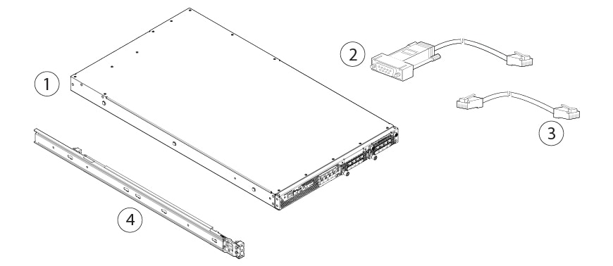
The following table lists the features of the FMC 1000, 2500, and 4500.

Table 1. FMC 1000, 2500, and 4500 Features

Feature

1000

2500

4500

Form factor

1 RU

Rack mount

Yes

Standard 19-in. (48.3 cm) 4-post EIA rack

Airflow

Front to rear

Cold aisle to hot aisle
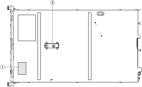
Asset pullout card

Yes

Displays serial number

Grounding hole

Yes

Use is optional. The supported AC power supplies have internal grounding, so no additional chassis grounding is required.
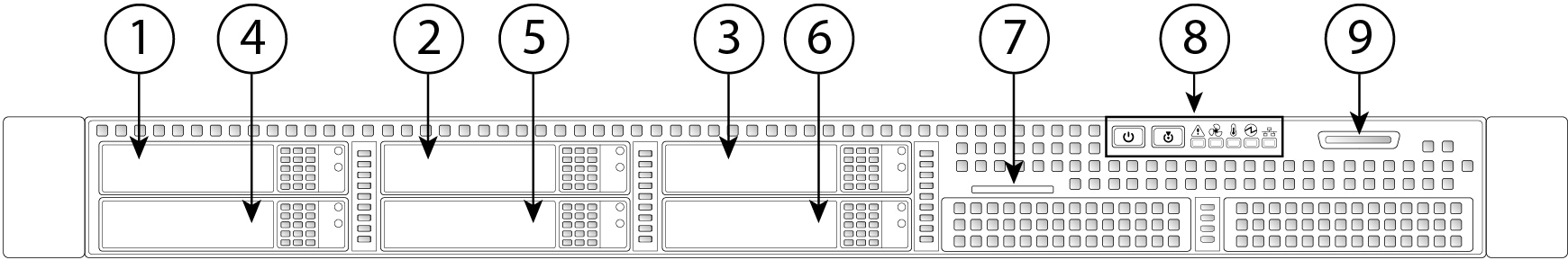
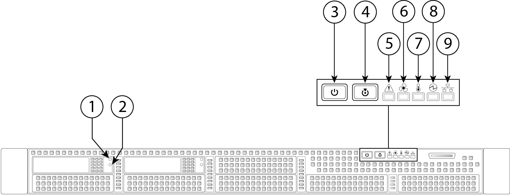
Locator beacon

Yes

Power switch

Yes

Processor

1 Intel E5-2620 V4 CPU

2 Intel E5-2620 V4 CPUs

2 Intel E5-2640 V4 CPUs

Memory

32 GB

64 GB

128 GB

RDIMMs

Four 8-GB DDR4-2400-MHz RDIMMs

Eight 8-GB DDR4-2400-MHz RDIMMs

Eight 16-GB DDR4-2400-MHz RDIMMs
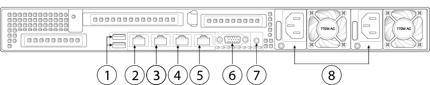
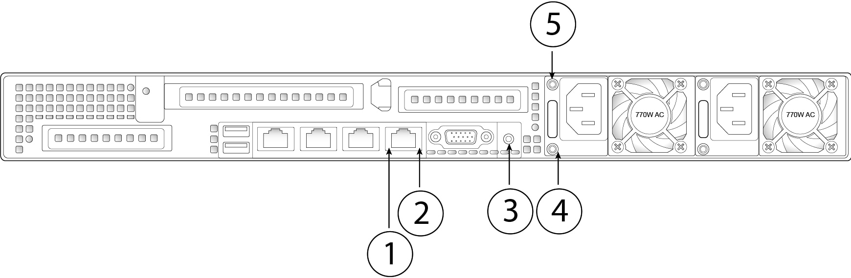
Management ports

1-GB BASE-T Ethernet port (eth0)

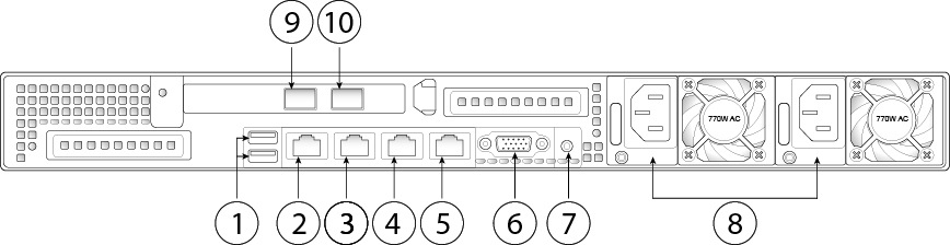
One 1-GB BASE-T Ethernet port (eth0)

Two 10-GB SFP+ ports (eth1 and eth2)

USB ports

2

VGA port

One 3-row 15-pin DE-15 connector

Enabled by default.

SFP ports

2 fixed SFP+ ports

SFP+

FS2K-NIC-SFP

FS4K-NIC-SFP

Serial console port

1-GB RJ-45 serial port running RS-232 (RS-232D TIA-561)

System power

Two 770-W AC power supplies (hot-swappable and redundant as 1+1)

Power consumption

2626 BTU/hr

Fans

6 fans for front-to-rear cooling

Storage

Two 900-GB SAS drives

Four 600-GB SAS drives

Six 800-GB SSDs

Package Contents

The following figure shows the package contents for the FMC 1000, 2500, and 4500. Note that the contents are subject to change and your exact contents might contain additional or fewer items.

Figure 1. Package Contents


1

Chassis

2

RJ-45 to DP9-RS232 console cable (Cisco part number 72-3383-XX)

3

RJ-45 to RJ-45 Cat 5 Ethernet cable, yellow 6-feet long (Cisco part number 72-1482-XX)

4

Cisco 1-RU rail kit (Cisco part number 800-43376-XX)

Serial Number Location

The serial number (SN) for the FMC 1000, 2500, and 4500 is printed on the asset pullout card located on the front panel. For the location of the asset pullout card, see Front Panel.

The serial number is also on a label on the cover of the chassis as shown in the following figure.

Figure 2. Serial Number Location on Cover

1

Serial number label

Front Panel

The following figure shows the front panel features and disk-drive configuration for the FMC 1000. See Front Panel LEDs and Buttons for a description of the LEDs.

Figure 3. FMC 1000 Front Panel Features


1

SAS drive 1

2

SAS drive 2

3

Asset pullout card

4

Control panel LEDs

5

Keyboard, video, and mouse (KVM) port

This port is not supported. Use the VGA and USB keyboard ports instead.

The following figure shows the front panel features and disk-drive configuration for the FMC 2500. See Front Panel LEDs and Buttons for a description of the LEDs.

Figure 4. FMC 2500 Front Panel Features


1

SAS drive 1

2

SAS drive 2

3

SAS drive 3

4

SAS drive 4

5

Asset pullout card

6

Control panel LEDs

7

This port is not supported. Use the VGA and USB keyboard ports instead.

The following figure shows the front panel features and disk-drive configuration for the FMC 4500. See Front Panel LEDs and Buttons for a description of the LEDs.

Figure 5. FMC 4500 Front Panel Features


1

SSD drive 1

2

SSD drive 2

3

SSD drive 3

4

SSD drive 4

5

SSD drive 5

6

SSD drive 6

7

Asset pullout card

8

Control panel LEDs

9

This port is not supported. Use the VGA and USB keyboard ports instead.

Front Panel LEDs and Buttons

The following figure shows the front panel LEDs, buttons, and their descriptions for the FMC 1000, 2500, and 4500.

Figure 6. Front Panel LEDs and Buttons


1

Disk-drive fault LED

  • Unlit—The hard drive is operating properly.

  • Amber—Drive fault detected.

  • Amber, flashing—The device is rebuilding.

  • Amber, flashing in 1-second intervals—Drive locate function activated.

2

Disk-drive activity LED

  • Unlit—There is no hard drive in the hard drive tray (no access, no fault).

  • Green—The hard drive is ready.

  • Green, flashing—The hard drive is reading or writing data.

3

Power button/power status LED

  • Unlit—There is no AC power to the appliance.

  • Amber—The appliance is in standby power mode.

  • Green—The appliance is in main power mode. Power is supplied to all appliance components.

4

Unit identification button/LED

  • Unlit—The unit identification function is not in use.

  • Blue—The unit identification function is activated.

5

System status LED

  • Green—The appliance is running in normal operating condition.

  • Green, flashing—The appliance is performing system initialization and memory check.

  • Amber—The appliance is in a degraded operational state. For example:

    • Power supply redundancy is lost.

    • CPUs are mismatched.

    • At least one CPU is faulty.

    • At least one DIMM is faulty.

    • At least one drive in a RAID configuration failed.

  • Amber, flashing—The appliance is in a critical fault state. For example:

    • Boot failed.

    • Fatal CPU and/or bus error is detected.

    • The appliance is in an over-temperature condition.

6

Fan status LED

  • Green—All fans are operating properly.

  • Amber—One or more fans breached the critical threshold.

  • Amber, flashing—One or more fans breached the unrecoverable threshold.

7

Temperature status LED

  • Green—The appliance is operating at normal temperature.

  • Amber—One or more temperature sensors breached the critical threshold.

  • Amber, flashing—One or more temperature sensors breached the unrecoverable threshold.

8

Power supply status LED

  • Green—All power supplies are operating normally.

  • Amber—One or more power supplies are in a degraded operational state.

  • Amber, flashing—One or more power supplies are in a critical fault state.

9

Network link activity LED

  • Unlit—The Ethernet link is idle.

  • Green—One or more Ethernet ports are link-active, but there is no activity.

  • Green, flashing—One or more Ethernet ports are link-active with activity.

Rear Panel

The following figure shows the rear panel of the FMC 1000.

Figure 7. FMC 1000 Rear Panel


1

2 USB keyboard ports

You can connect a keyboard, and along with a monitor on the VGA port, you can access the console.

2

CIMC interface (labeled "M")

This interface is not supported.

3

Serial console port

This port is disabled by default; use the VGA port and keyboard USB port instead.

4

eth0 management interface (labeled "1")

Gigabit Ethernet 10/100/1000 Mbps interface, RJ-45

eth0 is the default management interface.

5

eth1 management interface (labeled "2")

Gigabit Ethernet 10/100/1000 Mbps interface, RJ-45

6

VGA interface

Enabled by default.

7

Unit identification button/LED

8

Two 770-W AC power supplies


Note

Although the Cisco Integrated Management Controller (CIMC) is not supported on the FMC, you can use Lights-Out-Management (LOM) on the default management interface (eth0) on a Serial Over LAN (SOL) connection to remotely monitor or manage the FMC system. For information about using LOM and SOL, see the Firepower Management Center Getting Started Guide for your model.


The following figure shows the rear panel of the FMC 2500 and 4500.

Figure 8. FMC 2500 and 4500 Rear Panel


1

2 USB keyboard ports

You can connect a keyboard, and along with a monitor on the VGA port, you can access the console.

2

CIMC interface (labeled "M")

This interface is not supported.

3

Serial console port

This port is disabled by default; use the VGA port and keyboard USB port instead.

4

eth0 management interface (labeled "1")

Gigabit Ethernet 10/100/1000 Mbps interface, RJ-45

eth0 is the default management interface.

5

eth1 management interface (labeled "2")

Gigabit Ethernet 10/100/1000 Mbps interface, RJ-45

6

VGA interface

Enabled by default.

7

Unit identification button/LED

8

Two 770-W AC power supplies

9

eth2 management interface

10-Gigabit Ethernet SFP+ support

Note 
Use only Cisco-supported SFP+ transceivers.

10

eth3 management interface

10-Gigabit Ethernet SFP+ support

Note 
Use only Cisco-supported SFP+ transceivers.

Rear Panel LEDs and Buttons

The following figure shows the rear panel LEDs and buttons:

Figure 9. Rear Panel LEDs and Buttons


1

Interface link speed LED

Located to the left of each port.

  • Unlit—Link speed is 10 Mbps.

  • Amber—Link speed is 100 Mbps.

  • Green—Link speed is 1 Gbps.

2

Interface link status LED

Located to the right of each port.

  • Unlit—No link is present.

  • Green—Link is active.

  • Green, flashing—Traffic is present on the active link.

3

Unit identification button/LED

  • Unlit—The unit identification LED is not in use.

  • Blue—The unit identification LED is activated.

4

Power supply status LED

  • Unlit—No AC input (12-V main power off, 12-V standby power off).

  • Green, flashing—12-V main power off; 12-V standby power on.

  • Green—12-V main power on; 12V standby power on.

  • Amber, flashing—Warning detected but 12-V main power on.

  • Amber—Critical error detected; 12-V main power off.

5

Power supply fault LED

  • Unlit—The power supply is operating normally.

  • Amber, flashing—An event warning threshold has been reached, but the power supply continues to operate.

  • Amber—A critical fault threshold has been reached, causing the power supply to shut down (for example, a fan failure or an over-temperature condition).

Power Supply

The following table lists the specifications for each 770-W AC power supply (Cisco part number FMC-PWR-AC-770W) used in the FMC 1000, 2500, and 4500.

Table 2. Power Supply Specifications

Description

Specification

Power consumption

1313 BTU/hr

AC input voltage range

Nominal range: 100–120 V AC, 200–240 V AC

Range: 90–132 V AC, 180–264 V AC

AC input frequency

Nominal range: 50–60 Hz

Range: 47–63 Hz

Maximum AC input current

9.5 A peak at 100-V AC

4.5 A peak at 208 V-AC

Maximum input volt amperes

950 VA at 100-V AC

Maximum output power for each power supply

770 W

Maximum inrush current

15 A (subcycle duration)

Maximum hold-up time

12 ms at 770 W

Power supply output voltage

12-V DC

Power supply standby voltage

12-V DC

Efficiency rating

Climate Savers Platinum Efficiency (80 Plus Platinum certified)

Form factor

RSP2

Input connector

IEC320 C14

Hardware Specifications

The following table lists the hardware specifications for the FMC Center 1000, 2500, and 4500.

Table 3. FMC 1000, 2500, and 4500 Hardware Specifications

Specification

1000

2500

4500

Physical

Form factor

1 RU

Rack mountable

Yes

Standard 19-in. (48.3 cm) 4-post EIA rack

Dimensions (H x W x D)

1.7 x 16.9 x 29.8 in. (4.3 x 42.9 x 75.9 cm)

Weight (fully loaded chassis)

32.2 lb (16.6 kg)

34.1 lb (16.8 kg)

36.0 lb (17.0 kg)

Airflow

Front to rear (cold aisle to hot aisle)

Fans

6 fans for front-to-rear cooling

Storage

SAS

Two 900 GB

RAID 1, 2.5 in., 10-K RPM, 4Kn, hot-swappable

Four 600 GB

RAID 5, 2.5 in., 10-K RPM, 4Kn, hot-swappable

SSD

Six 800 GB

RAID 6, 2.5 in., 10-K RPM, 4Kn, hot-swappable

Memory

RDIMMs

32 GB

Four 8-GB DDR4-2400-MHz

64 GB

Eight 8-GB DDR4-2400-MHz

128 GB

Eight 16-GB DDR4-2400-MHz

Power

System power

Two 770-W AC power supplies

Power consumption

2626 BTU/hr

Redundant power supplies

Yes

Hot-swappable and redundant as 1+1

Environmental

Temperature

Operating: 41 to 95°F (5 to 35°C) Derate the maximum temperature by 1°C per every 305 meters of altitude above sea level.

Nonoperating: –40 to 149°F (–40 to 65°C) when the appliance is stored or transported

Humidity (RH)

10 to 90 % noncondensing

Altitude

Operating: 0 to 10,000 ft

Nonoperating: 0 to 40,000 ft when the appliance is stored or transported

Sound power level

5.4 Bels (Measure A-weighted per ISO7779 LwAd)

Operation at 73°F (23°C)

Sound pressure level

37 Bels (Measure A-weighted per ISO7779 LwAd)

Operation at 73°F (23°C)

Product ID Numbers

The following table lists all of the Product IDs (PIDs) spares associated with the FMC 1000, 2500, and 4500.

Table 4. FMC 1000, 2500, and 4500 PIDs

PID

Description

FMC-PWR-AC-770W=

Cisco AC power supply 770-W

FMC1K-HDD-900G=

Cisco FMC 900-GB 12-GGB 10-K 2.5-inch SAS

FMC2K-HDD-600G=

Cisco FMC 600-GB 12-GGB 10-K 2.5-inch SAS

FMC4K-SSD-800G=

Cisco 800-GB 12-Gbps SAS SSD

UCSC-RAILB-M4=

Ball bearing rail kit

Power Cord Specifications

Each power supply has a separate power cord. Standard power cords or jumper power cords are available for connection to the appliance. The jumper power cords for use in racks are available as an optional alternative to the standard power cords.

If you do not order the optional power cord with the system, you are responsible for selecting the appropriate power cord for the product. Using a incompatible power cord with this product may result in electrical safety hazard. Orders delivered to Argentina, Brazil, and Japan must have the appropriate power cord ordered with the system.


Note

Only the approved power cords or jumper power cords provided with the appliance are supported.


The following power cords are supported.

Figure 10. Argentina CAB-250V-10A-AR

1

Plug: IRAM 2073

2

Cord set rating: 10 A, 250 V

3

Connector: IEC 60320/C13

Figure 11. Australia CAB-9K10A-AU

1

Plug: A.S. 3112-2000

2

Cord set rating: 10 A, 250 V

3

Connector: IEC 60320/C15

Figure 12. Brazil PWR-250V-10A-BZ

1

Plug: NBR 14136

2

Cord set rating: 10 A, 250 V

3

Connector: IEC 60320/C13

Figure 13. Cabinet Jumper CAB-C13-C14-2M

1

Plug: SS10A

2

Cord set rating: 10A, 250V

3

Connector: HS10S

Figure 14. Cabinet Jumper CAB-C13-C14-AC

1

Plug: SS10A

2

Cord set rating: 10 A, 250 V

3

Connector: HS10S

Figure 15. Cabinet Jumper CAB-C13-CBN

1

Plug: SS10A

2

Cord set rating: 10 A, 250 V

3

Connector: HS10S

Figure 16. China CAB-250V-10A-CH

1

Plug: GB2099.1/2008

2

Cord set rating: 10 A, 250 V

3

Connector: IEC 60320/C13

Figure 17. Europe CAB-9K10A-EU

1

Plug: CEE 7/7 (M2511)

2

Cord set rating: 10 A/16 A, 250 V

3

Connector: IEC 60320/C15 (VSCC 15)

Figure 18. India CAB-250V-10A-ID

1

Plug: IS 6538-1971

2

Cord set rating: 16A, 250V

3

Connector: IEC 60320-C13

Figure 19. Israel CAB-250V-10A-IS

1

Plug: SI-32

2

Cord set rating: 10A, 250V

3

Connector: IEC 60320-C13

Figure 20. Italy CAB-9K10A-IT

1

Plug: CEI 23-16/VII (I/3G)

2

Cord set rating: 10 A, 250 V

3

Connector: IEC 60320/C15

(EN 60320/C15M)

Figure 21. Japan CAB-JPN-3PIN

1

Plug: JIS 8303

2

Cord set rating: 12 A, 125 V

3

Connector: IEC 60320/C13

Figure 22. Japan CAB-C13-C14-2M-JP

1

Plug: EN 60320-2-2/E

2

Cord set rating: 10 A, 250 V

3

Connector: EN 60320/C13

Figure 23. North America CAB-9K12A-NA

1

Plug: NEMA5-15P

2

Cord set rating: 13 A, 125 V

3

Connector: IEC 60320/C15

Figure 24. North America CAB-N5K6A-NA

1

Plug: NEMA6-15P

2

Cord set rating: 10 A, 125 V

3

Connector: IEC 60320/C13

Figure 25. North America CAB-AC-L620-C13

1

Plug: NEMA L6-20 (molded twist lock)

2

Cord set rating: 13 A, 250 V

3

Connector: IEC 60320/C13

Figure 26. Switzerland CAB-9K10A-SW

1

Plug: SEV 1011 (MP232-R)

2

Cord set rating: 10 A, 250 V

3

Connector: IEC 60320/C15

Figure 27. United Kingdom CAB-9K10A-UK

1

Plug: BS1363A/SS145

2

Cord set rating: 10 A, 250 V

3

Connector: IEC 60320/C15