Maintain and Monitor Cisco Cyber Vision

Monitored presets

A monitored preset is a preset that is monitored against a baseline. To monitor your network using Cisco Cyber Vision Center, you must set up monitored presets.

On the Explore page, you can select a preset to view the network data that matches the preset definition. You can also export the data as a PDF file.

Presets

A preset is a customizable view that allows you to focus on specific subsets of network data. A preset filters network data based on defined criteria and gives you a focused view of an organizational network for quick, meaningful analysis.

The parameters that you can configure for a preset include:

  • Time

  • Risk score range

  • Networks, by IP subnets or VLAN IDs

  • Device tags

  • Activity tags

  • Groups

  • Sensors

Baselines

A baseline is a snapshot of a preset. It is the reference point against which network behavior is periodically compared to detect network deviations or anomalies, such as new devices, altered communications, or unusual activities that may indicate security issues or operational problems.

Multiple baselines for a preset

You can create multiple baselines for a preset to monitor various known states of your network.

For example, network activity baselines may differ for weekdays and weekends. Create two baselines for these scenarios, and activate the baseline that accurately monitors your network on any given day.

To activate one of multiple baselines for a monitored preset, refer to Configure monitored presets.

Create a baseline

Establish a baseline for a preset to monitor and track network activity in Cisco Cyber Vision Center.

Follow these steps to create a baseline for a preset.

Procedure


Step 1

From the main menu, select Explore.

Step 2

Select the Create baseline icon for a preset from one of the following locations:

  • The preset dashlet listed on the Explore page.

  • The preset details page displayed when you select a preset dashlet.

Step 3

Enter a name and description for the preset.

Step 4

Click Create.


The baseline is created. You can view it from the Monitor page in Cisco Cyber Vision Center, where all available baselines are displayed and categorized by their respective presets.

Configure monitored presets

Configure a monitored preset to define the interval for checking the network and the types of event differences for which you want to view alerts.

Any differences between the selected baseline and the current network status result in alerts that you can review and acknowledge.

Before you begin

A monitored preset is a preset with a baseline. Refer to Create a baseline.

Procedure


Step 1

From the main menu, select Monitor.

Step 2

For each monitored preset that you want to configure, click the vertical ellipsis, then select Monitored preset settings.

Step 3

Configure the monitored preset.

  1. Enter the monitoring interval in seconds.

  2. If you created more than one baseline for the preset, select the baseline that you want to activate in the Monitored baseline field.

  3. In the Events severity section, select the severity level for alerts generated for each event type.

  4. In the Advanced settings section, select the component, property, and activity differences for which you want to view alerts.

  5. Click OK.


Manage monitored preset differences

Acknowledge or report a single monitored preset difference entry.

Acknowledge an entry to mark a reported event as normal for the network. Report an entry to identify a reported event as an anomaly and create an event in Cisco Cyber Vision Center.

After you select a baseline on the Monitor page, you can use the following bulk-management options:

  • To acknowledge all differences across the components and activities, click the check mark in the left pane.

  • To acknowledge or report multiple, specific differences in the components or activities listings, select the entries and then select Acknowledge Selection or Report Selection.

Procedure


Step 1

From the main menu, select Monitor.

Step 2

In the What changed area, select the baseline that you want to examine for a monitored preset.

Step 3

View the reported differences.

Differences are reported based on one of the following categories:

  • New components

  • New activities

Step 4

To view the communication flows that may have caused the reported difference, click an entry to view its details, and then click the Investigate with flows link.

Step 5

In the components list, click an entry to view its details.

You can choose from the following four options:

Table 1. Component actions

Action

Definition

Acknowledge Component

You can enter a message explaining your choice for reference. You have two acknowledgement options:

  • Acknowledge and include: Retain this alert and receive new alerts if something new happens with this component or activity.

  • Acknowledge and keep warning: Delete this alert and receive new alerts if the same event repeats.

Ack. with related activities

You can enter a message explaining your choice for reference.

Select Acknowledge and include to retain the alert and receive alerts for any new events for the component and its activities.

Report component

You must enter a message explaining your choice for reference. You continue to receive alerts if the anomaly is detected again.

Select Report component to create an event report for this anomaly.

Show details

View device tags and properties.

Step 6

In the activities list, click an entry to view its details.

You can choose from the following three options:

Table 2. Activity actions

Action

Definition

Acknowledge activity

Acknowledge the reported event as normal for the network. You can enter a message explaining your choice for reference. Two acknowledgement options are available:

  • Acknowledge and include: Retain this alert and receive alerts if something new happens with this component or activity.

  • Acknowledge and keep warning: Delete this alert and receive a new alert if the same event repeats.

Report activity

You must enter a message explaining your choice for reference. You continue to receive alerts if the anomaly is detected again.

Select Report activity to create an event report for this anomaly.

Show details

View activity tags and variables.


Center shutdown/reboot

A center shutdown/reboot capability is a Cisco Cyber Vision feature that enables administrators to trigger a safe shutdown or reboot of the Center.

Use the Rebootfunction to resolve minor bugs, including system overload events, without requiring a full shutdown.

You can access the center shutdown/reboot capability from the Cisco Cyber Vision main menu by navigating to Admin > System.

Upgrade with a combined update file

Use a combined update file to update the Cisco Cyber Vision Center and applicable sensors.

Version releases include a Cisco Cyber Vision Manual Update Center update file.


Important


Rolling back to an earlier Cisco Cyber Vision version is not supported.


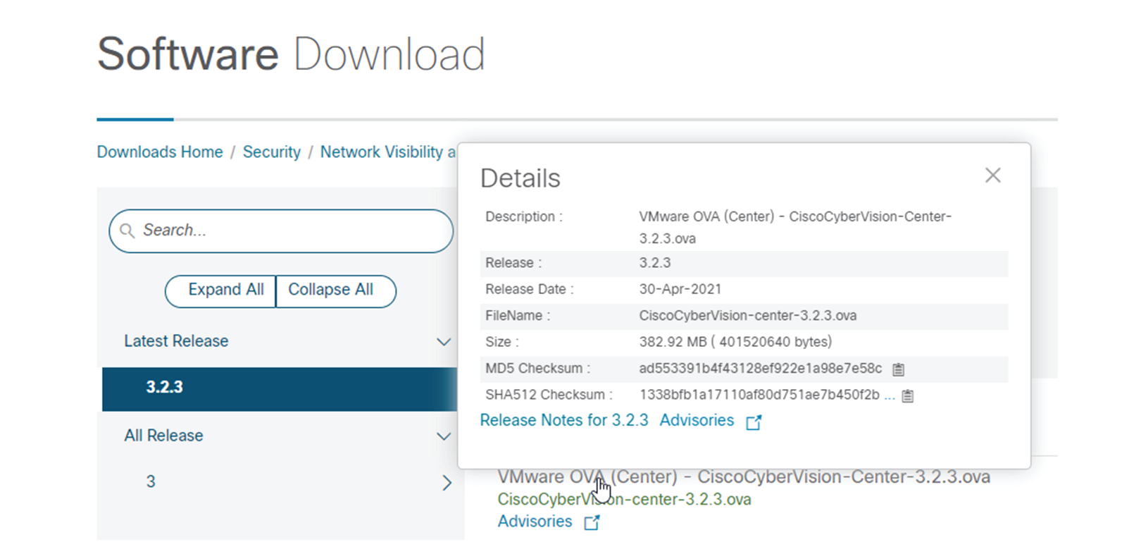
Use the SHA512 checksum provided by Cisco to verify that the downloaded file is healthy.

Procedure


Step 1

Retrieve the Cisco Cyber Vision combined update from cisco.com.

Step 2

On Windows, open a shell prompt, such as Windows PowerShell, and run the following command to retrieve the file checksum:

Example:

Get-FileHash .\CiscoCyberVision-<TYPE>-<VERSION>.<EXT> -Algorithm SHA512 | Format-List

Step 3

On cisco.com, hover over the file and copy the SHA512 checksum.

Step 4

Compare the two checksums.

  • If the checksums are identical, the file is healthy.

  • If the checksums do not match, download the file again.

  • If the checksums still do not match, contact Cisco support.

Step 5

Log in to Cisco Cyber Vision.

Step 6

Choose Admin > System from the main menu, and then click System update.

Step 7

Select the CiscoCyberVision-update-combined-<VERSION>.dat update file.

Step 8

Confirm the update.

As the Center and sensors update, a holding page appears. When the update is complete, select Center Reboot. You are logged out.

Step 9

Log in to Cisco Cyber Vision.

If sensors were offline when the update occurred, repeat this procedure until all sensors update.


Syslog configurations

A syslog configuration is a network logging setup that

  • forwards Cyber Vision events and alerts to an external syslog server,

  • enables integration with Security Information and Event Management (SIEM) platforms, and

  • supports Common Event Format (CEF) for standardized message structure.

Table 3. Feature History Table

Feature

Release Information

Feature Description

Non-CEF syslogs support removed

Release 5.3.x

You can no longer use non-CEF syslog formats with Cyber Vision Center.

When you upgrade to Cisco Cyber Vision Center Release 5.3.x, any existing syslog connections that use non-CEF formats are automatically updated to CEF formats.

Configure syslog

Enable forwarding of Cyber Vision events and alerts to an external syslog server to integrate with a Security Information and Event Management (SIEM) system.

To configure syslog, follow these steps:

Before you begin

  • Ensure you have administrator access to Cyber Vision Center.

  • Confirm that the external syslog server is accessible. Obtain the host IP address, port, and the required protocol.

  • If secure communication is required, ensure you have the P12 certificate from your SIEM administrator.

  • Recent syslog format changes:

    • Standard and RFC3164 formats are deprecated.

    • Standard/CEF is now named CEF.

    • RFC3164/CEF is now named CEF Extended Time Precision.


    Note


    If the deployment had Standard or RFC3164 formats configured, version 5.3.x setup migrates the configuration to CEF.


Procedure


Step 1

From the main menu, choose Admin > System.

Step 2

Click Configure in the Syslog configuration menu.

Step 3

Select Protocol.


Note


If secure communication is required, select TCP + TLS and import the P12 certificate.


Step 4

Enter the syslog server Host IP address and Port that are accessible from Cyber Vision Center.

Step 5

Select the required Format.

  • CEF: This format, based on the Common Event Format (CEF) standard, sends events with second-precision timestamps.

  • CEF Extended Time Precision: This format, based on the Common Event Format (CEF) and an extended syslog header, sends events with millisecond-precision timestamps.

Step 6

Save the configuration.


Cyber Vision Center sends events from the Classic UI to syslog with 'Version Number = 1.0.' It sends alerts from the New UI to syslog with 'Version Number = 2.0.

What to do next

To configure notifications for specific alert types, see "Enable or disable syslog notifications for alert types" in the Cisco Cyber Vision New UI Administrator Guide.

To export events using syslog, see "Configure event export to syslog (Classic UI)" in the Cisco Cyber Vision Syslog Notification Format Configuration Guide.

Database import and export

The Import/Export feature is a system administration tool that allows for the management of the Cisco Cyber Vision database.

  • Supports database backups for industrial network data.

  • Facilitates database transfers between different Center instances.

  • Retains network data, events, users, and customizations such as groups and component names.

Database management

To access the Import/Export page, choose Admin > System from the main menu.

Following are constraints and requirements for database operations:

  • Database export size is limited to 2 GB to prevent performance issues.

  • If the database exceeds 2 GB, connect via SSH and use the sbs-db dump command.

  • Only configurations created in the Cisco Cyber Vision GUI persist during transfers.

  • When changing a Center , perform a basic configuration of the new Center before reconfiguring Cisco Cyber Vision. Refer to the corresponding Center Installation Guide.


Note


The Import process may take one hour for big databases. Refresh the page to check that the import remains active (i.e., no error message).


Update the Knowledge DB

Update the internal Cisco Cyber Vision database that contains recognized vulnerabilities, icons, and threats.


Important


To remain protected against vulnerabilities, always update the Knowledge DB in Cisco Cyber Vision as soon as possible after notification of a new version.


Procedure


Step 1

Download the latest.db file available from cisco.com.

Step 2

From the main menu, choose Admin > System.

Step 3

Click Import a Knowledge DB under the Knowledge DB field.

Step 4

Select the file, and then click Open to upload the file.

Importing the new database rematches your existing components against any new vulnerabilities and updates the network data.


Certificate fingerprints

A certificate fingerprint is a unique identifier that

  • identifies a digital certificate,

  • verifies the authenticity of certificates during enrollment and renewal, and

  • enables secure communication between Global Centers and synchronized Centers.

Validity and renewal

Use the fingerprint during enrollment with a Global Center or when updating after certificate renewal. The fingerprint validates the certificate and authorizes secure connectivity with remote hosts. For more information on Global Center, see Information and characteristics.

Certificates are valid for 2 years. Upon expiration, renewal and fingerprint exchange typically occur automatically. If automatic renewal fails, perform a manual renewal and provide the new fingerprint to the Global Center. This action restores enrollment and connectivity statuses in the Global Center. See the the Centers Installation Guides for detailed instructions.


Note


Always ensure the fingerprint matches the current certificate to maintain secure connections.


Disable Cisco Cyber Vision telemetry

Telemetry monitors your system and provides anonymous diagnostics and usage data to help Cisco understand and enhance product usage. Telemetry data communication occurs as HTTPS traffic through Port 443 with connectdna.cisco.com.

Telemetry is enabled by default.

Follow these steps to disable Cisco Cyber Vision telemetry.

Procedure


Step 1

From the main menu, choose Admin > System.

Step 2

Under Telemetry Collection, click the ON toggle.

The toggle turns OFF.


Reset to Factory Defaults

The Reset to Factory Defaults is a system recovery operation that reverts the application to its initial state.

  • Requires as a last resort usage after all other troubleshooting attempts fail.

  • Deletes GUI configuration, sensor data, and sensor configurations.

  • Persists root password, certificates, and basic configuration settings.

Impact on system defaults

To access the Reset function, choose Admin > System from the main menu.

A Reset to Factory Defaults deletes the following:

  • Some Center configuration data elements.

  • The GUI configuration (such as user accounts, the setup of event severities, etc.).

  • Data collected by the sensors.

  • The configuration of all known sensors (such as IP addresses, capture modes, etc.).


Note


Get help from product support before proceeding.


Post-Reset Behavior

After a Reset to Factory Defaults occurs, the GUI refreshes with the installation wizard. See the corresponding Center Installation Guide .

Snort

A Snort instance is a network intrusion detection system (NIDS) that

  • analyzes network traffic for malicious activity using a rule matching engine,

  • applies a set of rules that characterize potentially harmful network activity, and

  • integrates with Cisco Cyber Vision to provide real-time intrusion detection alerts and management.

Table 4. Feature History Table

Feature

Release Information

Feature Description

Enable or disable Snort on a Center DPI interface

Release 5.3.x

You can enable or disable Snort IDS or IPS on a Cisco Cyber Vision Center DPI interface. Previously, Snort was always enabled by default and could not be changed.

Additional reference information

  • Cisco Cyber Vision can run the Snort engine on the Center and compatible sensors. The Center manages rule configuration and distribution. It also intercepts alerts for display in the GUI.

  • Snort is disabled by default on sensors. To enable it, activate features of the Intrusion Detection System (IDS). See Enable IDS on a sensor.

  • On the Center’s Deep Packet Inspection (DPI), Snort is enabled by default.

  • Snort is available on the following Cisco devices:

    • Cisco IC3000 Industrial Compute Gateway

    • Cisco Catalyst 9300 Series Switches

    • Cisco IR8340 Integrated Services Router Rugged

    • It is also available by default on the Center DPI.

Snort rulesets and rule categories

The Snort rules are organized into two main rulesets: the Community ruleset and the Subscriber ruleset.

Community ruleset

  • Distributed freely and certified by Talos, including rules contributed by the open source community and integrators.

  • Represents a subset of the full ruleset available to subscribers.

  • Does not include the most recent Snort rules and does not guarantee coverage against the latest threats.

Subscriber ruleset

  • Contains all rules released by the Talos Security Intelligence and Research Team.

  • Provides rapid access to the newest rules and early coverage of exploits and vulnerabilities.

  • Remains aligned with ongoing Talos research for maximum detection capability.

  • Requires Advantage licensing and an IDS sensor license for each enabled sensor.

Snort rules are organized into categories, each targeting a specific threat type or platform.

Table 5. Rule categories

Category

Description

Browser

Detects vulnerabilities in major browsers (e.g., Chrome, Firefox, Internet Explorer) and browser plugins such as ActiveX.

Deleted

Contains deprecated or replaced rules.

Experimental–DoS

Rules targeting Denial of Service (DoS) activities such as TCP SYN flooding or DNS/HTTP flooding.

Experimental–Scada

Detects attacks on industrial control system assets.

Exploit–Kit

Tailored to identify exploit kit activities.

File

Addresses vulnerabilities in various file types (executables, Microsoft Office, images, Java, PDF, etc.).

Malware–Backdoor

Identifies traffic to known backdoor command channels.

Malware–CNC

Detects botnet command and control activity (call home, data exfiltration, download of dropped files).

Malware–Other

Covers other malicious tools or miscellaneous malware activity.

Misc

Rules address protocol-specific threats, policy violations such as spam and unwanted applications, and indicators not categorized elsewhere.

OS–Other

Looks for vulnerabilities in various operating systems (Linux, mobile OS, Solaris, etc.).

OS–Windows

Targets vulnerabilities in Windows operating systems.

Server–Other

Deals with vulnerabilities in multiple server types (web servers, database servers, mail servers, etc.).

Server–Webapp

Pertains to attacks against server-based web applications.

Snort rules management features

The Snort rules management system in Cisco Cyber Vision Center includes these features:

Table 6. Snort rules management

Feature

Description

Snort community rules

Snort community rules are set by default in the Cyber Vision Center.

Subscriber rules

Click Use Subscriber Rules from the Admin > Snort page to enable snort subscriber rules (requires Advantage and intrusion detection system (IDS) sensor licenses).

Category-based management

Enable or disable entire rule categories via the GUI.

Direct rule file download

Download rule files per category from the interface.

Individual rule control

Enable or disable specific rules within categories, independent of category status.

In the downloaded rule files, locate the rule and get the sid (signature id). Go to Admin > Snort and enter it in the Rule sid and click Disable or Enable.

Custom rule import

Import and manage user-created rules via the IMPORT CUSTOM RULES FILE function from the Admin > Snort page.

Rule synchronization

Apply synchronized rule sets to sensors using the Synchronize rules on sensors feature from the Admin > Snort page.

Reset to default

Click RESET TO DEFAULT from the Admin > Snort page to restore the entire rule configuration to factory defaults and remove all custom rule files.

Enable IDS on a sensor

Enable Intrusion Detection System (IDS) on a compatible Cisco sensor to activate Snort-based intrusion detection.

Use this task to activate Snort's intrusion detection capabilities on a supported Cisco sensor for network security monitoring.

Before you begin

Ensure that your sensor is one of the following compatible devices: Cisco IC3000 Industrial Compute Gateway; Cisco Catalyst 9300 Series Switch; Cisco IR8340 Integrated Services Router Rugged; or Center DPI Interface.

Procedure


Step 1

From the main menu, choose Admin > Sensors > Sensor Explorer.

Step 2

Select the sensor on which you want to enable IDS.

Step 3

Click Enable IDS.


IDS is active on the selected sensor. Snort monitors network traffic for threats.

What to do next

If required, you can disable Snort's intrusion detection capabilities. To do this, select the sensor and select Disable IDS.

Risk Score

The Risk score is a configuration setting that allows you to set up the time range used for risk score computation.

  • Enables selection of predefined time ranges including 30 days or 7 days.

  • Supports custom time ranges with a minimum duration of one day.

  • Triggers hourly computation based on the configured activity window.

You can configure the risk score by navigating to Admin > Risk score in the system interface.

For more information about risk scores, see the Risk Score Concept .

Cisco Cyber Vision extensions

A Cisco Cyber Vision extension is an optional add-on to the Center that provides additional features, such as the management of new device types, additional detection engines, or integrations with external services.

From the Extensions page, you can manage Cisco Cyber Vision extensions.

Available extension

Currently, the following extensions are available:

  • Cyber Vision sensor management

    For more information about this extension and how to use it, refer to Sensors.

  • Cyber Vision Reports Management

    For more information about this extension and how to use it, refer to Reports.