Configure Cisco Cyber Vision

Network organizations

A network organization is a network-management interface that

  • enables you to define subnetworks within an industrial network by setting up ranges of IP addresses,

  • allows you to specify whether subnetworks are considered internal (OT) or external, and

  • impacts how Cyber Vision manages device licensing, flow storage, and risk assessment.

IP-address classification

In Cyber Vision, all private IP addresses are automatically classified as OT Internal. These addresses appear in the IP Address / subnet column on the Network Organization page. Public IP addresses are considered External by default, except for:

  • Broadcast IPv4: 255.255.255.255

  • IPv4 and IPv6 zero: 0.0.0.0 and 0:0:0:0:0:0:0:0

  • Loopback IPv4 and IPv6: 127.0.0.1 and ::1

  • Link Local Multicast IPv4 and IPv6: 224.0.0.0/8 and ff00::/8

If you need to treat a public IP address as OT Internal, change its network type to add an exception. This is useful for industrial sites that use public IP addresses in private networks. Marking a set of IP addresses as External will:

  • exclude their associated flows from the database,

  • remove their devices from the device license count, and

  • omit them from risk scoring.

Feature history table

Feature

Release Information

Feature Description

Network based auto grouping

Release 5.5.x

The network based auto grouping feature streamlines device management. It automatically organizes devices based on established network definitions. Groups are created and named according to your network names. You can use this feature for easier ISE API integration and device classification.

Define a Subnetwork

Allow precise management and monitoring of devices by defining subnetworks and specifying their characteristics.

Use this task to add a new subnetwork to your network organization. Customize IP ranges, VLANs, and network types to improve device grouping and monitoring.

Before you begin

  • Ensure you have the required IP addresses and subnets.

  • Obtain VLAN ID information if applicable.

Procedure


Step 1

From the main menu, choose Admin > Network Organization.

Step 2

Click Add a network.

Step 3

Enter an IP address range and its subnet in the IP address/subnet field.

Step 4

(Optional) Enter the VLAN ID to enable overlapping networks.

Step 5

Enter the Network name.

Step 6

Select the Network Type (Options include OT Internal, IT Internal, or External).

Select the network type to change Cyber Vision performance, flow storage, device risk scoring, and device license count.

Step 7

Enable Use a device engine option for this network range.

  • If devices share the same IP in the monitored network, select the first option. This prevents grouping components by IP.

  • If identical addressing is used in different subnetworks (for example, production lines), select the second option. In this case, components detected by the same sensor with the same IP are grouped together only if they are seen by the same sensor.

Step 8

Click Add a network to save and apply the new subnetwork.


You have added the subnetwork with the specified IP range, VLAN, network type, and device engine options. This enables accurate grouping and monitoring of network components.

Create network groups

Group your assests automatically according to your network definitions. These groups enable easier device management and allow you to segment your network using Cisco Identity Services Engine (ISE) integration.

Each group is named after its associated network name.

Before you begin

Ensure your network definitions are accurate and complete. From the main menu, choose Admin > Network Organization to review existing definitions.

Procedure


Step 1

From the main menu, choose Admin > Network Organization.

Step 2

Click Create groups based on network.


Note


  • For each defined network, the system creates one group and names it after the Network Name.

  • Loopback, link-local, local unicast, multicast, and broadcast networks are excluded from network groups.


Step 3

Select Yes or No, for the presented options:

  • Automatically assign any newly discovered network devices to the groups.

  • Delete the existing groups.


    Caution


    If you select Yes, all existing network groups and user-defined groups are deleted.

    If you have existing Cisco Identity Services Engine (ISE) and Firewall integrations, be very careful when deleting groups. Deleting groups may disrupt these integrations and affect their operation.


Step 4

Click Submit.


The system creates groups using your network definitions.

What to do next

  • From the main menu, choose Explore. Select any preset and view the groups under the GROUPS tab to see the created groups.

  • Once groups are created based on network definitions, you can synchronize them with Cisco ISE security groups. For integration details, see the “Integrate Cisco Cyber Vision with Cisco Identity Services Engine (ISE)” guide, particularly the "Chapter: Integrate Cisco Cyber Vision and Cisco Identity Services Engine (ISE) through Cisco ISE API".

API Token

Cisco Cyber Vision provides a REST API. To use it you first need to create a token through the API administration page.

A token is a random password which authenticates a request to Cisco Cyber Vision to access or even modify the data in the Center through the REST API. For instance, you can request the latest 10 components detected on Cisco Cyber Vision or create new references. Requests can be used by external applications like a SOC solution.


Note


Best practice: create one token per application so you can remove or expire accesses separately.

To create API token, follow these steps:

  1. From the main menu, choose Admin > API > Token.

  2. Click + New token.

    The Token window appears.

  3. Enter a name.

  4. Use the Status toggle button to disable authorization for the token if you plan to use it later and want to prevent access until then.

  5. Set an Expiration time.

  6. Click Create.

    After the token creation, token appears in the list available on the API page.

  7. Click Show to view the token.

  8. Click copy icon to copy it.

For more information about the REST API refer to the REST API user documentation available on cisco.com.

API Documentation

This page is a simplified API development feature. It contains an advanced API documentation with a list of all possible routes that can be used and, as you scroll down the page to Models, a list of possible data responses (data type, code values and meaning).

In addition to information research, this page allows you to perform basic tests and call the API by sending requests such as GET, DELETE and POST. You will get real results from the Center dataset. Specifications about routes are available such as the route's structure, and parameters and arguments that can be set. An URL is generated and curl can be used in a terminal as it is.

However, for an advanced use, you must create an application that will send requests to the API (refer to the REST API documentation).


Important


All routes other than GET will modify data on the Center. As some actions cannot be reversed, use DELETE, PATCH, POST, PUT with caution.

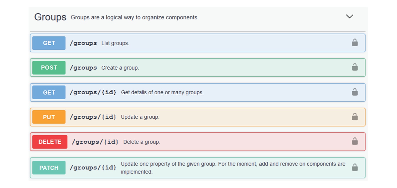
Routes are classified by 's elements type (activities, baselines, components, flows, groups, etc.).

The category "Groups" containing all possible group routes:

To authorize API communications:

Procedure


Step 1

From the main page, choose Admin > API .

Step 2

Click Token to create and/or copy a token.

Step 3

Click Documentation.

Step 4

Click Authorize.

The Available authorizations panel appear.

Step 5

Paste the token in Value field..

Step 6

Click Authorize.

Step 7

Click Close.

Close lockers displays. They indicate that routes are secured and authorization to use them is up.

To use a route:

Step 8

Click a route to deploy it.

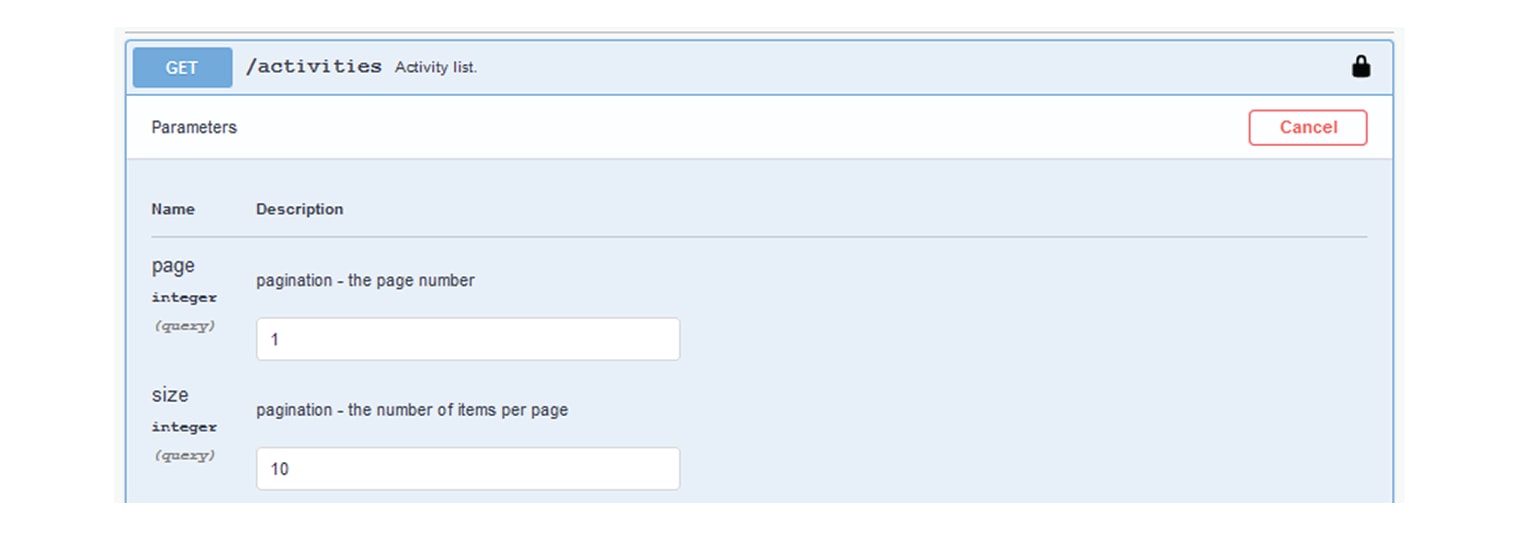
In the example, we choose Get activity list.

Step 9

Click Try it out.

Step 10

You can set some Parameters.

In the example, we set page to 1 and size to 10.

Step 11

Click Execute.


Note


You can only execute one route at a time.

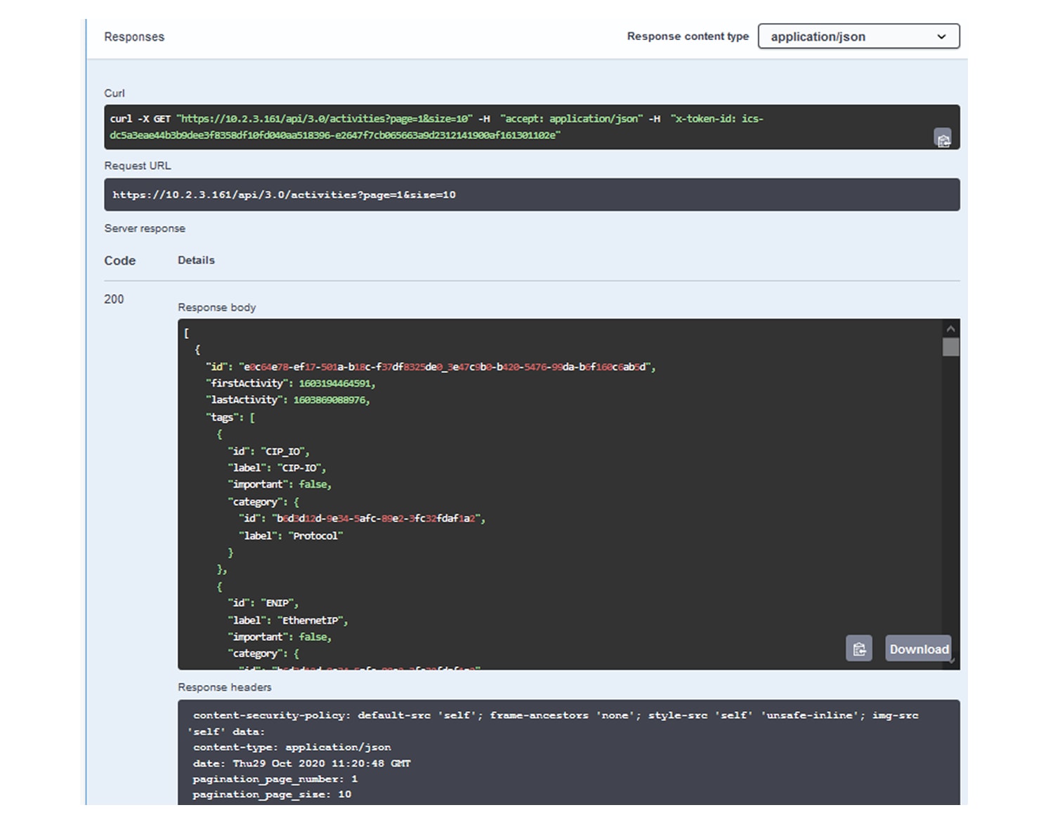
A loading icon appears for a few moments. Responses display with curl, Request URL and the server response that you can copy or even download.

Step 12

When you are finished, click the Authorize button.

Step 13

Log out to clear the token variable, and click Close.


Active Discovery Policies

Active Discovery is used to allow a sensor to send packets to the network to discover previously unseen devices and gather additional properties for known devices.

Active Discovery operates in Broadcast and Unicast, and responses received will be analyzed by Cisco Cyber Vision.

An Active Discovery policy is a list of settings which define protocols and their parameters that will be used to scan the industrial network. The policy will be used in a preset and be applied on a list of sensors and components.

To acces the Active Discovery policies page, choose Admin > Active Discovery > Policies from the main menu.

For more information, refer to the Active Discovery Configuration Guide.

LDAP

Cisco Cyber Vision can delegate user authentication to external services that use LDAP (Lightweight Directory Access Protocol), specifically Microsoft Active Directory and AD LDS services.

To configure an LDAP connection, from the main menu, choose Admin > External Authentication > LDAP.

Configuring LDAP:

LDAP integration can be done through an unencrypted connection, or in a secure way by using certificates for encryption, depending on installation compatibility.

Mapping Cisco Cyber Vision roles with Microsoft Active Directory groups:

User groups available in the external directory can be mapped to Cisco Cyber Vision Product, Operator and Auditor user roles or custom roles. See Users to create custom roles.

Because the Admin user role is exclusively reserved for Cisco Cyber Vision intersnal usage, it cannot be mapped to any external users and thus is not proposed in LDAP settings.

Testing LDAP connection:

After setting up LDAP, the connection between the Cisco Cyber Vision Center and the external directory is to be tested. On the LDAP test connection window, you will use a user login and a password set in the external directory. The Center will attempt to authenticate on the directory server with these credentials. In return, you will get either a successful authentication, or a failed one with an error message.

Login in Cisco Cyber Vision:

When logging into Cisco Cyber Vision, the login format used will determine the base (i.e. internal or external) to be queried:

  • If you use an email, the Cisco Cyber Vision database is queried.

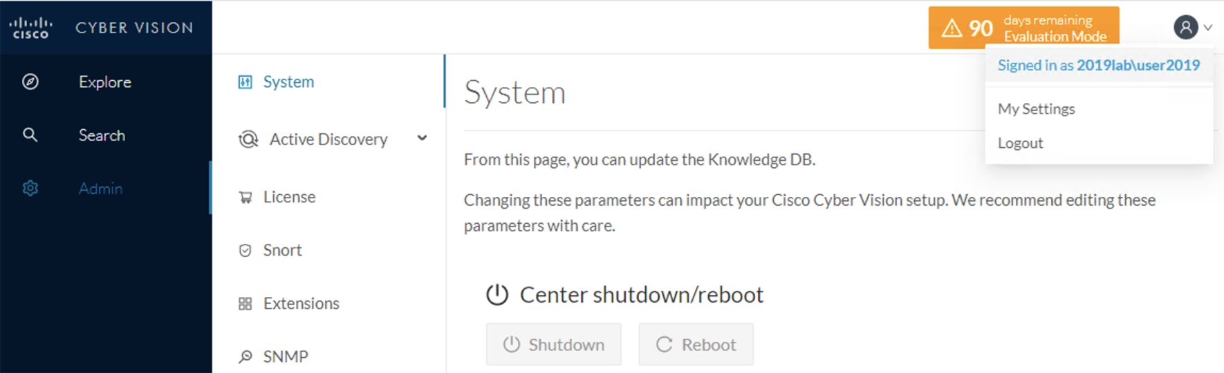
  • If you use the Active Directory format <domain_name>\<user_name> (e.g. cisco\john_doe), then the external directory is used to authenticate users.

Configure LDAP

This taskflow takes you through configuring LDAP in Cisco Cyber Vision using an unencrypted connection or a secure connection.

You can establish two types of secure connections:

  • For a highly secure connection, choose the LDAP over TLS/SSL setting to use a CA-signed certificate with a trust chain. You must upload the certificate into the Center during the configuration task.

  • For internal applications where trust is not a primary concern, choose the Use self signed certificate setting. The Center automatically generates and uses self-signed certificates for this connection type. You don't need to provide a self-signed certificate.

Procedure


Step 1

From the main menu, choose Admin > External Authentication > LDAP .

Step 2

Click New Settings .

Step 3

In the Settings tab,

  1. Choose LDAP over TLS/SSL or Use self signed certificate , or neither.

  2. Enter Primary Server Address and Primary Server Port .

  3. (Optional) Enter Secondary Server Address and Secondary Server Port.

  4. In the Base DN field, enter the distinguished name by which LDAP API recognize this LDAP connection.

  5. (Optional) Check the Modify search filter check box. Then, in the Search Filter field, enter a search filter.

    The default search filter retrieves a user's groups by binding with the user's credentials. You can also modify the filter to target a different attribute, and the specified attribute's value is then used for both group search and binding (login).

    In the Search Filter field, you must include the $user variable. The variable is replaced with the username entered when logging in.

  6. In the Server Response Time field, enter a timeout value, in seconds, after which the Center attempts to connect to the secondary server instead of the primary server.

  7. (Optional) Check the Use Service Account check box. When an LDAP user doesn't have access to their own group, a service account is used. When this setting is enabled, the service account is used to search for and retrieve the user's groups.

    1. Enter a service account username.

    2. Enter a service account password.

  8. If you chose LDAP over TLS/SSL in Step a, a certificate upload field is displayed. Upload or drag-and-drop a PEM file, root or chain certificate.

    The uploaded certificate is displayed at the bottom of the settings page.

Step 4

In the Role Mapping tab,

  1. Map at least one role, default (Product, Operator, or Auditor) or custom, with an Active Directory group. You can create custom roles in the Custom roles area.


    Note


    Enter the exact group names as configured in the remote directory for successful retrieval and mapping to user roles.

    The Admin role is not listed as a default role because it is reserved for Cisco Cyber Vision internal usage and cannot be mapped to external users.


Step 5

Click OK .

Step 6

Click Test connection.

Step 7

Enter the user credentials to test the connection between Cisco Cyber Vision and Active Directory.


Note


For LDAP, the supported username format is <domain_name>\<user_name> (For example, cisco\john_doe).

For LDS, the supported username formats are:

  • <user_name> (For example, john_doe).

  • <email-address> (For example, john@example.com)


Step 8

Click OK .


You can also test the connection by logging out of Cisco Cyber Vision and logging in with different mapped user credentials. The Center menu changes according to the permissions granted to the user.

Single sign-on (SSO)

Single sign-on (SSO) is an authentication mechanism that

  • allows users to access multiple applications using a single set of credentials,

  • reduces the need for multiple logins and password management, and

  • enhances security by centralizing authentication.

Table 1. Feature History Table

Feature

Release Information

Feature Description

SAML 2.0 SSO authentication support

Release 5.3.x

Cisco Cyber Vision Center supports SAML 2.0 SSO authentication.

Central authentication and authorization

This security mechanism uses a central identity provider (IdP) to manage user credentials and access permissions across multiple platforms. It consolidates authentication into a streamlined process.

Federated service provider applications

Applications configured to work with SSO, allowing users to access resources through federated authentication.

Additional reference information

With SSO, a user logs in once to access all authorized service provider applications without re-entering credentials, resulting in improved user experience and streamlined access control.

SAML single sign-on

SAML single sign-on is an authentication approach that:

  • enables users to authenticate once and gain access to multiple applications through a central identity provider,

  • uses Security Assertion Markup Language (SAML) 2.0 to securely exchange authentication and authorization data, and

  • eliminates the need for repeated login credentials for each service.

After successful authentication by the identity provider (IdP), users are redirected back to their service. The browser manages all communication between the service and the IdP. As a result, services such as Cisco Cyber Vision Center do not require a direct network connection to the IdP.

SAML single sign-on integration references

The Cisco Cyber Vision Center supports SAML single sign-on with any single sign-on provider that uses the SAML 2.0 standard, such as the following:

Requirement: SSO configuration for Cisco Cyber Vision Center

Ensure that you meet these requirements when configuring SSO for Cisco Cyber Vision Center:

  • Only admin users authenticated internally can configure SSO.

  • Use only one SSO provider at a time (for example, Azure or Duo).

  • Initiate SSO only from the Cisco Cyber Vision Center, not from the identity provider (IdP).

  • Review audit logs to monitor login and log out events for SSO. The Cyber Vision Center records and sends these events through syslog.

  • Ensure that the Cyber Vision Center host name (FQDN) is DNS resolvable.

    Cisco Cyber Vision generates the SAML Entity ID, Assertion Consumer Service (ACS) URL, and service provider metadata by using the configured Center FQDN. If users access the Center through a reverse proxy or load balancer, the FQDN configured on the Center must match the FQDN that users enter to access the Center.

  • A center can only be configured with SSO if LDAP is disabled or not configured.

  • To prevent authentication conflicts, local user accounts and SSO user accounts must be distinct.

Configure SAML SSO through a reverse proxy

To ensure SAML single sign-on (SSO) works reliably for clients accessing the Cyber Vision Center through a reverse proxy by aligning FQDNs and updating configurations.

The Cyber Vision Center builds its SAML service-provider identity and URLs, including the Entity ID, metadata URL, and Assertion Consumer Service (ACS) URL, from the Center's configured FQDN. These values are not derived from the URL that a user enters in the browser.

When users access the Center through a reverse proxy or load balancer, the Center's configured FQDN must match the public FQDN used by clients.

If the reverse-proxy FQDN differs from the configured Center FQDN, SAML SSO with Microsoft Entra ID (Azure AD) can fail after IdP authentication succeeds. The browser posts the response to https://<Center FQDN>/saml/acs instead of the proxy FQDN, which users cannot reach, so login does not complete.

Before you begin

Ensure that the client machines can resolve the public FQDN used to access Cyber Vision Center.

Configure the reverse proxy to accept the public FQDN in the Host header, present a certificate valid for that FQDN, and forward requests to /saml/acs without redirecting the request or changing its POST body.

Follow these steps to configure SAML SSO through a reverse proxy.

Procedure


Step 1

Check the currently configured Center FQDN.

To display the current Center FQDN, run sbs -config --get fqdn

Step 2

Compare the configured Center FQDN with the public FQDN that users enter in their browser to access the Center through the reverse proxy or load balancer.

Step 3

If the configured Center FQDN and the public FQDN are different, update the Center FQDN: sudo setup-center-cli pki <FQDN>

Replace <FQDN> with the public FQDN that users use to access the Center.

The Center regenerates its internal certificate using the new FQDN.

Step 4

If you changed the Center FQDN, restart the Center services or reboot the Center.

Step 5

Configure the reverse proxy or load balancer:

  • Accept the public FQDN in the Host header.

  • Present a TLS certificate that is valid for the public FQDN.

  • Forward SAML ACS requests to the Center.

  • Forward POST requests to /saml/acs without redirecting them.

  • Preserve the request body when forwarding requests to /saml/acs.

Step 6

Update the SAML service-provider configuration in Microsoft Entra ID:

  1. Import the Center service provider metadata again.

  2. Set Identifier (Entity ID) to https://<FQDN>/saml/metadata. Use the currently configured Center FQDN.

  3. Reply URL to https://<FQDN>/saml/acs. Use the currently configured Center FQDN.


Cyber Vision Center’s SAML service-provider URLs use the public FQDN accessible through the reverse proxy. The Microsoft Entra ID SAML configuration matches these URLs, ensuring reliable single sign-on (SSO).

Single sign-on user accounts

A single sign-on (SSO) user account is a user identity credential that:

  • allows access to multiple applications, systems, or services with a single set of login credentials,

  • uses a central identity provider (IdP) to handle authentication, and

  • simplifies the user experience by removing the need for separate logins for each system.

Role and configuration of SSO accounts

The identity provider (IdP) manages users and groups directly or imports them from external directories such as Active Directory, RADIUS, or LDAP. The IdP sets most account details for SSO users, including usernames and passwords.

A single sign-on account appears on the Cisco Cyber Vision Center users page only after the user has logged in successfully for the first time.

Both single sign-on accounts and the NameID attribute provided by the IdP during SAML login require valid email addresses. By default, many IdPs use the user's username as the NameID attribute. Confirm your IdP's behavior when configuring it and when creating user accounts for SSO access to Cyber Vision Center.

User role mappings for SSO users

Role mappings for SSO users are configuration mappings that:

  • associate user groups from an identity provider (IdP) with roles in the Cyber Vision Center,

  • use role attributes to determine user permissions dynamically, and

  • enable centralized management of user access through SSO integration.

Coordination and configuration details

The following guidelines apply to coordinating with your IdP and managing role attributes:

  • Role assignment: Set up user roles at the Cyber Vision Center and coordinate them with your SSO IdP application settings. Assign roles to groups defined in the IdP.

  • SSO federation understanding: Review how users, groups, and roles are organized in your IdP and configure user role mapping effectively. Consult the IdP vendor documentation for guidance on creating or importing users or groups.

  • Role attribute at the IdP: The IdP sends a role attribute, which lists the groups a user belongs to in the IdP.

  • SSO configuration details: The SSO configuration specifies the name of the role attribute and includes a list of expressions mapped to Cyber Vision Center user roles.

Provide the email address attribute only if you need to migrate local users to SSO. When you configure SSO with the email address attribute, the system identifies the logged-in user's email address from the SAML assertion. If a user exists with that email address, the system removes that user from local authentication. Afterward, the user can only log in with SSO. If needed, create a new internal user.

Microsoft Entra ID single sign-on integrations

A Microsoft Entra ID single sign-on integration is an authentication solution that

  • uses Microsoft’s multi-tenant, cloud-based Azure Active Directory to manage user identities,

  • enables secure and centralized access to both cloud and on-premises applications (such as Cyber Vision Center), and

  • allows users to authenticate with a single account across multiple services through federation.

Within Azure, a tenant is an entity that manages joined devices for one or more organizations. With a single sign-on account, you can access these devices seamlessly. Familiarize yourself with the Azure tenant structure before onboarding applications like Cyber Vision Center.

Add an enterprise application to your Azure tenant

Allow integration of external services or custom apps with your organization's Azure environment.

Before you begin

Procedure

Step 1

Sign in to the Microsoft Entra admin center.

Step 2

From the main page, choose Applications > Enterprise applications > All applications.

Step 3

Select New application and click Create your own application.

Step 4

Enter the application name.

Step 5

Enable Integrate any other application you don't find in the gallery (Non-gallery).

Step 6

Click Create.

Step 7

Enter the display name and select Supported account types.

Step 8

Click Register.


The new application appears in Home > Enterprise applications > All applications.

What to do next

To configure the new application further, open it from Home > Enterprise applications > All applications. For further details, see Configure Azure SSO for Cyber Vision Center.

Configure Azure SSO for Cyber Vision Center

Set up Azure SSO integration so Cyber Vision Center users can authenticate using their Azure Active Directory credentials.

Use this procedure to integrate Cyber Vision Center with Azure SSO. This enables centralized authentication and simplifies role assignments managed via Azure groups.

Before you begin

  • Create the Cyber Vision Center service provider application in Azure. See Add an enterprise application in Azure.

  • Prepare your Azure tenant for integration.

  • Ensure the Cyber Vision Center hostname is a resolvable DNS entry.

  • Verify that usernames and NameID attributes are valid email addresses.

  • You can provide multiple groups. Assign roles to users based on priority.


Note


If Cyber Vision Center offers multiple accessible URLs, SSO users must always use the configured login URL.

The Center FQDN is used to generate the SAML Entity ID and ACS URL. Users must access the Center with the same FQDN configured on the Center, even when using a reverse proxy or load balancer. Accessing the Center with a different URL does not change the generated SAML URLs.


Procedure

Step 1

Sign in to the Microsoft Entra admin center.

Step 2

From the main menu, choose Applications > Enterprise applications > All applications.

Step 3

Select the created application.

Step 4

Click Single sign-on and select SAML.

Step 5

In Basic SAML Configuration, enter the service provider URLs that use the Cyber Vision Center’s configured FQDN:

  • For Identifier (Entity ID), use: Append /saml/metadata to the Cyber Vision Center login URL.

    Format: https://<Center-FQDN>/saml/metadata

  • For Reply URL (Assertion Consumer Service URL), use: Append /saml/acs to the login URL.

    Format: https://<Center-FQDN>/saml/acs


Note


If users access the Center through a reverse proxy or load balancer, use the FQDN configured on the Center. It must match the FQDN users use to access the Center through the proxy.


Step 6

In Attributes & Claims:

  1. Click Add a group claim.

  2. Select All groups to show the groups associated with the user in the Group Claims panel.

  3. Select Group ID as a Source attribute.

  4. Select Customize the name of the group claim under Advanced options.

  5. Enter Name (required) and save.

Step 7

Assign existing Azure users and groups to the Cyber Vision Center service application.

Step 8

Record these details from SAML-Based Sign-On for later use:

  • Login URL

  • Microsoft Entra Identifier

  • Certificate (Base64) file (download it)

  • Federation Metadata XML (download it)

  • Object ID (Group ID)


When Cyber Vision Center is ready to support Azure SSO, you can sign in using your Azure Active Directory credentials.

What to do next

To complete Azure SSO integration, configure Cyber Vision Center. For more information, see Configure Cyber Vision Center for Azure SSO.

Configure Cyber Vision Center for Azure SSO

Enable Azure Single Sign-On (SSO) authentication for users accessing Cyber Vision Center.

Before you begin

Procedure

Step 1

From the main menu, choose Admin > External Authentication > Single Sign-On .

Step 2

Click New Settings .

Step 3

Add Role Attribute and Email Attribute (Optional).

For Role Attribute , enter Name (Required) used for the group claim.

Step 4

Configure Azure SSO credentials using one of these methods:

  1. Upload the Federation Metadata XML file under the Upload XML file field.

  2. For Manual Configuration :

    • Enter the Login URL in the Identity Provider Single Sign-On (SSO) URL field.

    • Enter the Microsoft Entra Identifier in the Identity Provider (Idp) Issuer URL field.

    • Add the Certificate (Base64) in the X509 field.

Step 5

Click Role Mapping .

Step 6

Enter the Object ID (Group ID) in the Default roles or Customer roles field.

Step 7

Click OK .


The Login with SSO button appears on the Cyber Vision Center login screen.

What to do next

Click Login with SSO to access the Cyber Vision Center using Azure SSO authentication.

Resolving SAML SSO failures through reverse proxies

When the reverse-proxy FQDN does not match the configured Center FQDN, SAML SSO with Microsoft Entra ID (Azure AD) can fail even after successful IdP authentication. Common issues include:

  • FQDN mismatches preventing SAML SSO completion.

  • Proxy routing issues leading to HTTP 503 errors and authentication failures.

Summary

This process assists administrators in diagnosing and resolving SAML SSO failures that occur when the reverse proxy FQDN differs from the Center's configured FQDN, helping ensure seamless authentication to the Center.

The key components involved in the process are:

  • Administrator: Captures and analyzes SAML exchanges, inspects FQDN values, and verifies proxy routing.

  • Reverse proxy: Forwards authentication requests and must correctly route SAML POSTs to the Center.

The process consists of these stages:

Workflow

  1. Capture SAML exchange : Use SAML-tracer or browser developer tools to record SAML authentication flow details.
  2. Inspect SAML response values: Examine Destination, Recipient, and Audience fields to see how the Center constructs them.
    • Destination and Recipient use https://<Center-FQDN>/saml/acs.
    • Audience uses https://<Center-FQDN>/saml/metadata.
  3. Compare FQDNs : Check if the FQDN in the SAML response values matches the FQDN accessed via the reverse proxy. Ensure the configured Center FQDN equals the FQDN users use through the proxy. If mismatched, browsers may post SAML responses to unreachable addresses.
  4. Verify proxy routing : Confirm that the reverse proxy accepts the public FQDN in the Host header and forwards the /saml/acs POST request properly. The proxy must present a valid certificate, preserve the POST body, and forward the request without a redirect.Verify that the reverse proxy accepts the public FQDN in the Host header and forwards the /saml/acs POST request to the Center.
  5. Troubleshoot HTTP 503 errors : If the proxy returns HTTP 503, verify the ACS request reaches the Center's HAProxy service. If the Center FQDN and the public FQDN do not match, correct the configuration described in Configure SAML SSO through a reverse proxy.

Duo Single Sign-On solutions

A Duo single sign-on (SSO) is a cloud-hosted identity provider that:

  • facilitates inline user enrollment,

  • offers self-service device management, and

  • supports various authentication methods, including passkeys and security keys, Duo Push, or Verified Duo Push in the Universal Prompt.

Duo Single Sign-On overview and policy control

You add two-factor authentication and flexible security policies to any SAML application with Duo Single Sign-On .

Cyber Vision Center uses Duo's strong authentication and flexible policy engine in the applications that comply with Security Assertion Markup Language (SAML) 2.0 or OpenID Connect (OIDC) authentication standards. Duo Single Sign-On serves as an identity provider (IdP). It authenticates users through existing on-premises Active Directory or any SAML 2.0 identity provider, and requires two-factor authentication before granting access to the service provider's application.

Duo Single Sign-On offers various plans for different needs:

  • Duo Premier: Includes advanced features and support.

  • Duo Advantage: Builds on the Basic plan with additional features.

  • Duo Essentials: Provides essential security features.

Administrators can define application policies based on their plan. For example, some applications may enforce two-factor authentication at each login, while others limit login to once every seven days. Duo evaluates the user, device, and network against the application policy to determine access.

Requirement: Prerequisites for Duo Single Sign-On setup

Obtain Duo Admin access with one of the following roles: Owner, Administrator, or Application Manager.

Configure a primary authentication source by setting up either an Active Directory connection or a SAML 2.0 identity provider.

  • Complete all authentication source setup steps for Duo Single Sign-On (SSO) separately from any directory sync setup.

  • Provide a SAML 2.0 service provider or OIDC relying party web application to protect with Duo SSO.

Active Directory requirements

If you use Active Directory as your authentication source, ensure the following infrastructure requirements are met:

  • Provide at least one standalone server (Windows or Linux) that can communicate with your Active Directory domain controllers.

  • Supply service account credentials for Active Directory.

  • Ensure access to DNS for the user email domains associated with SSO so you can add TXT records as required.

Verify the fully qualified domain name (FQDN) of the Cyber Vision Center is reachable.

Configure Cyber Vision Center application in Duo

Integrate the Cyber Vision Center application with Duo for user authentication using SAML Single Sign-On.

Before you begin

Procedure

Step 1

Log in to the Duo Admin Panel .

Step 2

From the main menu, choose Applications > Application Catalog .

Step 3

Locate the Generic SAML Service Provider labeled "SSO" and click + Add .

Use the Documentation link to review integration requirements and steps before adding the new application.

Step 4

Enter Application name .

Step 5

Select User access option.


Note


Users cannot access new applications until user access is granted.


Step 6

Enter these details under Service Provider :

  • Entity ID :

    • Use the "/saml/metadata" with the Cyber Vision Center login URL.

    • Format: https://{Hostname}/saml/metadata

  • Assertion Consumer Service (ACS) URL :

    • Use the path "/saml/acs" with the login URL.

    • Format: https://{Hostname}/saml/acs

The Metadata section presents SAML identity provider details for Duo Single Sign-On in the table.

Name

Description

Entity ID

The global, unique name for Duo Single Sign-On. Sometimes referred to as "Issuer."

Single Sign-On URL

The authentication URL for Duo Single Sign-On. This is sometimes referred to as "SSO URL" or "Login URL". The URL is used to start IdP-initiated authentications.

Single Log-Out URL

This optional field specifies the logout URL for Duo Single Sign-On, sometimes referred to as the “SLO URL” or “Logout Endpoint. This field is optional.

Metadata URL

This URL can be used by service providers to download the XML metadata from Duo Single Sign-On.

SHA - 1 Fingerprint

The SHA-1 fingerprint of the SAML certificate. Sometimes service providers will request a fingerprint instead of uploading a SAML certificate.

SHA - 256 Fingerprint

The SHA-256 fingerprint of the SAML certificate. Service providers may request a fingerprint instead of a SAML certificate.

Certificate

The certificate used by the service providers to validate the signature on the SAML response sent by Duo Single Sign-On. Click Copy certificate .

SAML Metadata

Service providers use the XML SAML Metadata from Duo Single Sign-On to configure settings. Click the Download XML to download the xml file.

Step 7

In Map attributes :

  1. Select Email Address in the IdP Attribute field.

  2. Enter an attribute name in the SAML Response Attribute field (for example, "email").


    Note


    Configuring the Email attribute is optional.


Step 8

In Role attribute :

  1. Add an Attribute name , for example "GroupName".

  2. Map Service Provider's Role with Duo groups .

Step 9

Click Save .


The Cyber Vision Center application is integrated with Duo and ready to use SAML for authentication.

What to do next

Configure the Cisco Cyber Vision Center for Duo. See Configure Cisco Cyber Vision Center for Duo .

Configure Cisco Cyber Vision Center for Duo

Enable SSO login on Cisco Cyber Vision Center using Duo as an identity provider.

Before you begin

Obtain these Duo SSO details from Configure Cyber Vision Center application in Duo :

  • Attribute name

  • SAML Response Attribute

  • SAML Metadata xml file

  • Single Sign-On URL

  • Entity ID

  • Certificate

  • Service Provider's Role

Follow these steps to centrally configure SSO authentication after preparing Duo configuration details.

Procedure

Step 1

From the main menu, choose Admin > External Authentication > Single Sign-On .

Step 2

Click New Settings .

Step 3

Enter Attribute name in the Role Attribute field.

Step 4

Enter SAML Response Attribute in the Email Attribute field.


Note


Configuring the Email attribute is optional.

Step 5

Complete the configuration using one of these methods:

  1. Upload the SAML Metadata XML file under the Upload XML file field.

  2. For Manual Configuration :

    • Enter the Single Sign-On URL in the Identity Provider Single Sign-On (SSO) URL field.

    • Enter the Entity ID in the Identity Provider (Idp) Issuer URL field.

    • Add the Certificate in the X509 field.

Step 6

Select the Role Mapping tab.

Step 7

Enter Service Provider's Role details in the Default roles or Custom roles field.

Step 8

Click OK .


After you complete the configuration, the Login with SSO button appears on the Cyber Vision Center login screen.

What to do next

Use the Login with SSO button to test SSO login via Duo.

Sensors

Sensors in Cisco Cyber Vision are devices or applications deployed at strategic points within the industrial network to capture and analyze network traffic.

Sensors communicate with the Cyber Vision Center to send metadata extracted from industrial network traffic, enabling deep packet inspection and network visibility.

Sensor Explorer

The Sensor Explorer is a management interface that enables the administration of sensors monitoring industrial network traffic.

  • Supports installation and configuration of sensors.

  • Provides visibility into sensor status and network data.

  • Facilitates management of both online and offline traffic capture modes.

Sensor Operational Modes

Sensors operate in specific modes depending on the deployment requirements and hardware capabilities:

  • Online mode : A sensor is placed at a strategic network point to continually capture traffic. Applicable to Cisco IE3400, IE3300 10G, Cisco IC3000, Catalyst 9300, and Cisco IR1101.

  • Offline mode : A sensor is connected to isolated or difficult-to-access network points to occasionally capture traffic on a USB drive for import into Cisco Cyber Vision. Only applicable to Cisco IC3000.

Filter and Sort the Sensor List

Filtering

Use the Filter button to filter the folders and sensors in the list by label, IP address, version, location, health, and processing status.

Sorting

The sort icons next to the column titles allow you to organize sensors by label, IP address, version, location, health, and processing status in either alphabetical or ascending/descending order. The icons appear when you hover over them or apply them.

Follow these steps to filter sensor list.

Procedure
  Command or Action Purpose

Step 1

From the main menu, choose Admin > Sensors > Sensor Explorer.

Step 2

Click the Filter icon from the top-right corner of the table.

Step 3

Type in the field or select from the drop-down menu to locate the folder(s) or sensor(s).

Step 4

Click Apply.

Sensor statuses

Use sensor status indicators to track the enrollment stage of each sensor, check its connection to the Center, and monitor or troubleshoot deployments. Two sensor status types are available.

  • Health status: Shows the sensor’s progress in the enrollment and authorization process.

  • Processing status: Shows the current state of network data processing and communication between a sensor and the Center.

Table 2. Health status indicators

Indicator

Description

New

The sensor's initial status when first detected. The sensor requests an IP address from the DHCP server.

Request Pending

The sensor has requested a certificate and is waiting for authorization to enroll.

Authorized

The sensor has just been authorized by an administrator or product user. Remains briefly before changing to Enrolled.

Enrolled

The sensor is successfully connected with the Center and has a certificate and private key.

Disconnected

The sensor is enrolled but not connected to the Center (may be offline or there may be a network issue).

Bad Credentials

The sensor is enrolled but credentials to access the Local Manager are not correct.

Table 3. Processing status indicators

Indicator

Description

Disconnected

The sensor is enrolled but not connected to the Center (shut down, problem, or network issue).

Not enrolled

The sensor is not enrolled (Health status is New or Request Pending). You must enroll the sensor to operate it.

Normally processing

The sensor is connected to the Center; data is being sent and processed.

Waiting for data

The sensor is connected; the Center has processed all data and is waiting for more to be sent.

Pending data

The sensor is connected; the sensor attempts to send data but the Center is processing other data.

Sensors Features

Provides a comprehensive list of sensor management features accessible through the Sensor Explorer interface to facilitate traffic analysis, configuration, and system maintenance.

The following features are available for managing sensors:

  • Start recording : Records a traffic capture on the sensor for traffic analysis or troubleshooting.


    Note


    This feature is targeted for short captures only. Performing long captures may cause the sensor overload and packets loss.
  • Move to : Moves the sensor through different folders. For more information, refer to Organize sensors .

  • Download package : Provides a configuration file for manual sensor deployment. Only applicable to the Cisco IC3000. Refer to its Installation Guide .

  • Capture Mode : Sets a filter on a sensor sending data to the Center. Refer to the procedure for Setting a capture mode .

  • Redeploy : Reconfigures the sensor, such as changing its IP address.

  • Enable IDS : Enables the SNORT engine embedded in some sensors to analyze traffic using SNORT rules.

  • Reboot : Reboots the sensor in case of a malfunction.

  • Shutdown : Triggers a clean shutdown of the sensor from the GUI.


    Note


    After performing a shutdown, you must switch the sensor ON directly and manually on the hardware.
  • Uninstall : Removes an uninstalled sensor from the list or fully uninstalls a sensor, depending on the model or deployment mode.

Install sensor

Use the Sensor Explorer page to begin installing a sensor.

Procedure

Step 1

Choose Admin > Sensors > Sensor Explorer from the main menu.

Step 2

Select a sensor installation method.

Choose one of the following methods:

  • Install a sensor manually.

  • Install a sensor through the IOx extension. To use Install via extension, you must first install the sensor management extension through the Extensions page.

  • Capture traffic with an offline sensor. This method applies only to Cisco IC3000.

    For more information about installing a sensor, refer to the corresponding Sensor Installation Guide.


You have accessed the Sensor Explorer page and identified a supported sensor installation method.

Sensor self-update workflow

Cisco Cyber Vision allows sensor updates regardless of the installation method, including updates without the extension, and provides the necessary foundation for sensor self-updates. The self-update feature will be functional only in future releases.

Summary

When the feature is available, sensor self-update automatically updates the sensors that you select.

Workflow

When the feature is available, sensor self-update progresses through the following stages.

  1. You select the sensors to update.
  2. The Center adds a new job to the sensor queue.
  3. Each sensor automatically collects and validates the update file.
  4. The sensor restarts with the new version.
Update warnings

In the Cisco Cyber Vision Center on the Sensor Explorer page, you receive an alert to update the sensor. When this occurs, the latest version number appears in red, and a blue arrow with a tooltip indicates the sensor is upgradeable.

Procedure

Step 1

From the main menu, choose Admin > Sensors > Sensor Explorer.

Step 2

Click the sensor that is upgradeble from the Label column.

Step 3

View the right side panel that appears with sensor details.

Step 4

Click Update.


Update Sensors
Procedure

Step 1

From the main menu, choose Admin > Senors > Sensor Explorer.

Step 2

Check the checkboxes to select multiple sensors.

Step 3

Click the drop-down arrow of the More Actions button.

Step 4

Click Update sensors from the drop-down list.

The UPDATE SENSORS pop-up appears.

Step 5

Click OK .

During the update, a blue circle appears in the Update status column. After the update is complete, the version number turns black, and a green symbol appears in the same column.


View update failure details

If the update is unsuccessful, the Update Status column displays a red cross and a detailed message.

Procedure

Step 1

Choose Admin > Sensors > Sensor Explorer from the main menu.

Step 2

Hover over the red cross in the Update Status column.


The update failure details are displayed.

Manage credentials

Register global credentials in Cisco Cyber Vision after you configure or change them in Local Manager.

When you register global credentials, you enter them once in Cisco Cyber Vision. Cisco Cyber Vision uses them for actions that require them , including installing and updating sensorsthrough the IOx extension.

Only one set of global credentials can be used per Cisco Cyber Vision instance. You cannot use different global credentials for multiple sets of sensors in a single instance. If multiple sensor administrators use global credentials, they must use the same credentials registered in Cisco Cyber Vision. You can use global credentials for one set of sensors while other sensors use their own credentials.

Global credentials are stored in Cisco Cyber Vision but are set at the switch level in Local Manager.


Note


If you lose your global credentials, you must refer to switch customer support and documentation.


Before you begin

Configure the global credentials in Local Manager.

Procedure

Step 1

Choose Admin > Sensors > Sensor Explorer from the main menu.

Step 2

Select Manage Cisco devices.

Step 3

Select Manage credentials from the drop-down list.

The SET GLOBAL CREDENTIALS window appears.

Step 4

Enter your Login and Password.

Step 5

Select Update.

Step 6

In the Install via extension procedure, select Use global credentials.


Cisco Cyber Vision uses the registered global credentials for actions that require them, including installing and updating sensors through the IOx extension.

Organize sensors

Use folders to organize sensors by location, person in charge, or sensor type, such as disconnected sensors.

Procedure

Step 1

From the main menu, choose Admin > Sensors > Sensor Explorer.

Step 2

Select Organize, and select + Create folder from the drop-down list.

Step 3

Enter a name in the folder name field.

Step 4

(Optional) Enter values in the Location and Description fields.

Step 5

Select Ok.

A success message appears, and the new folder appears in the sensor list.

Step 6

Select the checkbox for the sensor that you want to move.

Step 7

Select Move selection to.

The Move selection to pop-up appears.

Step 8

Select the drop-down arrow for the Destination field.

Use one of the following options:

  • Select the required folder to move the sensor.

  • Select +New folder to create a folder and move the sensor.

  • Select Root to move the sensor back to the primary list.

Step 9

Select Ok.

After you move a sensor into the folder, its version, health status, and processing status appear on the folder line. If you move a sensor in a disconnected state into the folder, its information appears on the folder line instead of the connected sensor information. Sensor statuses that indicate lower security are prioritized to draw your attention.


Set a capture mode

Set a Capture Mode for a sensor from the Sensor Explorer page.

Capture Mode selects which network communications a sensor analyzes.


Note


You can also set a capture mode in the installation wizard when enrolling sensors during Center installation. This option is recommended if you already know which filter to set.


Before you begin

Allow SSH connections from the Center to the sensors.

Procedure

Step 1

From the main menu, choose Admin > Sensors > Sensor Explorer.

Step 2

Select the sensor name in the Label column.

The right-side panel appears with the sensor details.

Step 3

Select Capture mode.

The CAPTURE MODE window appears.

Step 4

Select the radio button for the Capture Mode that you want to use.


The sensor uses the selected Capture Mode to determine which network communications it analyzes.

Sensor geolocation data

Sensor geolocation data is the GPS coordinates (longitude and latitude) of CV sensor applications deployed on network devices. This data enables accurate mapping and visualization of the platform hosting the CV sensor application, supporting effective monitoring, management, and optimization of geographically distributed deployments.

GPS coordinates configuration

You can configure GPS coordinates on sensors in two ways, depending on the platform's hardware capabilities:

  • Platforms without the capability to gather GPS coordinates by themselves require manual input of the GPS coordinates on the UI. You can set the coordinates on the Sensor Explorer page. For more information, see Configure GPS coordinates on sensors.

  • Platforms with the capability to gather GPS coordinates by themselves can automatically discover and update their GPS coordinates. Once the GPS module is activated on the platform, the sensors will seamlessly display the GPS data received from the GPS module, ensuring the coordinates are always current without further manual intervention. For more information, see Enable the GPS module on the platform.

Enable the GPS module on the platform

Activate the GPS module on the platform to continuously transmit GPS data to the CV Center for sensor geolocation.

Use CLI commands on a Cisco router to configure the cellular controller to transmit GPS NMEA (National Marine Electronics Association) data to a specific IP destination over UDP.

Before you begin

  • Verify the correct cellular controller interface name and number (For example, Cellular 0/1/0).

  • Obtain the Capture VPG IP address and the sensor's Capture IP address (from eth1 of the IOx app).

Follow these steps to enable GPS module on your platform:

Procedure

Step 1

Log in to the router using SSH.

Step 2

Enter the privileged EXEC mode.

router# enable
Password:
router#

Step 3

Enter Global Configuration Mode:

router# configure terminal
Enter configuration commands, one per line. End with CNTL/Z.
router(config)#

Step 4

Specify the satellite from which GPS data needs to be collected.

router(config-if)# lte gps constellation gnss

Step 5

Enable GPS on the device.

router(config-if)# lte gps nmea

Step 6

Configure transmission of GPS NMEA data over UDP:

lte gps nmea ip udp <Capture_VPG_IP> <Sensor_Capture_IP> 5555 stream 1

Replace <Capture_VPG_IP> and <Sensor_Capture_IP> with the actual IP addresses of your device. 5555 is the port number.


The GPS module begins transmitting NMEA data over UDP to the specified destination, and the CV sensors display current GPS coordinates in the GPS Coordinates field. When you hover over the value, an indicator confirms that the sensor is in GPS mode.

What to do next

Verify GPS data reception at the target IP. Confirm that the coordinates are current on the Sensor Explorer page.

For more information on enabling the GPS module on a router, see Configuring GPS in the Cellular Pluggable Interface Module Configuration Guide.

Configure GPS coordinates on sensors

Manually assign GPS location data to sensors for better geographic mapping and device management.

Configure GPS coordinates on sensors when deploying new sensors on network devices.

Before you begin

  • Identify the sensors you want to set or update with GPS coordinates.

  • Obtain the correct latitude and longitude values for each sensor location.

Follow these steps to manually set GPS coordinates on sensors:

Procedure

Step 1

From the main menu, choose Admin > Sensors > Sensor Explorer.

Step 2

On the Sensor Explorer page, click the sensor whose GPS coordinates you want to set.

Step 3

On the right side, click the pencil icon next to GPS Coordinates.

Step 4

In the SENSOR COORDINATES window, enter the latitude and longitude values. Click Check on map to verify the entered values.

Step 5

Once the values are verified, click Add.

Step 6

(Optional) To update or delete the values, click the pencil icon again.


The GPS coordinates you set appear in the GPS Coordinates field. When you hover over the value, an indicator confirms that the coordinates were set manually.

Deploying sensors with deployment tokens

Use Zero Touch Provisioning with third-party tools such as Cisco Catalyst WAN Manager. Refer to the Cisco Catalyst WAN Manager documentation on cisco.com to complete sensor deployment.

On the Deployment Tokens page, you can create, edit, enable, disable, and delete deployment tokens for Zero Touch Provisioning.

To access the Deployment Tokens page, choose Admin > Sensors > Deployment Tokens from the main menu.

Summary

Zero Touch Provisioning automates Cisco Cyber Vision deployment on batches of sensors by using deployment tokens with third-party tools such as Cisco Catalyst WAN Manager.

Workflow

These stages describe how deployment tokens are used to deploy sensors.

  1. You create a deployment phase that groups tokens and specifies their number of uses and expiration time.
  2. The application requests a token that is valid for its application type. A token contains the application name and a PSK (pre-shared key).
  3. After Cisco Catalyst WAN Manager is configured, it deploys sensors and applies parameters that allow each sensor to onboard itself on Center.
  4. Sensors present the PSK to Center, and Center then delivers the information necessary for enrollment.
  5. Deployment fails if the number of sensors exceeds the number of tokens or if deployment occurs after the expiration time.
  6. If deployment fails, you can edit the deployment phase to modify the number of uses and extend the expiration time.

Create deployment tokens

Procedure

Step 1

From the main menu, choose Admin > Sensors > Deployment Tokens

The Deployment Tokens page appears.

Step 2

Click Add Tokens.

The Add new deployment tokens panel appears.

Step 3

In the Add new deployment tokens panel, enter a name for the deployment phase.

Step 4

Enter a value in Number of uses that corresponds to the number of devices to deploy.

Step 5

Set the Expiration time for the token.

Step 6

Select the Enabled toggle to enable the token and continue the deployment process.

Step 7

Click Create.


The deployment phase with tokens for each device type appears.


Note


You can view, copy, edit, disable, and delete the token.


What to do next

Refer to Cisco Catalyst WAN Manager documentation on cisco.com to continue and complete sensor deployment.

Templates

A sensor template is a configuration that defines protocol Deep Packet Inspection (DPI) engines and UDP/TCP port mappings for a Cisco Cyber Vision sensor.

You can create and configure sensor templates, then assign them to specific sensors.

  • Enable or disable protocol DPI engines.

  • Map UDP and TCP ports for packets of each protocol received by the sensor.

Protocol DPI engines

Enable or disable a protocol DPI engine to select which protocols to analyze.

Disable a protocol DPI engine to avoid false positives in Cisco Cyber Vision. A false positive occurs when a protocol appears in the user interface but is not present because other non-standardized protocols can use the same UDP/TCP ports.

Default template

The Default template disables some protocols because they are not commonly used or are specific to fields such as transportation.

The Default template applies to all compatible sensors.

UDP and TCP port mappings

Although UDP/TCP port configurations are mostly standardized, conflicts can occur for field-specific protocols or protocols with limited use. Map UDP/TCP port numbers to send packets to the correct DPI engine for accurate analysis and representation in the user interface.

Sending a protocol packet to the wrong port causes related information to appear in Security Insights/Flows without a tag.

Template assignment and deployment

A sensor can be associated with only one template.

Template deployment fails in the following situations:

  • The sensor is disconnected.

  • The sensor has connection issues.

  • The sensor version is too old.

Create a template

Procedure

Step 1

Choose Admin > Sensors > Templates from the main menu.

Step 2

Select Add sensor template.

The CREATE SENSOR TEMPLATE window appears.

Step 3

Enter a name for the template.

You can optionally add a description.

Step 4

Click Next, then type the protocol that you want to configure in the search bar.

The list of protocol DPI engines and their basic configurations appears.

Step 5

Under the Port Mapping column, select pen for the protocol, enter the port numbers, and click OK.


Note


If you have continuous port numbers, you can enter a port range. For example, type 15000-15003 for ports 15000, 15001, 15002, and 15003.


The port number is added to the protocol's default settings.

Step 6

Enable Displayed modified only to quickly find the protocol, and click Next.

Step 7

Select the checkboxes for the sensors to which you want to apply the template, and click Next.

Step 8

Review the template configuration, and click Confirm.


The configuration is sent to the sensors. Configuration deployment can take a few moments.

The OPCUA template appears in the template list with its two assigned sensors.

Export templates

Export a template when you need to migrate it to another center.

Procedure

Step 1

From the main menu, choose Admin > Sensors > Templates .

Step 2

Locate the template that you want to export, then hover over the ellipsis in the Actions column.

Step 3

Select Export from the drop-down list.

The system downloads the template to a local location.


Import a template

Import a sensor template and apply it to selected sensors.

Procedure

Step 1

From the main menu, choose Admin > Sensors > Templates .

Step 2

Click Import sensor template.

The local system folder opens.

Step 3

Select the template, and then click Open.

The system displays the imported template on the Configuration Template page.

Step 4

Locate the template, and then hover over the … in the Actions column.

Step 5

Select Edit from the drop-down list.

Step 6

On the Select sensors tab, select the sensors to which you want to apply the template.

Step 7

Click Next.

Step 8

Verify the details, and then click Update.

The template recovers all changes made in the previous center and is applied to the selected sensors.


Management jobs

The Management jobs page displays the execution status and progress of deployment tasks for each sensor deployed with the Sensor Management Extension. Some deployment tasks can take several minutes.

The Management jobs page is visible only when the Sensor Management Extension is installed in the Cisco Cyber Vision Center.

Management job types

Table 4. Management jobs

Job

When the job is launched

Single deployment

When you click Deploy Cisco device on the sensor administration page to deploy a new IOx sensor.

Single redeployment

When you click Reconfigure Redeploy on the sensor administration page to deploy a sensor that has already been deployed. For example, use this job to change sensor parameters, such as enabling active discovery.

Single removal

When you click Remove on the sensor administration page.

Update all devices

When you click Update Cisco devices on the sensor administration page. One job is created for all managed sensors being updated.

Access the Management jobs page

Choose Admin > Sensors > Management jobs from the main menu.

View failure logs

If a job fails, click the error icon to view detailed logs.

PCAP files

A packet capture (PCAP) file is a file format that

  • records raw network traffic data captured from a network interface,

  • preserves the exact communication packets that are exchanged between various assets, and

  • enables network analysis and asset identification when imported into Cyber Vision Center.

PCAP file usage

To analyze traffic from your OT network, upload PCAP files to Cyber Vision Center. Use the Cyber Vision Classic UI to upload PCAP files.

When you import the file, Cyber Vision Center creates and identifies assets and associates them with their properties and communication patterns. You can then view these assets throughout the system, including on the main dashboard.

Upload a PCAP file

Upload a PCAP file to the system to analyze network diagnostic or security information.

Uploading a PCAP file allows you to review and inspect captured packet data using system analysis tools. This is typically performed during troubleshooting or forensic investigations.

Before you begin

  • Ensure you have the required permissions to upload files.

  • Have the PCAP file ready and accessible from your local system.

Procedure


Step 1

From the main menu, choose Admin > Sensors > PCAP Upload.

Step 2

Click Upload a new file.

Step 3

Click Choose a file or drag and drop to upload. Add the file in the box.

Step 4

Click Upload to start the process.


Note


The system displays the status for DPI and Snort during the upload.

If you upload a large file, you can pause the upload. To resume, select the same PCAP file with the browse button and click Resume.


After you upload the PCAP file, you can analyze it in the system.

What to do next

  • Review the upload confirmation.

  • Analyze the uploaded PCAP if needed.

SNMP monitoring information

SNMP protocol in Cisco Cyber Vision is used for remote monitoring purposes. To access the SNMP Global Configuration page, choose Admin > SNMP from the main menu.

  • Older SNMP versions are not supported.


Important


It is highly recommended to use SNMP version 3. SNMP version 2c is available because many infrastructures still use it; however, its security risks are higher.


Supported SNMP versions

  • SNMP V2C

  • SNMP V3

Information available through SNMP

  • CPU % per core

  • Load 0 to 100 (combination of CPU and I/O loads)

  • RAM kilobytes

  • Swap kilobytes

  • Traffic for all physical interfaces (nb bytes in and out/interface since the SNMP service startup)

  • Data storage (% - 250G)

  • Packets statistics (packets/sec/int)

Configure SNMP

Configure SNMP on a CyberVision Center.

Procedure


Step 1

From the main menu. choose Admin > SNMP.

Step 2

Enable SNMP agent.

A configuration menu appears.

Step 3

Enter the IP address of the monitoring host in Monitoring hosts (IPv4).

Step 4

Select Version 3 or Version 2c.


Note


For security reasons, Cisco recommends SNMP version 3.


If you select Version 3, select a value for Security type and enter the applicable settings:

  • For NoAuth, enter a Username. Only a username is required; no authentication password is required. The default username is ics.

  • For Auth with NoPriv, enter a Username and an encrypted password. The default username is ics. In Authentication, enter the required hash algorithm and its password. The password must be at least 8 characters long.

  • For Auth with Priv, only AES encryption is available. Enter a Username, an encrypted password, and the required AES encryption. The default username is ics. In Authentication, enter the required hash algorithm and its password. The password must be at least 8 characters long. In Privacy, enter the AES password. The password must be at least 8 characters long.

If you select Version 2c, enter the community string so that the Center can communicate with the monitoring host.

Step 5

Enable Trap.

The configuration menu appears.

Step 6

Configure the traps to be delivered.

  • If you selected SNMP v3, Engine ID (the Center ID) is displayed. Customize it as needed.

  • Set the CPU and memory rate limit and threshold values according to your needs.

Step 7

Click Save Configuration.


SNMP MIB

The following SNMP MIB OID prefixes are implemented in addition to the classical MIB-II system objects, including sysDescription and name.

Table 5. Implemented SNMP MIB OID prefixes

MIB

OID prefix

Description

*MIB-2*

.1.3.6.1.2.1.1

System

*IF-MIB*

.1.3.6.1.2.1.2.2.1.1

All physical interfaces

*IF-MIB*

.1.3.6.1.2.1.31.1.1

All physical interfaces

*HOST-RESOURCES-MIB*

.1.3.6.1.2.1.25.1

System

*HOST-RESOURCES-MIB*

.1.3.6.1.2.1.25.2.3

Storage

*HOST-RESOURCES-MIB*

.1.3.6.1.2.1.25.3.3

CPU

*UCD-SNMP-MIB*

.1.3.6.1.4.1.2021.4

Memory

*UCD-SNMP-MIB*

.1.3.6.1.4.1.2021.9

Disk

*UCD-SNMP-MIB*

.1.3.6.1.4.1.2021.10

Load

*UCD-SNMP-MIB*

.1.3.6.1.4.1.2021.11

CPU

*UCD-DISKIO-MIB*

.1.3.6.1.4.1.2021.13.15.1

Disk IO