
Configure Multicast over a VPN Tunnel with Cisco Secure Firewall ASA
Is this guide for you?
This guide is for network administrators who want to transmit multicast traffic over an IPsec VPN with static virtual tunnel interfaces (SVTIs) using Cisco Secure Firewall ASA devices.
Multicast routing over a static VTI using ASA
ASA devices support multicast traffic over VPNs that use IPsec tunnels with SVTIs. You can use this deployment to securely transmit real-time multicast applications such as video streaming, video conferencing, webcasts, webinars, financial data feeds, and data replication.
In ASA, multicast routing over SVTI supports:
- Protocol Independent Multicast Sparse Mode (PIM-SM)
- Bootstrap router (BSR)-based rendezvous point (RP) discovery
- Internet Group Management Protocol (IGMP) forwarding over encrypted tunnels
In these deployments, the source sends multicast traffic through the SVTI tunnel, and receivers receive the traffic through the same tunnel.
Multicast terminologies
Understand these multicast terms before you configure the deployments described in this guide:
- Internet Group Management Protocol (IGMP): Protocol used by hosts on a network to report their multicast group memberships to neighboring local routers.
- Protocol-Independent Multicast (PIM): Protocol used to efficiently send multicast data from a source to multiple destinations across networks.
- PIM Sparse Mode (PIM-SM): A PIM mode that forwards traffic only when specifically requested by receivers. It uses a central Rendezvous Point (RP) to coordinate the multicast traffic forwarding between the multicast source and destinations.
- First-Hop Router (FHR): A router or firewall closest to the multicast source. It receives the multicast data sent by the multicast source device.
- Last-Hop Router (LHR): A router or firewall closest to the multicast receiver. It receives the IGMP join messages from the multicast receivers.
- Rendezvous Point (RP): A designated router or firewall that acts as a central meeting place for multicast sources and receivers. The RP receives the traffic from the source and forwards it to the receivers.
Network topology of a multicast network
Consider this sample topology of a multicast deployment using ASA devices:
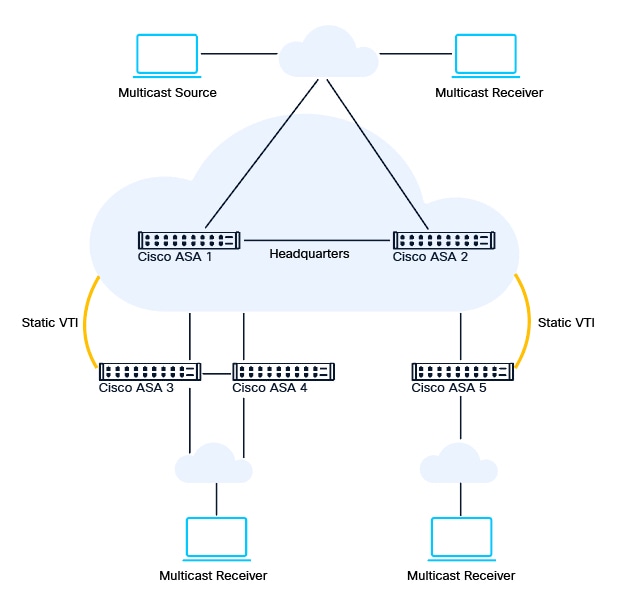
- ASA1 and ASA 2 are hubs in a high availability (HA) pair at the headquarters. ASA1 is the primary hub and ASA 2 is the secondary hub.
- ASA3 and ASA 4 are hubs in a high availability (HA) pair at the headquarters. ASA 3 is the primary hub and ASA 4 is the secondary hub.
- ASA 5 is a spoke at another branch office.
A network administrator wants to securely transmit real-time multicast application traffic from a multicast source to multicast receivers at the headquarters and branch offices. All sites use ASA Version 9.24.10.
The administrator configures OSPF and EIGRP as the underlay routing protocols for end-to-end reachability, and BGP as the overlay routing protocol. The administrator then deploys point-to-point VPN tunnels with SVTIs between the headquarters and branch office ASA devices, and configures multicast routing between the sites.
Scenario 1
RP is configured in ASA1 (FHR) and is mapped to the multicast group of the source IP address.
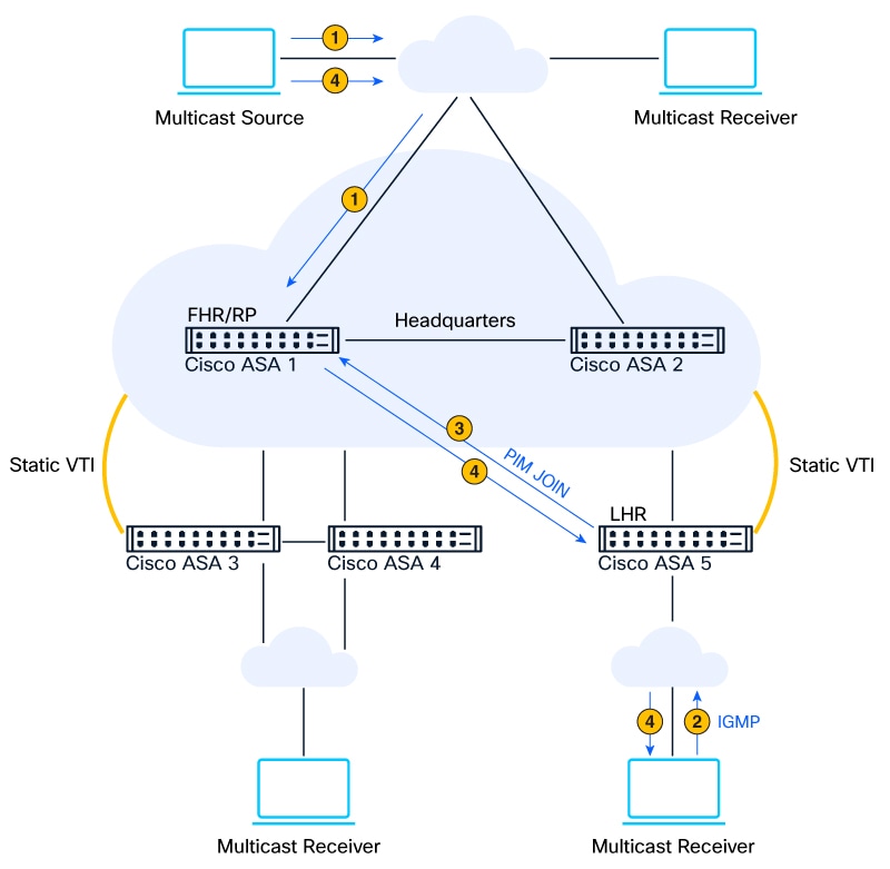
- Multicast traffic from the multicast source reaches the inside interface of ASA1.
- Multicast receiver sends IGMP messages to ASA3 to receive the multicast traffic.
- ASA3 sends PIM join messages towards the RP configured in ASA1.
- ASA1 forwards multicast traffic towards ASA3 to reach the multicast receiver.
Scenario 2
RP is configured in ASA3 (FHR) and is mapped to the multicast group of the source IP address.
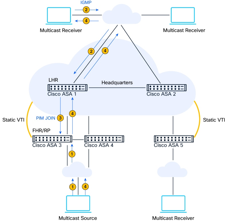
- Multicast traffic from the multicast source reaches the inside interface of ASA3.
- Multicast receiver sends IGMP messages to ASA1 to receive the multicast traffic.
- ASA1 sends PIM join messages towards the RP configured in ASA3.
- ASA3 forwards multicast traffic towards ASA1 to reach the multicast receiver.
Scenario 3
RP is configured in ASA5, which is the LHR and is mapped to the multicast group of the source IP address.
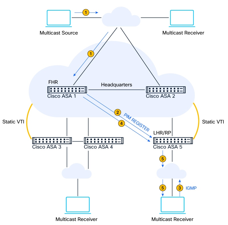
- Multicast traffic from the multicast source reaches the inside interface of ASA1.
- ASA1 sends a PIM register message to ASA5, which is the RP.
- Multicast receiver sends IGMP messages to ASA5 to receive the multicast traffic.
- ASA1 forwards the multicast traffic to the RP.
- ASA5 forwards the multicast traffic to the multicast receiver.
Prerequisites for multicast routing over SVTI tunnel
- ASA must be Version 9.24.10.
- ASA must have the Strong Encryption license.
- Enable unicast routing between the multicast source and the receivers.
- Configure basic routing to route traffic between the SVTI tunnels.
- Configure access control policies to permit traffic between the SVTI tunnels.
Guidelines for multicast routing over SVTI tunnel
We recommend some configurations for multicast routing over SVTI tunnel:
- Configure the FHR as the RP.
- Use a loopback interface as the RP IP address. However, you can use an SVTI IP address as an RP. Configure two loopback interfaces: one for the SVTI (IP unnumbered) and the other one for the PIM RP.
Ensure that you review these guidelines for multicast routing over VPN:
- For PIM-SM, ensure that you have configured an RP.
- Ensure that the RP is located near to the multicast source.
- For an external RP in a dynamic RP deployment, Bootstrap Router (BSR) is supported
- While existing PIM-SM sessions may survive an RP mismatch, new or restarted sessions will fail if the RP configuration is inconsistent. Verify that all devices in your multicast topology are configured with the same RP.
-
Configure the IGMP forward interface on the ingress interface of the LHR that points to the tunnel interface.
 Note
IGMP forwarding to tunnel interfaces is supported only on physical interfaces and subinterfaces.
Limitations for multicast routing over an SVTI tunnel
Protocol and addressing limitations
Review these protocol and addressing restrictions when implementing multicast routing over SVTI tunnels.
- IPv6 address in the overlay is not supported. An IPv6 address in the overlay is not supported. However, using an IPv6 address as the underlay in an SVTI tunnel with IPv4 multicast routing is supported.
- PIM Dense Mode (PIM-DM) is not supported.
- Multi-context mode is not supported
Interface, clustering, and failover limitations
Review these interface, clustering, and failover restrictions for multicast routing over IPsec tunnels.
- Multicast routing over IPsec tunnels with dynamic VTI (DVTI) is not supported.
- Multicast routing over IPsec tunnels with static VTI does not support clustering.
- RP failover with a global RP is not supported. If multiple RPs are configured, RP does not failover to global RP.
- When using static VTIs, backup multicast path failover through the underlay is not supported.
- Switchover events may result in transient packet loss.
Routing limitations
Review these routing limitations that affect multicast routing over SVTI tunnels.
- ECMP, traffic-zone multicast routing, multicast boundary filtering, and Bidirectional Forwarding Detection (BFD) over static VTI are not supported.
- A static mroute does not support SVTI as next-hop or outgoing interface.
- You cannot advertise an ASA device as a Candidate Rendezvous Point (C-RP).
- Dynamic SLA-based multipath and fallback are not supported. IPSLA-based failover is supported with static route.
Configure ASA interfaces
The hub and spokes are connected through a Nexus 9000 device.
ASA uses security levels from 0 to 100 for each interface to define how much the traffic from that network zone is trusted. Level 100 indicates highest trust, and Level 0 indicates lowest trust.
Configure the inside and outside interfaces in ASA. interface <interface_name> vlan <vlan_id> nameif <interface_name> ip-address <ip_address> <subnet_mask> NoteIf the interface is a switchport, convert it to a routed port using the no switchport command. Example:
|
Enable multicast routing on ASA devices
Before you begin
Ensure unicast routing is available between the multicast source and the receiver.Enable multicast routing. multicast-routing This command enables PIM-SM and IGMPv2 on the layer 3 ASA interface. The number of entries in the multicast routing tables are limited by the amount of RAM on the ASA. Example: |
Configure ASA as a static rendezvous point
Step 1 | Configure a loopback interface. interface loopback <number> Example: |
Step 2 | Configure a static RP address. pim rp-address ip_address [acl] (global RP) pim rp-address ip_address [acl] (ACL-based RP) The ip_address argument is the unicast IP address of the router assigned to be a PIM RP. Use the loopback IP address. The acl argument is the name or number of a standard ACL that defines with which multicast groups the RP should be used. Do not use a host ACL with this command. Example:In the example, 172.32.1.1 is the loopback IP address. |
Configure underlay routing for SVTI tunnel
In this deployment, for the end-to-end underlay routing:
- Hubs and spoke ASA3 use EIGRP
- Hubs and spoke ASA5 use OSPF
The hubs and spokes are inter-connected through a Cisco Nexus 9000.
Step 1 | Configure EIGRP on hubs and spoke ASA3. router eigrp <as_number> eigrp router-id <ip-address> network <ip-address> <subnet_mask>
| ||||||
Step 2 | Configure OSPF on hubs and spoke ASA5. router ospf <process-id> router-id <ip-address> network <ip-address> <subnet_mask> area <area_id> |
Configure VPN tunnels between hub and spokes
For secure transmission of the multicast traffic, you must configure point-to-point VPN tunnels between the hub and spokes.
Step 1 | Configure IKEv2 policy and its parameters. crypto ikev2 policy <policy_number> encryption [des | 3des | aes | aes-192 | aes-256 | aes-gcm | aes-gcm-192 | aes-gcm-256 | null] integrity{ md5 | sha-1 | sha-256 | sha-384 | sha-512 | null} group { { 1 | 2 | 5 | 14 | 19 | 20 | 21 | 24} prf { md5 | sha | sha256 | sha384 | sha512} lifetime seconds { <seconds>| none} |
Step 2 | Configure an IKEv2 proposal set that specifies the IPsec IKEv2 protocol, encryption, and integrity algorithms. crypto ipsec ikev2 ipsec-proposal <proposal_name> protocol esp{ encryptiondes | 3des | aes | aes-192 | aes-256 | aes-gcm | aes-gcm-192 | aes-gcm-256 | aes-gmac | aes-gmac-192 | aes-gmac-256 | null } | integrity{ md5 | sha-1 | sha-256 | sha-384 | sha-512 | null} protocol esp integrity{ md5 | sha-1 | sha-256 | sha-384 | sha-512 | null} |
Step 3 | Configure an IPsec profile. crypto ipsec profile <profile_name> set ikev2 ipsec-proposal <IPsec_proposal_name> set ikev2 local-identity key-id <key_ID> set reverse-route |
Step 4 | Configure a static virtual tunnel interface (SVTI) on the ASA. interface tunnel <tunnel_interface_number> nameif <interface_name> ip address <IP_address> <mask> tunnel source interface <interface_name> tunnel destination <IP_address> tunnel mode ipsec ipv4 tunnel protection ipsec profile <profile_name> |
Step 5 | Enable IKEv2 on the ASA SVTI. crypto ikev2 enable <svti_interface_name> |
|
ASA3 (Branch Office) |
ASA1/ASA2 (Headquarters) |
ASA1 (Branch Office) |
|---|---|---|
|
|
|
Configure overlay routing for SVTI tunnel
In this deployment, BGP provides overlay routing over the SVTI tunnel:
- Hubs, ASA1 and ASA2, are in BGP AS 100
- HA Spoke pair ASA3 and ASA4 are in BGP AS 300
- Spoke ASA5 is in BGP AS 200
Configure BGP on hubs and spokes. router bgp <as_number> address-family ipv4 unicast network <ip-address> remote-as <as_number> network <ip-address> activate For more information about configuring BGP in ASA, refer to Cisco Secure Firewall ASA Series General Operations CLI Configuration Guide, 9.24(x) |
|
ASA3 (Branch Office) |
Nexus 9000 |
ASA1 (Headquarters) |
|---|---|---|
|
|
|
Configure access lists
You must configure access lists on all the ASAs for permitting the incoming multicast traffic on the interfaces.
Step 1 | Configure a network object group. object-group network <group-name> network-object <subnet-address> <subnet-mask> Example: |
Step 2 | Configure an access control list to all interfaces globally. access-group <access_list_name>global access-list <access_list_name>extended permit ip object-group<source_group_name> <destination_ip_address> <destination_subnet_mask> Example: |
Verify multicast routing over an SVTI tunnel
You can use show commands to verify the multicast configurations for Scenario 1, Scenario 2, and Scenario 3 listed in the earlier topics.
-
show pim tunnel : Displays information about the PIM tunnel.
show pim tunnel output for Scenario 1
ASA3/ASA4 (Spoke)
ASA3/ASA4 (Hub)
ASA5 (Spoke)
show pim tunnel
Tunnel Name: PIM-Tunnel0
  Type: Encap
  RP: 172.32.1.1
  Source: 172.16.200.10
  State: UP
show pim tunnel Tunnel Name: PIM-Tunnel0 Type: Decap RP: 172.32.1.1* Source: - State: UPshow pim tunnel Tunnel Name: PIM-Tunnel0 Type: Encap RP: 172.32.1.1 Source: 17.17.1.2 State: UPshow pim tunnel output for Scenario 2ASA3/ASA4 (Spoke)
ASA3/ASA4 (Hub)
ASA5 (Spoke)
show pim tunnel
Tunnel Name: PIM-Tunnel0
  Type: Decap
  RP: 172.32.1.2*
  Source: -
  State: UP
show pim tunnel Tunnel Name: PIM-Tunnel0 Type: Encap RP: 172.32.1.2 Source: 172.16.200.11 State: UPshow pim tunnel Tunnel Name: PIM-Tunnel0 Type: Encap RP: 172.32.1.2 Source: 17.17.1.2 State: UPshow pim tunnel output for Scenario 3ASA3/ASA4 (Hub)
ASA5 (Spoke)
show pim tunnel
Tunnel Name: PIM-Tunnel0
  Type: Encap
  RP: 172.32.1.3
  Source: 17.17.1.4
  State: UP
show pim tunnel Tunnel Name: PIM-Tunnel0 Type: Decap RP: 172.32.1.3* Source: - State: UP -
show mroute : Displays the IPv4 multicast routing table to verify multicast traffic forwarding.
In this deployment, the SFT and SJT flags are set. If these flags are set, the end to end multicast traffic is getting forwarded.show mroute output for Scenario 1ASA3/ASA4 (Branch Office)
ASA3/ASA4 (Headquarters)
ASA5 (Branch Office)
show mroute 235.0.0.1
Multicast Routing Table
Flags: D - Dense, S - Sparse, B - Bidir Group, s - SSM Group, C - Connected, L - Local, I - Received Source Specific Host Report,P - Pruned, R - RP-bit set, F - Register flag, T - SPT-bit set,J - Join SPT
Timers: Uptime/Expires
Interface state: Interface, State

(*, 235.0.0.1), 1w1d/never, RP 172.32.1.1, flags: SCJ
 Incoming interface: tun200
 RPF nbr: 172.16.200.11
 Immediate Outgoing interface list:
 700, Forward, 1w1d/never

(192.168.100.10, 235.0.0.1), 1w1d/00:03:28, flags: SJT
 Incoming interface: tun200
 RPF nbr: 172.16.200.11
 Inherited Outgoing interface list:
 700, Forward, 1w1d/never
show mroute 235.0.0.1 Multicast Routing Table Flags: D - Dense, S - Sparse, B - Bidir Group, s - SSM Group, C - Connected, L - Local, I - Received Source Specific Host Report, P - Pruned, R - RP-bit set, F - Register flag, T - SPT-bit set, J - Join SPT Timers: Uptime/Expires Interface state: Interface, State *, 235.0.0.1), 1w1d/00:03:22, RP 172.32.1.1, flags: S Incoming interface: PIM-Tunnel0 RPF nbr: 172.32.1.1 Immediate Outgoing interface list: tun200, Forward, 1w1d/00:02:50 tun100, Forward, 1w1d/00:03:22 (192.168.100.10, 235.0.0.1), 1w1d/00:03:28, flags: SFT Incoming interface: 600 RPF nbr: 192.168.100.10 Immediate Outgoing interface list: tun100, Forward, 1w1d/00:03:22 tun200, Forward, 1w1d/00:02:50show mroute 235.0.0.1 Multicast Routing Table Flags: D - Dense, S - Sparse, B - Bidir Group, s - SSM Group, C - Connected, L - Local, I - Received Source Specific Host Report, P - Pruned, R - RP-bit set, F - Register flag, T - SPT-bit set,J - Join SPT Timers: Uptime/Expires Interface state: Interface, State (*, 235.0.0.1), 1w1d/never, RP 172.32.1.1, flags: SCJ Incoming interface: tun100 RPF nbr: 17.17.1.4 Immediate Outgoing interface list: 500, Forward, 1w1d/never (192.168.100.10, 235.0.0.1), 1w1d/00:03:28, flags: SJT Incoming interface: tun100 RPF nbr: 17.17.1.4 Inherited Outgoing interface list: 500, Forward, 1w1d/never- In the headquarter device, the SFT flag is set as it is the source.
- In the branch office device, the SJT flag is set as they are the receivers.
show mroute output for Scenario 2ASA3/ASA4 (Branch Office)
ASA3/ASA4 (Headquarters)
ASA5 (Branch Office)
show mroute 228.0.0.1
Multicast Routing Table
Flags: D - Dense, S - Sparse, B - Bidir Group, s - SSM Group,
       C - Connected, L - Local, I - Received Source Specific Host Report,P - Pruned, R - RP-bit set, F - Register flag, T - SPT-bit set,J - Join SPT
Timers: Uptime/Expires Interface state: Interface, State

(*, 228.0.0.1), 1w1d/never, RP 172.32.1.2, flags: SCJ
  Incoming interface: PIM-Tunnel0
  RPF nbr: 172.32.1.2
  Immediate Outgoing interface list:
    700, Forward, 1w1d/never

(192.168.0.10, 228.0.0.1), 00:07:41/00:03:29, flags: SJT
  Incoming interface: tun200
  RPF nbr: 172.16.200.11
  Inherited Outgoing interface list:
    700, Forward, 1w1d/never
show mroute 228.0.0.1 Multicast Routing Table Flags: D - Dense, S - Sparse, B - Bidir Group, s - SSM Group, C - Connected, L - Local, I - Received Source Specific Host Report, P - Pruned, R - RP-bit set, F - Register flag, T - SPT-bit set,J - Join SPT Timers: Uptime/Expires Interface state: Interface, State (192.168.0.10, 228.0.0.1), 00:08:52/00:03:29, flags: ST Incoming interface: tun100 RPF nbr: 17.17.1.2 Immediate Outgoing interface list: tun200, Forward, 00:08:52/00:02:36show mroute 228.0.0.1 Multicast Routing Table Flags: D - Dense, S - Sparse, B - Bidir Group, s - SSM Group, C - Connected, L - Local, I - Received Source Specific Host Report, P - Pruned, R - RP-bit set, F - Register flag, T - SPT-bit set,J - Join SPT Timers: Uptime/Expires Interface state: Interface, State (192.168.0.10, 228.0.0.1), 00:08:44/00:03:29, flags: SFT Incoming interface: 500 RPF nbr: 192.168.0.10 Immediate Outgoing interface list: tun100, Forward, 00:06:55/00:02:36show mroute output for Scenario 3ASA3/ASA4 (Headquarters)
ASA5 (Branch Office)
show mroute 235.0.0.1
Multicast Routing Table
Flags: D - Dense, S - Sparse, B - Bidir Group, s - SSM Group,
 C - Connected, L - Local, I - Received Source Specific Host Report,
 P - Pruned, R - RP-bit set, F - Register flag, T - SPT-bit set,J - Join SPT
Timers: Uptime/Expires Interface state: Interface, State
(192.168.100.10, 235.0.0.1), 00:06:18/00:03:28, flags: SFT
 Incoming interface: 600
 RPF nbr: 192.168.100.10
 Immediate Outgoing interface list:
 tun100, Forward, 00:04:16/00:03:17
show mroute 235.0.0.1 Multicast Routing Table Flags: D - Dense, S - Sparse, B - Bidir Group, s - SSM Group, C - Connected, L - Local, I - Received Source Specific Host Report, P - Pruned, R - RP-bit set, F - Register flag, T - SPT-bit set,J - Join SPT Timers: Uptime/Expires nterface state: Interface, State (*, 235.0.0.1), 00:21:03/never, RP 172.32.1.3, flags: SCJ Incoming interface: PIM-Tunnel0 RPF nbr: 172.32.1.3 Immediate Outgoing interface list: 500, Forward, 00:21:03/never (192.168.100.10, 235.0.0.1), 00:04:24/00:03:29, flags: SJT Incoming interface: tun100 RPF nbr: 17.17.1.4 Inherited Outgoing interface list: 500, Forward, 00:21:03/never
Troubleshoot multicast routing over an SVTI tunnel
Provides troubleshooting guidance for multicast routing issues over SVTI tunnels in Secure Firewall environments, including symptoms, causes, and resolution steps.
Troubleshoot multicast traffic issues
-
Symptoms:
- Unicast connectivity across VTI tunnel works fine.
- Multicast stream never starts even when the receiver device sends an IGMP join.
- LHR does not receive multicast traffic even though the source device is active.
- Perform a ping between tunnel endpoints to ensure basic connectivity and if SVTI is up.
- Run show pim interface to verify if PIM is enabled in the SVTI.
- Run show pim neighbor to ensure PIM adjacency is established across the tunnel.
- Run show mroute to verify the incoming and outgoing interfaces.
- Run show route <source-ip> to ensure that the RPF path points to the VTI.
Use clear commands
- clear pim topology and clear igmp group: Resets the multicast state for any recovery.
- clear mroute <multicast_ipaddress>: Clears entries for a specific multicast group.
Use debug commands
NoteUse debug commands only during low network traffic periods and for specific troubleshooting or TAC sessions, as they increase CPU usage.
- debug pim: Debugs PIM configuration and events.
- debug igmp: Debugs IGMP configuration and events.
- debug mfib: Debugs MFIB configuration and events.