Hardware features
|
Feature |
C8570-G2 |
C8550-G2 |
|---|---|---|
|
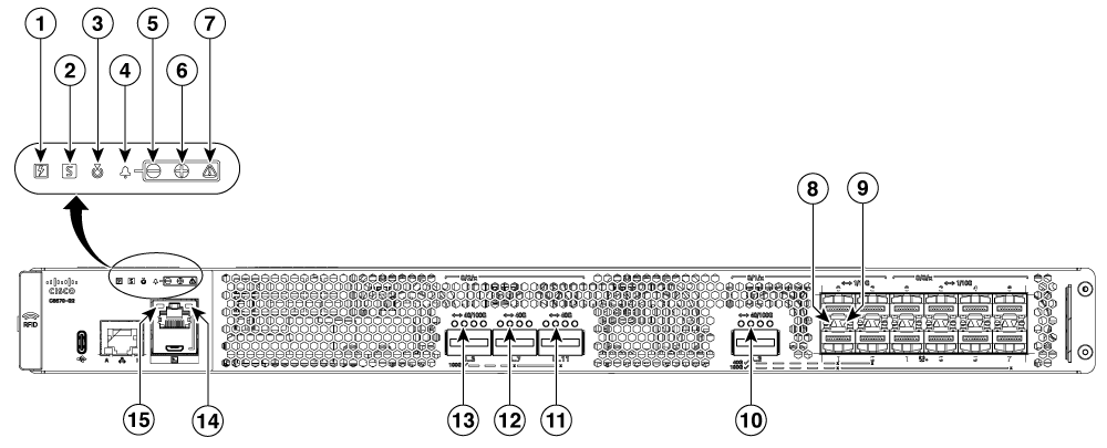
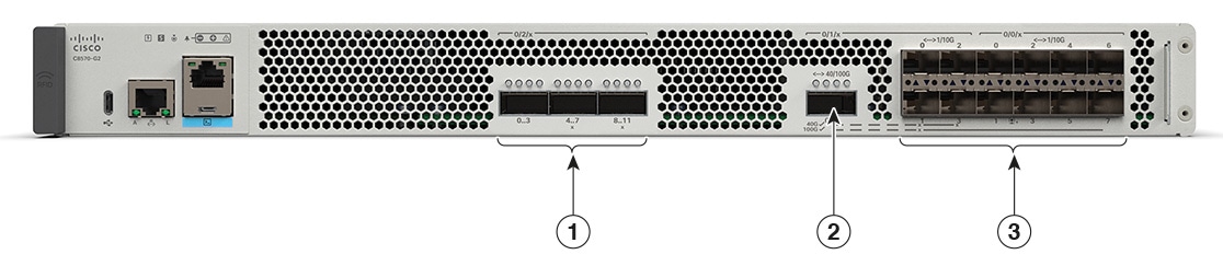
Ethernet Ports |
12x SFP+ 2x QSFP28 100/40GE 2x QSFP 40GE |
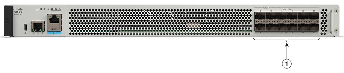
12x SFP+ |
|
Rack Units |
One |
One |
|
System Memory (DRAM) |
32 GB default (two DIMMS) can be upgraded to 64 GB total |
32 GB default (two DIMMS) can be upgraded to 64 GB total |
|
Storage |
480 GB SSD |
480 GB SSD |
|
Management Interface |
RJ-45 console port |
RJ-45 console port |
|
Console Port |
1xRJ45, 1x USB Micro-USB |
1xRJ45, 1x USB Micro-USB |
|
USB Ports |
USB Type C |
USB Type C |
|
Rack Installation |
Two post and four post |
Two post and four post |
|
Feature |
C8570-G2 | C8550-G2 |
|---|---|---|
|
Supported Transceivers |
12x SFP+,2x QSFP28 100/40GE, 2x QSFP 40GE 1G SFP or 10G SFP+ can be configured with dual-rate 10GE ports as follows: 10G SFP+ on dual-rate 10GE Interface: Auto-negotiation protocol is not supported, and automatic negotiation cannot be configured using negotiation auto command. 1G SFP on dual-rate 10GE Interface: Auto-negotiation protocol is supported, and automatic negotiation can be configured using negotiation auto command. To disable auto negotiation, use no negotiation auto command. |
12x SFP+ 1G SFP or 10G SFP+ can be configured with dual-rate 10GE ports as follows: 10G SFP+ on dual-rate 10GE Interface: Auto-negotiation protocol is not supported, and automatic negotiation cannot be configured using negotiation auto command. 1G SFP on dual-rate 10GE Interface: Auto-negotiation protocol is supported, and automatic negotiation can be configured using negotiation auto command. To disable auto negotiation, use no negotiation auto command. |
|
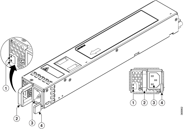
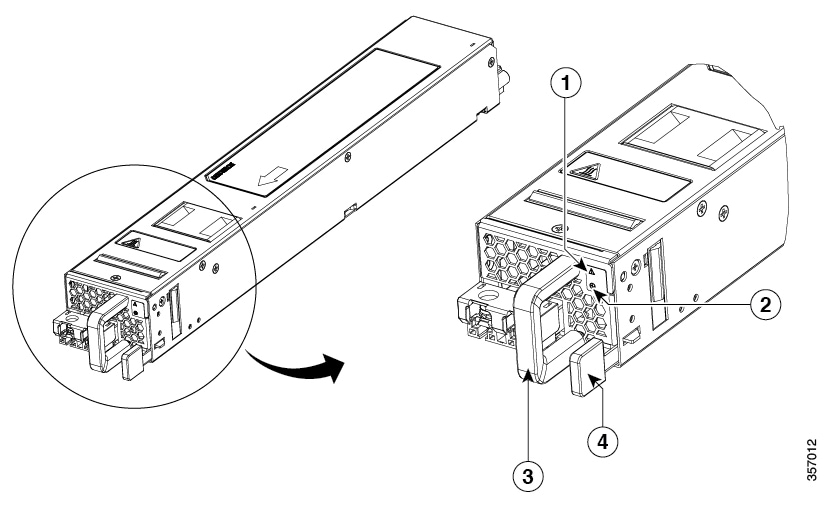
Power Supplies |
C8570-G2 | C8550-G2 |
|---|---|---|
|
AC |
PWR-CH1-750WACR |
PWR-CH1-750WACR |
|
DC |
PWR-CH1-950WDCR |
PWR-CH1-950WDCR |


 Feedback