
Network Segmentation
Feature history of segmentation
|
Feature Name |
Release Information |
Description |
|---|---|---|
|
Added Support for 2,000 VRFs |
Cisco IOS XE Catalyst SD-WAN Release 17.13.1a Cisco Catalyst SD-WAN Control Components Release 20.13.1 |
Increased support from 300 VRFs to 2,000 VRFs in the overlay network, with up to 500 for a single device. |
Network segments in Cisco Catalyst SD-WAN
A network segment is a feature that
- exists within VRFs that divide the overlay network into separate segments
- is identified in packets by a segment identifier and an associated label, and
- provides Layer 3 isolation with prefixes kept in a separate route table.
Segment identifiers and route tables
In the Cisco Catalyst SD-WAN overlay network, VRFs divide the network into different segments.
Cisco Catalyst SD-WAN employs the more prevalent and scalable model of creating segments. Essentially, segmentation is done at the edges of a router, and the segmentation information is carried in the packets in the form of an identifier.
The figure shows the propagation of routing information inside a VRF.
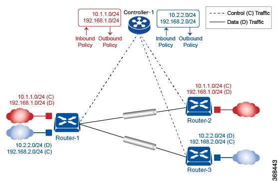
In this figure:
-
Router-1 subscribes to two VRFs, red and blue.
- The red VRF caters to the prefix 10.1.1.0/24 (either directly through a connected interface or learned using the IGP or BGP).
- The blue VRF caters to the prefix 10.2.2.0/24 (either directly through a connected interface or learned using the IGP or BGP).
-
Router-2 subscribes to the red VRF.
- This VRF caters to the prefix 192.168.1.0/24 (either directly through a connected interface or learned using the IGP or BGP).
-
Router-3 subscribes to the blue VRF.
- This VRF caters to the prefix 192.168.2.0/24 (either directly through a connected interface or learned using the IGP or BGP).
Because each router has an Overlay Management Protocol (OMP) connection over a TLS tunnel to a Cisco SD-WAN Controller, it propagates its routing information to the Cisco SD-WAN Controller. On the Cisco SD-WAN Controller, the network administrator can enforce policies to drop routes, to change TLOCs, which are overlay next hops, for traffic engineering or service chaining. A network administrator can apply these policies as inbound and outbound policies on the Cisco SD-WAN Controller.
All the prefixes belonging to a single VRF are kept in a separate route table. This provides the Layer 3 isolation required for the various segments in the network. So, Router-1 has two VRF route tables, and Router-2 and Router-3 each have one route table. In addition, the Cisco SD-WAN Controller maintains the VRF context of each prefix.
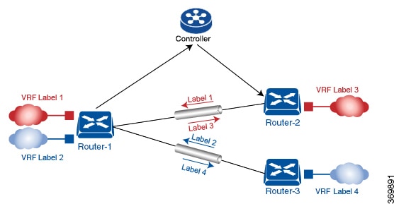
Separate route tables provide isolation on a single node. So how is routing information propagated across the network?
In the Cisco Catalyst SD-WAN solution, this is done using VRF identifiers, as shown in the figure. AVRF ID, which is carried in a packet, identifies each VRF on a link. When you configure a VRF on a router, the VRF has a label associated with it. The router sends the label, along with the VRF ID, to the Cisco SD-WAN Controller. The Cisco SD-WAN Controller propagates this router-to-VRF ID mapping information to the other routers in the domain. The remote routers then use this label to send traffic to the appropriate VRF. The local routers, on receiving the data with the VRF ID label, use the label to demultiplex the data traffic. This is similar to how MPLS labels are used. This design is based on standard RFCs and is compliant with regulatory procedures such as PCI and HIPAA.
 Note
NoteThe transport network that connects the routers is completely unaware of the VRFs. Only the routers know about VRFs; the rest of the network follows standard IP routing.
VRFs used in Cisco Catalyst SD-WAN segmentation
A VRF is a mechanism that
- separates traffic in the Cisco Catalyst SD-WAN solution
- keeps transport interfaces (TLOCs) in the global VRF and defines each TLOC by IP address, color, and encapsulation, which the OMP session advertises to Cisco SD-WAN Controllers
- provides a management VRF that carries out-of-band network management traffic and is configured and enabled by default.
Global VRF
The global VRF is used for transport. To enforce the inherent separation between services (such as prefixes that belong to the enterprise) and transport (the network that connects the routers), all the transport interfaces, that is, all the TLOCs, are kept in the global VRF. This ensures that the transport network cannot reach the service network by default. Multiple transport interfaces can belong to the same VRF, and packets can be forwarded to and from transport interfaces.
A global VRF contains all the interfaces for a device, except the management interface, and all the interfaces are disabled. For the control plane to establish itself so that the overlay network can function, you must configure tunnel interfaces in a global VRF. For each interface in a global VRF, you must set an IP address, and create a tunnel connection that sets the color and encapsulation for the WAN transport connection. (The encapsulation is used for the transmission of data traffic.) These three parameters—IP address, color, and encapsulation—define a TLOC (transport location) on the router. The OMP session running on each tunnel sends the TLOC to the Cisco SD-WAN Controllers so that they can learn the overlay network topology.
Dual-stack support on transport VPNs
In the global VRF, Cisco IOS XE Catalyst SD-WAN devices and Cisco SD-WAN Controller support dual stack. To enable dual stack, configure an IPv4 address and an IPv6 address on the tunnel interface. The router learns from a Cisco SD-WAN Controller whether a destination supports IPv4 or IPv6 addresses. When forwarding traffic, a router chooses either the IPv4 or the IPv6 TLOC, based on the destination address. But IPv4 is always preferred when configured.
Management VRF
Mgmt-Intf is the management VRF on Cisco IOS XE Catalyst SD-WAN devices. It is configured and enabled by default. It carries out-of-band network management traffic among the devices in the overlay network. You can modify this configuration, if required.
Restrictions for segmentation
One inherent limitation of segmentation is its scope. Segmentation solutions either are complex or are limited to a single device or pair of devices connected using an interface.
- Ability to group prefixes into a unique route table (RIB or FIB).
- Ability to associate an interface with a route table so that traffic traversing the interface is routed based on prefixes in that route table.
To extend the functionality throughout the network, the segmentation information needs to be carried to the relevant points in the network.
Use cases for segmentation
- An enterprise wants to keep different lines of business separate (for example, for security or audit reasons).
- The IT department wants to keep authenticated users separate from guest users.
- A retail store wants to separate video surveillance traffic from transactional traffic.
- An enterprise wants to give business partners selective access only to some portions of the network.
- A service or business needs to enforce regulatory compliance, such as compliance with HIPAA, the U.S. Health Insurance Portability and Accountability Act, or with the Payment Card Industry (PCI) security standards.
- A service provider wants to provide VPN services to its medium-sized enterprises.
Enable network-wide segmentation
There are two approaches to providing this network-wide segmentation:
- Define the grouping policy at every device and on every link in the network (basically, you perform Steps 1 and 2 on every device).
- Define the grouping policy at the edges of the segment, and then carry the segmentation information in the packets for intermediate nodes to handle.
The first approach is useful if every device is an entry or exit point for the segment, which is generally not the case in medium and large networks. The second approach is much more scalable and keeps the transport network free of segments and complexity.
Configure VRF with Cisco SD-WAN Manager templates
In Cisco SD-WAN Manager, use a CLI template to configure VRFs for a device. For each VRF, configure a subinterface and link the subinterface to the VRF. You can configure up to 300 VRFs.
Starting from Cisco IOS XE Catalyst SD-WAN Release 17.13.1a, you can configure up to 2,000 VRFs in the overlay network and up to 500 VRFs for a single device. Each VRF deals with fewer routes than before, making the distribution of routes across the network more efficient and easier to scale.
When you push a CLI template to a device, Cisco SD-WAN Manager overwrites existing configuration on the device and loads the configuration defined in the CLI template. Consequently, the template cannot only provide the new content being configured, such as VRFs. The CLI template must include all the configuration details required by the device. To display the relevant configuration details on a device, use the show sdwan running-config command.
These devices are supported:
- Cisco ASR1001-HX
- ASR1002-HX
- C8500-12X
- C8500-12X4QC
- C8500L-8S4X
- C8500-20X6C
Configure VPNs Using Cisco SD-WAN Manager Templates
Create a VPN template
Cisco IOS XE Catalyst SD-WAN devices use VRFs for segmentation and network isolation. However, these steps still apply if you are configuring segmentation for Cisco IOS XE Catalyst SD-WAN devices through Cisco SD-WAN Manager. When you complete the configuration, the system automatically converts the VPNs to VRFs for Cisco IOS XE Catalyst SD-WAN devices.
NoteYou can configure a static route through the VPN template.
Step 1 | From the Cisco SD-WAN Manager menu, choose . |
Step 2 | Click Device Templates, and click Create Template. NoteIn Cisco vManage Release 20.7.x and earlier releases Device Templates is called Device. |
Step 3 | From the Create Template drop-down list, choose From Feature Template. |
Step 4 | From the Device Model drop-down list, choose the type of device for which you wish to create the template. |
Step 5 | To create a template for VPN 0 or VPN 512:
|
Step 6 | Create a template for VPNs. Range: 1 to 65525, excluding 512. For details see the VRF range behavior change described here.
|
Step 7 | In Template Name, enter a name for the template. The name can be up to 128 characters and can contain only alphanumeric characters. |
Step 8 | In Template Description, enter a description of the template. The description can be up to 2048 characters and can contain only alphanumeric characters. |
Configure basic VPN parameters
Step 1 | Choose Basic Configuration and configure VPN parameters. Parameters marked with an asterisk are required to configure a VPN.
NoteTo complete the configuration of the transport VPN on a router, you must configure at least one interface in VPN 0. | ||||||||
Step 2 | Click Save. |
Configure basic interface functionality
Configure basic interface functionality in a VPN by choosing Basic Configuration and setting required parameters, or by using CLI commands on supported devices, to define addressing, administrative state, helper addresses, and bandwidth notification thresholds.
Parameters marked with an asterisk are required to configure an interface. You can enable or disable the interface, define the interface name and description, choose IPv4 or IPv6, set dynamic or static addressing, add secondary addresses, configure DHCP helper addresses, and set bandwidth notifications.
Step 1 | Choose Basic Configuration and configure interface parameters. NoteParameters marked with an asterisk are required to configure an interface.
| ||||||||||||||||||||||||||||||||||||||||||||||||||||||||
Step 2 | Click Save to save the feature template. | ||||||||||||||||||||||||||||||||||||||||||||||||||||||||
Create a tunnel interface
On Cisco IOS XE Catalyst SD-WAN devices, you can configure up to eight tunnel interfaces. This means that each Cisco IOS XE Catalyst SD-WAN device router can have up to eight TLOCs. On Cisco Catalyst SD-WAN Controllers and Cisco SD-WAN Manager, you can configure one tunnel interface.
For the control plane to establish itself so that the overlay network can function, you must configure WAN transport interfaces in VPN 0. The WAN interface enables the flow of tunnel traffic to the overlay. You can add other parameters only after you configure the WAN interface as a tunnel interface.
To configure a tunnel interface, select Interface Tunnel and configure these parameters:
| Parameter Name | Description |
|---|---|
| Tunnel Interface | Click On to create a tunnel interface. |
| Color | Select a color for the TLOC. |
|
Color Description |
Minimum supported release: Cisco Catalyst SD-WAN Manager Release 20.18.1 Enter a description associated to the TLOC color. |
|
Full Port Hop |
Minimum release: Cisco IOS XE Catalyst SD-WAN Release 17.18.1a Enable full port hopping at the TLOC level to allow devices to establish connections with controllers by switching to the next port if the current port is blocked or non-functional. Default: Disabled |
| Port Hop | Click On to enable port hopping, or click Off to disable it. If port hopping is enabled globally, you can disable it on an individual TLOC (tunnel interface). To control port hopping on a global level, use the System configuration template. Default: Enabled Cisco SD-WAN Manager and Cisco Catalyst SD-WAN Controller default: Disabled Starting from Cisco IOS XE Catalyst SD-WAN Release 17.18.1a, this field is deprecated. Instead use the Full Port Hop option. See the Full Port Hop field. |
|
TCP MSS |
TCP MSS affects any packet that contains an initial TCP header that flows through the router. When configured, TCP MSS is examined against the MSS exchanged in the three-way handshake. The MSS in the header is lowered if the configured TCP MSS setting is lower than the MSS in the header. If the MSS header value is already lower than the TCP MSS, the packets flow through unmodified. The host at the end of the tunnel uses the lower setting of the two hosts. If the TCP MSS is to be configured, it should be set at 40 bytes lower than the minimum path MTU. Specify the MSS of TPC SYN packets passing through the . By default, the MSS is dynamically adjusted based on the interface or tunnel MTU such that TCP SYN packets are never fragmented. Range: 552 to 1460 bytes Default: None |
|
Clear-Dont-Fragment |
Configure Clear-Dont-Fragment for packets that arrive at an interface that has Don't Fragment configured. If these packets are larger than what MTU allows, they are dropped. If you clear the Don't Fragment bit, the packets are fragmented and sent. Click On to clear the Dont Fragment bit in the IPv4 packet header for packets being transmitted out of the interface. When the Dont Fragment bit is cleared, packets larger than the MTU of the interface are fragmented before being sent. NoteClear-Dont-Fragment clears the Dont Fragment bit and the Dont Fragment bit is set. For packets not requiring fragmentation, the Dont Fragment bit is not affected. |
| Allow Service | Select On or Off for each service to allow or disallow the service on the interface. |
To configure additional tunnel interface parameters, click Advanced Options:
| Parameter Name | Description |
|---|---|
| Carrier |
Select the carrier name or private network identifier to associate with the tunnel. Values: carrier1, carrier2, carrier3, carrier4, carrier5, carrier6, carrier7, carrier8, default Default: default |
| NAT Refresh Interval | Enter the interval between NAT refresh packets sent on a DTLS or TLS WAN transport connection. Range: 1 through 60 seconds Default: 5 seconds |
| Hello Interval |
Enter the interval between Hello packets sent on a DTLS or TLS WAN transport connection. Range: 100 through 10000 milliseconds Default: 1000 milliseconds (1 second) |
| Hello Tolerance |
Enter the time to wait for a Hello packet on a DTLS or TLS WAN transport connection before declaring that transport tunnel to be down. Range: 12 through 60 seconds Default: 12 seconds |
Configure DNS and static hostname mapping
Step 1 | Click DNS, and configure DNS and static hostname mapping parameters. Configure these parameters:
| ||||||||||||||||||
Step 2 | Click Save to save the feature template. | ||||||||||||||||||
Configure Segmentation Using the CLI
Configure VRFs using the CLI commands
To segment user networks and user data traffic locally at each site and to interconnect user sites across the overlay network, you create VRFs on Cisco IOS XE Catalyst SD-WAN devices. To enable the flow of data traffic, you associate interfaces with each VRF, assigning an IP address to each interface. These interfaces connect to local-site networks, not to WAN transport clouds. For each of these VRFs, you can set other interface-specific properties, and you can configure features specific for the user segment, such as BGP and OSPF routing, VRRP, QoS, traffic shaping, and policing.
On Cisco IOS XE Catalyst SD-WAN devices, a global VRF is used for transport. All Cisco IOS XE Catalyst SD-WAN devices have Mgmt-intf as the default management VRF.
Note- Use the config-transaction command to open CLI configuration mode. The config terminal command is not supported on Cisco IOS XE Catalyst SD-WAN devices.
- VRF ID Range: 1 to 65525, excluding 512. For details see the VRF range behavior change described here.
Step 1 | Configure service VRFs. Example: |
Step 2 | Configure the tunnel interface to be used for overlay connectivity. Example:Each tunnel interface binds to a single WAN interface. For example, if the router interface is Gig0/0/2, the tunnel interface number is 2. |
Step 3 | If the router is not connected to a DHCP server, configure the IP address of the WAN interface. Example: |
Step 4 | Configure tunnel parameters. Example:If an IP address is manually configured on the router, configure a default route as shown. The IP address below indicates a next-hop IP address. |
Step 5 | Enable OMP to advertise VRF segment vroutes. Example: |
Step 6 | Configure the service VRF interface. Example: |
What to do next
Run the show ip vrf brief command to view information about the VRF interface.
Device# sh ip vrf brief
  Name                             Default RD            Interfaces
  10                               1:10                  Gi4
  11                               1:11                  Gi3
  30                               1:30
  65528                            <not set>             Lo65528
Configure network segmentation with VRFs
Also, you generally create a centralized control policy that controls how the VPN traffic is propagated through the rest of the network. In this particular example, we create a central policy, shown below, to drop unwanted prefixes from propagating through the rest of the network. You can use a single Cisco Catalyst SD-WAN Controller policy to enforce policies throughout the network.
Step 1 | Create a list of site IDs for sites where you want to drop unwanted prefixes Example: |
Step 2 | Create a prefix list for prefixes that you do not want to propagate Example: |
Step 3 | Create the control policy Example: |
Step 4 | Apply the policy to prefixes inbound to the Cisco Catalyst SD-WAN Controller controller Example: |
Here is the full policy configuration on the Cisco Catalyst SD-WAN Controller controller:
apply-policy
 site-list 20-30
  control-policy drop-unwanted-routes in
 !
!
policy
 lists
  site-list 20-30
   site-id 20
   site-id 30
  !
  prefix-list drop-list
   ip-prefix 10.200.1.0/24
  !
 !
 control-policy drop-unwanted-routes
  sequence 10
   match route
    prefix-list drop-list
   !
   action reject
   !
  !
  default-action accept
 !
!
Segmentation CLI Reference
Documents CLI commands for monitoring and configuring segmentation on vEdge routers and VRFs.
CLI commands for monitoring segmentation (VRFs).
- show dhcp
- show ipv6 dhcp
- show ip vrf brief
- show igmp commands
- show ip igmp groups
- show pim commands