
High Availability
High Availability
Feature history of high availability
Feature history
|
Feature name |
Release information |
Description |
|---|---|---|
|
Controller Group Redundancy Management |
Cisco IOS XE Catalyst SD-WAN Release 17.18.1a Cisco Catalyst SD-WAN Manager Release 20.18.1 |
Cisco IOS XE Catalyst SD-WAN devices ensure consistent connectivity by connecting to SD-WAN Controllers specified in their Control Group list. They maintain redundancy by switching to alternate SD-WAN Controllers within or across groups if the primary controllers become unavailable. |
High availability
A high availability solution is a feature that
- ensures network services remain resilient to failure
- provides continuous access to network resources by addressing potential causes of downtime, and
- combines hardware redundancy, robust network design, and software mechanisms.
High availability details
The goal of any high availability solution is to ensure that all network services are resilient to failure. Such a solution aims to provide continuous access to network resources by addressing the potential causes of downtime through functionality, design, and best practices. The core of the Cisco Catalyst SD-WAN high availability solution is achieved through a combination of three factors:
- Functional hardware device redundancy. The basic strategy consists of installing and provisioning redundant hardware devices and redundant components on the hardware. These devices are connected by a secure control plane mesh of Datagram Transport Layer Security (DTLS) connections among themselves, which allows for rapid failover should a device fail or otherwise become unavailable. A key feature of the Cisco Catalyst SD-WAN control plane is that it is established and maintained automatically, by the Cisco IOS XE Catalyst SD-WAN devices and software themselves.
- Robust network design.
- Software mechanisms ensure rapid recovery from a failure. To provide a resilient control plane, the Cisco Catalyst SD-WAN Overlay Management Protocol (OMP) regularly monitors the status of all Cisco IOS XE Catalyst SD-WAN devices in the network and automatically adjusts to changes in the topology as devices join and leave the network. For data plane resiliency, the Cisco Catalyst SD-WAN software implements standard protocol mechanisms, specifically Bidirectional Forwarding Detection (BFD), which runs on the secure IPsec tunnels between routers.
Recovery from a failure is a function of the time it takes to detect the failure and then repair or recover from it. The Cisco Catalyst SD-WAN solution provides the ability to control the amount of time to detect a failure in the network. In most cases, repair of the failure is fairly instantaneous.
A standard best practice in any network setup is to install redundant hardware at all levels, including duplicate parallel routers and other systems, redundant fans, power supplies and other hardware components within these devices, and backup network connections. Providing high availability in the Cisco Catalyst SD-WAN solution is no different. A network design that is resilient in the face of hardware failure should include redundant Cisco SD-WAN Validators, Cisco SD-WAN Controllers, and routers and any available redundant hardware components.
Recovery from the total failure of a hardware component in the Cisco Catalyst SD-WAN overlay network happens in basically the same way as in any other network. A backup component has been preconfigured, and it is able to perform all necessary functions by itself.
In addition to simple duplication of hardware components, the high availability of a Cisco Catalyst SD-WAN network can be enhanced by following best practices to design a network that is robust in the face of failure. In one such network design, redundant components are spread around the network as much as possible. Design practices include situating redundant Cisco SD-WAN Validators and Cisco SD-WAN Controllers at dispersed geographical locations and connecting them to different transport networks. Similarly, the routers at a local site can connect to different transport networks and can reach these networks through different NATs and DMZs.
The Cisco Catalyst SD-WAN software support for high availability and resiliency in the face of failure is provided both in the control plane, using the standard DTLS protocol and the proprietary Cisco Catalyst SD-WAN Overlay Management Protocol (OMP), and in the data plane, using the industry-standard protocols BFD, BGP, OSPF, and VRRP.
The Cisco Catalyst SD-WAN control plane operates in conjunction with redundant components to ensure that the overlay network remains resilient if one of the components fails. The control plane is built on top of DTLS or TLS connections between the Cisco devices, and it is monitored by the Cisco Catalyst SD-WAN OMP protocol, which establishes peering sessions (similar to BGP peering sessions) between pairs of Cisco SD-WAN Controllers and routers, and between pairs of Cisco SD-WAN Controllers. These peering sessions allow OMP to monitor the status of the Cisco devices and to share the information among them so that each device in the network has a consistent view of the overlay network. The exchange of control plane information over OMP peering sessions is a key piece in the Cisco Catalyst SD-WAN high availability solution:
- Cisco SD-WAN Controllers quickly and automatically learn when a Cisco SD-WAN Validator or a router joins or leaves the network. They can then rapidly make the necessary modifications in the route information that they send to the routers.
- Cisco SD-WAN Validator quickly and automatically learn when a device joins the network and when a Cisco SD-WAN Controller controller leaves the network. They can then rapidly make the necessary changes to the list of Cisco SD-WAN Controller IP addresses that they send to routers joining the network.
- Cisco SD-WAN Validators learn when a domain has multiple Cisco SD-WAN Controllers and can then provide multiple Cisco SD-WAN Controller addresses to routers joining the network.
- Cisco SD-WAN Controllers learn about the presence of other Cisco SD-WAN Controllers, and they all automatically synchronize their route tables. If one Cisco SD-WAN Controller fails, the remaining systems take over management of the control plane, simply and automatically, and all routers in the network continue to receive current, consistent routing and TLOC updates from the remaining Cisco SD-WAN Controllers.
A highly available Cisco Catalyst SD-WAN network contains two or more Cisco SD-WAN Controllers in each domain. A Cisco Catalyst SD-WAN domain can have up to eight Cisco SD-WAN Controllers, and each Cisco IOS XE Catalyst SD-WAN device, by default, connects to two of them.
The redundancy provided by each of the Cisco Catalyst SD-WAN hardware devices supports network high availability.
The combination of hardware component redundancy with the architecture of the Cisco Catalyst SD-WAN control plane results in a highly available network, one that continues to operate normally and without interruption when a failure occurs in one of the redundant control plane components. Recovery from the total failure of a Cisco SD-WAN Controller, Cisco SD-WAN Validator, or router in the Cisco Catalyst SD-WAN overlay network happens in basically the same way as the recovery from the failure of a regular router or server on the network: A preconfigured backup component is able to perform all necessary functions by itself.
In the Cisco Catalyst SD-WAN solution, when a network device fails and a redundant device is present, network operation continues without interruption. This is true for all Cisco devices, Cisco SD-WAN Validators, Cisco SD-WAN Controllers, and routers. No user configuration is required to implement this behavior; it happens automatically. The OMP peering sessions running between Cisco devices ensure that all the devices have a current and accurate view of the network topology.
Failure recovery occurs on a device-by-device basis.
For data plane resiliency, the Cisco Catalyst SD-WAN software implements the standard BFD protocol, which runs automatically on the secure IPsec connections between routers. These IPsec connections are used for the data plane, and for data traffic, and are independent of the DTLS or TLS tunnels used by the control plane. BFD is used to detect connection failures between the routers. It measures data loss and latency on the data tunnel to determine the status of the devices at either end of the connection.
BFD is enabled, by default, on connections between Cisco IOS XE Catalyst SD-WAN devices and Cisco vEdge devices. BFD sends Hello packets periodically (by default, every 1 second) to determine whether the session is still operational. If a certain number of the Hello packets are not received, BFD considers that the link has failed and brings the BFD session down (the default dead time is 3 seconds). When BFD sessions go down, any route that points to a next hop over that IPsec tunnel is removed from the forwarding table (FIB), but it is still present in the route table (RIB).
In the Cisco Catalyst SD-WAN software, you can adjust the Hello packet and dead time intervals. If the timers on the two ends of a BFD link are different, BFD negotiates to use the lower value.
In the Cisco Catalyst SD-WAN overlay network, all Cisco IOS XE Catalyst SD-WAN devices and Cisco vEdge devices establish control connections to Cisco SD-WAN Controllers, to ensure that the routers are always able to properly route data traffic across the network. As networks increase in size, with routers at thousands of sites and with Cisco SD-WAN Controllers in multiple data centers managing the flow of control and data traffic among routers, network operation can be improved by limiting the number of Cisco SD-WAN Controllers that a router can connect to. When data centers are distributed across a broad geography, network operation can also be better managed by having routers establish control connections only with the Cisco SD-WAN Controllers collocated in the same geographic region.
Establishing affinity between Cisco SD-WAN Controllers and Cisco IOS XE Catalyst SD-WAN devices allows you to control the scaling of the overlay network, by limiting the number of Cisco SD-WAN Controllers that a Cisco IOS XE Catalyst SD-WAN device can establish control connections. When you have redundant routers in a single data center, affinity allows you to distribute the Cisco IOS XE Catalyst SD-WAN device control connections across the Cisco SD-WAN Controllers.
Similarly, when you have multiple data centers in the overlay network, affinity allows you to distribute the control connections between edge devices and the Cisco SD-WAN Controller, across all data centers. This way, a Cisco IOS XE Catalyst SD-WAN device has controller redundancy and data center redundancy. If the link between a Cisco IOS XE Catalyst SD-WAN device and any one of the data centers goes down, the Cisco SD-WAN Controllers in the other data center are available to continue servicing the overlay network.
This figure illustrates this scenario, showing three Cisco SD-WAN Controllers in each of the two data centers. Each of the three Cisco IOS XE Catalyst SD-WAN devices establishes a control connection to one controller in the West data center and one in the East data center.
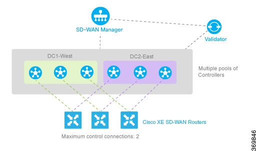
You might think of this scenario as one where there are redundant data centers in the same region of the world, such as in the same city, province, or country.
For an overlay network that spans a larger geography, such as across continents, you can use affinity so the Cisco IOS XE Catalyst SD-WAN devices establish control connections with data centers in their geographic region and only connect to more distant regions should their closer data centers become unavailable.
Configure high availability
Use device CLI commands to configure high availability and view status on supported SD-WAN routers.
Step 1 | Configure high availability on a Cisco IOS XE Catalyst SD-WAN device. Example: |
Step 2 | Use the show sdwan BFD sessions command to display information about the BFD sessions running on the local Cisco IOS XE Catalyst SD-WAN device. |
Control components redundancy
Cisco Catalyst SD-WAN Validator redundancy
A Cisco Catalyst SD-WAN Validator redundancy is a high-availability approach that
- uses multiple orchestrators so one is always available when devices join the network
- supports use of a DNS host name that can resolve to multiple IP addresses so devices try each address sequentially until a connection is established, and
- does not impact data traffic during a failure because orchestrators do not participate in the data plane.
Orchestrator roles
The Cisco SD-WAN Validator performs two key functions in the Cisco Catalyst SD-WAN overlay network:
- Authenticates and validates all Cisco SD-WAN Controllers and routers that attempt to join the Cisco Catalyst SD-WAN network.
- Orchestrates the control plane connections between the Cisco SD-WAN Controllers and routers, thus enabling Cisco SD-WAN Controller and routers to connect to each other in the Cisco Catalyst SD-WAN network.
The Cisco SD-WAN Validator runs as a VM on a network server.
Having multiple Cisco SD-WAN Validators ensures that one of them is always available whenever a Cisco device such as a router or a Cisco SD-WAN Controller is attempting to join the network.
Configuration of redundant Cisco Catalyst SD-WAN Validators
A vEdge Cloud router learns that it is acting as a Cisco SD-WAN Validator from its configuration. In the system vbond configuration command, specify the local IP address of the Cisco SD-WAN Validator and include the local keyword. Other Cisco IOS XE Catalyst SD-WAN devices use the system vbond configuration command without the local keyword to specify the IP address or DNS hostname of the Cisco SD-WAN Validator that those devices can connect to in order to join the overlay network and discover the other control components to establish control connections with
On Cisco SD-WAN Controllers, Cisco SD-WAN Managers and Cisco IOS XE Catalyst SD-WAN devices, when the network has only a single Cisco SD-WAN Validator, you can configure the Cisco SD-WAN Validator either as an IP address or as a host name (such as vbond.cisco.com) using the system vbond command. When the network has two or more Cisco SD-WAN Validators and they must all be reachable, you should use a DNS host name to specify the Cisco Catalyst SD-WAN Validators. If the DNS name resolves to multiple IP addresses, the Cisco IOS XE Catalyst SD-WAN device tries each Cisco Catalyst SD-WAN Validator address sequentially until it forms a successful connection.
Note that even if your Cisco Catalyst SD-WAN network has only a single Cisco SD-WAN Validator, it is recommended as a best practice that you specify a DNS host name rather than an IP address in the system vbond configuration command, because this results in a scalable configuration. Then, if you add additional Cisco SD-WAN Validators to your network, you do not need to change the configurations on any of the routers or other devices in your network.
 Note
NoteWhen configuring redundant Cisco SD-WAN Validators, ensure that:
- If there is an IP host mapping for both public and private IPs of vBond, verify that both private and public IPs exists. Also, confirm that these IPs are associated with their respective private and public colors.
- Only include IPs that the device can reach over the designated color (internet/public or MPLS/private). If an address is not reachable, the edge may attempt it and time out, impacting performance.
Recovery from a Cisco Catalyst SD-WAN Validator failure
In a network with multiple Cisco SD-WAN Validators, if one of them fails, the other Cisco SD-WAN Validators simply continue operating and are able to handle all requests by Cisco devices to join the network. From a control plane point of view, each Cisco SD-WAN Validator maintains permanent DTLS connections to each of the Cisco SD-WAN Controllers in the network.
Note however, that there are no connections between the Cisco SD-WAN Validators themselves. As long as one Cisco SD-WAN Validator is present in the domain, the Cisco Catalyst SD-WAN network is able to continue operating without interruption, because Cisco SD-WAN Controllers and routers are still able to locate each other and join the network.
Because Cisco SD-WAN Validators never participate in the data plane of the overlay network, the failure of any Cisco SD-WAN Validator has no impact on data traffic. Cisco SD-WAN Validators communicate with routers when the routers are first joining the network. The joining router establishes a transient DTLS connection with a Cisco SD-WAN Validator to learn the IP address of a Cisco SD-WAN Controller. When the Cisco IOS XE Catalyst SD-WAN device configuration lists the Cisco SD-WAN Validator address as a DNS name, the router tries each of the Cisco SD-WAN Validators in the list, one by one, until it is able to establish a DTLS connection. This mechanism allows a router to always be able to join the network, even after one of a group of Cisco SD-WAN Validators has failed.
Cisco Catalyst SD-WAN Manager server redundancy
Provides a centralized network management system that enables configuration, monitoring, and management of Cisco devices in the overlay network while maintaining redundancy through clustering.
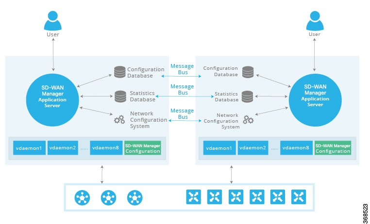
The Cisco SD-WAN Manager cluster consists of the following architectural components:
- Application server: Provides a web server for user sessions, dashboard summaries, and management of network serial files, certificates, and software upgrades.
- Configuration database: Stores the inventory, state, and configurations for all Cisco IOS XE Catalyst SD-WAN device s.
- Network configuration system: Stores all configuration information, policies, templates, and certificates.
- Statistics database: Stores statistics information collected from all Cisco devices in the overlay network.
- Message server: Acts as a communication bus among Cisco SD-WAN Manager instances to share data and coordinate operations.
The Cisco SD-WAN Manager cluster implements an active-active architecture with the following characteristics:
- Independent processing: Each Cisco SD-WAN Manager instance functions as an independent processing node.
- Load balancing: Control sessions between Cisco SD-WAN Manager instances and other controllers are arranged in a full-mesh topology.
- Database replication: Configuration and statistics databases are replicated across instances and accessible by all members.
- High availability: Network management services remain fully available if one Cisco SD-WAN Manager instance fails.
Design Considerations
NoteIn Cisco SD-WAN Release 20.6.1 and earlier releases, status information is available on the page.
NoteData nodes should be added to the cluster only after a 3-node cluster with compute+data is added.
request nms configuration-db backup path <path>Cisco Catalyst SD-WAN Controller redundancy
A Cisco Catalyst SD-WAN Controller redundancy is a control plane high availability design that
- uses two or more Cisco SD-WAN Controllers per Cisco Catalyst SD-WAN domain, and load-balances router connections when more controllers exist than connection limits.
- requires identical control policies on all Cisco SD-WAN Controllers to provide consistent route information to Cisco IOS XE Catalyst SD-WAN devices.
- maintains a full mesh of DTLS or TLS control connections and OMP sessions among Cisco SD-WAN Controllers, with permanent connections to each of the Cisco SD-WAN Validators and to Cisco IOS XE Catalyst SD-WAN devices and Cisco vEdge devices.
Cisco Catalyst SD-WAN Controller redundancy details
The Cisco SD-WAN Controllers are the central orchestrators of the control plane. They have permanent communication channels with all the Cisco devices in the network. Over the DTLS or TLS connections between the Cisco SD-WAN Controllers and Cisco SD-WAN Validators and between pairs of Cisco SD-WAN Controllers, the devices regularly exchange their views of the network, to ensure that their route tables remain synchronized. The Cisco SD-WAN Controllers pass accurate and timely route information over DTLS or TLS connections to Cisco IOS XE Catalyst SD-WAN devices.
A highly available Cisco Catalyst SD-WAN network contains two or more Cisco SD-WAN Controllers in each domain. A Cisco Catalyst SD-WAN domain can have up to 12 Cisco SD-WAN Controllers, and each router, by default, connects to two of them. When the number of Cisco SD-WAN Controllers in a domain is greater than the maximum number of controllers that a domain's routers are allowed to connect to, the Cisco Catalyst SD-WAN software load-balances the connections among the available Cisco SD-WAN Controllers.
While the configurations on all the Cisco SD-WAN Controllers must be functionally similar, the control policies must be identical. This is required to ensure that, at any time, all Cisco IOS XE Catalyst SD-WAN devices receive consistent views of the network. If the control policies are not absolutely identical, different Cisco SD-WAN Controllers might give different information to a Cisco IOS XE Catalyst SD-WAN device, and the likely result will be network connectivity issues.
NoteTo reiterate, the Cisco Catalyst SD-WAN overlay network works properly only when the control policies on all Cisco SD-WAN Controllers are identical. Even the slightest difference in the policies will result in issues with the functioning of the network.
To remain synchronized with each other, the Cisco SD-WAN Controllers establish a full mesh of DTLS or TLS control connections, as well as a full mesh of OMP sessions, between themselves. Over the OMP sessions, the Cisco SD-WAN Controllers advertise routes, TLOCs, services, policies, and encryption keys. It is this exchange of information that allows the Cisco SD-WAN Controllers to remain synchronized.
You can place Cisco SD-WAN Controllers anywhere in the network. For availability, it is highly recommended that the Cisco SD-WAN Controllers be geographically dispersed.
Each Cisco SD-WAN Controller establishes a permanent DTLS connection to each of the Cisco SD-WAN Validators. These connections allow the Cisco SD-WAN Validators to track which Cisco SD-WAN Controllers are present and operational. So, if one of the Cisco SD-WAN Controller fails, the Cisco SD-WAN Validator does not provide the address of the unavailable Cisco SD-WAN Controller to a router that is just joining the network.
To reiterate, the Cisco Catalyst SD-WAN overlay network works properly only when the control policies on all Cisco SD-WAN Controllers are identical. Even the slightest difference in the policies result in issues with the functioning of the network.
The Cisco SD-WAN Controllers are the primary controllers of the network. To maintain this control, they maintain permanent DTLS connections to all the Cisco SD-WAN Validators and Cisco IOS XE Catalyst SD-WAN devices and Cisco vEdge devices. These connections allow the Cisco SD-WAN Controllers to be constantly aware of any changes in the network topology. When a network has multiple Cisco SD-WAN Controllers:
- There is a full mesh of OMP sessions among the Cisco SD-WAN Controllers.
- Each Cisco SD-WAN Controller has a permanent DTLS connection to each Cisco SD-WAN Validator.
- The Cisco SD-WAN Controllers have permanent TLS or DTLS connections to the Cisco IOS XE Catalyst SD-WAN devices and Cisco vEdge devices.
If one of the Cisco SD-WAN Controllers fails, the other Cisco SD-WAN Controllers seamlessly take over handling control of the network. The remaining Cisco SD-WAN Controllers are able to work with Cisco IOS XE Catalyst SD-WAN devices and Cisco vEdge devices joining the network and are able to continue sending route updates to the routers. As long as one Cisco SD-WAN Controller is present and operating in the domain, the Cisco Catalyst SD-WAN network may continue operating without interruption.
Cisco IOS XE Catalyst SD-WAN Device redundancy
A redundancy is a deployment approach that
- A branch site can have two or more routers for redundancy.
- A secure control plane connection, via a TLS or DTLS connection, with one or more Cisco SD-WAN Controllers in its domain, and
- A secure data plane connection with the other routers.
Recovery from a Cisco IOS XE Catalyst SD-WAN Device failure
The Cisco IOS XE Catalyst SD-WAN device is commonly used in two ways in the Cisco Catalyst SD-WAN network: to be the Cisco Catalyst SD-WAN routers at a branch site, and to create a hub site that branch routers connect to.
A branch site can have two or more Cisco IOS XE Catalyst SD-WAN devices for redundancy.
Because both the routers receive the same routing information from the Cisco SD-WAN Controllers, each one is able to continue to route traffic if one fails, even if they are connected to different transport providers.
When using Cisco IOS XE Catalyst SD-WAN devices and Cisco vEdge devices in a hub site, you can provide redundancy by installing two hub routers. The branch routers need to connect to each of the hub routers by using SD-WAN IPsec data plane tunnels.
You can also have Cisco IOS XE Catalyst SD-WAN device provide redundancy by configuring multiple tunnel interfaces on a single router. Each tunnel interface can go through the same or different firewalls, service providers, and network clouds.
The route tables on Cisco IOS XE Catalyst SD-WAN devices and Cisco vEdge devices are populated by OMP routes received from the Cisco SD-WAN Controllers. For a site or branch with redundant routers, the route tables on both routers remain synchronized, so if either of the routers fail, the other one continues to be able to route data traffic to its destination.
Affinity on Cisco IOS XE Catalyst SD-WAN Device
A router affinity is a configuration setting that
- specifies the Cisco SD-WAN Controllers that the router is allowed to establish control connections with, and
- by default permits two OMP sessions and two control connections per TLOC.
Affinity between Cisco Catalyst SD-WAN Controllers and Cisco IOS XE Catalyst SD-WAN Device
An affinity between Cisco SD-WAN Controllers and Cisco IOS XE Catalyst SD-WAN devices is a network scale mechanism that
- places each Cisco SD-WAN Controller in a controller group
- lets a Cisco IOS XE Catalyst SD-WAN device specify the controller groups for establishing control connections, and
- uses the controller groups to establish the affinity between Cisco SD-WAN Controllers and Cisco IOS XE Catalyst SD-WAN devices.
Best practice for configuring affinity
- In the system controller-group-list command on the Cisco IOS XE Catalyst SD-WAN device, list all the controller groups that are available in the overlay network. Doing so ensures that all the Cisco SD-WAN Controllers in the overlay network are available for the affinity configuration, and provides additional redundancy if connectivity to the preferred group or groups is lost. You can manipulate the number of control connections and their priority with the maximum number of OMP sessions for the router, the maximum number of control connections for the tunnel, and the controller groups that the tunnel should not use as the preferred group (exclude-controller-group-list command). Listing all controller groups in the system controller-group-list command provides an additional layer of redundancy in situations where the Cisco IOS XE Catalyst SD-WAN device site is experiencing connectivity problems with the Cisco SD-WAN Controllers in the controller group list. To illustrate, consider a network with three controller groups (1, 2, and 3), and in which the controller group list on a Cisco IOS XE Catalyst SD-WAN device includes only groups 1 and 2 as preferred groups. In this scenario, if the router learns from the Cisco SD-WAN Validator that the Cisco SD-WAN Controllers in groups 1 and 2 are operational, but the router is unable to establish a connection to either device, it loses connectivity to the overlay network. However, if the controller group list contains all three controller groups and group 3 is set up as a less preferred (excluded) group, the router still normally prefers groups 1 and 2, but would fall back and connect to the controllers in group 3 if it cannot connect to group 1 or group 2.
- The controller groups listed in the exclude-controller-group-list command must be a subset of the controller groups configured for the entire router, in the system controller-group-list command.
- When a data center has multiple Cisco SD-WAN Controllers that use the same controller group identifier, and when the overlay network has two or more data centers, it is recommended that the number of Cisco SD-WAN Controllers in each of the controller groups be the same. For example, if Data Center 1 has three Cisco SD-WAN Controllers, all with the same group identifier (let's say, 1), Data Center 2 should also have three Cisco SD-WAN Controllers, all with the same group identifier (let's say, 2), and any additional data centers should also have three Cisco SD-WAN Controllers.
- When a data center has Cisco SD-WAN Controllers in the same controller group, the hardware capabilities—specifically, the memory and CPU—on all the Cisco SD-WAN Controllers should be identical. More broadly, all the Cisco SD-WAN Controllers in the overlay network, whether in one data center or in many, should have the same hardware capabilities. Each Cisco SD-WAN Controller should have equal capacity and capability to handle a control connection from any of the Cisco IOS XE Catalyst SD-WAN devices in the network.
- When a router has two tunnel connections and the network has two (or more) data centers, configure one tunnel interface to go to one data center and the other to the second. This configuration provides Cisco SD-WAN Controller redundancy with the minimum number of OMP sessions.
- Whenever possible in your network design, leverage affinity configurations to create fault-isolation domains.
- After affinity reconfiguration, controllers that were previously overloaded may continue to experience persistently high memory utilization. Reboot such overloaded controllers, one at a time, to recover from memory overload. The rebalancing requires a reload of the Cisco SD-WAN Controller node.
Configure controller group identifier on Cisco Catalyst SD-WAN Controllers
To participate in affinity, each Cisco SD-WAN Controller must be assigned a controller group identifier.
For Cisco SD-WAN Controllers in the same data center, they can have the same controller group identifier or different identifiers.
Configure the controller group identifier. Example:The identifier number can be from 0 through 100.
|
Configure Cisco Catalyst SD-WAN Controller groups
Set which controller groups the router can connect to by defining a system-wide list of group identifiers and, if needed, excluding specific groups per tunnel interface to control control-plane connectivity behavior.
Configuring the Cisco SD-WAN Controllers that the router is allowed to establish control connections is a two-part process:
- At the system level, configure a single list of the controller group identifiers that are present in the overlay network.
- For each tunnel interface, you can choose to restrict which controller group identifiers the tunnel interface can establish control connections with. To do this, configure an exclusion list.
At a system level, configure the identifiers of the Cisco SD-WAN Controller groups:
Before you begin
Follow these steps to configure controller groups and optional tunnel-interface exclusions:
Step 1 | Configure the system controller-group list. Example:List the Cisco SD-WAN Controller group identifiers that any of the tunnel interfaces on the Cisco IOS XE Catalyst SD-WAN device might want to establish control connections with. It is recommended that this list contain the identifiers for all the Cisco SD-WAN Controller groups in the overlay network. |
Step 2 | Configure the tunnel interface exclude-controller-group list. Example:If you want a specific tunnel interface to establish control connections to only a subset of all the Cisco SD-WAN Controller groups, configure the group identifiers to exclude: This command lists the identifiers of the Cisco SD-WAN Controller groups that this particular tunnel interface should not establish control connections with, when a Cisco SD-WAN Controller is available in configured controller groups. Ensure that the controller groups in this list are a subset of the controller groups that are configured with the system controller-group-list command. |
Step 3 | Verify the configured controller groups. To display the controller groups configured on a Cisco IOS XE Catalyst SD-WAN device, use the show sdwan running-config system command. |
Configure the maximum number of control connections
Configure device-wide and per-interface limits so that tunnel interfaces establish only the intended number of control connections to controllers, aligning control-plane scale and behavior with operational requirements.
- Limit control connections using MOS at the system level and, if needed, MCC at the tunnel-interface level.
By default, the maximum number of control connections that each tunnel interface can establish is the same as the maximum number of OMP sessions that is configured on the Cisco IOS XE Catalyst SD-WAN device. The default value for Maximum OMP sessions (MOS) is 2.
Configuring the maximum number of control connections for a tunnel interface for a Cisco IOS XE Catalyst SD-WAN device is a two-part process:
- At the system level, configure the MOS that the Cisco IOS XE Catalyst SD-WAN device can establish to Cisco SD-WAN Controllers.
- If a tunnel interface needs to connect to a different number Cisco SD-WAN Controllers than the configured MOS value, configure the maximum number of control connections that the tunnel can establish to Cisco SD-WAN Controllers,
Effectively, the maximum number of control connections a tunnel interface in a Cisco IOS XE Catalyst SD-WAN device can establish is determined by the following formula:
Max Control Connections for tunnel interface in VPN 0 = MIN(MOS, MCC)
A Cisco IOS XE Catalyst SD-WAN device establishes OMP sessions as follows:
- The device, not the individual tunnel interfaces, establishes OMP sessions with Cisco SD-WAN Controllers.
- When different tunnel interfaces on a router connect to the same Cisco SD-WAN Controller, the device creates a single OMP session with the Cisco SD-WAN Controller and the different tunnel interfaces use this single OMP session.
Before you begin
Follow these steps to configure the maximum number of control connections:
Step 1 | Modify the maximum number of OMP sessions. To modify the maximum number of OMP sessions, enter this command: Example: |
Step 2 | Modify the maximum number of control connections for a tunnel interface. NoteWhen each tunnel interface connects to the same set of Cisco SD-WAN Controllers, a Cisco IOS XE Catalyst SD-WAN device has the total number of OMP sessions equal to the configured maximum number of OMP sessions. However, if each tunnel interface connects to a different Cisco SD-WAN Controller (because of an excluded controller list), the total number of OMP sessions on the device is higher than the configured maximum number of OMP sessions, Use the following command to modify the maximum number of control connections for a tunnel interface: The number of control connections can be from 0 through 100. The default value is the maximum number of OMP sessions that is configured with the system max-OMP-sessions command. NoteIf Max Control Connections (MCC) is not configured on a tunnel interface, its default value is the same as the MOS value. |
Step 3 | Display the number of control connections for each tunnel interface. To display the actual number of control connections for each tunnel interface, use the show sdwan control affinity config command. |
Step 4 | Display the list of controllers per tunnel interface. To display a list of the Cisco SD-WAN Controllers that each tunnel interface has established control connections with, use the show sdwan control affinity status command. |
Controller group connections for Cisco IOS XE Catalyst SD-WAN Devices
A controller group connection is a Cisco Catalyst SD-WAN control-plane behavior that
- supports controller group-aware devices that connect only to controller groups in a Control Group List (CGL)
- supports controller group-unaware devices that connect exclusively to unassigned controllers in controller group 0, the default group, and
- maintains redundancy based on the device’s maximum controller connections (MCC) per TLOC using intra- and inter-controller group selection.
Controller group behaviors
Minimum supported releases: Cisco IOS XE Catalyst SD-WAN Release 17.18.1a and Cisco Catalyst SD-WAN Manager Release 20.18.1.
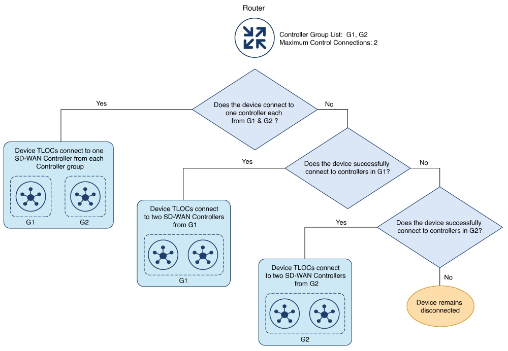
Controller group aware Cisco IOS XE Catalyst SD-WAN device is a type of device that connects only to the Cisco SD-WAN controller groups specified in their Control Group List (CGL).
When a Cisco SD-WAN controller or a controller group becomes unavailable, the device attempts to connect to the next available SD-WAN controller or controller group listed in its CGL. If all SD-WAN controllers in the CGL are unavailable, the device remains disconnected until the SD-WAN controllers become available for reconnection.
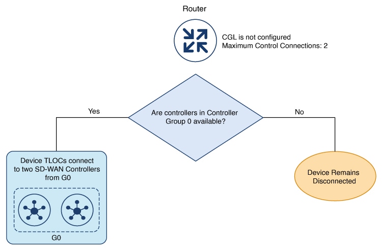
A Controller group unaware Cisco IOS XE Catalyst SD-WAN device is a type of device that operates without a configured controller group list.
It connects exclusively to controller groups that are not assigned to any controller group lists. These SD-WAN controllers are categorized under controller group 0 and are also referred to as the default group. When the SD-WAN controllers in controller group 0 are unavailable the controller group unaware device remains disconnected until the SD-WAN controllers become available for reconnection.
Controller group redundancy
Controller groups maintain redundancy by enabling Cisco Catalyst SD-WAN devices to establish connections with SD-WAN Controllers based on the device's maximum controller connections (MCC) value. For instance, if the MCC is set to 2, the device consistently connects with two controllers per TLOC.
Intra and inter controller group redundancy
When a SD-WAN controller within a configured controller group at a specific location goes down, the device selects another SD-WAN controller from the same controller group and location to maintain redundancy. This process is called intra-controller group redundancy.
If intra controller group redundancy is not possible because the SD-WAN controllers in the same controller group or location are either down or unreachable, the device redirects the connection to a SD-WAN controller from other locations. This is known as inter-controller group redundancy.
Configure control plane and data plane high availability parameters
Configure high availability parameters on the control plane and data plane to optimize controller redundancy and link failure detection in a Cisco Catalyst SD-WAN deployment.
This topic discusses the configurable high availability parameters for the control plane and the data plane.
BFD, which detects link failures as part of the Cisco Catalyst SD-WAN high availability solution, is enabled by default on all Cisco devices. BFD runs automatically on all IPsec data tunnels between Cisco IOS XE Catalyst SD-WAN devices. It does not run on the control plane (DTLS or TLS) tunnels that Cisco SD-WAN Controllers establish with all Cisco devices in the network.
Before you begin
Follow these steps to configure control plane and data plane high availability parameters:
Step 1 | Set the maximum number of control connections per tunnel. Example:A highly available Cisco Catalyst SD-WAN network contains two or more Cisco SD-WAN Controllers in each domain. A Cisco Catalyst SD-WAN domain can have up to 12 Cisco SD-WAN Controllers, and each Cisco IOS XE Catalyst SD-WAN device, by default, connects to two of them. You change this value on a per-tunnel basis: Regardless of the number of Cisco SD-WAN Controller in the domain, the Cisco IOS XE Catalyst SD-WAN device connects to the maximum number of controllers based on MCC/MOS configuration (if there are enough controllers). The Cisco IOS XE Catalyst SD-WAN device connects to the same controllers across all TLOCs. NoteTo maximize the efficiency of the load-balancing among Cisco SD-WAN Controllers, use sequential numbers when assigning system IP addresses to the Cisco IOS XE Catalyst SD-WAN devices in the domain. One example of a sequential numbering schemes is 172.1.1.1, 172.1.1.2, 172.1.1.3, and so forth. Another is 172.1.1.1, 172.1.2.1, 172.1.3.1, and so forth. |
Step 2 | Change the BFD Hello packet interval. Example:BFD sends Hello packets periodically to detect faults on the IPsec data tunnel between two Cisco IOS XE Catalyst SD-WAN devices. By default, BFD sends these packets every 1000 milliseconds (that is, once per second). To change this interval on one or more traffic flow, use the hello-interval command: The interval can be a value from 100 to 300000 milliseconds (5 minutes). Configure the interval for each tunnel connection, which is identified by a color. The color can be 3g, biz-internet, blue, bronze, custom1, custom2, custom3, default, gold, green, lte, metro-ethernet, MPLS, private1, private2, public-internet, red, or silver. |
Step 3 | Change the BFD packet interval multiplier. Example:After BFD has not received a certain number of Hello packets on a link, it declares that the link has failed. This number of packets is a multiplier of the Hello packet interval time. By default, the multiplier is 7 for hardware routers and 20 for Cloud software routers. This means that if BFD has not received a Hello packet after 7 seconds, it considers that the link has failed and implements its redundancy plan. To change the BFD packet interval multiplier, use the multiplier command: Multiplier range: 1 to 60 (integer) You configure the multiplier for each tunnel connection, which is represented by a color. |
Step 4 | Enable BFD PMTU discovery on a transport connection. Example:On each transport connection (that is, for each TLOC, or color), the Cisco Catalyst SD-WAN BFD software performs path MTU (PMTU) discovery, which automatically negotiates the MTU size in an effort to minimize or eliminate packet fragmentation on the connection. BFD PMTU discovery is enabled by default, and it is recommended that you use BFD PMTU discovery and not disable it. To explicitly enable it: With PMTU discovery enabled, the path MTU for the tunnel connection is checked periodically, about once per minute, and it is updated dynamically. With PMTU discovery enabled, 16 bytes might be required by PMTU discovery, so the effective tunnel MTU might be as low as 1452 bytes. From an encapsulation point of view, the default IP MTU for GRE is 1468 bytes, and for IPsec it is 1442 bytes because of the larger overhead. Enabling PMTU discovery adds to the overhead of the BFD packets that are sent between the Cisco IOS XE Catalyst SD-WAN devices, but does not add any overhead to normal data traffic. If PMTU discovery is disabled, the expected tunnel MTU is 1472 bytes (tunnel MTU of 1500 bytes less 4 bytes for the GRE header, 20 bytes for the outer IP header, and 4 bytes for the MPLS header). However, the effective tunnel MTU might be 1468 bytes, because the software might sometimes erroneously add 4 bytes to the header. |
Examples for affinity deployments
Configure affinity for Cisco Catalyst SD-WAN Controller s on single data center
In a Cisco Catalyst SD-WAN overlay network with multiple Cisco SD-WAN Controller s, each tunnel interface on a Cisco IOS XE Catalyst SD-WAN device defaults to establishing control connections to two Cisco SD-WAN Controller s. You can use affinity to connect to a specific subset of Cisco SD-WAN Controller s by placing them in different controller groups and configuring the Cisco IOS XE Catalyst SD-WAN device with a list of allowed controller groups.
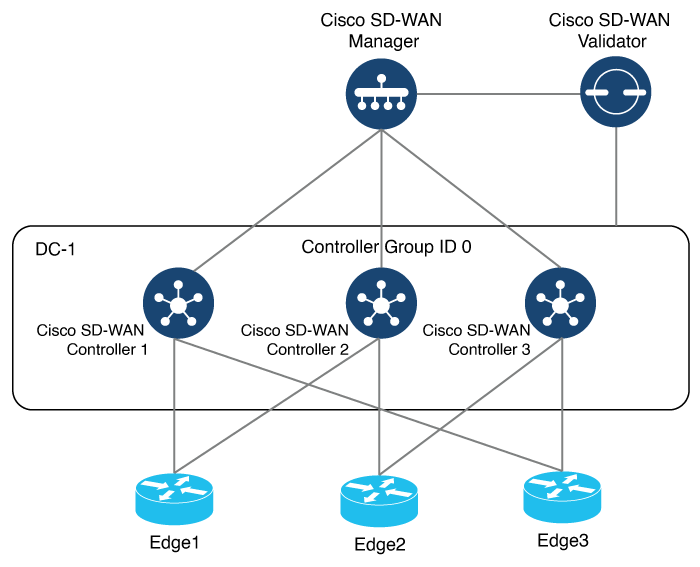 Note
NoteStep 1 | Configure the Cisco SD-WAN Controllers into controller groups. Example: | ||||||||||
Step 2 | Verify the configuration on the Cisco SD-WAN Controller. Example: | ||||||||||
Step 3 | Configure the remaining Cisco SD-WAN Controllers with their respective controller group IDs. Example: | ||||||||||
Step 4 | Configure the Cisco IOS XE Catalyst SD-WAN device with the allowed controller group list. Example: | ||||||||||
Step 5 | Verify the control connections.
| ||||||||||
Step 6 | Determine the specific Cisco SD-WAN Controllers with which the tunnel interface has established control connections. Example: |
Configure affinity for Cisco Catalyst SD-WAN Controllers on two data centers
You can use affinity to enable redundancy among data centers, for a network design in which multiple Cisco SD-WAN Controllers are spread across two or more data centers. Then, if the link between a Cisco IOS XE Catalyst SD-WAN device and one of the data centers goes down, the Cisco SD-WAN Controllers in the second data center are available to continue servicing the overlay network.
This scenario includes three Cisco SD-WAN Controllers in each of two data centers. Each of the three Cisco IOS XE Catalyst SD-WAN devices establishes a control connection to one controller in the West data center and one in the East data center.
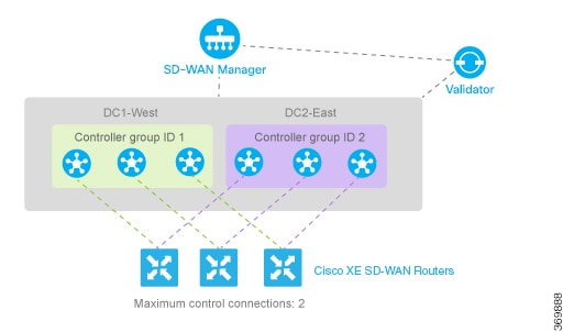
Step 1 | Configure controller group identifier 1 on controllers in DC1-West. Example: |
Step 2 | Configure controller group identifier 2 on controllers in DC2-East. Example: |
Step 3 | Set the controller group list on routers in the West to prefer DC1-West, then DC2-East. Example:We want all the Cisco IOS XE Catalyst SD-WAN devices to have a maximum of two OMP sessions, and we want each tunnel interface to have a maximum of two control connections and to not exclude any controller groups. So the only configuration that needs to be done on the routers is to set the controller group list. We want Cisco IOS XE Catalyst SD-WAN devices in the west to prefer Cisco Catalyst SD-WAN Controllers in DC1-West over DC2-East: The software evaluates the controller group list in order, so with this configuration, the Cisco IOS XE Catalyst SD-WAN devices-West prefer Cisco SD-WAN Controller group 1 (which is the West data center), and the Cisco IOS XE Catalyst SD-WAN devices - East prefer Cisco SD-WAN Controller group 2. When a Cisco IOS XE Catalyst SD-WAN devices-West router needs to connect to only one Cisco SD-WAN Controller (based on configuration), it connects only to the West data center. If the router needs to connect to two Cisco SD-WAN Controllers, it connects to one Cisco SD-WAN Controller from the West data center and another Cisco SD-WAN Controller from the East data center. |
Step 4 | Set the controller group list on routers in the East to prefer DC2-East, then DC1-West. Example: |
Step 5 | Optionally fine-tune controller group preference.
|
Configure redundant control connections on a single device
This task achieves controller redundancy with the minimum number of OMP sessions by assigning each tunnel interface to a different controller group.
When a Cisco IOS XE Catalyst SD-WAN device has two tunnel connections and the network has two (or more) data centers, you can configure redundant control connections from the Cisco IOS XE Catalyst SD-WAN device to Cisco SD-WAN Controllers in two of the data centers. It is recommended that you do this using the minimum number of OMP sessions—in this case, two. To do this, you configure one of the tunnel interfaces to go only to one of the data centers and the other to go only to the second. This configuration provides Cisco SD-WAN Controller redundancy with the minimum number of OMP sessions.
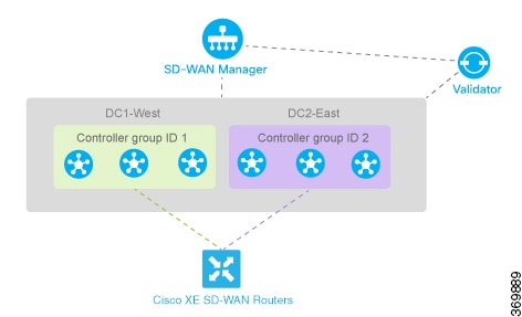
Before you begin
Follow these steps to configure redundant control connections on a single device:
Step 1 | On the Cisco IOS XE Catalyst SD-WAN device router, define the controller group list and configure the maximum number of OMP sessions to be 2. Example: |
Step 2 | On one tunnel, set the maximum number of control connections to 1. For one of the tunnels, you can use the default affinity configuration (that is, there is nothing to configure) to have this tunnel prefer a Cisco Catalyst SD-WAN Controller in group 1. You can also explicitly force this tunnel to prefer Cisco Catalyst SD-WAN Controller group 1. You do not need to configure exclude-controller-group-list 2 , because the software evaluates the controller group list in order, starting with group 1. However, you could choose to explicitly exclude Cisco SD-WAN Controller group 2. Example: |
Step 3 | On the second tunnel, set the maximum number of control connections to 1 and exclude controller group 1. Then, on the second tunnel, configure it to prefer a Cisco SD-WAN Controller in group 2. As with the other tunnel, you limit the maximum number of control connections to 1. In addition, you have to exclude controller group 1 for this tunnel. Example: |