Installing the Cisco CSR 1000v in VMware ESXi Environments

VMware ESXi Support Information

This chapter contains information about VMware tools/software and the VM requirements for Cisco CSR 1000v / Cisco IOS XE software.

The Cisco CSR 1000v can run on the VMware ESXi hypervisor. VMware ESXi runs on PCs with x86-based CPUs. You can use the same hypervisor to run several VMs.

VMware vSphere Web Client is a web application that runs on a PC and accesses VMware vCenter Server. You can use VMware vSphere Web Client software to create, configure, and manage VMs on the vCenter Server and to start/stop the Cisco CSR 1000v. The Cisco CSR 1000v boots from a virtual disk located on the data store.


Note

If you upgrade VMware ESXi, and ESXi contains an existing Cisco CSR 1000v, the interfaces of the CSR 1000v may be renamed. For example, GigabitEthernet1 may appear as GigabitEthernet4. To recover the original interface names, perform the following two Cisco IOS XE configuration commands from the console or terminal of the CSR 1000v, immediately after upgrading the VMware ESXi hypervisor:

clear platform software vnic nvtable

reload


Caution

Oversubscription of host resources can lead to a reduction of performance and your instance could become instable. We recommend that you follow the guidelines and the best practices for your host hypervisor


Note

Only ESXi hypervisor supports the FIPS mode. Ensure that you have configured the virtual machine properly to allow entropy gathering when in FIPS mode. Failing to configure ESXi properly or using another hypervisor results in the device crashing. This is applicable only for CSR 1000v release 16.9.x. The 16.10 image and later allows entropy when you use any supported hypervisor.


To find out more about installing VMware vSphere products, see VMware product documentation .
VMware Requirements

The following table specifies the supported VMware tools by Cisco CSR 1000V using Cisco IOS XE Amsterdam 17.x releases:

Cisco IOS XE Release

vSphere Web Client

vCenter Server

Cisco IOS XE 17.3.x releases

The 6.7 and 6.5 versions of the VMware vSphere Web Client are supported.

VMware ESXi 6.7 and EsXi 6.5

Cisco IOS XE 17.1.x and 17.2.x releases

The 6.5 Update 1 and 6.5 Update 2 versions of the VMware vSphere Web Client are supported.

VMware ESXi 6.5 Update 2

Cisco IOS XE 16.12 release

The 6.5 Update 1 and 6.5 Update 2 versions of the VMware vSphere Web Client are supported.

VMware ESXi 6.5 Update 2

These versions have been fully tested and meet performance benchmarks.

VMware vCenter—installation tool.

VMware vSwitch—standard or distributed vSwitches are supported.

Hard Drive—only a single hard disk drive is supported. Multiple hard disk drives on a VM are not supported.

Virtual Disk—a 8 GB virtual disk is supported.

vCPUs—the following vCPU configurations are supported:


Note

The required vCPU configuration depends on the throughput license and technology package installed. For more information, see the data sheet for your release.
  • 1 vCPU: requires minimum 4 GB RAM allocation

  • 2 vCPUs: requires minimum 4 GB RAM allocation

  • 4 vCPUs: requires minimum 4 GB RAM allocation

  • 8 vCPUs: requires minimum 4 GB RAM allocation

Virtual CPU core—one virtual CPU core is required. This needs a 64-bit processor with Virtualization Technology (VT) enabled in the BIOS setup of the host machine.

Virtual hard disk space—minimum size of 8 GB.

Virtual Network Interface Cards (vNICs)—Three or more vNICs (max. 10)—VMXNET3 or i40evf.

A default video, SCSI controller set is required, and an installed virtual CD/DVD drive.


Note

For VMware requirements—Cisco IOS XE 3.x, see VMware Requirements—Cisco IOS XE 3.x and VMware VM Requirements—Cisco IOS XE 3.x.

Supported VMware Features and Operations

VMware supports various features and operations that allow you to manage your virtual applications and perform operations such as cloning, migration, shutdown and resume.

Some of these operations cause the runtime state of the VM to be saved and then restored upon restarting. If the runtime state includes traffic-related state, then on resumption or replaying the runtime state, additional errors, statistics, or messages are displayed on the user console. If the saved state is just configuration driven, you can use these features and operations without a problem.

The table "Supported VMware Features and Operations: Storage Options (for Both vCenter Server and vSphere Client)" lists the VMware features and operations that are supported on the Cisco CSR 1000v. For more information about VMware features and operations, see the VMware Documentation .

The following VMware features and operations are not supported in all versions of the Cisco CSR 1000v, but can still be used or performed on non-supported versions at the risk of encountering dropped packets, dropped connections, and other error statistics:

  • Distributed Resource Scheduling (DRS)

  • Fault Tolerance

  • Resume

  • Snapshot

  • Suspend

See the following sections for more information.

General Features (vCenter Server)

Table 1. Supported VMware Features and Operations: General Features (for vCenter Server Only)

Supported Entities

First Supported Cisco CSR 1000v Release

Description

Cloning

Cisco IOS XE Release 3.9S

Enables cloning a virtual machine or template, or cloning a virtual machine to a template.

Migrating

Cisco IOS XE Release 3.9S

The entire state of the virtual machine as well as its configuration file, if necessary, is moved to the new host even while the data storage remains in the same location on shared storage.

vMotion

Cisco IOS XE Release 3.9S

Enables moving the VM from one physical server to another while the VM remains active.

Template

Cisco IOS XE Release 3.9S

Uses templates to create new virtual machines by cloning the template as a virtual machine.

Operations (for vCenter Server and vSphere Web Client)

Table 2. Supported VMware Features and Operations: Operations (for vCenter Server and vSphere Client)

Supported Entities

First Supported Cisco CSR 1000v Release

Description

Power On

Cisco IOS XE Release 3.9S

Powers on the virtual machine and boots the guest operating system if the guest operating system is installed.

Power Off

Cisco IOS XE Release 3.9S

Stops the virtual machine until it is powered back. The power off option performs a “hard” power off, which is analogous to pulling the power cable on a physical machine and always works.

Shut Down

Not supported.

Shut Down, or “soft” power off, leverages VMware Tools to perform a graceful shutdown of a guest operating system. In certain situations, such as when VMware Tools is not installed or the guest operating system is hung, shut down might not succeed and using the Power off option is necessary.

Suspend

Not supported

Suspends the virtual machine.

Reset/Restart

Cisco IOS XE Release 3.9S

Stops the virtual machine and restarts (reboots) it.

OVF Creation

Cisco IOS XE Release 3.9S

An OVF package consisting of several files in a directory captures the state of a virtual machine including disk files that are stored in a compressed format. You can export an OVF package to your local computer.

OVA Creation

Cisco IOS XE Release 3.9S

You can create a single OVA package file from the OVF package/template. The OVA can then be distributed more easily; for example, it may be downloaded from a website or moved via a USB key.

Table 3. Supported VMware Features and Operations: Networking Features

Supported Entities

First Supported Cisco CSR 1000v Release

Description

Custom MAC address

Cisco IOS XE Release 3.9S

From both vCenter Server and vSphere Client. Allows you to set up the MAC address manually for a virtual network adapter.

Distributed VSwitch

Cisco IOS XE Release 3.9S

From vCenter Server only. A vSphere distributed switch on a vCenter Server data center can handle networking traffic for all associated hosts on the data center.

Distributed Resources Scheduler

Cisco IOS XE Release 3.10S

Provides automatic load balancing across hosts.

NIC Load Balancing

Cisco IOS XE Release 3.9S

From both vCenter Server and vSphere Client. Load balancing and failover policies allow you to determine how network traffic is distributed between adapters and how to reroute traffic if an adapter fails.

NIC Teaming

Cisco IOS XE Release 3.9S

From both vCenter Server and vSphere Client. Allows you to set up an environment where each virtual switch connects to two uplink adapters that form a NIC team. The NIC teams can then either share the load of traffic between physical and virtual networks among some or all of its members, or provide passive failover in the event of a hardware failure or a network outage.

Note 
NIC Teaming can cause a large number of ARP packets to flood the Cisco CSR 1000v and overload the CPU. To avoid this situation, reduce the number of ARP packets and implement NIC Teaming as Active-Standby rather than Active-Active.

vSwitch

Cisco IOS XE Release 3.9S

From both vCenter Server and vSphere Client. A vSwitch is a virtualized version of a Layer 2 physical switch. A vSwitch can route traffic internally between virtual machines and link to external networks. You can use vSwitches to combine the bandwidth of multiple network adapters and balance communications traffic among them. You can also configure a vSwitch to handle a physical NIC failover.

High Availability


Note

Cisco IOS-based High Availability is not supported by the Cisco CSR 1000v. High Availability is supported on the VM host only.
Table 4. Supported VMware Features and Operations: High Availability

Supported Entities

First Supported Cisco CSR 1000v Release

Description

VM-Level High Availability

Cisco IOS XE Release 3.9S

To monitor operating system failures, VM-Level High Availability monitors heartbeat information in the VMware High Availability cluster. Failures are detected when no heartbeat is received from a given virtual machine within a user-specified time interval. VM-Level High Availability is enabled by creating a resource pool of VMs using VMware vCenter Server.

Host-Level High Availability

Cisco IOS XE Release 3.9S

To monitor physical servers, an agent on each server maintains a heartbeat with the other servers in the resource pool such that a loss of heartbeat automatically initiates the restart of all affected virtual machines on other servers in the resource pool. Host-Level High Availability is enabled by creating a resource pool of servers or hosts, and enabling high availability in vSphere.

Fault Tolerance

Cisco IOS XE Release 3.10S

Using high availability, fault tolerance is enabled on the ESXi host. When you enable fault tolerance on the VM running the Cisco CSR 1000v, a secondary VM on another host in the cluster is created. If the primary host goes down, then the VM on the secondary host will take over as the primary VM for the Cisco CSR 1000v.

Storage Options (for vCenter Server and vSphere Web Client)

Table 5. Supported VMware Features and Operations: Storage Options (for Both vCenter Server and vSphere Client)

Supported Entities

First Supported Cisco CSR 1000v Release

Description

Storage Options (for both vCenter Server and vSphere Client)

Local Storage

Cisco IOS XE Release 3.9S

Local storage is in the internal hard disks located inside your ESXi host. Local storage devices do not support sharing across multiple hosts. A datastore on a local storage device can be accessed by only one host.

External Storage Target

Cisco IOS XE Release 3.9S

You can deploy the Cisco CSR 1000v on external storage, that is, a Storage Area Network (SAN).

Mount or Pass Through of USB Storage

Cisco IOS XE Release 3.9S

You can connect USB sticks to the Cisco CSR 1000v and use them as storage devices. In ESXi, you need to add a USB controller and then assign the disk devices to the Cisco CSR 1000v.

  • Cisco CSR 1000v supports USB disk hot-plug.
  • You can use only two USB disk hot-plug devices at a time.
  • USB hub is not supported.

Deploying the Cisco CSR 1000v OVA to the VM

Deploying the Cisco CSR 1000v OVA to the VM

You can use the provided CSR 1000v OVA file package to deploy the Cisco CSR 1000v to the VM. The OVA package includes an OVF file that contains a default VM configuration based on a Cisco IOS XE release and the supported hypervisor. (See the “Guidelines and Limitations” section of the installation configuration that is included in the OVA file.)

The OVA can be deployed using VMware vSphere or COT (Common OVF Tool).


Note

The Citrix XenServer, KVM and Microsoft Hyper-V implementations do not support deploying the VM using the .ova file. You must manually install the VM using the .iso file.

Deploying the Cisco CSR 1000v OVA to the VM using vSphere

Deploying the Cisco CSR 1000v OVA to the VM using vSphere

You can use the provided CSR 1000v OVA file package to deploy the Cisco CSR 1000v to the VM. The OVA package includes an OVF file that contains a default VM configuration based on a Cisco IOS XE release and the supported hypervisor. (See the “Guidelines and Limitations” section of the installation configuration that is included in the OVA file.)


Note

The Citrix XenServer, KVM and Microsoft Hyper-V implementations do not support deploying the VM using the .ova file. You must manually install the VM using the .iso file.

Restrictions and Requirements

The following restrictions apply when deploying the OVA package to the VM:

  • (Cisco IOS XE Releases 3.10S and 3.11S) The OVA package only creates a VM with 4 virtual CPUs. To change to the 1 or 2 virtual CPU configuration, first deploy the OVA template, and then use vSphere to change the virtual CPU configuration and the required RAM allocation.

If the virtual CPU configuration is changed, the Cisco CSR 1000v must be rebooted. Changing the RAM allocation does not require rebooting the Cisco CSR 1000v. Beginning with Cisco IOS XE 3.12S, the OVA package provides an option to select the virtual CPU configuration.

  • When deploying the OVA, the VM requires two virtual CD/DVD drives, one for the OVF environment file and one for the .iso file.

  • When HSRP or IPV6 link local runs in regular VMware environments and the vSwitch has a redundant uplink of 2 vmnics connected to the same L2 segment, the VMswitch physical uplinks will be connected in a loop or both uplinks will be connected to a switched infrastructure. This process leads to l2 flooding. For more information on addressing this scenario from the VMware side, refer to this link: https://kb.vmware.com/s/article/59235.

Deploying the OVA to the VM

Perform the following steps in VMware vSphere Client:

SUMMARY STEPS

  1. Log in to the VMware vSphere Client.
  2. From the vSphere Client Menu Bar, choose File > Deploy OVF Template.
  3. In the OVA Wizard, point the source to the Cisco CSR 1000v OVA to be deployed. Click Next.
  4. Under Name and Inventory Location, specify the name for the VM and click Next.
  5. (Cisco IOS XE Release 3.12S and later): Under Deployment Configuration, select the desired hardware configuration profile from the drop-down menu and click Next.
  6. Under Storage, select the Datastore to use for the VM. Click Next.
  7. Under Disk Format, select the disk format option:
  8. Under Network Mapping, allocate one or more virtual network interface card (vNIC) on the destination network using the drop-down list. The options for mapping the vNICs differ depending on the release version:
  9. Configure the properties for the VM.
  10. Select Power on after deployment to automatically power on the VM.
  11. Click Finish to deploy the OVA.

DETAILED STEPS


Step 1

Log in to the VMware vSphere Client.

Step 2

From the vSphere Client Menu Bar, choose File > Deploy OVF Template.

Step 3

In the OVA Wizard, point the source to the Cisco CSR 1000v OVA to be deployed. Click Next.

OVF Template Details appears, showing information about the OVA. Click Next.

Step 4

Under Name and Inventory Location, specify the name for the VM and click Next.

Step 5

(Cisco IOS XE Release 3.12S and later): Under Deployment Configuration, select the desired hardware configuration profile from the drop-down menu and click Next.

Step 6

Under Storage, select the Datastore to use for the VM. Click Next.

Step 7

Under Disk Format, select the disk format option:

  • Thick Provision Lazy Zeroed

  • Thick Provision Eager Zeroed

Note 
The Thin Provision option is not supported. The Thick Provision Eager Zeroed option takes longer to install but provides better performance.

Click Next.

Step 8

Under Network Mapping, allocate one or more virtual network interface card (vNIC) on the destination network using the drop-down list. The options for mapping the vNICs differ depending on the release version:

  • (Cisco IOS XE Release 3.11S and later, and IOS XE Denali 16.2 and later): Select the network mappings for the 3 default vNICs created during the OVA deployment. You can choose which vNIC will map to the router’s management interface when setting the bootstrap properties (see table "Bootstrap Properties for Cisco IOS XE Release 3.11S and Later" below).

    Note 
    After you make any change to the bootstrap properties the system assumes that you are starting with a fresh VM. So when the VM restarts, all pre-existing networking configuration will have been removed..
  • (Cisco IOS XE Release 3.10S and earlier) The vNIC allocated in this step is mapped to the GigabitEthernet0 management interface on the router.

Select the vNIC to connect at Power On. Click Next.

When the Cisco CSR 1000v installation using the OVA is complete, two additional vNICS are allocated. The Cisco CSR 1000v supports up to ten vNICs; additional vNICs must be manually created on the VM.

The Properties screen displays.

Step 9

Configure the properties for the VM.

Note 

After you make any change to the bootstrap properties the system assumes that you are starting with a fresh VM. So when the VM restarts, all pre-existing networking configuration will have been removed.

The available properties differ depending on the Cisco IOS XE release that you are using. See the tables below for the OVA bootstrap properties for the relevant release of Cisco IOS XE.

Note 
The bootstrap properties are optional when creating the VM. You can set these properties to easily provision the VM before starting it up.
Table 6. OVA Bootstrap Properties for Cisco IOS XE Release 3.11S and Later

Property

Description

Bootstrap Properties

Console

(Cisco IOS XE 3.17S and later, and Denali 16.2 and later)

Configures the console mode.

Possible values: auto, virtual, serial

Login Username

Sets the login username for the router.

Login Password

Sets the login password for the router.

Management Interface

Designates the management interface for the Cisco CSR 1000v. The format must be GigabitEthernetx or GigabitEthernetx.xxx.

Note 
The GigabitEthernet0 interface is no longer supported beginning in Cisco IOS XE Release 3.11S.

Management vLAN

Configures the dot1Q VLAN interface. Requires the management interface to be configured using the GigabitEthernetx.xxx format.

Management Interface IPv4 Address/Mask

Configures the IPv4 address and subnet mask for the management interface.

Management IPv4 Default Gateway

(Cisco IOS XE Release 3.11S through 3.17S, and Denali 16.2 and later)

Configures the IPv4 management default gateway address. If using DHCP, enter “dhcp” in the field.

Management IPv4 Gateway

(Cisco IOS XE Release 3.12S through 3.17S, and Denali 16.2 and later)

Configures the IPv4 management default gateway address. If using DHCP, enter “dhcp” in the field.

Management IPv4 Network

(Cisco IOS XE Release 3.12S through 3.17S, and Denali 16.2 and later)

Configures the IPv4 Network (such as “192.168.2.0/24” or “192.168.2.0 255.255.255.0”) that the management gateway should route to. If a default route (0.0.0.0/0) is desired, this may be left blank.

Remote Management IPv4 Address

(Optional) Configures the IP address used for remote management of the Cisco CSR 1000v by the REST API or by the Cisco Prime Network Services Controller. The address must be in the same subnet as the management interface address.

Note 
Beginning with Cisco IOS XE 3.13S, this option is not used if configuring the shared management interface to support REST API. See Introduction to REST API Configuration Options.

PNSC IPv4 Address

Configures the IP address of the Cisco Prime Network Services Controller.

This setting is used if you plan to remotely manage the Cisco CSR 1000v using the Cisco Prime Network Services Controller.

PNSC Agent Local Port

(Optional) Configures the Cisco Prime Network Services Controller service agent SSL port on the local Cisco CSR 1000v to receive policies from the service manager.

This setting is used if you plan to remotely manage the Cisco CSR 1000v using the Cisco Prime Network Services Controller.

PNSC Shared Secret Key

Configures the Cisco Prime Network Services Controller shared secret key for the Cisco Prime Network Services Controller agent to set the SSL certificate from the controller.

This setting is used if you plan to remotely manage the Cisco CSR 1000v using the Cisco Prime Network Services Controller.

Router name

Configures the hostname of the router.

Resource Template

(Cisco IOS XE 3.16S2 and later, and Denali 16.2 and later)

Configures the Resource Template.

Possible values: default, service_plane_medium, service_plane_heavy

Features

Enable SCP Server

Enables the IOS SCP feature.

Enable SSH Login

Enable SSH Login and Disable Telnet Login

(Enable SSH Login, Cisco IOS XE Release 3.11S)

(Enable SSH Login and Disable Telnet Login, Cisco IOS XE Release 3.12S and later, and Denali 16.2 and later)

Enables remote login using SSH and disables remote login via Telnet. Requires that the login username and password are set.

Additional Configuration Properties

Enable Password

Configures the password for privileged (enable) access.

Domain Name

Configures the network domain name.

License Boot Level

(Cisco IOS XE 3.13S and later, and Denali 16.2 and later)

Configures the license technology level that is available when the Cisco CSR 1000v boots.

Table 7. OVA Bootstrap Properties for Cisco IOS XE Release 3.9S and 3.10S

Property

Description

Bootstrap Properties

Login Username

Sets the login username for the router.

Login Password

Sets the login password for the router.

Management IPv4 Address/Mask

Sets the management gateway address/mask in IPv4 format for the GigabitEthernet0 management interface.

Management IPv4 Default Gateway

Sets the default management gateway IP address in IPv4 format for the GigabitEthernet0 management interface.

Router name

Configures the hostname of the router.

Features

Enable HTTP Server

(Cisco IOS XE Release 3.9S only)

Enables an HTTP server for system configuration and administration via a web browser.

Enable HTTPS Server

(Cisco IOS XE Release 3.10S only) Enables an HTTPS server for system configuration and administration via a web browser. Required if using the REST API to perform system configuration.

Note 
The HTTPS server is enabled by default beginning in Cisco IOS XE Release 3.11S. This field was removed.

Enable SSH Login

Enables remote login using SSH and disables remote login via Telnet. Requires that the login username and password are set.

Additional Configuration Properties

Enable Password

Configures the password for privileged (enable) access.

Domain Name

Configures the network domain name.

When finished configuring the router properties, click Next. The Ready to Complete screen displays, showing the settings to be used when the OVA is deployed.

You can also configure advanced properties after the router boots.

Step 10

Select Power on after deployment to automatically power on the VM.

Step 11

Click Finish to deploy the OVA.

The OVA deploys the .iso file and, if the “Power on after deployment” setting is selected, automatically powers on the VM. Once the VM is powered on, the Cisco CSR 1000v begins the installation and boot process. If a bootstrap configuration file was included in the OVA, the router configuration will automatically be enabled.

See Booting the Cisco CSR 1000v and Accessing the Console.


Editing the Basic Properties of Cisco CSR 1000v using vSphere

When deploying the OVA template, you have the option to set basic router properties using the vSphere GUI prior to booting, as described in Deploying the Cisco CSR 1000v OVA to the VM using vSphere. You can also set custom properties matched to Cisco IOS XE CLI commands. See Editing the Custom Properties of Cisco CSR 1000v using vSphere.


Note

The functionality described in this chapter works only when using the vSphere GUI to connect to a vCenter server. If connecting directly to a host, these options are not available.

If the VM was manually created from the .iso file, then the vSphere GUI will not provide options to set basic router properties. However, you can still set custom properties as described in Editing the Custom Properties of Cisco CSR 1000v using vSphere . If you wish to do so, you will need to add a second virtual CD/DVD drive to the VM for vCenter to pass these properties into the VM.

To edit the vApp options to set basic Cisco CSR 1000v properties, do the following:

SUMMARY STEPS

  1. In the vSphere GUI, select the Options tab.
  2. Choose vApp Options > Properties.
  3. Click on the Properties button.
  4. Select the property to be edited and click Edit.
  5. Once you have edited the property, click OK to close.

DETAILED STEPS


Step 1

In the vSphere GUI, select the Options tab.

Step 2

Choose vApp Options > Properties.

Figure 1. vApp Advanced Options for Cisco CSR 1000v

Step 3

Click on the Properties button.

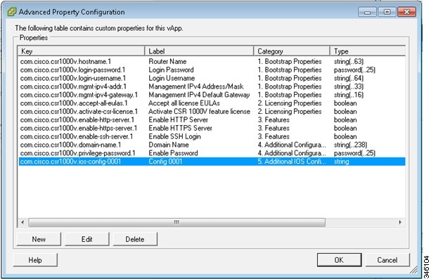
A new window opens that provides access to the properties that can be edited. See the example Advanced Property Configuration Screen below.

Note 
These properties can also be set using selected steps of the procedure described in Deploying the Cisco CSR 1000v OVA to the VM using vSphere.
Figure 2. Cisco CSR 1000v Advanced Property Configuration Screen

See the tables in Deploying the Cisco CSR 1000v OVA to the VM using vSphere for the basic Cisco CSR 1000v properties that can be edited in the vSphere vApps GUI.

Step 4

Select the property to be edited and click Edit.

Step 5

Once you have edited the property, click OK to close.


Editing the Custom Properties of Cisco CSR 1000v using vSphere

You can add custom properties to the Cisco CSR 1000v based on Cisco IOS XE CLI commands using the vSphere GUI. You can add these properties either before or after you boot the Cisco CSR 1000v. If you set these custom properties after the Cisco CSR 1000v has booted, you will need to reload the router or power-cycle the VM for the properties settings to take effect.

To edit the vApp options to add custom Cisco CSR 1000v properties, do the following:

SUMMARY STEPS

  1. In the vSphere GUI, select the Options tab.
  2. Choose vApp Options > Advanced.
  3. Click on the Properties button.
  4. Click New to add a property.
  5. Enter the information to create the new custom property based on a Cisco IOS XE CLI command:
  6. When finished, click OK.
  7. In the Advanced Property Configuration window, click OK.
  8. Reboot the Cisco CSR 1000v.

DETAILED STEPS


Step 1

In the vSphere GUI, select the Options tab.

Step 2

Choose vApp Options > Advanced.

The Advanced Property Configuration window appears.

Step 3

Click on the Properties button.

Step 4

Click New to add a property.

The Edit Property Settings window appears.

Step 5

Enter the information to create the new custom property based on a Cisco IOS XE CLI command:

Note 
Before adding a custom property, make sure that the Cisco IOS XE command upon which it is based is supported on the Cisco CSR 1000v in your release.
  1. (Optional) Enter the label. This is a descriptive string for the property.

  2. Enter the class ID as “com.cisco.csr1000v”.

  3. Assign the property an ID of “ios-config-xxxx” where xxxx is a sequence number from 0001 to 9999 that determines the order in which the custom properties are applied.

  4. (Optional) Enter a description for the property.

  5. Enter the property type as “string”. This is the only type supported.

  6. Enter the default value as the Cisco IOS XE CLI command the custom property is based on.

Step 6

When finished, click OK.

Step 7

In the Advanced Property Configuration window, click OK.

Step 8

Reboot the Cisco CSR 1000v.

The router must reboot in order for the new or edited properties to take effect.


Deploying the Cisco CSR 1000v to the VM using COT

Deploying the Cisco CSR 1000v OVA to the VM using COT

You can use the provided CSR 1000v OVA file package to deploy the Cisco CSR 1000v to the VM. The OVA package includes an OVF file that contains a default VM configuration based on a Cisco IOS XE release and the supported hypervisor. (See the “Guidelines and Limitations” section of the installation configuration that is included in the OVA file.) The OVA can be deployed using VMware vSphere or COT (Common OVF Tool). This section describes how to deploy using the COT (Common OVF Tool).

The Common OVF Tool (COT) included in the Cisco CSR 1000v software package is a Linux-based application that enables you to create attributes for one or more VMs and quickly deploy VMs with the CSR 1000v software pre-installed. This tool can speed the process of deploying Cisco CSR 1000v on multiple VMs.

COT provides a simple command-line interface to enter the VM attributes into the .ova file. COT can be run either in a LINUX shell or on Mac OS X. VMware ovftools must be installed.


DANGER

The Common OVF Tool (COT) is provided without official Cisco support. Use it at your own risk.

COT Restrictions

  • COT supports deployment of the OVA package directly onto an ESXi host. The tool does not support Citrix XenServer, KVM or Microsoft Hyper-V environments.

Editing the Basic Properties of Cisco CSR 1000v using COT

Before deploying Cisco CSR 1000v using COT, you can edit the basic or custom properties of the Cisco CSR 1000v VM in the OVA package using COT.

To edit the basic properties of the OVA, use the cot edit-properties command.

cot edit-properties

-p key1 = value1 , --properties key1 = value1

Sets properties using key value pairs. Example: -p "login-username=cisco" sets the login username using a key value pair.

-o output

Specifies the name or path to a new OVA package, if you are creating a new OVA instead of updating the existing OVA.

For more information on COT command cot edit-properties , see: http://cot.readthedocs.io/en/latest/usage_edit_properties.html

Editing the Basic Properties of Cisco CSR 1000v using COT: Example


cot edit-properties csr1000v-universalk9.ova
-p "login-username=cisco" 
  
-p "login-password=cisco" 
-o csr1000v-universalk9-customized.ova 
\# save modifications to a new OVA
cot info csr1000v-universalk9-customized.ova
  # verify the new values of properties in the OVA
(...)
Properties:
  <config-version>                                        "1.0"
  Router Name                                             ""
  Login Username                                          "cisco"
  Login Password                                          "cisco"
  Management Interface                                    "GigabitEthernet1"
  Management VLAN                                         ""
  Management Interface IPv4 Address/Mask                  ""

The table below shows the cot edit-properties command and arguments used in the above example.

Script Step

Description


cot edit propertie
s csr1000v-universalk9.ova

Edits the basic environment properties of this OVA (csr1000v-universalk9.ova).


-p "login-username=cisco"

Sets the bootstrap login username.


-p "login-password=cisco"

Sets the bootstrap login password.


-o "csr1000v-universalk9-customized.ova"

Saves a modified OVA, which contains config commands from the text file.

Editing the Custom Properties of Cisco CSR 1000v using COT

Before doing the procedures shown in section Deploying the Cisco CSR 1000v VM using COT, you can edit custom properties, for example to include Cisco IOS XE CLI commands.

To edit the custom properties of the OVA, use one of the following two commands:

cot edit-properties

Use the cot edit-properties command to pre-apply a small number of configuration commands to the OVA. (Otherwise, for a larger number of commands, consider using the cot inject-config command; see cot inject-config.)

For further details about the cot edit-properties command, see http://cot.readthedocs.io/en/latest/usage_edit_properties.html .

Synopsis and Description

cot edit-properties ova-filename

-o output

Specifies the name or path to a new OVA package, if you are creating a new OVA instead of updating the existing OVA.

-c config-file

Specifies the name of a text file containing IOS XE commands to be added to the OVA.

Example

In this example, a previously created text file, iosxe_config.txt, containing IOS XE config commands is added to the OVA using the cot edit-properties command. Finally the cot info command is used to show the modified OVA.


$ cat iosxe_config.txt
  
interface GigabitEthernet1
no shutdown
ip address 192.168.100.10 255.255.255.0
!
ip route 0.0.0.0 0.0.0.0 GigabitEthernet1 192.168.100.1
$ cot edit-properties csr1000v-universalk9.ova \
     -o csr1000v-universalk9-customized.ova \
     -c iosxe_config.txt
$ cot info csr1000v-universalk9-customized.ova

...


Properties:
  <config-version>              "1.0"
  Router Name                   ""

...


  Intercloud Tunnel Interface Gateway IPv4 Address   ""
  <ios-config-0001>             "interface GigabitEthernet1"
  <ios-config-0002>             "no shutdown"
  <ios-config-0003>             "ip address 192.168.100.10 255.255.255.0"
  <ios-config-0004>             "ip route 0.0.0.0 0.0.0.0 GigabitEthernet1 192.168.100.1"

The table below shows the cot edit properties command and arguments used in the example.

Script Step

Description


cot edit properties csr1000v-universalk9.ova

Edits the custom environment properties of this OVA (csr1000v-universalk9.ova).


-o "csr1000v-universalk9-customized.ova"

New OVA, containing configuration commands from the text file.


-c iosxe_config.txt

Text file that contains IOS XE configuration commands. Each line of configuration in this file results in a entry such as com.cisco.csr1000v.ios-config-xxxx in the XML of the OVF.

cot inject-config

Use the cot inject-config command if you have a large set of configuration commands to pre-apply to the OVA; for example, if you want to add a complete running configuration. This is efficient in terms of file size and loading time as it uses plain text for the configuration commands (instead of XML). For further details about the cot inject-config command, see

http://cot.readthedocs.io/en/latest/usage_inject_config.html

Synopsis and Description

cot inject-config ova-filename

-o output

Specifies the name or path to a new OVA package, if you are creating a new OVA instead of updating the existing OVA.

-c config-file

Specifies the name of a text file, such as iosxe_config.txt , to be embedded in the OVA.

Example

In this example, the cot inject-config command adds Cisco IOS XE commands in text file iosxe_config.txt to the OVA.


$ cat iosxe_config.txt  
interface GigabitEthernet1
no shutdown
ip address 192.168.100.10 255.255.255.0
!
ip route 0.0.0.0 0.0.0.0 GigabitEthernet1 192.168.100.1
$ cot inject-config csr1000v-universalk9.ova \
     
 -o csr1000v-universalk9-customized.ova \
      -c iosxe_config.txt
$ cot info csr1000v-universalk9-customized.ova

<.. other output snipped for brevity ..>


Files and Disks:                       File Size  Capacity Device
                                       --------- --------- --------------------
  csr1000v_harddisk.vmdk                71.50 kB   8.00 GB harddisk @ SCSI 0:0
  bdeo.sh                               52.42 kB           
  README-OVF.txt                         8.53 kB           
  README-BDEO.txt                        6.75 kB           
  cot.tgz                              116.78 kB           
  csr1000v-universalk9.iso             484.80 MB           cdrom @ IDE 1:0
  config.iso                           350.00 kB           cdrom @ IDE 1:1

The table below shows the cot inject-config command and arguments used in the example.

Script Step

Description


cot inject-config 
csr1000v-universalk9.ova

Edits the custom environment properties of this OVA (csr1000v-universalk9.ova).


-o "csr1000v-universalk9-customized.ova"

Name of the new, modified OVA, containing config commands from the text file.


-c iosxe_config.txt

Name of the text file that contains IOS XE config commands.

Deploying the Cisco CSR 1000v VM using COT

To deploy the Cisco CSR 1000v VM, use the cot deploy ... esxi command as shown in the following step. Note that the following description provides general guidance. The exact steps that you need to perform may vary depending on the characteristics of your VMware environment and setup.

SUMMARY STEPS

  1. Run the cot deploy ... esxi command to deploy the Cisco CSR 1000v. The script options are described at: http://cot.readthedocs.io/en/latest/usage_deploy_esxi.html

DETAILED STEPS


Run the cot deploy ... esxi command to deploy the Cisco CSR 1000v. The script options are described at: http://cot.readthedocs.io/en/latest/usage_deploy_esxi.html

Also see the example below.

Note: The default values may vary depending on the Cisco CSR 1000v version.


Example

The table below shows an example cot deploy command, and its arguments, that is used to deploy a Cisco CSR 1000v VM in a vCenter environment.

Script Step

Description


cot deploy

-s '10.122.197.5/UCS/host/10.122.197.38'

vCenter server 10.122.197.5, target host UCS/host/10.122.197.38


-u administrator -p password

Credentials for the ESXi server. If unspecified, COT will use your userid and prompt for a password.


-n XE3.13

Name of the newly created CSR VM.


-c 1CPU-4GB

OVF hardware config profile. If this is not specified, COT displays a list of available profiles and prompts you to select one.


-N "GigabitEthernet1=VM Network"
-N "GigabitEthernet2=VM Network"
-N "GigabitEthernet3=VM Network"

Mapping each NIC in the Cisco CSR 1000v OVA to a vSwitch on the server.


esxi

Target hypervisor (currently always ESXi)


~/Downloads/csr1000v-universalk9.ova

OVA to deploy


-ds=datastore38a

Any ESXi-specific parameters—here, the datastore to use for disk storage.

Manually Creating the VM and Installing the Cisco CSR 1000v Software Using the .iso File (VMware ESXi)

Overview of Tasks for Manually Creating the Cisco CSR 1000v VM

The figure below shows the typical high-level tasks required to manually create the Cisco CSR 1000v VM. The specific procedures, terminology and the order the steps are performed may differ depending on the hypervisor being used. See the sections following for detailed steps for creating the VM.


Note

If you manually create the VM and you plan to use the Cisco CSR 1000v REST API, you must configure the HTTPS port using the Cisco IOS XE CLI.
Figure 3. Task Overview for Manually Creating the Cisco CSR 1000v VM

Manually Creating the Cisco CSR 1000v VM Using the .iso File (VMware ESXi)

The following steps are performed using VMware VSphere.

  • Location: Store with the virtual machine

While the following procedure provides general guidance for how to deploy the Cisco CSR 1000v, the exact steps that you need to perform may vary depending on the characteristics of your VMware environment and setup. The steps and screen displays in this procedure are based on VMware ESXi 5.0.

SUMMARY STEPS

  1. Download the CSR1000_esxi.iso file from the Cisco CSR 1000v software installation image package and copy it onto the VM Datastore.
  2. In the VSphere client, select Create a New Virtual Machine option.
  3. Under Configuration, select the option to create a Custom configuration, and click Next.
  4. Under Name and Location, specify the name for the VM and click Next.
  5. Under Storage, select the datastore to use for the VM. Click Next .
  6. Under Virtual Machine Version, select Virtual Machine Version 8. Click Next .
  7. Under Guest Operating System, select Linux and the “Other 2.6x Linux (64-bit) setting” from the drop-down menu. Click Next .
  8. Under CPUs, select the following settings:
  9. Under Memory, configure the supported memory size for your Cisco CSR 1000v release.
  10. Under Network, allocate at least three virtual network interface cards (vNICs).
  11. Under SCSI Controller, select LSI Logic Parallel. Click Next .
  12. Under Select a Disk, click Create a new virtual disk.
  13. Under Create a Disk, select the following:
  14. Under Advanced Options, select SCSI (0:0) for the virtual device node.
  15. On the Ready to Complete screen, click the Edit the virtual machine settings before completion. Click Continue checkbox.
  16. In the Hardware tab, click New CD/DVD Drive .
  17. In the Resources tab, click the CPU setting:
  18. Click OK.
  19. Click Finish.

DETAILED STEPS


Step 1

Download the CSR1000_esxi.iso file from the Cisco CSR 1000v software installation image package and copy it onto the VM Datastore.

Step 2

In the VSphere client, select Create a New Virtual Machine option.

Step 3

Under Configuration, select the option to create a Custom configuration, and click Next.

Step 4

Under Name and Location, specify the name for the VM and click Next.

Step 5

Under Storage, select the datastore to use for the VM. Click Next .

Step 6

Under Virtual Machine Version, select Virtual Machine Version 8. Click Next .

Note 
The Cisco CSR 1000v is not compatible with ESXi Server versions prior to 5.0.

Step 7

Under Guest Operating System, select Linux and the “Other 2.6x Linux (64-bit) setting” from the drop-down menu. Click Next .

Step 8

Under CPUs, select the following settings:

  • Number of virtual sockets (virtual CPUs)

  • Number of cores per socket

The number of cores per socket should always be set to 1, regardless of the number of virtual sockets selected. For example, a Cisco CSR 1000v with a 4 vCPU configuration should be configured as 4 sockets and 1 core per socket.

Click Next.

Step 9

Under Memory, configure the supported memory size for your Cisco CSR 1000v release.

Click Next .

Step 10

Under Network, allocate at least three virtual network interface cards (vNICs).

  1. Select the number of vNICs that you want to connect from the drop-down menu.

    Note 
    The VMware ESXi 5.0 interface only allows the creation of 4 vNICS during the initial VM creation. You can add more vNICs after the VM is created and the Cisco CSR 1000v is first booted.
  2. Add the vNICs.

    Select a different network for each vNIC.

    Select the adapter type from the drop-down menu. See the requirements sections in this guide for the supported adapter type in your release.

  3. Select all vNICs to connect at power-on.

  4. Click Next .

    Note 
    (Cisco IOS XE Release 3.10S and earlier) The first vNIC added is mapped to the GigabitiEthernet0 management interface on the Cisco CSR 1000v. All remaining vNICs are mapped to the Cisco CSR 1000v network interfaces when the VM is powered on and the router boots for the first time. For more information about how the vNICs on the VM map to the network interfaces on the router, see Mapping the Router Network Interfaces to vNICs.
    Note 
    You can add vNICs into the VM using vSphere while the Cisco CSR 1000v is running. For more information about adding vNICS to an existing VM, see the vSphere documentation.

Step 11

Under SCSI Controller, select LSI Logic Parallel. Click Next .

Step 12

Under Select a Disk, click Create a new virtual disk.

Step 13

Under Create a Disk, select the following:

  • Capacity: Disk Size

    See the requirements sections in this guide for the virtual hard disk size required in your release.

  • Disk Provisioning: select one of the following: Thick Provision Lazy Zeroed or Thick Provision Eager Zeroed.

    Note 
    The Thin Provision option is not supported. The Thick Provision Eager Zeroed option takes longer to install but provides better performance.
  • Location: Store with the Virtual Machine

Click Next.

Step 14

Under Advanced Options, select SCSI (0:0) for the virtual device node.

Step 15

On the Ready to Complete screen, click the Edit the virtual machine settings before completion. Click Continue checkbox.

Step 16

In the Hardware tab, click New CD/DVD Drive .

  1. Select the Device Type that the VM will boot from:

    Select the Datastore ISO file option to boot from the Cisco CSR 1000v .iso file. Browse to the location of the .iso file on the datastore set in step 1.

  2. In the Device Status field, select the Connect at power on checkbox.

  3. Select the Virtual Device Node CD/DVD drive on the host that the VM will boot from.

Step 17

In the Resources tab, click the CPU setting:

Set the Resource Allocation setting to Unlimited.

Step 18

Click OK.

Step 19

Click Finish.

The VM is now configured for the Cisco CSR 1000v and is ready to boot. The Cisco CSR 1000v is booted when the VM is powered on. See Booting the Cisco CSR 1000v and Accessing the Console.

Note 
To access and configure the Cisco CSR 1000v from the serial port on the ESXi host instead of the virtual VGA console, provision the VM to use this setting before powering on the VM and booting the router. For more information, see Booting the Cisco CSR 1000v and Accessing the Console.

Increasing Performance on VMware ESXi Configurations

You can improve performance on VMware ESXi configurations by performing the following:

  • Disable VMware ESXi power management.

    Choose the High Performance setting to disable power management in VMware ESXi 5.0, 5.1, 5.5, or 6.0. For more information, see the VMware Documentation .

VMware Requirements—Cisco IOS XE 3.x

The VMware requirements supported by Cisco CSR 1000v using old versions of Cisco IOS XE from 3.9 to 3.17 are shown in the following table:

Table 8. VMware Requirements for Cisco CSR 1000v (Cisco IOS XE versions 3.x)

Cisco CSR 1000v Release

VM Configuration Requirements

Cisco IOS XE Release 3.9S

VMware ESXi 5.0

8 GB virtual disk

4 virtual CPUs

4 GB of RAM

3 or more virtual network interface cards

Single hard disk

Note 
Multiple hard disk drives on a VM are not supported.

Cisco IOS XE Release 3.10S

VMware ESXi 5.0 or 5.1

8 GB virtual disk

The following virtual CPU configurations are supported:

  • 1 virtual CPU, requiring 2.5 GB minimum of RAM

  • 4 virtual CPUs, requiring 4 GB minimum of RAM

3 or more virtual network interface cards

Single hard disk

Note 
Multiple hard disk drives on a VM are not supported.

Cisco IOS XE Release 3.11S

VMware ESXi 5.0 or 5.1

8 GB virtual disk

The following virtual CPU configurations are supported:

  • 1 virtual CPU, requiring 2.5 GB minimum of RAM

  • 2 virtual CPUs, requiring 2.5 GB minimum of RAM

  • 4 virtual CPUs, requiring 4 GB minimum of RAM

3 or more virtual network interface cards

Single hard disk

Note 
Multiple hard disk drives on a VM are not supported.

Cisco IOS XE Release 3.12 and 3.13

VMware ESXi 5.0, 5.1, or 5.5

8 GB virtual disk

The following virtual CPU configurations are supported:

  • 1 virtual CPU, requiring 2.5 GB minimum of RAM

  • 2 virtual CPUs, requiring 2.5 GB minimum of RAM

  • 4 virtual CPUs, requiring 4 GB minimum of RAM

  • 8 virtual CPUs, requiring 4 GB minimum of RAM

3 or more virtual network interface cards

Single hard disk

Note 
Multiple hard disk drives on a VM are not supported.

Cisco IOS XE Release 3.14, 3.15, 3.16, 3.17

VMware ESXi 5.0, 5.1, 5.5 (VMware ESXi 5.5 update 3 is supported on Cisco IOS XE 3.16.1S and later, and on 3.17s and later.), 6.0 (VMware ESXi 6.0 is supported on Cisco IOS XE 3.16.1S and later, and 3.17S and later.)

8 GB virtual disk

The following virtual CPU configurations are supported:

  • 1 virtual CPU, requiring 4 GB minimum of RAM

  • 2 virtual CPUs, requiring 4 GB minimum of RAM

  • 4 virtual CPUs, requiring 4 GB minimum of RAM

  • 8 virtual CPUs, requiring 4 GB minimum of RAM

3 or more virtual network interface cards

Single hard disk

Note 
Multiple hard disk drives on a VM are not supported.

VMware VM Requirements—Cisco IOS XE 3.x

The VMware tools supported by Cisco CSR 1000v using versions of Cisco IOS XE from 3.9 to 3.17 are shown in the table below.

Table 9. VMware Virtual Machine Requirements (Cisco IOS XE versions 3.x)

Cisco CSR 1000v Release

Supported Tools and Requirements

Supported vSwitch

Cisco IOS XE Release 3.9S

PC running the following:

  • VMware vSphere Client 5.0

Server running the following:

  • VMware ESXi 5.0

(For more information about server requirements, see the Cisco CSR 1000V Series Cloud Services Router Release Notes .)

Installation Tool:

  • VMware vCenter

VMware standard switch

VMware distributed switch

Cisco IOS XE Release 3.10S and 3.11S

PC running the following:

  • VMware vSphere Client 5.0

Server running the following:

  • VMware ESXi 5.0 or 5.1

Installation Tool:

  • VMware vCenter

VMware standard switch

VMware distributed switch

Cisco IOS XE Release 3.12S through 3.17S

Cisco IOS XE Denali 16.2

PC running the following:

  • VMware vSphere Client 5.0, 5.1, or 5.5

Server running the following:1

  • VMware ESXi 5.0, 5.1, or 5.5 (VMware ESXi 5.5 update 3 is supported on Cisco IOS XE 3.16.1S and later, and on 3.17s and later), 6.0 (VMware ESXi 6.0 supported on Cisco IOS XE 3.16.1S and later, and 3.17S and later.)

Installation Tool:

  • VMware vCenter

VMware standard switch

VMware distributed switch

Installation Requirements—Cisco IOS XE 3.x

The table below lists the installation requirements for VMware ESXi using versions of Cisco IOS XE from 3.9 to 3.17. For Cisco IOS XE Denali 16.3 or later, see the respective release sections. For example, the VMware Requirements - Cisco IOS XE Denali 16.3 section.


Note

The Cisco CSR 1000v does not support Cisco IOS XE Denali 16.2.
Table 10. Installation Requirements for VMware ESXi (Cisco IOS XE 3.x)

VMware ESXi Requirement

Cisco IOS XE Release 3.9S

Cisco IOS XE Release 3.10S

Cisco IOS XE Release 3.11S

Cisco IOS XE Release 3.12S, 3.13S

Cisco IOS XE Release 3.14S, 3.15S, 3.16S, 3.17S

VMware ESXi version(s) supported

5.0

5.0, 5.1

5.0, 5.1

5.0, 5.1, 5.5

5.0, 5.1, 5.5 (VMware ESXi 5.5 update 3 is supported on Cisco IOS XE 3.16.1S and later, and on 3.17s and later.), 6.0 (VMware ESXi 6.0 supported on Cisco IOS XE 3.16.1S and later, and on 3.17S and later)

Supported vCPU configurations

( The required vCPU configuration depends on the throughput license and technology package installed. For more information, see the data sheet for your release)

1 vCPU: requires minimum 4 GB RAM allocation

  • 1 vCPU: requires minimum 2.5 GB RAM allocation (Not automatically supported when deploying the OVA)

  • 4 vCPUs: requires minimum 4 GB RAM allocation (If configuring Cisco Network Based Application Recognition (NBAR), or Cisco Application Visibility and Control (AVC), a 4-GB RAM allocation is required)

  • 1 vCPU: requires minimum 2.5 GB RAM allocation (Not automatically supported when deploying the OVA)

  • 2 vCPUs: requires minimum 2.5 GB RAM allocation

  • 4 vCPUs: requires minimum 4 GB RAM allocation

  • 1 vCPU: requires minimum 2.5 GB RAM allocation

  • 2 vCPUs: requires minimum 2.5 GB RAM allocation

  • 4 vCPUs: requires minimum 4 GB RAM allocation

  • 8 vCPUs: requires minimum 4 GB RAM allocation

  • 1 vCPU: requires minimum 4 GB RAM allocation (ESXi 6.0 supported on Cisco IOS XE 3.16.1S and later)

  • 2 vCPUs: requires minimum 4 GB RAM allocation

  • 4 vCPUs: requires minimum 4 GB RAM allocation

  • 8 vCPUs: requires minimum 4 GB RAM allocation

Virtual CPU cores required (Requires a 64-bit processor with Virtualization Technology (VT) enabled in the BIOS setup of the host machine.)

1

1

1

1

1

Virtual hard disk size

8 GB minimum

8 GB minimum

8 GB minimum

8 GB minimum

8 GB minimum

Supported vNICs

VMXNET3

VMXNET3

VMXNET3

VMXNET3

VMXNET3

Maximum number of vNICs supported

10

10

10

10

10

Default video, SCSI controller set

Required

Required

Required

Required

Required

Virtual CD/DVD drive installed

Required

Required

Required

Required

Required