- Cisco ASR 1001-X Router Overview
- Cisco ASR 1001-X Router Supported Hardware Components
- Preparing Your Site for Installation
- Cisco ASR 1001-X Router Power Up and Initial Configuration
- Upgrading the ROMMON and CPLD
- Cisco ASR 1001-X Router License Verification
- Removing and Replacing FRUs from the Cisco ASR 1001-X Router
- Cisco ASR 1001-X Router Specifications
- Cisco ASR 1001-X Router Signals and Pinouts
Cisco ASR 1001-X Router Supported Hardware Components
This chapter contains information about the supported hardware components on the Cisco ASR 1001-X Router, and contains the following sections:
- Supported Hardware Components
- Supported Half-Height SPAs
- Supported Small Form-Factor Pluggable (SFP and SFP+) Transceivers
- Supported NIMs
- Cisco ASR 1001-X Router Power Supplies
Supported Hardware Components
The following table lists the hardware components supported on the Cisco ASR 1001-X Router.
|
Component |
Description |
|---|---|
|
Chassis |
1 RU form factor |
|
Ethernet Ports |
Six built-in Gigabit Ethernet and two built-in 10-Gigabit Ethernet ports |
|
ESP |
A nonmodular, fixed ESP with a default throughput of 2.5 Gbps, which is upgradable with a software-activated performance license of 5 Gbps, 10 Gbps, or 20 Gbps. |
|
Route Processor |
Single integrated route processor |
|
SIP |
Integrated SIP |
|
SPA Slots |
1 half-height (HH) SPA bay |
|
NIM Slots |
1 |
|
USB Slots |
2 |
Supported Half-Height SPAs
The following table lists the supported half-height SPAs on the Cisco ASR 1001-X Router.Supported Half-Height SPAs
|
PID |
Description |
|---|---|
|
SPA-1X10GE-L-V2 |
Cisco 1-Port 10GE LAN-PHY |
|
SPA-1XCHSTM1/OC3 |
1-port Channelized STM-1/OC-3c to DS0 |
|
SPA-1XOC12-POS |
1-port OC12/STM4 POS |
|
SPA-2XOC12-POS |
2-port OC12/STM4 POS |
|
SPA-4XOC12-POS |
4-port OC-12/STM-4 POS |
|
SPA-8XOC12-POS |
8-port OC12/STM4 |
|
SPA-1XOC3-ATM-V2 |
1-port OC-3c/STM-1 ATM |
|
SPA-2X1GE-V2 |
Cisco 2-Port Gigabit Ethernet |
|
SPA-2XCT3/DS0 |
2-port Channelized T3 to DS0 |
|
SPA-2XOC3-POS |
2-port OC3/STM1 POS |
|
SPA-8XOC3-POS |
8-port OC-3/STM-1 POS |
|
SPA-1XOC48POS/RPR |
1-port OC48/STM16 POS/RPR |
|
SPA-2XOC48POS/RPR |
2-port OC48/STM16 POS/RPR |
|
SPA-2XT3/E3 |
2-port Clear Channel T3/E3 |
|
SPA-3XOC3-ATM-V2 |
3-port OC-3c/STM-1 ATM |
|
SPA-4X1FE-TX-V2 |
Cisco 4-Port Fast Ethernet (TX) |
|
SPA-4XCT3/DS0 |
4-port Channelized T3 to DS0 |
|
SPA-4XOC3-POS |
4-port OC3/STM1 POS |
|
SPA-4XOC48POS/RPR |
4-port OC48/STM16 POS/RPR Shared Port Adapters |
|
SPA-OC192POS-XFP |
1-port OC192/STM64 POS/RPR XFP Optics |
|
SPA-4XT-SERIAL |
Cisco 4-port serial SPA |
|
SPA-4XT3/E3 |
4-port Clear Channel T3/E3 |
|
SPA-5X1GE-V2 |
Cisco 5-Port Gigabit Ethernet |
|
SPA-8X1FE-TX-V2 |
Cisco 8-Port Fast Ethernet (TX) |
|
SPA-8X1GE-V2 |
Cisco 8-Port Gigabit Ethernet |
|
SPA-8XCHT1/E1 |
8-port Channelized T1/E1 to DS0 |
|
SPA-1XOC12-ATM-V2 |
1-port OC12 STM |
|
SPA-DSP |
Digital Signal Processor SPA |
|
SPA-1X10GE-WL-V2 |
Cisco 1-port 10GE LAN/WAN-PHY |
|
SPA-2CHT3-CE-ATM |
2-Port Channelized T3/E3 ATM and Circuit Emulation SPA |
|
SPA-4XOC3-POS-V2 |
4-port OC-3/STM-1 POS |
|
SPA-2X1GE-SYNCE1 |
Cisco Synchronous Ethernet SPA |
|
SPA-8XT3/E3 |
Cisco 8-Port Clear Channel T3/E3 Shared Port Adapter |
|
SPA-24CHT1-CE-ATM |
Cisco 24 Port T1/E1/J1 Circuit Emulation SPA |
|
SPA-1CHSTM1/OC3V2 |
1-Port Channelized OC-3/STM-1 SPA, Version 2 |
|
SPA-1XOC12-POS-V2 |
1-Port OC-12C/STM-4 Multirate POS SPA (license) |
|
SPA-2XOC3-POS-V2 |
2-Port OC-3C/STM-1 POS SPA (license) |
|
SPA-2XCT3/DS0-V2 |
2-Port Channelized T3 SPA, Version 2 |
|
SPA-4XCT3/DS0-V2 |
4-Port Channelized T3 SPA, Version 2 |
|
SPA-2XT3/E3-V2 |
2-Port Clear Channel T3/E3 SPA, Version 2 |
|
SPA-4XT3/E3-V2 |
4-Port Clear Channel T3/E3 SPA, Version 2 |
|
SPA-8XCHT1/E1-V2 |
8-Port Channelized T1/E1 SPA, Version 2 |
Supported Small Form-Factor Pluggable (SFP and SFP+) Transceivers
The tables below list the supported SFP optics and SFP copper interfaces on the Cisco ASR 1001-X Router.
|
PID |
Description |
|---|---|
|
SFP-GE-S |
1000BASE-SX SFP (DOM) |
|
GLC-SX-MMD |
1000BASE-SX SFP transceiver module, MMF, 850nm, DOM |
|
SFP-GE-L |
1000BASE-LX/LH SFP (DOM) |
|
GLC-LH-SMD |
1000BASE-LX/LH SFP transceiver module, MMF/SMF, 1310nm, DOM |
|
SFP-GE-Z |
1000BASE-ZX Gigabit Ethernet SFP (DOM) |
|
SFP-GE-T |
1000BASE-T SFP (NEBS 3 ESD) |
|
GLC-BX-U |
1000BASE-BX SFP, 1310NM |
|
GLC-BX-D |
1000BASE-BX SFP, 1490NM |
|
GLC-TE |
1000BASE-T SFP transceiver module for category 5 copper wire |
|
GLC-SX-MM |
GE SFP, LC connector SX transceiver |
|
GLC-LH-SM |
GE SFP, LC connector LX/LH transceiver |
|
GLC-EX-SMD |
GE SFP, LC Connector, EX transceiver |
|
GLC-ZX-SMD |
1000BASE-ZX SFP transceiver module, SMF, 1550nm, DOM |
|
DWDM-SFP |
1000BASE DWDM |
|
CWDM-SFP |
1000BASE CWDM |
|
GLC-BX40-D-I |
1000BASE BX40-D |
|
GLC-BX40-DA-I |
1000BASE BX40-DA |
|
GLC-BX40-U-I |
1000BASE BX40-U |
|
GLC-BX80-D-I |
1000BASE BX80-D |
|
GLC-BX80-U-I |
1000BASE BX80-U |
|
GLC-GE-100FX |
100BASE-FX |
|
PID |
Description |
|---|---|
|
SFP-10G-SR |
10GBASE-SR SFP+ Module for MMF |
|
SFP-10G-SR-X |
10GBASE-SR SFP Module for Extended Temp range |
|
SFP-10G-LR |
10GBASE-LR SFP+ Module for SMF |
|
SFP-10G-LR-X |
10GBASE-LR SFP Module for Extended Temp range |
|
SFP-10G-ER |
10GBASE-ER SFP+ Module for SMF |
|
SFP-10G-ZR |
10GBASE-ZR SFP+ Module for SMF |
Supported NIMs
The Cisco ASR 1001-X Router supports the following NIM form factors:
- NIM-SSD
- NIM-T1/E1
NIM-SSD
The following table lists the supported NIM with Solid State Disk (SSD) on the Cisco ASR 1001-X Router:
|
Part Number |
Description |
|---|---|
|
NIM-SSD |
NIM Carrier Card for SSD drives |
|
SSD-SATA-200G |
200 GB, SATA Solid State Disk |
|
SSD-SATA-400G |
400 GB, SATA Solid State Disk |
NIM-T1/E1
The following table lists the supported T1/E1 NIMs on the Cisco ASR 1001-X Router:
|
Part Number |
Number of Ports |
Clear-Channel Data |
MFT Packet Voice |
Unstructured E1 (G.703) Support |
Channelized Data |
|---|---|---|---|---|---|
|
NIM-1MFT-T1/E1 |
1 |
Yes |
No |
No |
No |
|
NIM-2MFT-T1/E1 |
2 |
Yes |
No |
No |
No |
|
NIM-4MFT-T1/E1 |
4 |
Yes |
No |
No |
No |
|
NIM-8MFT-T1/E1 |
8 |
Yes |
No |
No |
No |
|
NIM-1CE1T1-PRI |
1 |
Yes |
No |
Yes |
Yes |
|
NIM-2CE1T1-PRI |
2 |
Yes |
No |
Yes |
Yes |
|
NIM-8CE1T1-PRI |
8 |
Yes |
No |
Yes |
Yes |
 Note | Each port of NIM-8CE1T1-PRI supports only 15 channel groups. If any additional channel groups are created, the following error is displayed: Insufficient resources to create channel group. |
Cisco ASR 1001-X Router Power Supplies
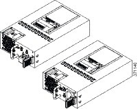
The Cisco ASR 1001-X Router supports AC and DC power supply options. The modular chassis configurations support the installation of two power supplies for redundancy. When an external power supply fails or is removed, the other power supply provides power requirements for the chassis. This allows you to hot-swap the power supply without impacting the functionality of the router.
- Power Supplies for the Cisco ASR 1001-X Router
- Cisco ASR 1001-X Power Supply Fans
- Cisco ASR 1001-X Router AC Power Supply
- Cisco ASR 1001-X Router DC Power Supply
- AC/DC Power System Input Range and Voltage for the Cisco ASR 1001-X Router
- Power Cords Supported by the Cisco ASR 1001-X Router
Power Supplies for the Cisco ASR 1001-X Router
Each Cisco ASR 1001-X Router power supply provides 250 W of output power. The power supplies are used in a 1 + 1 redundant configuration. There is no input switch on the faceplate of the power supplies. A power supply is switched from Standby to On by way of a system chassis STANDBY/ON switch. When facing the rear of the chassis, power supply slot 0 (PS0) is to the left (next to the power supply standby switch) and power supply slot 1(PS1) is to the right.
The Cisco ASR 1001-X Router supports the following power supplies:
- Cisco ASR 1001-X Router AC power supply—Provides 250 W output power with DC voltage output of +12 V. The AC power supply operates between +85 and +264 VAC. The AC power supply current shares on the 12 V output and is used in a dual hot pluggable configuration.
- Cisco ASR 1001-X Router DC power supply—Provides 242 W output power with DC voltage output of +12 V. The power supply operates between –40 and –72 VDC. The DC power supply current shares on the 12 V output and is used in a dual hot-pluggable configuration.
Note | The Cisco ASR 1001-X Router can support two AC or two DC power supplies. Do not install mixed AC and DC power supply units in the same chassis. |
The following figure shows both the DC and AC power supplies for the Cisco ASR 1001-X Router.
Cisco ASR 1001-X Power Supply Fans
The fans in the power supply module of the Cisco ASR 1001-X Router are used for cooling the power supply module itself while system-level cooling is provided by four fans within the chassis. The power supplies do not depend on the system-level fans for cooling. Fan failure is determined by fan-rotation sensors.
Note | The fans in the power supply modules will run as soon as the power supply is plugged in, even if the Standby switch is in the Standby position. |
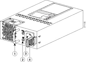
Cisco ASR 1001-X Router AC Power Supply
The Cisco ASR 1001-X Router has two AC power supplies in the rear of the chassis. The input receptacle is an IEC60320 C14 type of filtered AC inlet. The current rating on the connector is 10 A. The following figure shows the Cisco ASR 1001-X Router AC power supply.
|
1 |
Handle |
3 |
AC power connector |
|
2 |
FAIL and OK LEDs |
4 |
Retaining latch |
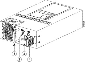
Cisco ASR 1001-X Router DC Power Supply
The Cisco ASR 1001-X Router DC input connector is a two-wire connector with connection polarity from left to right (when facing the unit) of negative (–) positive (+).
The power supply has a handle to be used for insertion and extraction. The module must be supported with one hand because of its length. The following figure shows the Cisco ASR 1001-X Router DC power supply.
|
1 |
Handle |
3 |
DC power connector |
|
2 |
FAIL and OK LEDs |
|
Retaining latch |
AC/DC Power System Input Range and Voltage for the Cisco ASR 1001-X Router
The power supply DC Input Range is –40 to –72 VDC, and the AC Input Range is +85 to +264 VAC. The following table describes the Cisco ASR 1001-X Router power supply LEDs.
|
LED Color and State |
Description |
|---|---|
|
OK - (Solid green) |
Input power is on and within the normal operating range. On the AC unit, the LED is solid green when the system in powered on. When the system is powered off, the LED will blink until the AC power is removed. |
|
OK - (Blinking Green at the rate of one blink per second) |
Input power that is within the normal operating range is being supplied, but the Standby switch is in the Standby position (and not in the On position). |
|
Fail - (Red) |
Power output has failed. |
|
Off |
Power supply is shut down. |
Power Cords Supported by the Cisco ASR 1001-X Router
The following table lists the power cords that are supported by the Cisco ASR 1001-X Router.
|
Power Cord Item Number |
Description |
|---|---|
|
CAB-AC |
Power Cord, 110 V |
|
CAB-ACA Plug |
Power Cord, Australia, 10 A |
|
CAB-ACC |
Power Cord, China |
|
CAB-ACE AC |
Power Cord, Europe, C13, CEE 7, 1.5 M |
|
CAB-ACI AC |
Power Cord, Italy, C13, CEI 23-16, 2.5 m |
|
CAB-ACR AC |
Power Cord, Argentina, C13, EL 219 (IRAM 2073), 2.5m |
|
CAB-ACS AC |
Power Cord, Switzerland, C13, IEC 60884-1, 2.5 m |
|
CAB-ACU AC |
Power Cord, UK, C13, BS 1363, 2.5 m |
|
CAB-IND AC |
Power Cord, India |
|
CAB-JPN AC |
Power Cord, Japan, C13, JIS C 8303, 2.5 m |
|
CAB-L620P-C13-US |
Power Cord, 250 VAC, 15A, NEMA L6-20 to C13, U.S. |
|
CAB-L620P-C13-JPN |
Power Cord, 250 VAC, 15A, NEMA L6-20 to C13, Japan |
|
CAB-C13-CBN Cabinet Jumper |
Power Cord, 250 VAC 10 A, C14-C13 Connectors |
|
CAB-C13-C14-JMPR Cabinet Jumper |
Power Cord, 250 VAC 13 A, C14-C15 Connector |
|
CAB-C13-C14-2M |
Power Cord Jumper, C13-C14 Connectors, 2-Meter Length |
|
CAB-C13-C14-AC |
Power Cord Jumper, C13-C14 Connectors, 3-Meter Length |
 Feedback