Introduction to this Document
This Release Notes document provides information about the Cisco Catalyst IR1101 Rugged Series Routers, Cisco Catalyst IR1800 Rugged Series Routers, Cisco Catalyst IR8140 Heavy Duty Series Routers, Cisco Catalyst IR8340 Rugged Series Routers, and Cisco ESR6300 Embedded Series Routers running Cisco IOS XE 17.8.1.
This document describes the new features, limitations, troubleshooting, besides providing recommended configurations, caveats, and information on how to obtain support and documentation.
 Note |
The documentation set for this product strives to use bias-free language. For purposes of this documentation set, bias-free is defined as language that does not imply discrimination based on age, disability, gender, racial identity, ethnic identity, sexual orientation, socioeconomic status, and intersectionality. Exceptions may be present in the documentation due to language that is hardcoded in the user interfaces of the product software, language used based on RFP documentation, or language that is used by a referenced third-party product. |
Cisco Catalyst IR1101 Rugged Series Router
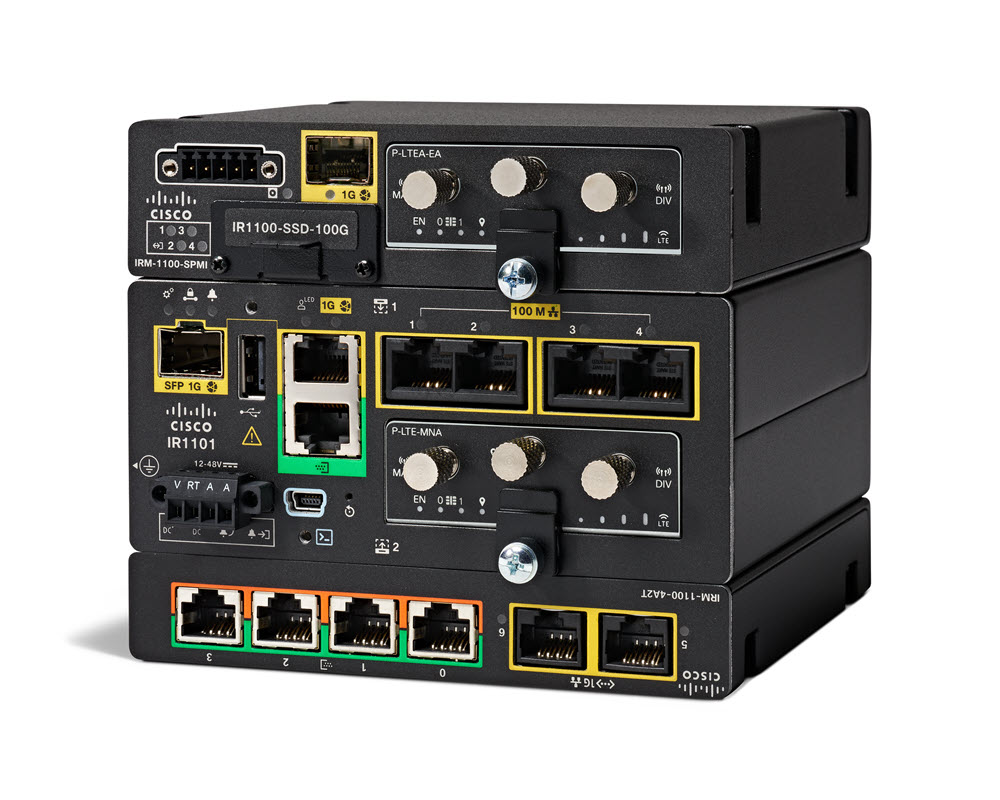
The Cisco Catalyst IR1101 Rugged Series Router is a next-generation modular industrial router, which has a base platform with additional pluggable modules that can be added. The pluggable modules provide the flexibility of adding different interfaces to the IR1101 platform, for example, a cellular module, which provides Fourth-Generation Long-Term Evolution (4G LTE) cellular networks and Third-Generation (3G) cellular networks.
The IR1101 also has expansion modules that adds key capabilities to the IR1101, such as mSATA SSD FRU, Ethernet SFP port, and digital GPIO connections. The expansion module also makes the IR1101 dual LTE capable, with one LTE module in the base and the other LTE module in the expansion module.
Note |
The IR-1100-SP expansion module is the same as the IR-1100-SPMI module, without the digital I/O and mSATA components. |
Cisco Catalyst IR1800 Rugged Series Router
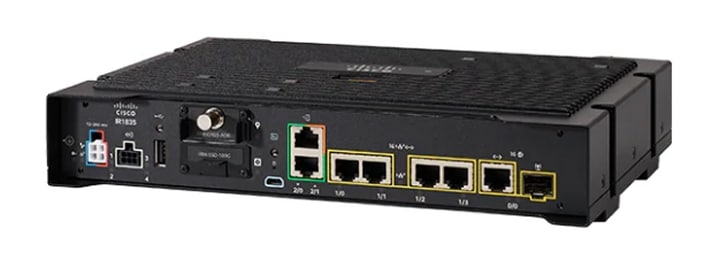
The Cisco Catalyst IR1800 Rugged Series Router is a modular industrial router. The IR1800 series has four base platforms with additional pluggable modules that can be added. The pluggable modules provide the flexibility of adding different interfaces to the base platform.
The IR1800 series features a base platform with modularity, that includes:
-
Pluggable Interface Module (PIM)
-
mSATA Module (SSDM)
-
GPS Module
-
Wi-Fi Module
The IR1800 series consists of four base platforms:
-
IR1821
-
IR1831
-
IR1833
-
IR1835
|
Feature |
IR1821 |
IR1831 |
IR1833 |
IR1835 |
|---|---|---|---|---|
|
Processor Frequency |
600 MHz |
600 MHz |
600 MHz |
1200 MHz |
|
DDR Memory |
4 GB |
4 GB |
4 GB |
8 GB |
|
Flash Storage |
4 GB |
4 GB |
4 GB |
8 GB |
|
PIM Slot |
1 |
2 |
2 |
2 |
|
Wi-Fi Pluggable Module Slot |
1 |
1 |
1 |
1 |
|
PoE |
No |
No |
Yes |
Yes |
|
SSD Module Slot |
No |
No |
Yes |
Yes |
|
GPS FRU Module Slot |
No |
No |
Yes |
Yes |
|
Digital I/O |
No |
No |
No |
Yes |
|
Asynchronous Serial Interface |
(1) RS232 DTE |
(1) RS232 DTE (1) RS232 DCE |
(1) RS232 DTE (1) RS232 DCE |
(1) RS232 DTE (1) RS232 DCE/RS485 |
Cisco Catalyst IR8140 Heavy Duty Series Router
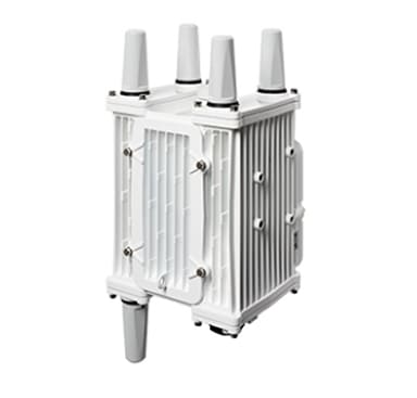
The Cisco Catalyst IR8140 Heavy Duty Series Router (IR8140H), is a next-generation modular IP 66/67 Industrial Router for outdoor use.
These are the two IR8140H models:
-
IR8140H-P-K9 (with PoE PSE)
-
IR8140H-K9 (without PoE PSE)
The IR8140H series features contains four external module slots plus two onboard WAN ports, and supports the following:
-
60-W PSU
-
CPU 1.2 GHz
-
8GB RAM
-
8GB Flash Storage
-
GPS onboard receiver
-
900-MHz WPAN – OFDM/FSK
-
4G LTE IRMH modules
-
mSATA module
-
1x 1-Gigabit Ethernet SFP WAN
-
1x 1-Gigabit Ethernet Cu WAN
-
PoE (15 W) supported only in the IR8140H-P-K9 PID
-
12VDC_OUT port (only available when PoE is not in use)
-
Battery Backup Units (BBUs): Up to three
-
2x Alarm ports (Digital I/O)
Cisco Catalyst IR8340 Rugged Series Router
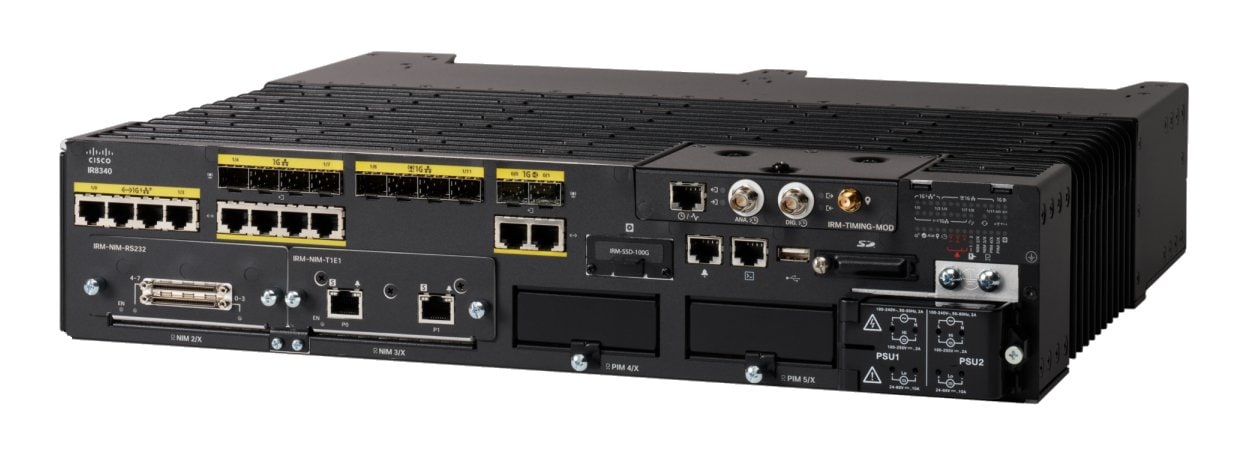
The Cisco Catalyst IR8340 Rugged Series Router, is the first all-in-one industrial-grade, integrated routing, switching, and security platform.
The IR8340 router features two Pluggable Interface Module (PIM) slots, two single-wide IRM-NIM slots, plus 12 onboard LAN ports, and two WAN ports, and supports the following:
-
150W or 250W PSU, low-voltage DC and high-voltage AC/DC options
-
PTP on LAN ports - Default, power and Dot1as profiles
-
LTE PIM
-
T1/E1 Network Interface Modules (NIM)
-
8-port Asynchronous/Synchronous Network Interface Module (NIM) IRM-NIM-RS232
-
mSATA module
-
2 x 1-G Combo WAN ports
-
4 x 1-G Copper LAN ports
-
4 x 1-G Combo LAN ports
-
4 x 1-G SFP LAN ports
-
PoE PoE+ UPoE (up to 60 W) support on LAN ports 1-4
-
2 x IN and 1 x OUT Alarm ports (RJ45)
Cisco ESR6300 Embedded Series Router
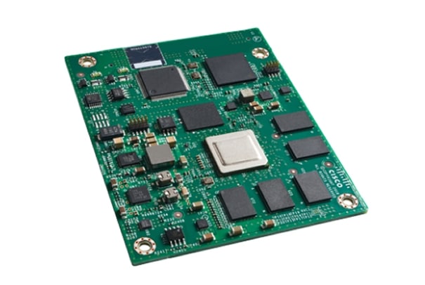
The ESR6300 is a small form factor embedded router module with a board size of 3.0 in. x 3.775 in. (76.2 mm x 95.885 mm).
The more compact design simplifies integration, and offers system integrators the ability to use the Cisco ESR6300 in a wide variety of embedded applications. The ESR module is available with a Cisco-designed cooling plate customized to the ESR, as well as without the cooling plate for system integrators who want to design their own custom thermal solution.
There are two ESR6300 SKUs:
-
ESR-6300-NCP-K9: Embedded Router Board without a cooling plate (NCP = No Cooling Plate)
-
ESR-6300-CON-K9: Embedded Router Board without a cooling plate (NCP = No Cooling Plate)
Both of the SKUs offer the following port and module interfaces:
-
Four GE LAN ports
-
Two combo GE WAN ports
-
One USB 3.0 port
-
One mSATA module interface
Interface Naming Conventions
Cisco Catalyst IR1101 Rugged Series Router
The following section shows the names of the interfaces on each of the IoT routers.
| Port |
Naming Convention |
|---|---|
|
Gigabit Ethernet combo port |
GigabitEthernet0/0/0 |
|
Gigabit Ethernet SFP port on Expansion Module |
GigabitEthernet0/0/5 |
|
Fast Ethernet ports |
FastEthernet0/0/1 FastEthernet0/0/2 FastEthernet0/0/3 FastEthernet0/0/4 |
|
Cellular Interface on IR1101 Base |
Cellular 0/1/0 Cellular 0/1/1 |
|
Cellular Interface on Expansion Module |
Cellular 0/3/0 Cellular 0/3/1 |
|
Asynchronous Serial Interface |
Async0/2/0 |
|
USB |
usbflash0: |
|
mSATA |
msata |
|
IR1101 Base Unit Alarm input |
alarm contact 0 |
|
GPIO on Expansion Module |
alarm contact 1-4 |
Cisco Catalyst IR1800 Rugged Series Router
| Port |
Naming Convention |
|---|---|
|
Gigabit Ethernet combo port |
GigabitEthernet0/0/0 |
|
Gigabit Ethernet ports |
GigabitEthernet0/1/0 GigabitEthernet0/2/0 GigabitEthernet0/3/0 GigabitEthernet0/4/0 |
|
Cellular Interface |
Cellular 0/4/0 Cellular 0/4/1 Cellular 0/5/0 Cellular 0/5/1 |
|
Asynchronous Serial Interface |
Async0/2/0 Async0/2/1 (when the base platform supports two asynchronous serial interfaces) |
|
USB |
usbflash0: |
|
mSATA |
msata |
|
GPIO |
alarm contact 1-4 |
Cisco Catalyst IR8140 Heavy Duty Series Router
| Port |
Naming Convention |
|---|---|
|
Gigabit Ethernet ports |
GigabitEthernet0/0/0 GigabitEthernet0/0/1 |
|
Cellular Interface |
Cellular 0/2/0 OR Cellular 0/3/0 |
|
SSD |
Virtual port Group0 |
|
WPAN |
Wpan 0/1/0 Wpan 0/2/0 |
|
Digital IO |
alarm contact 1-2 |
Cisco Catalyst IR8340 Rugged Series Router
| Port |
Naming Convention |
|---|---|
|
Gigabit Ethernet WAN ports |
GigabitEthernet0/0/0 GigabitEthernet0/0/1 |
|
Gigabit Ethernet LAN ports |
GigabitEthernet0/1/0 GigabitEthernet0/1/1 GigabitEthernet0/1/2 GigabitEthernet0/1/3 GigabitEthernet0/1/4 GigabitEthernet0/1/5 GigabitEthernet0/1/6 GigabitEthernet0/1/7 GigabitEthernet0/1/8 GigabitEthernet0/1/9 GigabitEthernet0/1/10 GigabitEthernet0/1/11 |
|
Cellular Interface |
Cellular 0/4/0 Cellular 0/4/1 Cellular 0/5/0 Cellular 0/5/1 |
|
NIM Interface (Asynchronous/Synchronous Serial Ports or E1/T1 ports) |
0/2/0 0/2/1 0/3/0 0/3/1 |
|
mSATA SSD |
msata |
|
GPIO |
alarm contact 1-2 |
|
USB Port |
usb0: |
|
Console Port |
Line console 0 |
Cisco ESR6300 Embedded Series Router
| Port |
Naming Convention |
|---|---|
|
Gigabit Ethernet combo port WAN Layer3 |
GigabitEthernet0/0/0 GigabitEthernet0/0/1 |
|
Gigabit Ethernet LAN Layer 2 ports |
GigabitEthernet0/1/0 GigabitEthernet0/1/1 GigabitEthernet0/1/2 GigabitEthernet0/1/3 |
|
USB Port |
usbflash0: (IOS and rommon) |
|
Console Port |
Line console 0 |
Software Images for Cisco IOS XE Release 17.8.1
Note |
You must have a Cisco.com account to download the software. |
Cisco IOS XE Release 17.8.1 includes the following Cisco images.
|
Router |
Image Type |
Filename |
|---|---|---|
|
IR1101 |
Universal |
ir1101-universalk9.17.08.01.SPA.bin |
|
NPE |
ir1101-universal9_npe.17.08.01.SPA.bin |
|
|
IR1800 |
Universal |
IR1800-universalk9.17.08.01.SPA.bin |
|
NPE |
IR1800-universal9_npe.17.08.01.SPA.bin |
|
|
IR8140 |
Universal |
IR8100-universalk9.17.08.01.SPA.bin |
|
NPE |
IR8100-universal9_npe.17.08.01a.SPA.bin |
|
|
IR8340 |
Universal |
IR8340-universalk9.17.08.01.SPA.bin |
|
NPE |
IR8340-universalk9_npe.17.08.01.SPA.bin |
|
|
ESR6300 |
Universal |
c6300-universalk9.17.08.01.SPA.bin |
The latest software downloads for the routers can be found at:
https://software.cisco.com/download/home/286323433
Click the link corresponding to your device to take you to the specific software you are looking for.
New Features in Cisco IOS XE 17.8.1
The following sections describe the major enhancements available in Cisco IOS XE 17.8.1 on each of the routers.
Major Enhancements in IR1101
Support for DSL Annex B
For the 17.8.1 release, ADSL2+ Annex B will be supported.
Annex B is not configured by default. To enable Annex B, the following command will be used.
controller VDSL 0/0/0
  capability annex-b
Support for mSATA and IO Support for IRM-1100-SPMI in CM Side
With previous software releases, the mSATA and Digital I/O on the IRM-1100-SPMI were only supported on the Expansion Module side of the IR1101. With 17.8.1, support is available on the Compute Module (CM) side with the following restrictions:
IRM-1100-SPMI installed on both sides:
-
This combination is not supported.
-
Only the mSATA and Digital I/O from the EM side will work.
-
The Digital I/O from the CM side will NOT work.
IRM-1100-SPMI installed on the CM side:
-
The mSATA and Digital I/O will work.
-
The Digital I/O instances will be numbered 1-4.
-
The SFP port will NOT work.
Major Enhancements in IR1800
There are no new features specifically for the IR1800. Check the Major Enhancements Common to all IoT Routers section.
Major Enhancements in IR8140
High Availability for WPAN
The IR8140H will now support High Availability for WPAN between two routers (each with one WPAN module). WPAN HA uses HSRP to track state between the two routers. The WPAN state (RPL routes, mesh-security sessions and keys, multicast sequence numbers) is synchronized between the two routers using a reliable UDP based protocol.
Note |
WPAN HA will not integrate with the rest of the IOS XE HA infrastructure. It is specific to WPAN. WPAN HA will only be supported between two IR8140 routers with a single WPAN interface each. This feature cannot be used together with the Dual WPAN interface feature. |
Yang Model for WPAN
Yang operational model support has been added for the information that is currently available through WPAN show commands. This includes commands for the following:
-
The WPAN interface (show wpan 0/X/0 …)
-
RPL commands (show wpan 0/X/0 rpl …)
-
meshsec (show mesh-security …)
Yang Model for BBU
Yang operational model support has been added for the Battery Backup Unit (BBU) information currently available via show commands. For example, show platform hardware battery...
Yang Model for GPS
Yang operational model support will be added for GNSS information currently available via show commands. For example, show platform hardware gnss …
Support for Dual WPAN Interfaces
The IR8140H has three UIM slots available for pluggable modules. Previous software releases allowed only one WPAN interface to be used, with the remaining slots available only for LTE modules. Release 17.8.1 includes support for having two WPAN interfaces running at the same time.
Having two WPAN modules will result in having two WPAN interfaces. The two interfaces will be independent and HA will NOT be supported between the two modules. The two interfaces will need to be configured with different PAN IDs and different IPv6 prefixes. They can be configured with either the same SSID or different SSIDs.
CAM Module support
This feature allows the IR8140 to support third party modules in the same way as the CGR1240 does. There is a CLI to configure a specific subslot as third-party, which will make cman skip the authentication for the module (since third party modules don’t have ACT2). The command is:
Router(config)#hw-module-cam ?
assign  assign eth interface up for CAM module
Check the Major Enhancements Common to all IoT Routers section for additional new features.
Major Enhancements in IR8340
Per Port enabling/disabling of Unknown unicast/ multicast Flooding
Occasionally, unknown unicast or multicast traffic is flooded to a switch port, because a MAC address has timed out or has not been learned by the router. This condition might be undesirable as flood traffic processing might impact other critical traffic. To guarantee that no unicast and multicast traffic is flooded to the port, use the switchport block unicast and switchport block multicast commands to enable flood blocking on the switch.
The interface can be a physical interface or an EtherChannel group. When you block multicast or unicast traffic for a port-channel, it is blocked for all member ports in the port-channel group.
Blocking of unicast or multicast traffic is not automatically enabled on a switched port.
High-availability Seamless Redundancy (HSR) support for IR8340
International Standard IEC 62439-3-2016 clause 5 describes High-availability Seamless Redundancy. HSR achieves the same result as Parallel Redundancy Protocol (PRP) but is designed to work in a ring topology. Instead of two parallel independent networks of any topology (LAN-A and LAN-B), HSR defines two rings with traffic in opposite directions. PortA sends traffic counter clockwise in ringA, and portB sends traffic clockwise in ringB. The packet format is different than PRP, instead of Redundancy Control Trailer (RCT) HSR introduces the HSR header with HSR Ethertype after the L2 MacSa address or VLAN tag fields.
The nodes connecting to the HSR ring are referred to as Doubly Attached Nodes implementing HSR (DANHs). Similar to PRP, Singly Attached Nodes (SANs) are attached to the HSR ring via the service of a RedBox.
Each node in the HSR ring forwards frames received from one port to the other port of the HSR pair. There are three conditions that a node will not forward frames received on one port to the other port:
-
The received frame came back around the ring to the node it originated from.
-
Unicast frame with destination MAC address belonging to upstream of the receiving node.
-
The node had already sent the same frame in the same direction. This rule is to prevent a frame from spinning in the ring in an infinite loop.
IP Device Tracking (IPDT)
The purpose of IPDT is for the router to obtain and maintain a list of devices that are connected to the router via an IP address. The main IPDT task is to keep track of connected hosts (association of MAC and IP address). In order to do this, it sends unicast Address Resolution Protocol (ARP) probes with a default interval of 30 seconds; these probes are sent to the MAC address of the host connected on the other side of the link, and use Layer 2 (L2) as the default source the MAC address of the physical interface out of which the ARP goes and a sender IP address of 0.0.0.0, based on the ARP Probe definition listed in RFC 5227.
MAC Address Notification
This feature enables the user or administrator to keep track of the MAC addresses that are learned or removed on the Layer 2 switch while forwarding the ethernet frames. This feature is required to keep a history of the MAC addresses that are learned and removed from the switch and generate notifications to the NMS periodically.
Whenever a new MAC address is learned or an old MAC address is removed, a SNMP notification is generated and sent to the NMS. A history table is also maintained for every hardware port, so that NMS can collect information by querying the MIB for the history table. This is done to make sure even if the notifications are not delivered to the NMS properly, the data is preserved on the router for the NMS to collect.
Parallel Redundancy Protocol (PRP)
PRP provides data path redundancy in the nodes for Zero recovery time. A Device that requires high availability in the data Path across the network, will need to have two nodes connecting to two independent LANs that are similar, which operates in parallel. One node connects to LAN-A and other connects to LAN-B. Such a device having redundant network obeying to PRP is known as DANP (Double attached Node for PRP).
Two PRP channels can be configured on specific port pairs Gi0/1/4, Gi0/1/5 and Gi0/1/6, Gi0/1/7. On the IR8340, each standalone router supports 2 PRP channels. They are numbered as PRP 1 and PRP 2.
IEEE 802.1Q Tunneling (QinQ)
In an L2 VPN scenario, it is necessary to keep the customers control protocol frames separate from the service-providers control protocol traffic, for example, the customer’s protocol frames must not be consumed locally by the service provider. Protocol Tunneling achieves this by encapsulating the customers protocol packets in a well known tunnel destination MAC address at the tunnel ingress, and changing it back to the protocol specific mac address at the tunnel egress. CDP, STP and VTP protocol tunneling is supported. Protocol tunneling must be explicitly turned on for the above protocols on the trunk port with QinQ enabled.
L2PT is enabled port-wide, whereas Selective QinQ and VLAN translation enable mappings on a per-port-per-vlan basis. Here, L2PT replaces the MAC DA to well known tunnel destination address for L2 control packets arriving on both mapped VLANs as well as regular (un-mapped VLANs) on the trunk port. L2 control packets arriving on mapped VLANs traverse the switch double tagged, whereas those arriving on un-mapped VLANs traverse the switch single tagged.
Similar to tunnel ports, CDP is disabled on the trunk port when VLAN mappings are configured to prevent the SP and customer switch from seeing each other.
To prevent STP BPDUs from customer and SP being seen by each other, BPDU filtering is turned ‘on’ when VLAN mappings are configured on the trunk ports.
VLAN Translation: 1:1 VLAN Mapping
VLAN translation provides the capability of carrying the customers traffic in single tagged packets across the service provider network. Since VLAN translation and selective QinQ are applied to a trunk port, the service provider gets the added benefit of being able to selectively drop or bundle all traffic that does not belong to a given set of C-VLANs and bridge accordingly in the trunk.
VLAN translation on trunk ports supports 1:1 C-VLAN to S-VLAN mapping. C-VLAN received on customer side trunk port is stripped and mapped S-VLAN is added.
Modbus Support
Use Modicon Communication Bus (MODBUS) TCP over an Ethernet network when connecting the router to devices such as intelligent electronic devices (IEDs), distributed controllers, substation routers, Cisco IP Phones, Cisco Wireless Access Points, and other network devices such as redundant substation routers.
MODBUS is a serial communications protocol for client-server communication between a router (server) and a device in the network running MODBUS client software (client). You can use MODBUS to connect a computer to a remote terminal unit (RTU) in supervisory control and data acquisition (SCADA) systems.
The client can be an IED or a human machine interface (HMI) application that remotely configure and manage devices running MODBUS TCP.
The router functions as the server. The router encapsulates a request or response message in a MODBUS TCP application data unit (ADU). A client sends a message to a TCP port on the router. The default port number is 502.
SCADA Protocol Classification Support
Support for classification and prioritization of supervisory control and data acquisition (SCADA) is achieved using ACL and QoS functionality. Scada Protocol Classification functional behavior for this release is the same as on other Cisco routers.
Storm Control - Unicast, Multicast, and Broadcast
A traffic storm occurs when packets flood the LAN, creating excessive traffic and degrading network performance. The traffic broadcast and multicast suppression (or storm control) feature prevents LAN ports from being disrupted by a broadcast, multicast and unicast traffic storm on physical interfaces.
Broadcast and Multicast Suppression monitors incoming traffic levels over a 1-second traffic storm control interval and, during the interval compares the traffic level with the traffic storm control level configured. The traffic storm control threshold level is a percentage of the total available bandwidth of the port. Each port has different storm control levels for broadcast, multicast, and unicast type of traffic.
Storm control uses rising and falling thresholds to block and then restore the forwarding of broadcast, unicast, or multicast packets.
VLAN Access Control List (VACL)
VACLs are configured globally, and the rules are applied on VLANs. VLAN ACLs are supported in both ingress and egress directions. In ingress direction, VACLs are applied after Port ACL, and before Routed ACL. In egress direction ,VACLs are applied after Routed ACL, and before Port ACL. The VLAN Map is applied to both routed and switched traffic. The VLAN Map can contain both IP and MAC ACLs to be applied to IP and non-IP traffic respectively.
Media Access Control Security (MACSec)
The MACSec feature will be supported on the IR8340 for ASIC ports. MACSec is the IEEE 802.1AE standard for authenticating and encrypting packets between two MACsec-capable devices. The MACsec Key Agreement (MKA) Protocol, defined in 802.1X-2010, provides the required keys used by the underlying MACsec protocol.
The IR8340 using MACsec accepts either MACsec or non-MACsec frames, depending on the policy associated with the MKA peer. MACsec frames are encrypted and protected with an integrity check value (ICV). When the IR8340 receives frames from the MKA peer, it decrypts them and calculates the correct ICV by using session keys provided by MKA. It compares the ICV to the ICV within the frame. If they are not identical, the frame is dropped. The IR8340 also encrypts and adds an ICV to any frames sent over the secured port (the access point used to provide the secure MAC service to a MKA peer) using the current session key
Major Enhancements in ESR6300
Further details on Dynamic Link Exchange Protocol (DLEP) and Radio-Aware Routing (RAR) can be found in the Cisco Embedded Service 6300 Series Software Configuration Guide.
DLEP Support
DLEP addresses the challenges faced when merging IP routing and radio frequency (RF) communications. Cisco provides capabilities that enable:
-
Optimal route selection based on feedback from radios
-
Faster convergence when nodes join and leave the network
-
Efficient integration of point-to-point, point-to-multipoint and broadcast multi-access radio topologies with multi-hop routing
-
Flow-controlled communications between the radio and its partner router using rate-based Quality of Service (QoS) policies
-
Dynamic shaping of fluctuating RF bandwidth in near real time to provide optimized use of actual RF bandwidth
Credit Based Radio Aware Routing Support
Radio-Aware Routing (RAR) is a mechanism that uses radios to interact with the routing protocol OSPFv3 to signal the appearance, disappearance, and link conditions of one-hop routing neighbors.
In a large mobile networks, connections to the routing neighbors are often interrupted due to distance and radio obstructions. When these signals do not reach the routing protocols, protocol timers are used to update the status of a neighbor. Routing protocols have lengthy timer, which is not recommended in mobile networks.
PPPoE extensions are used when the router communicates with the radio. In the Cisco IOS implementation of PPPoE, each individual session is represented by virtual access interface (connectivity to a radio neighbor) on which, QoS can be applied with these PPPoE extensions.
RFC5578 provides extensions to PPPoE to support credit-based flow control and session-based real time link metrics, which are very useful for connections with variable bandwidth and limited buffering capabilities (such as radio links).
Major Enhancements Common to all IoT Routers
SCADA Enhancement for TNB
This enhancement provides compatibility with TNB’s WG RTUs, including the following:
-
TNB RTUs require Reset-Link message to be sent out along with Link-Status message to ensure correct initialization of the serial. The feature can be selectively turned on using the new configuration CLI scada-gw protocol force reset-link.
-
When clock passthru is enabled and if the router hasn’t received the timestamp from the DNP3-IP master, the router’s hardware time will be sent downstream to RTU. Upon receiving a new timestamp from DNP3-IP master, the router will start sending the new timestamp sourced from DNP3-IP master to RTU.
-
The number of bufferable DNP3 events in memory will be increased from 600 to 10000.
-
The scada-gw protocol interlock command will be supported for DNP3. Previously, the support only existed for T101/T104. With this new enhancement, the router will disconnect Serial link if the DNP3-IP master is down or unreachable. Similarly, when the Serial link to RTU is down, the TCP connection to DNP3-IP master will be untethered.
-
Custom “requests” will be automatically ordered based on priority so that the user can specify them in any order that they would like to.
gNOI reset.proto
The GNMI Broker (GNMIB) has been extended to support the gRPC Network Operations Interface (gNOI) reset.proto service. This service provides functionality for restoring the device to its factory defaults via gRPC.
When the service is executed, it behaves similarly to the ‘factory-reset all’ command, and subsequently triggering a reload. Additionally, the service will maintain the current booted image. The additional steps below will be taken to comply with the reset.proto service:
-
Set the rommon BOOT variable to the current booted image and maintain it through reload following factory-reset
-
Enable autoboot to bring the device up on the current booted image following factory-reset.
gNOI os.proto
gNOI is the gRPC Network Operations Interface. gNOI defines a set of gRPC-based microservices for executing operational commands and procedure on network devices, such as OS Install, Activate, and Verification.
Through gNOI os.proto will be possible to perform operating system related tasks such as OS activation, install, detailed overview, internal OS commands, and finally to output a summary of OS operations.
Furthermore, gNOI os.proto can also be used to display the gnmib detailed state, check the gnmib operational statistics, and also to output modifiers.
Raw Socket Feature Enhancement
This enhancement allows the user to input the maximum number of retries available to the write socket. The range of the number of retries goes from 1 to 1000. The default number of retries is 10. To accommodate this feature, a new CLI has been created, raw-socket tcp max-retries <1-1000>. <1-1000> is the maximum number of retries.
Cellular Serviceability Enhancement
Enhancements have been made for cellular and GPS features as follows:
Trigger points and debug code can be enabled via controller cellular CLIs for generating and trap the debug data automatically without manual intervention. The following CLI options are available:
(config-controller)#lte modem serviceability ?
  gps               GPS debugging
  interface-resets  Interface resets/Bearer deletion
  modem-crash       Modem-crash debugging
  modem-resets      IOS initiated unknown modem-resets
The debug data includes the following:
-
Context Based debug logs (tracebacks, and GPS locations).
-
Well formatted debug messages.
-
Vendor specific debug data at a broader range.
The debug logs are located in the following location of flash:
router#dir flash:servelogs
Directory of bootflash:/servelogs/

259340  -rw-              122   Sep 7 2021 17:40:44 +00:00  gpslog-slot5-20210907-174044
259339  -rw-             1734   Sep 7 2021 12:14:07 +00:00  celllog-slot5-20210905-164628
GPS and cellular log files are created separately with file names using the timestamp at the time of the creation. These files are created as follows:
-
If the existing file has reached 10Mb, a new file will be created.
-
A new file will be created if the feature (GPS, or cellular) is completely disabled, and then re-enabled.
Related Documentation
Cisco Catalyst IR1101 Rugged Series Router
Cisco Catalyst IR1800 Rugged Series Router
Cisco Catalyst IR8140 Heavy Duty Series Router
Cisco Catalyst IR8340 Rugged Series Router
Cisco ESR6300 Embedded Series Router
Product Independent Documentation
Cisco Industrial Routers and Industrial Wireless Access Points Antenna Guide
Known Limitations
Smart Licensing Using Policy
Starting with Cisco IOS XE 17.6.1, with the introduction of Smart Licensing Using Policy, even if you configure a hostname for a product instance or device, only the Unique Device Identifier (UDI) is displayed. This change in the display can be observed in all licensing utilities and user interfaces where the hostname was displayed in earlier releases. It does not affect any licensing functionality. There is no workaround for this limitation.
The licensing utilities and user interfaces that are affected by this limitation include only the following: Cisco Smart Software Manager (CSSM), Cisco Smart License Utility (CSLU), and Smart Software Manager On-Prem (SSM On-Prem).
IOx on the ESR6300
Note |
IOx development is not supported on the ESR6300. While this is platform independent code, it is unsupported and untested on this device. |
IR1840 with two P-5GS6-GL Modules
The IR1840 does not support two P-5GS6-GL Modules installed at the same time.
Standalone MAC Authentication Bypass (MAB) Limitation
Standalone MAC Authentication Bypass (MAB) is an authentication method that grants network access to specific MAC addresses regardless of 802.1X capability or credentials.
There are two defects associated with this functionality, CSCwa33567 and CSCwb23372.
Refer to the following table for details:
|
CDET |
Details |
Release Affected |
Release Fixed |
||
|---|---|---|---|---|---|
|
CSCwa33567 |
MAB/Dot1x may not work if the global type-6 encryption setting is enabled. If users still want to use MAB/Dot1x, they should disable the type-6 encryption and enable type-7 encryption. |
17.4.X 17.5.X 17.6.1 17.6.2 17.7.1 |
17.3.5 Fixed in these future releases: 17.6.3 17.7.2 17.8.1 |
||
|
CSCwb23372 |
dACL and device-tracking features are not supported on the IR1101 and ESR6300 due to a hardware limitation. dACL is supported on the IR1800 series. Therefore, features such as MAB and Dot1x should not be used with the optional dACL/device-tracking enabled. |
|
Hardware limitation, no software fix available. |
Caveats
Caveats describe unexpected behavior in Cisco IOS XE releases. Caveats listed as open in a prior release are carried forward to the next release as either open or resolved.
The Cisco Bug Search Tool (BST) is a gateway to the Cisco bug-tracking system, which maintains a comprehensive list of defects and vulnerabilities in Cisco products and software. The BST provides you with detailed defect information about your products and software.
Open Caveats in Cisco IOS XE 17.8.1
To view the details of a caveat, click on the identifier.
|
Identifier |
Description |
Platform |
|---|---|---|
|
FN980: Profiles are not preserved when firmware is updated. |
P-5GS6-GL |
|
|
FN980: Modem not able to load correct attach profiles as in controller context. |
P-5GS6-GL |
|
|
Hidden command to configure DLEP with well-known ip address. |
ESR6300 |
|
|
VMI Neighbor counters for input packets always show as 0 with DLEP data path traffic. |
ESR6300 |
|
|
Traffic Classification stats not getting accounted on VAI for DLEP Feature. |
ESR6300 |
|
|
Correcting show commands for DLEP |
ESR6300 |
|
|
WAN SFP link goes down after reloading Peer. |
IR1800 |
|
|
With limitation on range, when pushing configuration fails from vManage for Async interfaces. |
IR1101 |
|
|
BBU alarm pin sometimes gets falsely reported to change status. |
IR8140 |
|
|
BBU cell lockout reports stale value after BBU OIR. |
IR8140 |
|
|
High CF/TE,Turnaround and Latency number after reload of router. |
IR8340 |
|
|
IR8340 throws CPP/FMAN Download errors on attaching ngsw class-map using etype classification. |
IR8340 |
|
|
GLC-T on WAN interface G 0/0/0 is admin down post booting with latest 17.8.1 |
IR8340 |
|
|
PTP Dot1as Latency accuracy is seen 13ms on latest 1781 image |
IR8340 |
|
|
PTP Forward mode functionality is not working. |
IR8340 |
|
|
Last reporter of IGMPV3 report is all "0" if receiver connected on SVI interface. |
IR8340 |
|
|
Default ignition config in sdwan running config for IoT routing platforms |
All IoT Routing platforms |
|
|
Subject-alt-name attribute in certificate trustpoint causes Windows NDES/CA to reject SCEP requests |
All IoT Routing platforms |
Resolved Caveats in Cisco IOS XE 17.8.1
To view the details of a caveat, click on the identifier.
|
Identifier |
Description |
Platform |
|---|---|---|
|
factory reset - continous reload is triggered with secure reset; 3-pass or 7-pas. |
IR8340 |
|
|
Wrong message showing during the activation app with resource crunch. |
IR8340 |
|
|
FCS errors with sync/pdel req/resp packets with PTP power profile when spanned on rx. |
IR8340 |
|
|
In DC Power Supply PID and VID is not visible. |
IR8340 |
|
|
Observed jumps on its latency and peer delay turnaround time for DOT1AS profile. |
IR8340 |
|
|
Factory reset - currently booted image gets wiped off from flash with non-secure reset. |
IR8340 |
Communications, Services, and Additional Information
-
To receive timely, relevant information from Cisco, sign up at Cisco Profile Manager.
-
To get the business impact you’re looking for with the technologies that matter, visit Cisco Services.
-
To submit a service request, visit Cisco Support.
-
To discover and browse secure, validated enterprise-class apps, products, solutions, and services, visit Cisco DevNet.
-
To obtain general networking, training, and certification titles, visit Cisco Press.
-
To find warranty information for a specific product or product family, access Cisco Warranty Finder.
Documentation Feedback
To provide feedback about Cisco technical documentation, use the feedback form available in the right pane of every online document.
Cisco Support Community
Cisco Support Community is a forum for you to ask and answer questions, share suggestions, and collaborate with your peers. Join the forum at: https://supportforums.cisco.com/index.jspa.
Cisco Bug Search Tool (BST)
The Cisco Bug Search Tool (BST) is a gateway to the Cisco bug-tracking system, which maintains a comprehensive list of defects and vulnerabilities in Cisco products and software. The BST provides you with detailed defect information about your products and software.
Abbreviated Cisco Trademarks
Cisco and the Cisco logo are trademarks or registered trademarks of Cisco and/or its affiliates in the U.S. and other countries. To view a list of Cisco trademarks, go to this URL: https://www.cisco.com/c/en/us/about/legal/trademarks.html. Third-party trademarks mentioned are the property of their respective owners. The use of the word partner does not imply a partnership relationship between Cisco and any other company. (1721R)
 Feedback