Prerequisites to Setup NCS 1010
Complete the following prerequisite tasks to prepare the NCS 1010 for seamless setup.
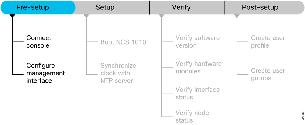
This section contains the following topics:
Connect Console Port to Terminal
The console port on the NCS 1010 is used to log into a NCS 1010 directly without a network connection using a terminal emulation program like HyperTerminal.
Procedure
|
Step 1 |
Connect the NCS 1010 to a terminal.
|
|
Step 2 |
Configure the console port to match the following default port characteristics. |
|
Step 3 |
Click OK. You should see a blinking cursor in the HyperTerminal window indicating successful connection to the console port. |
Configure Management Interface
The management interface can be used for system management and remote communication. To use the management interface for system management, you must configure an IP address and subnet mask. To use the management interface for remote communication, you must configure a static route. Use this procedure when NCS 1010 chassis is not booted using ZTP.
Before you begin
-
Consult your network administrator to procure IP addresses and a subnet mask for the management interface.
-
Ensure that the management interface is connected to the management network.
Procedure
|
Step 1 |
configure Example: |
|
Step 2 |
interface mgmtEth rack/slot/instance/port Example:Enters interface configuration mode for the management interface. |
|
Step 3 |
ipv4 address ipv4-address subnet-mask Example:Assigns an IP address and a subnet mask to the management interface. |
|
Step 4 |
no shutdown Example:Places the management interface in an "up" state. |
|
Step 5 |
exit Example:Exits the management interface configuration mode. |
|
Step 6 |
ncs1010 static address-family ipv4 unicast 0.0.0.0/0 default-gateway Example:Specifies the IP address of the default gateway to configure a static route. This IP address must be used for communication with devices on other networks. |
|
Step 7 |
Use the commit or end command. commit-Saves the configuration changes and remains within the configuration session. end-Prompts user to take one of these actions:
|
What to do next
Connect the management interface to the Ethernet network. Establish a SSH or Telnet connection to the management interface using its IP address.
Link Layer Discovery Protocol Support on Management Interface
The Link Layer Discovery Protocol (LLDP) support on management interface feature requires a system to form LLDP neighbor relationship over the system management interface, through which it advertises and learns LLDP neighbor information. This information about neighbors used to learn about the neighbors and in turn the topology of the devices for Operations, Administration, and Maintenance (OAM) purposes.
Advantages of LLDP
-
Provides support on non-Cisco devices.
-
Enables neighbor discovery between non-Cisco devices.
Limitation
-
When you disable LLDP globally, the LLDP gets disabled on all the interfaces.
 Note |
By default, LLDP is enabled for NCS 1010. But when you enable and disable LLDP in the global configuration mode, LLDP gets disabled on all the interfaces. Workaround: You must enable LLDP globally or reload the NCS1010. |
Cisco Discovery Protocol (CDP) vs LLDP
The CDP is a device discovery protocol that runs over Layer 2. Layer 2 is also known as the data link layer that runs on all Cisco devices, such as routers, bridges, access servers, and switches. This protocol allows the network management applications to automatically discover and learn about other Cisco devices that connect to the network.
The LLDP is also a device discovery protocol that runs over Layer 2. This protocol allows the network management applications to automatically discover and learn about other non-Cisco devices that connect to the network.
Interoperability between non-Cisco devices using LLDP
LLDP is also a neighbor discovery protocol that is used by network devices to advertise information about themselves to other devices on the network. This protocol runs over the data link layer, which allows two systems running different network layer protocols to learn about each other.
With LLDP, you can also access the information about a particular physical network connection. If you use a non-Cisco monitoring tool (through SNMP), LLDP helps you identify the Object Identifiers (OIDs) that the system supports. The following OIDs are supported:
-
1.0.8802.1.1.2.1.4.1.1.4
-
1.0.8802.1.1.2.1.4.1.1.5
-
1.0.8802.1.1.2.1.4.1.1.6
-
1.0.8802.1.1.2.1.4.1.1.7
-
1.0.8802.1.1.2.1.4.1.1.8
-
1.0.8802.1.1.2.1.4.1.1.9
-
1.0.8802.1.1.2.1.4.1.1.10
-
1.0.8802.1.1.2.1.4.1.1.11
-
1.0.8802.1.1.2.1.4.1.1.12
Neighbor Discovery
System advertises the LLDP TLV (Type Length Value) details over the management network using which other devices in the management network can learn about this device.
Configuring LLDP
-
LLDP full stack functionality is supported on all three management interfaces that are supported in NCS 1010.
-
You can selectively enable or disable LLDP on any of the management interfaces on demand.
-
You can selectively enable or disable LLDP transmit or receive functionality at the management interface level.
-
Information gathered using LLDP can be stored in the device Management Information Database (MIB) and queried with the Simple Network Management protocol (SNMP).
-
LLDP operational data is available in both CLI and netconf-yang interface.
Enabling LLDP Globally
When you enable LLDP globally, all interfaces that support LLDP are automatically enabled for both transmit and receive operations.
Note |
You can override this default operation at the interface to disable receive or transmit operations. |
The following table describes the global LLDP attributes that you can configure:
|
Attribute |
Default |
Range |
Description |
|---|---|---|---|
|
Holdtime |
120 |
0–65535 |
Specifies the holdtime (in sec). Holdtime refers to the time or duration that an LLDP device maintains the neighbor information before discarding. |
|
Reinit |
2 |
2–5 |
Delay (in sec) for LLDP initialization on any interface |
|
Timer |
30 |
5–65534 |
Specifies the rate at which LLDP packets are sent (in sec) |
The following example shows the commands to configure LLDP globally. The global LLDP configuration enables LLDP on all the three management interfaces.
RP/0/RP0/CPU0:ios#configure terminal
RP/0/RP0/CPU0:ios(config)#lldp management enable
RP/0/RP0/CPU0:ios(config)#lldp holdtime 30
RP/0/RP0/CPU0:ios(config)#lldp reinit 2
RP/0/RP0/CPU0:ios(config)#commit
Verification
You can verify the LLDP configuration using the show running-config lldp command.
RP/0/RP0/CPU0:ios#show running-config lldp
Tue Dec 10 10:36:11.567 UTC
lldp
timer 30
reinit 2
holdtime 120
management enable
!
You can verify the LLDP data using the show lldp interface and show lldp neighbors commands.
The output of show lldp interface command is as follows:
RP/0/RP0/CPU0:ios#show lldp interface
Mon Nov 11 14:33:58.982 IST


MgmtEth0/RP0/CPU0/0:
        Tx: enabled
        Rx: enabled
        Tx state: IDLE
        Rx state: WAIT FOR FRAME


MgmtEth0/RP0/CPU0/2:
        Tx: enabled
        Rx: enabled
        Tx state: IDLE
        Rx state: WAIT FOR FRAME


GigabitEthernet0/0/0/0:
        Tx: enabled
        Rx: enabled
        Tx state: IDLE
        Rx state: WAIT FOR FRAME
The output of show lldp neighbors command is as follows:
RP/0/RP0/CPU0ios:M-131#show lldp neighbors
Mon Dec 9 14:57:55.915 IST
Capability codes:
(R) Router, (B) Bridge, (T) Telephone, (C) DOCSIS Cable Device
(W) WLAN Access Point, (P) Repeater, (S) Station, (O) Other

Device ID Local Intf Hold-time Capability Port ID
P1C_DT_01.cisco.com GigabitEthernet0/0/0/0 120 R GigabitEthernet0/0/0/0
NCS1004-HH-10 MgmtEth0/RP0/CPU0/2 60 R MgmtEth0/RP0/CPU0/2

Total entries displayed: 2
where [DISABLED] shows that the LLDP is disabled on the interface MgmtEth0/RP0/CPU0/0.
Note |
If the RCOM interface is enabled, the output of show lldp neighbors command would include the entries for both LLDP neighbours and remote connect neighbours. |
Enabling LLDP per Management Interface
The following example shows the commands to configure LLDP at the management interface level.
RP/0/RP0/CPU0:ios(config)#interface mgmtEth 0/RP0/CPU0/X
RP/0/RP0/CPU0:ios(config-if)#lldp enable
RP/0/RP0/CPU0:ios(config-if)#commit
Disabling LLDP Transmit and Receive Operations
The following example shows the commands to disable the LLDP transmit operations at the specified management interface.
RP/0/RP0/CPU0:ios(config)#interface mgmtEth 0/RP0/CPU0/X
RP/0/RP0/CPU0:ios(config-if)#lldp transmit disable
RP/0/RP0/CPU0:ios(config-if)#commit
The following example shows the commands to disable the LLDP receive operations at the specified management interface.
RP/0/RP0/CPU0:ios(config)#interface mgmtEth 0/RP0/CPU0/X
RP/0/RP0/CPU0:ios(config-if)#lldp receive disable
RP/0/RP0/CPU0:ios(config-if)#commit
Debugging LLDP Issues
Use these commands for debugging issues in the LLDP functionality.
-
show lldp traffic
-
debug lldp all
-
debug lldp errors
-
debug lldp events
-
debug lldp packets
-
debug lldp tlvs
-
debug lldp trace
-
debug lldp verbose
Configure Telnet
This procedure allows you to establish a telnet session to the management interface using its IP address. Use this procedure when NCS 1010 chassis is not booted using ZTP.
Before you begin
Procedure
|
Step 1 |
configure Example:Enters the configuration mode. |
|
Step 2 |
telnet {ipv4 | ipv6} server max-servers limit Example:Specifies the number of allowable telnet servers (up to 100). By default, telnet servers are not allowed. You must configure this command to enable the use of telnet servers. |
|
Step 3 |
Use the commit or end command. commit-Saves the configuration changes and remains within the configuration session. end-Prompts user to take one of these actions:
|
Configure SSH
This procedure allows you to establish an SSH session to the management interface using its IP address. Use this procedure when NCS 1010 chassis is not booted using ZTP.
Before you begin
-
Generate the crypto key for SSH using the crypto key generate dsa command.
Procedure
|
Step 1 |
configure Example:Enters the configuration mode. |
|
Step 2 |
ssh server v2 Example:Enables the SSH server to accept only SSHv2 client connections. |
|
Step 3 |
Use the commit or end command. commit-Saves the configuration changes and remains within the configuration session. end-Prompts the user to take one of these actions:
|
Secure Shell
Secure Shell (SSH) is an application and a protocol that
-
secures sessions using standard cryptographic mechanisms, and
-
provides timeout to optimize channel effiency, and
For more information on SSH, see System Security Configuration Guide for Cisco NCS 5500 Series Routers.
Unused connection timeout for SSH connections
An unused connection timeout is a secure shell (SSH) configuration setting that
-
terminates SSH connections with no active channels after a specified period,
-
prevents accumulation of stale connections, and
-
protects routers from reaching SSH session limits due to inactive sessions.
This section contains the topics:
How the unused SSH connection timeout works
An SSH connection is the foundational element of the SSH protocol. After successful authentication, the SSH connection establishes a secure, encrypted link between the client and server. An SSH connection alone cannot perform an operation. SSH channels are required to execute specific tasks such as command execution or file transfer.
Summary
The unused SSH connection timeout process involves these key components:
-
SSH server: The entity that authenticates the SSH client and establishes a secure SSH connection.
-
SSH client: The command-line terminal that interacts with the SSH server.
-
SSH unused connection timer: A timer that terminates SSH connection when there are no active SSH channels.
The SSH server uses the SSH unused connection timer to terminate or continue the SSH connection.
Workflow
These stages describe how the unused SSH connection timeout process works.
- The SSH server activates the timer on creation of an SSH connection.
-
If the timeout value is set, the SSH server starts the timer.
- After authenticating an SSH client and before receiving a channel request,
- After all SSH channels are closed and no channels remain open.
When the SSH server... Then... has no active channels over the specified period of time
the SSH connection is terminated.
receives a new request for an SSH channel within the specified period of time
the timer is cancelled.
- This process repeats for as long as the SSH session remains open and channels are opened or closed.
Result
When the configured timeout period elapses and no active channels remain, the SSH server closes the connection automatically.
Set unused connection timeout for SSH session
Follow this procedure to enable automatic disconnection of unused SSH connections on your nodes to enhance device security and resource management.
Procedure
|
Step 1 |
Configure connection timeout for the unused SSH sessions. Example:This example set the connection timeout to 600. The timeout begins counting down when all channels within a connection close and no new channels open. |
|
Step 2 |
Verify the unused connection timeout configuration. Example:The highlighted field shows that the connection timeout is set to 600 seconds. Example: |
|
Step 3 |
Check the SSH session details to confirm that the unused SSH session disconnects after the specified period of inactivity. Example:This output shows that there is an active Command-Line-Interface channel and the connection timeout has not yet triggered. The output shows that there is no active connection. The connection timeout triggers when there is no active channel. The connection type field displays blank. |
|
Step 4 |
Check the system logs on the console that indicates the termination of the inactive SSH sessions. Example: |
Channel timeout for SSH channels
A channel timeout is a secure shell (SSH) configuration setting that
-
closes an SSH channel if it remains idle for a specific duration,
-
applies to all types of channels, including Shell, SFTP, and Netconf,
-
ensures unused channels are closed promptly.
This section contains the topics:
How the SSH channel timeout works
Within an established SSH connection, you can create multiple channels to perform specific tasks. Channels are virtual subdivisions of the connection, enabling concurrent operations without establishing multiple SSH connections. Channels can be shell, subsystem like Netconf or SFTP, etc. You can open multiple channels simultaneously or in series, one after the other.
Summary
The SSH channel timeout process involves these key components:
-
SSH server: The entity that authenticates the SSH client and establishes a secure SSH connection.
-
SSH client: The command-line terminal that interacts with the SSH server.
-
SSH channel timer: A timer that terminates SSH channels when there is transmission or reception of data in the channel.
The SSH server uses the SSH channel timer to terminate or continue the SSH channel depending on the channel's active status.
Workflow
These stages describe how the SSH channel timeout process works.
- The SSH server activates the timer on creation of an SSH channel.
- The timer starts and restarts whenever the channel receives or sends any data.
-
Based on the channel activity and the channel timeout value, the SSH server either continues or terminates the SSH channel.
When the SSH channel... Then... is idle for the specified period of time
the SSH channel is closed.
receives or transmits any data between the SSH client and server within the specified period of time
the timer restarts.
Result
When the channel timeout period elapses, the SSH server closes the idle channels.
Set channel timeout for SSH sessions
Follow this procedure to enable automatic disconnection of idle SSH channels belonging to active SSH sessions on your nodesd to enhance device security and resource management
Procedure
|
Step 1 |
Configure channel timeout for the SSH channels. Example:The timer expires when the SSH channel remains idle for the specified timeout period. |
|
Step 2 |
Verify the SSH channel timeout configuration. Example: |
|
Step 3 |
Check the SSH session details on the node to confirm if the idle SSH channel closes after the specified period of inactivity. Example:Before channel timer expiry: Example:After channel timer expiry: |
|
Step 4 |
Check the system logs on the node console that indicates the closure of the idle SSH channels. Example: |
The SSH server automatically closes inactive SSH channels after the configured channel timeout period.
 Feedback