


Replace a Cisco NCS 1010 chassis
Use this task when you must replace a Cisco NCS 1010 chassis and preserve the information that is required to restore and validate the node.
Complete the pre-checks before the maintenance window. During the maintenance window, replace the chassis, reconnect the cabling, start the system, and compare the post-check data with the pre-check data.
Before you begin
-
Ensure that SSH access and session logging are enabled on the node.
-
Ensure that console access is available.
-
Schedule the activity during a maintenance window.
-
Label all fibers, patch cords, Ethernet cables, console cables, power cables, and USB connections. Complete this labeling before starting the replacement.
-
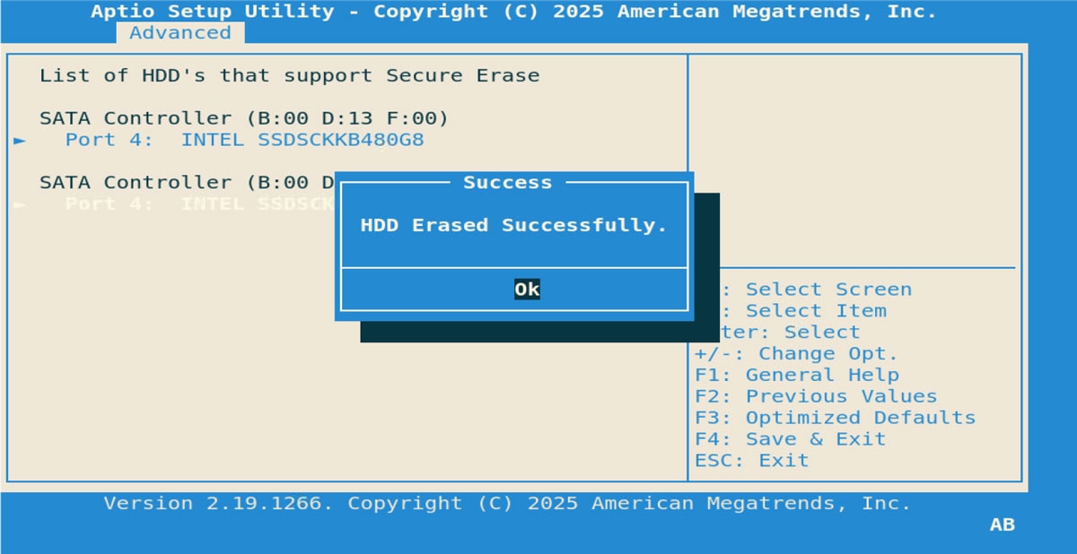
Ensure that the solid-state drive (SSD) in the replacement chassis is empty or factory-formatted.
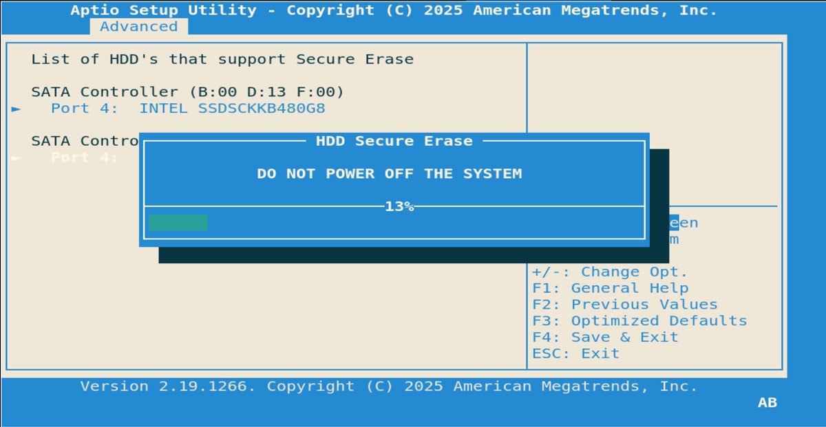
 Caution |
Do not power on the replacement chassis with any route processor (RP) installed prior to the chassis replacement. |
Follow these steps to replace a Cisco NCS 1010 chassis.
Procedure
|
Step 1 |
Collect and save the pre-check system information. Run these commands and save the command output for post-check comparison: Example: |
|
Step 2 |
Back up the running configuration. Copy the backup file to an external location after you verify that the backup file exists. Example: |
|
Step 3 |
Prepare the hardware records.
|
|
Step 4 |
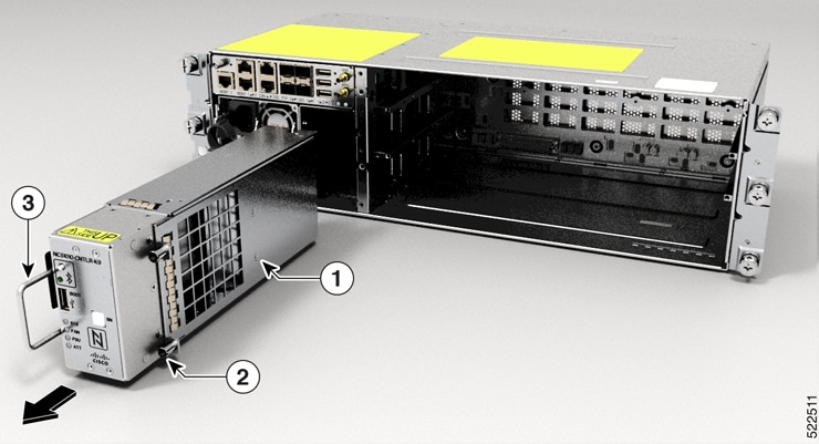
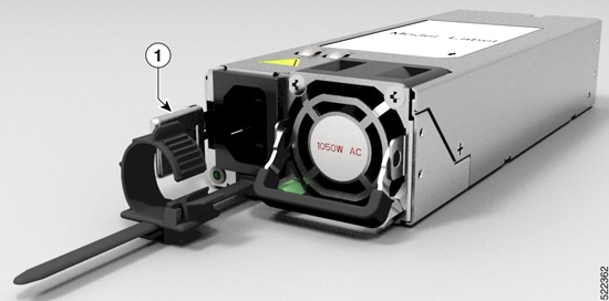
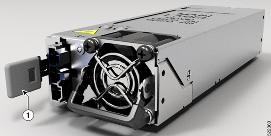
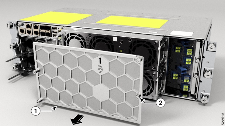
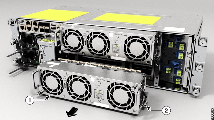
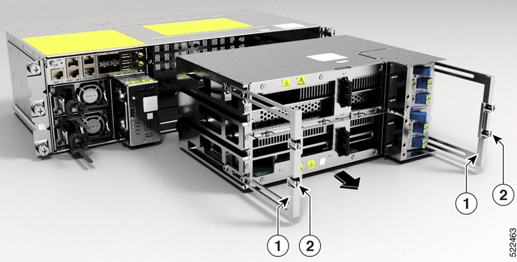
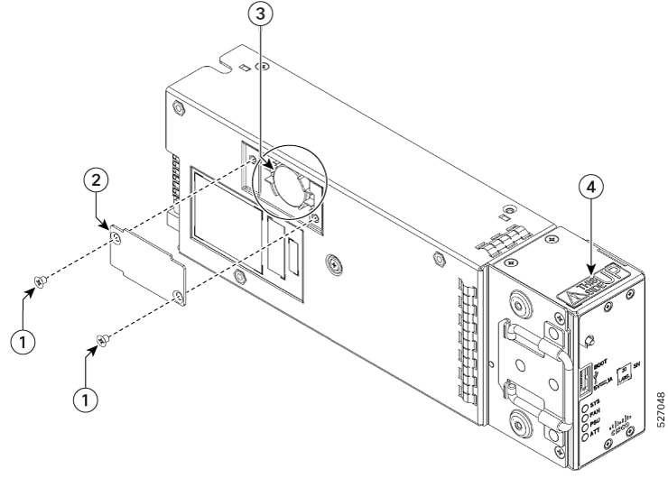
Power down the existing chassis and remove the hardware.
|
|
Step 5 |
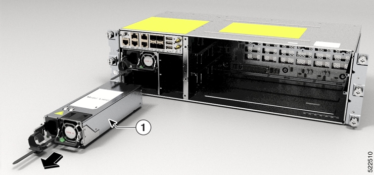
Install the replacement chassis and modules.
|
|
Step 6 |
Reconnect the cabling and start the replacement chassis.
|
|
Step 7 |
Verify the post-check system state. Run these commands and compare the command output with the pre-check output: Example: |
|
Step 8 |
Complete the final validation.
|
The replacement chassis runs with the intended software and configuration, restored cabling, recovered traffic and services, and no unexpected alarms.
What to do next
If the system starts with the wrong software version or configuration, take these steps to recover:
-
Treat this condition as a Disaster Recovery boot caused by a chassis SSD that is not empty,
-
Reinstall the intended software release and fixes.
-
Restore the saved configuration backup.
-
Reboot and revalidate the node.
If issues are observed, collect these logs:
-
show tech ncs1010 detail
-
show hw-module fpd
-
show platform
-
show alarms brief system active
-
show install active
-
show install fixes active
 Feedback