Band Failure Recovery

This chapter describes the band failure recovery optical application for Cisco NCS 1010.

Table 1. Feature History

Feature Name

Release Information

Description

Band Failure Recovery (BFR) Pause

Cisco IOS XR Release 7.10.1

Use the new  bfr-pause configuration command from this release to pause the BFR function. Unlike in the previous releases, the BFR pause state is now preserved during a system reload. BFR pause stays paused indefinitely until you resume it.

Command added: bfr-pause

olc bfr-pause (Command

deprecated)

Cisco IOS XR Release 7.10.1

The command olc bfr-pause is deprecated starting R7.10.1. To pause and resume BFR, use the bfr-pause command.

To upgrade from R7.9.1 to R7.10.1 or later with BFR pause enabled, before upgrading software, pause BFR on the OLT-C band using the olc bfr pause command before beginning the software upgrade. Once the upgrade is finished, pause and resume BFR using the bfr-pause configuration command on the OLT-C and OLT-L bands.

Band Failure Recovery (BFR)

Cisco IOS XR Release 7.9.1

During the C+L band network bring up, as both the bands travel through the same fiber, optical power is transferred from higher frequency to lower frequency due to SRS (Stimulated Raman Scattering). This degrades the C-band channel power and causes the existing C-band power profile to change.

BFR compensates for this dynamic power change by adjusting the power profile that minimizes the impact when upgrading from C-band to the C+L band network. BFR also adjusts power during a band failure to minimize the impact on the surviving band.

Band Failure Recovery

A band failure recovery is a mechanism that

  • applies dual-band PSD profiles to both C-band and L-band devices to compensate for power transfer caused by Stimulated Raman Scattering (SRS),

  • coordinates with agent nodes along the transmission path, and

  • manages PSD profile switching and recovery of each node in case of band failure.

Band Failure Recovery in C-band and L-band optical networks

NCS 1010 can be configured to operate in both C-band and L-band wavelengths to increase the capacity of optical fibers. This is achieved by connecting the C-band OLT or ILA line cards to the corresponding L-band OLT or ILA line cards. When C-band and L-band signals travel through the same fiber, SRS causes a transfer of optical power from higher to lower frequencies. This process alters the C-band power profile . BFR compensates for this by applying dual-band PSD profiles to both C-band and L-band devices.

The source OLT node functions as the BFR manager for all nodes in the transmit direction. Other nodes in the path act as BFR agent nodes and report to the manager. The manager node collects information from agent nodes, coordinates failure, and recovery actions.

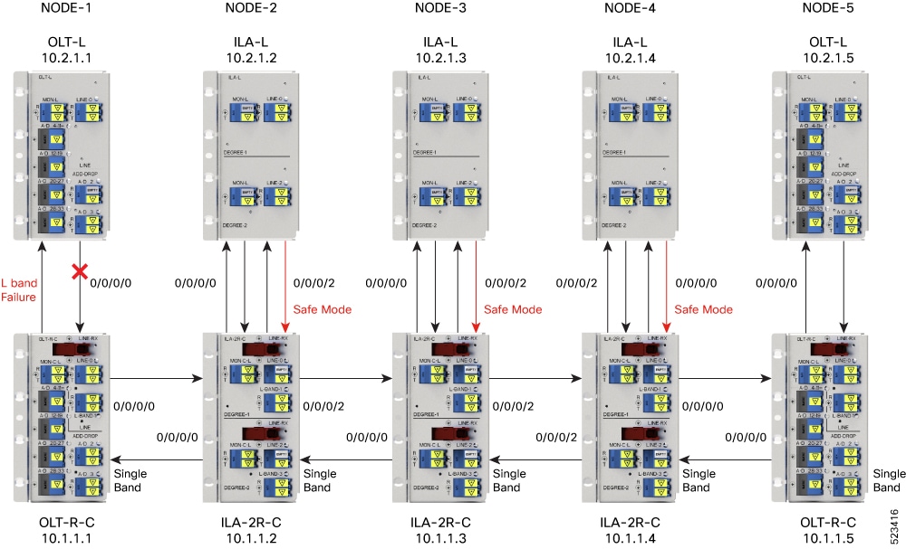
  1. When a band fails in a C and L band network, the surviving band experiences a change in optical power due to the absence of SRS.

  2. The BFR manager sends commands to the agent nodes to switch the PSD profile on the surviving band to a single-band PSD profile.

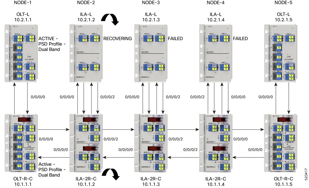
  3. After resolving the failure, the BFR manager initiates recovery on each failed band node to ensure there is no traffic impact on the surviving band.

Enable BFR on the controller

BFR is not enabled by default. It is enabled automatically if partner band IP address and dual-band PSD configurations are present on both the C-band and L-band cards.

Before you begin

Disable link tuner and gain estimator before BFR is automatically enabled.

Procedure


Step 1

Enter the partner-band-port command to configure the partner band IP address.

Example:


partner-band-port ipv4 address ip-address controller Ots0/0/0/x


Step 2

Enter the dual-band-port command to configure the dual-band PSD profile.

Example:


dual-band-psd index value


For more information about these configurations, see partner-band-port and Configure APC .


BFR is enabled on the system and is operational.

View BFR status on all nodes

Procedure


Use the show olc band-status command to view the status of BFR on all the nodes.

This example shows the status of BFR on all the nodes of a controller. BFR shows a Running status. BFR applies dual band PSD to both bands.

Example:


RP/0/RP0/CPU0#show olc band-status 
Tue Dec 13 10:45:30.594 UTC
Controller              : Ots0/0/0/0
Self-Band               : C-Band
BFR status              : Running
Node RID                : 10.1.1.1
Self IP Address     : 192.0.2.1
Self Controller         : Ots0/0/0/0
Partner IP address      : 192.0.2.2
Partner Controller      : Ots0/0/0/0
Partner link status     : UP
C-Band status           : ACTIVE
C-Band PSD              : Dual Band
L-Band status           : ACTIVE
L-Band PSD              : Dual Band
Node RID                : 10.1.1.2

Self IP Address         : 192.0.2.21
Self Controller         : Ots0/0/0/0
Partner IP address      : 192.0.2.22
Partner Controller      : Ots0/0/0/2
Partner link status     : UP
C-Band status           : ACTIVE
C-Band PSD              : Dual Band
L-Band status           : ACTIVE
L-Band PSD              : Dual Band
Node RID                : 10.1.1.3
Self IP Address     : 192.0.2.31
Self Controller         : Ots0/0/0/0
Partner IP address      : 192.0.2.32
Partner Controller      : Ots0/0/0/2
Partner link status     : UP
C-Band status           : ACTIVE
C-Band PSD              : Dual Band
L-Band status           : ACTIVE
L-Band PSD              : Dual Band
Node RID                : 10.1.1.4
Self IP Address     : 192.0.2.41
Self Controller         : Ots0/0/0/0
Partner IP address      : 192.0.2.42
Partner Controller      : Ots0/0/0/0
Partner link status     : UP
C-Band status           : ACTIVE
C-Band PSD              : Dual Band
L-Band status           : ACTIVE
L-Band PSD              : Dual Band
Node RID                : 10.1.1.5
Self IP Address     : 192.0.2.51
Self Controller         : Ots0/0/0/0
Partner IP address      : 192.0.2.52
Partner Controller      : Ots0/0/0/0
Partner link status     : UP
C-Band status           : ACTIVE
C-Band PSD              : Dual Band
L-Band status           : ACTIVE
L-Band PSD              : Dual Band
                    

For more information about this command, see the show olc band-status command in the Command Reference for Cisco NCS 1010 guide.

Note


If the OLC process is restarted on OLT-CR while Raman tuning is in progress, the Partner link status might show as DOWN in the output of the show olc band-status command. The Partner link status will change to UP after Raman tuning is completed.


Pause and resume BFR on the controller

While recovering from a span failure, if one of the bands is in a failed state, BFR is not initiated, and the other band is not recovered. In these cases, you can pause BFR, initialize it, and then resume BFR to start the process and recover the other band.

Procedure


Step 1

Enter the bfr-pause command to pause BFR on the controller.

Example:


RP/0/RP0/CPU0:#configure
RP/0/RP0/CPU0:(config)#optical-line-control
RP/0/RP0/CPU0:(config-olc)#controller ots 0/0/0/0
RP/0/RP0/CPU0:(config-olc-ots)#bfr-pause
RP/0/RP0/CPU0:(config-olc-ots)#commit
 

Step 2

Enter the no bfr-pause command to resume BFR on the controller.

Example:


RP/0/RP0/CPU0:#configure
RP/0/RP0/CPU0:(config)#optical-line-control
RP/0/RP0/CPU0:(config-olc)#controller ots 0/0/0/0
RP/0/RP0/CPU0:(config-olc-ots)#no bfr-pause
RP/0/RP0/CPU0:(config-olc-ots)#commit
 

For more information about these commands, see bfr-pause in the Command Reference for Cisco NCS 1010.

Note


To upgrade from R7.9.1 to R7.10.1 or later with BFR pause enabled, before upgrading software, pause BFR on the OLT-C band using the olc bfr pause command before beginning the software upgrade. Once the upgrade is finished, pause and resume BFR using the bfr-pause configuration command on the OLT-C and OLT-L bands.


BFR is paused and resumed, which can help recover bands after a span failure.

Events leading to band failure

Band failure can occur due to several events, such as connectivity issues, device failures, and power loss.

Events leading to band failure

Band failure can happen due to any of these events:

  • Optical connectivity fails between devices operating in the C-band and L-band.

  • The amplifier or controller on the L-band or C-band device has failed.

  • The amplifier on the L-band or C-band is shut down due to Optical Safety Remote Interlock (OSRI).

  • The node is shut down due to power failure.

  • Line cards operating in the L-band or C-band are in a cold-reload state.

  • A card operating in the L-band or C-band fails.

  • Multiple fiber cuts and high availability events.

  • High back reflection.


Note


Span fiber failure is not considered as band failure as both bands are impacted due to the failure.


Example of L-band failure

This scenario illustrates the BFR procedure in the event of an L-band failure. As soon as the band failure is detected, BFR sets safe mode on the failed band devices and switches the PSD profile of the surviving band devices to single-band PSD. The status of the devices operating in the C band is ACTIVE and the PSD profile for the devices is displayed as Single Band.

Figure 1. Example of L-band failure
Example of L-band failure

This example shows the status of BFR when the L-band is in the FAILED state. In this case, all the C-band nodes are switched to single-band PSD profiles and L-band devices are set to the safe mode.


RP/0/RP0/CPU0#show olc band-status
Controller              : Ots0/0/0/0
Self-Band               : C-Band
BFR status              : Running
Node RID                : 10.2.1.1

Self IP Address         : 192.0.2.1
Self Controller         : Ots0/0/0/0
Partner IP address      : 192.0.2.2
Partner Controller      : Ots0/0/0/0
Partner link status     : UP
C-Band status           : ACTIVE
C-Band PSD              : Single Band        
L-Band status           : FAILED
L-Band PSD              : NA
Node RID                : 10.2.1.2
 
Self IP Address         : 192.0.2.21
Self Controller         : Ots0/0/0/0
Partner IP address      : 192.0.2.22
Partner Controller      : Ots0/0/0/2
Partner link status     : UP
C-Band status           : ACTIVE
C-Band PSD              : Single Band
L-Band status           : FAILED
L-Band PSD              : NA
Node RID                : 10.2.1.3

Self IP Address         : 192.0.2.31
Self Controller         : Ots0/0/0/0
Partner IP address      : 192.0.2.32
Partner Controller      : Ots0/0/0/2
Partner link status     : UP
C-Band status           : ACTIVE
C-Band PSD              : Single Band
L-Band status           : FAILED
L-Band PSD              : NA
Node RID                : 10.2.1.4
Self IP Address     : 192.0.2.41
Self Controller         : Ots0/0/0/0
Partner IP address      : 192.0.2.42
Partner Controller      : Ots0/0/0/0
Partner link status     : UP
C-Band status           : ACTIVE
C-Band PSD              : Single Band
L-Band status           : FAILED
L-Band PSD              : NA
Node RID                : 10.2.1.5
Self IP Address     : 192.0.2.51
Self Controller         : Ots0/0/0/0
Partner IP address      : 192.0.2.52
Partner Controller      : Ots0/0/0/0
Partner link status     : UP
C-Band status           : ACTIVE
L-Band status           : FAILED
L-Band PSD              : NA
            

Band failure recovery in various scenarios

After the optical fiber fault is cleared, BFR starts the recovery procedure on each failed band node individually. BFR also ensures that traffic is not impacted.

Band failure recovery

After the optical fiber fault is cleared, BFR starts the recovery procedure on the failed band nodes one at a time. BFR also ensures that traffic is not impacted. The PSD profiles on the recovered and surviving bands are switched to dual-band PSD profiles.


Note


  • Recovery procedure is initiated only if all the nodes (both C-band and L-band) are active and reachable.

  • BFR runs the recovery procedure on the failed band while APC shifts the PSD profiles. APC must be enabled on both C and L-band devices for BFR to work. We recommend pausing BFR before running the apc-pause or apc disable commands.


This figure shows how BFR recovers from an L-band failure. After the fiber fault is cleared, BFR starts recovery on all C and L-band nodes one node at a time. The recovery procedure on Node 1 is completed and the status is shown as ACTIVE. The recovery procedure on Node 2 is in progress, so the node status is shown as RECOVERING. BFR starts recovery on each remaining node, one at a time, after recovering Node 2.

Figure 2. Example of BFR recovering nodes
Example of BFR recovering nodes

This example shows the C and L-band status as RECOVERING on the 192.0.2.1 node:


RP/0/RP0/CPU0:#show olc band-status
Controller              : Ots0/0/0/0
Self-Band               : C-Band
BFR status              : Running
Node RID                : 10.1.1.1
Self IP Address     : 192.0.2.1
Self Controller         : Ots0/0/0/0
Partner IP address      : 192.0.2.2
Partner Controller      : Ots0/0/0/0
Partner link status     : UP
C-Band status           : ACTIVE
C-Band PSD              : Dual Band
L-Band status           : ACTIVE
L-Band PSD              : Dual Band
Node RID                : 10.1.1.2
Self IP Address     : 192.0.2.21
Self Controller         : Ots0/0/0/0
Partner IP address      : 192.0.2.22
Partner Controller      : Ots0/0/0/2
Partner link status     : UP

C-Band status           : RECOVERING
                 
C-Band PSD              : NA

L-Band status           : RECOVERING
 
L-Band PSD              : NA
Node RID                : 10.1.1.3

Self IP Address         : 192.0.2.31
Self Controller         : Ots0/0/0/0
Partner IP address      : 192.0.2.32
Partner Controller      : Ots0/0/0/2
Partner link status     : UP
C-Band status           : ACTIVE
C-Band PSD              : Single Band
L-Band status           : FAILED
L-Band PSD              : NA
Node RID                : 10.1.1.4

Self IP Address         : 192.0.2.41
Self Controller         : Ots0/0/0/0
Partner IP address      : 192.0.2.42
Partner Controller      : Ots0/0/0/0
Partner link status     : UP
C-Band status           : ACTIVE
C-Band PSD              : Single Band
L-Band status           : FAILED
L-Band PSD              : NA
Node RID                : 10.1.1.5

Self IP Address         : 192.0.2.51
Self Controller         : Ots0/0/0/0
Partner IP address      : 192.0.2.52
Partner Controller      : Ots0/0/0/0
Partner link status     : UP
C-Band status           : ACTIVE
L-Band status           : FAILED
            

Single band failure recovery on non-Raman network

After the optical fiber fault is cleared, BFR performs these operations for single band failure on a non-Raman network.

  • Starts recovery on the failed band one node at a time.

  • After the recovery is completed and both bands are active, BFR switches the PSD profiles on both bands to dual-band PSD.

Span failure recovery

On a C and L band network, when both bands fail, BFR does not change the PSD profile to single-band PSD. After the failure is cleared, both bands recover quickly.

When a span failure is cleared on a Raman network and Raman tuning is disabled, BFR starts recovery of nodes. If Raman tuning is enabled, BFR suspends recovery and resumes it only after Raman tuning is completed.

Single band failure recovery on a Raman network

On a C+L band network without Raman amplifiers, when a band fails, Loss of Signal (LOS) is reported because the total power drops below the safe value. This shuts down the amplifiers on other nodes. If a band fails on the near end node of a Raman network, the far end amplifiers receive some band power because of ASE. In this case, LOS is not reported and the amplifiers on far end nodes remain active. BFR ensures that recovery on the far end nodes is started even if the amplifiers on the nodes are active because of ASE and sets safe mode on the failed band.

Once the optical fiber fault is cleared on a Raman network, if Raman tuning is started, BFR suspends recovery and resumes it only after Raman tuning is completed. If Raman tuning is not started, BFR starts the recovery of nodes one by one.

Band failure recovery due to device in headless mode

In the event of a band failure on a network with an OLT device in headless mode, BFR performs these operations.

  • BFR does not switch the PSD profile to single-band PSD.

  • BFR does not run the recovery procedure.

In the event of a band failure on a network with an ILA device in headless mode, BFR performs these operations.

  • BFR switches the PSD profile to single-band PSD on all the nodes that are reachable by C-band OLT.

  • BFR does not run the recovery procedure on all the OLT and ILA nodes.

  • If one or more nodes on the network are in headless mode, BFR is not initiated, which might affect traffic recovery. Perform these tasks to restore traffic:

    1. Pause BFR

    2. Initialize BFR

    3. Resume BFR

For more information about these commands, see the Command Reference for Cisco NCS 1010 Guide.