Remove and Replace Cisco NCS 1004 Modules

This chapter describes the procedures to replace Cisco NCS 1004 modules.


Caution


All the modular slots in the NCS 1004 chassis should always be populated with respective modules (line-cards, controller, PSU & fan units). Empty line card slots to be populated with filler modules, which are shipped with the chassis. The replacement or upgrade of the modules (Online Insertion or Removal, OIR) to be performed only when the ambient temperature is below 30-degree C. The OIR of modules should be completed within five minutes to prevent overheating of the components.


Online Insertion and Removal of a Line Card

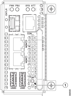
The Cisco NCS1004 controller unit provides a push button to initiate Online Insertion and Removal (OIR) during the upgrade or replacement of line cards. The same process is to be followed when a filler module is replaced with a line card. This button is used to prepare the system for the imminent loss of thermal efficiency due to the air leakage from the open slot (when the line card or filler card is removed from the chassis). The OIR button sets all fan units to maximum speed for 90 seconds which brings down the temperature of all internal components. After 90 seconds, the user can safely remove the line card or filler module from the chassis.
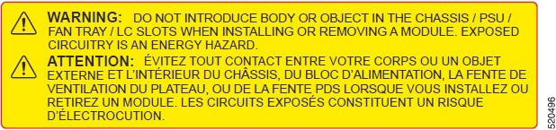

Caution


The OIR of procedure for line card or filler module to be performed only when the ambient temperature is below 30-degree C and should be completed within five minutes to prevent overheating of the chassis components.


Procedure


Step 1

Press the OIR button; refer the following image.

The ATT LED on the controller unit starts blinking and the fan units are set to the maximum speed.

Caution


Wait for 90 seconds before proceeding.

Figure 1. Replacing a Line Card - OIR Button on the Controller

1

OIR Button

Step 2

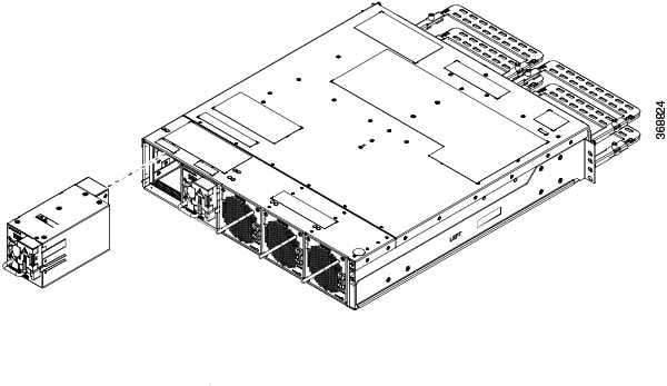
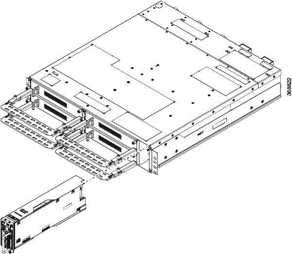
After the blinking stops, remove the line card from the chassis and replace it with another line card. For the detailed line card installation procedure, see Line Card Installation.

Fan units continue to run at maximum speed, until the new line card module is inserted back. After the new line card is detected, the speed of the fan units return to their normal speed.

Note

 
If the filler card or line card is not removed from the chassis within 10 seconds after the ATT LED stops blinking, the fan units return to the normal speed.

Remove and Replace Power Supply Unit

This task has information about removing and replacing the power supply units.

Before you begin

Remove the connections to the power supply:

  • Disconnect power from the breaker before disconnecting power from the power supply unit.

  • Remove the cable retainers and the power cables, in case of an AC power supply unit.

  • Remove the protection covers, fasteners and lugs, in case of a DC power supply.

Procedure


Step 1

Press the locking latch towards the left to release the lock.

Figure 2. Locking Latch on the DC PSU

1

Locking latch

Figure 3. Locking Latch on the AC PSU

1

Locking latch

Step 2

Using the handle with one hand and supporting the PSU with the other, gently pull out the PSU from the slot.

Figure 4. Removing the Power Supply Unit

For replacing the PSU, see Power Supply.


Remove and Replace Controller

This procedure has details about removing and replacing the controller.

Procedure


Step 1

Using a Torx screwdriver, unfasten the two screws on the controller.

Step 2

Using the handle with one hand, and supporting the controller with the other, gently remove the controller from the slot.

Figure 5. Removing the Controller

What to do next

For replacing the controller, see Install Controller.

Remove and replace the battery in the controller

Use this task to remove and replace the controller battery.

Before you begin

Ensure you have these tools and equipment

  • #1 Phillips-head, Hex 5.5 torque screwdriver

  • Plastic spudger/pry tool

  • Plastic or ceramic tweezers

  • Electrostatic discharge (ESD) strap or other grounding equipment such as a grounded mat

  • Replacement Battery – Choose any one from the options:

    • CR-2032L/BN — Panasonic

    • 06032 101 501 — Varta Microbattery Inc.

    • 100272 — Renata


Caution


Handle them only by carrier edges and use an electrostatic discharge (ESD) wrist-strap or other grounding device to avoid damage.


Warning


Ensure the system is shut down and power is removed before proceeding.

There is danger of explosion if the battery is replaced incorrectly. Replace the battery only with the same or equivalent type recommended by the manufacturer. Dispose of used batteries according to the manufacturer’s instructions.


Procedure


Step 1

Remove the PCB assembly from the controller.

  1. Remove the face plate by unscrewing the seven M3x0.5x3 mm screws with the #1 Phillips-head screwdriver.

    Figure 6. Dettaching the controller faceplate
    The controller faceplate is being detached.

    1

    Bottom M3x0.5x3 mm screws

    2

    Left side M3x0.5x3 mm screws

    3

    Top M3x0.5x3 mm screws

    4

    Controller handle

  2. Remove the two M2.5x0.45x8 mm screws on the side with the #1 Phillips-head screwdriver.

    Figure 7. Dettaching the side screws
    Removing the two M2.5x0.45x8 mm screws on the side.

    1

    Two M2.5x0.45x8 mm screws
  3. Turn the controller and remove the protection cover by unscrewing.

    1. three M3x0.5x3.70 mm Hex nuts using Hex 5.5 driver

    2. two M3x0.5x7 mm screws using #1 Phillips-head screwdriver

    Figure 8. Removing the side panel
    Removing the side panel.

    1

    Two M3x0.5x7 mm screws

    2

    Three M3x0.5x3.70 mm Hex nuts

    3

    Protection cover

    Note


    Keep the removed screws and nuts organized for reassembly.

  4. Remove the PCB assembly carefully, avoiding damage to the Interposer connector.

    Figure 9. Removing the PCB assembly
    Removing the PCB assembly

    1

    Interposer connector

    2

    PCB assembly

Step 2

Remove the RTC battery.

  1. Locate the vertical RTC battery socket on the PCB assembly.

    Figure 10. Locating the vertical RTC battery socket
    Locate the vertical RTC battery socket on the PCB assembly.

    1

    Vertical RTC battery socket

  2. Remove the battery from the socket using the plastic spudger tool to push against the spring and release the battery.

Step 3

Install the new RTC battery.

  1. Identify the battery polarity.

    The positive side of the battery has the "CR2032" text and a plus sign (+) on it, and the negative side is flat.

  2. Insert the battery at a slight angle around 30-degrees to the holder's opening, with the negative flat side facing the internal lower spring contact.

  3. Gently push the battery inward toward the spring, then press down until it clicks securely into place under the retaining tabs.

  4. Ensure the battery is seated snugly and correctly. The positive side of the battery should be facing the retainer clip/tab when installed in the vertical holder.

Step 4

Reassemble the controller unit.

  1. Mount the PCB assembly back onto the carrier, ensuring the Interposer connector locks in place.

  2. Attach the protection cover by tightening the Hex nuts and screws to a torque of 5.5 ± 0.5 in.lb where specified.

  3. Turn the controller and tighten the two M2.5x0.45x8 mm screws using the #1 Phillips-head screwdriver to a torque of 3.3 ± 0.3 in.lb.

  4. Reattach the face plate by tightening the seven M3x0.5x3 mm screws using #1 Phillips-head screwdriver to a torque of 3.3 ± 0.3 in.lb.

    Note


    Fasten the side screws of the face plate first, followed by the bottom screws, to align the connector location.


The new RTC battery is correctly installed and seated. The controller is ready for reassembly and power-up.

What to do next

  • Power on the controller and verify that it recognizes the new RTC battery and no battery errors are reported.

  • Safely dispose the old battery according to local practices.

Remove and Replace Fan Unit

This task has information about removing and replacing the fan unit.


Caution


OIR duration for the fan tray unit at 30-degree C ambient temperature, is five minutes.


Procedure


Step 1

Push and hold the spring-loaded lever towards the left with your thumb (unlock position).

Figure 11. Spring-loaded Lever in Holding or Unlock Position

1

Sping-loaded lever

Step 2

Use the handle on the fan unit to pull the fan unit out of the chassis, while supporting it with the other hand.

Figure 12. Removing the Fan Unit

What to do next

For replacing the fan unit, see Install Fan Unit.

Wipe Data in Disk Using Secure Erase

When NCS 1004 becomes faulty, contact TAC to open a Return Material Authorization (RMA) request. Before opening a RMA request, the user can securely erase data in NCS 1004 disks using the Secure Erase feature.


Warning


Use this procedure only during RMA.


Before you begin

The NCS 1004 unit that is planned for RMA must be taken out of the data center and the network. The user must access NCS 1004 only using the console port.

Procedure


Step 1

When NCS 1004 boots (power cycle), the following message appears.


Version 2.19.1266. Copyright (C) 2019 American Megatrends, Inc.                 
BIOS Date: 07/09/2019 14:44:28 Ver: 0ACHI420                                    
Press <DEL> or <ESC> to enter setup.
Press DEL or ESC key to enter BIOS.

Press DEL or ESC key to enter BIOS.

Step 2

Select the Advanced tab using the arrow keys.

The disk security details such as HDD Secure Erase are displayed in the Advanced tab.

Step 3

Select HDD Secure Erase to securely erase data.

The list of SSDs that support Secure Erase is displayed. D:13 is CPU SSD and D:14 is Chassis SSD.

Step 4

Select the SSD from which you want to erase data using the arrow keys.

Step 5

Select Yes in the Confirmation screens.

The system proceeds to securely erase data in the selected SDD after these confirmations.