Introduction to Next Generation Wireless Site Maps
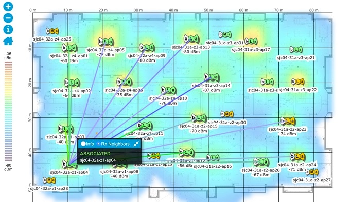
Cisco Prime Infrastructure introduces Next Generation wireless site maps from Release 3.2. The Next Generation site maps are enhanced with a new user interface which offers larger and more detailed maps.
To access the Next Generation wireless site maps, choose .
The Domain Sidebar menu lists the campuses, buildings, outdoor areas, and floors in a tree view. When you click a campus, building, outdoor area, or floor in the tree view, the corresponding map along with different panels appear in the right pane.
How Wireless Site Maps Are Organized
The wireless site maps have a predetermined hierarchy:
-
Campuses are the highest level in the map hierarchy. Campus represents a single business location or site. Campuses consist of at least one building, with one or more floor areas, and many outside areas.
-
Buildings represent single structures within a campus, serving to organization-related floor-area maps. You can add as many buildings you want to a single campus map. A building can have one or more floors and outside areas associated with it. You can add buildings only to a campus map.
-
Floor areas are within the building which comprises of cubicles, walled offices, wiring closets, and so on. You can add floor areas only to building maps. You can add up to 100-floors to each building map that you create.
-
Basement levels are similar to floor areas, except they are numbered in reverse order from floor areas. You can add basements to building maps only. You can add up to 100 basement levels to each building map you create, in addition to the 100 floor areas.
-
Outside areas are the exterior locations. Although they are typically associated with buildings, outside areas must be added directly to campus maps, at the same level as buildings. You can add as many outside areas to a campus map as you want.
Cisco Prime Infrastructure comes with two default campus maps:
-
System Campus—This is the default campus map. If you create a new building, floor, basement, or outside area, but do not create as part of your campus map, these subordinate maps are automatically created as children of the System Campus map.
-
Unassigned—This is the default map for all network endpoints and hosts that you have not assigned to any other map (including the System Campus).
Guidelines for Preparing Image Files for Use Within Wireless Site Maps
-
Use any graphics application that saves to the raster image file formats such as: PNG, JPEG, or GIF.
-
For floor and outdoor area maps, Cisco Prime Infrastructure allows bitmap images such as PNG, JPEG, GIF, and CAD vector formats (DXF and DWG).
-
Ensure that the dimension of the image is larger than the combined dimension of all buildings and outside areas that you plan to add to the campus map.
-
Maximum dimensions supported for images used in wireless floor plan maps are:
-
PNG images - 20,000 pixels by 15,000 pixels.
-
JPG images - 20,000 pixels by 20,000 pixels.
-
-
Gather the horizontal and vertical dimensions of the site in feet or meters before importing. This helps you to specify these dimensions during import.
-
If you are entering campus, building, floor, or outside area dimension in meters, change the default map measurement units to meters.
-
Once you have created the maps, you can assign network elements to them. You can manually do this by selecting individual devices and assigning them to campuses, buildings, floors, and outside areas as needed. For wireless access points and access controllers, you can add them to your maps automatically by using your organization’s access points or wireless access controllers naming hierarchy.
Troubleshoot Problems with CAD Image File Imports in Wireless Site Maps
Cisco Prime Infrastructure uses a native image conversion library to convert CAD and MET vector files into raster format. Select one of the following supported target raster formats during the CAD or MET file import: PNG, JPEG or (JPG), and GIF.
If Cisco Prime Infrastructure cannot load the native image conversion library, it displays an error message saying "Unable
to convert the autocad file". If you receive this error message, make sure that all the required dependencies are met for
the native library using the Linux ldd command. The following four DLLs must be present under /webnms/rfdlls install directory in Cisco Prime Infrastructure: LIBGFL254.DLL, MFC71.DLL, MSVCR71.DLL, and MSVCP71.DLL. If dependency problem persists, install all the required libraries and then restart Cisco Prime Infrastructure server.
Floor and outside area map images imported from CAD files are enhanced for zooming and panning. Without zoom, the image clarity is close to that of the original CAD file. But an imported CAD file can appear blurred during zoom. If you are having a problem with blurred floor map images, make sure that all relevant parts of the image are clearly visible in the original CAD file. Then import the CAD file again, and choose PNG or GIF as the target conversion file format, instead of JPEG or JPG.
Large floor map images can take time to import. While the conversion is in progress, not all the image is visible on the map. If you have a high-resolution image (an image with a resolution of 180 megapixels and a file size of 60 MB), it may take two minutes or more for the imported image to appear on the map.


 Feedback